
Abstract
This paper details about weaving of single-layer 3D ‘T’ profile with fillet for use as insert in composite ‘T’ joints and ‘T’ stiffeners. The ‘T’ insert with fillet was woven using 3 K carbon tows on a narrow width multi-beam automatic loom. Weaving was carried out based on the double-cloth weaving principle. Novelty of the work lied in the approach adopted for designing of the weave architecture in developing 3D ‘T’ profile with fillet portion, arriving at the pick cycle diagram for weave design development which has been detailed in this paper. Test results of composite ‘T’ joints fabricated incorporating the insert showed strength improvement as well as change in crack propagation mode as compared to conventional ‘T’ joint. The continuous insert with fillet acted as a bridging member among the three sections of the ‘T’ joint, thus contributing to performance improvement.
Introduction
‘T’ Joint is a basic building block in composite aircraft structures which would be required when two structural members that are orthogonal to each other are required to be joined together. Here the transfer of load occurs in out-of-plane mode [1]. Examples of T-joint in an aircraft wing primary structure include the connection of skin–stringer, skin–rib and skin–spar joints [2]. It has been seen that these components, when made of composites, often fail near web–skin interface due to transverse normal and shearing stress components. Several attempts to develop and improve the performance of these joints are reported in literature. Soden and Hill [3] have developed a woven T skin with double web stiffener. Cartie et al. [4] have evaluated the carbon fibre/epoxy T-stiffener-to-skin joint reinforced through the thickness, by insertion of Z-fibre and tufting. With this effort, they have reported increase in pull-load and overall load-carrying ability. Stickler and Ramulu [5] have employed numerical methods to perform a detailed parametric study on composite ‘T’ joints with transverse stitching using the finite element method. Further they have evaluated the experimental and numerical analysis of transverse stitched T-joints using a fibre insertion process and PR 520 Toughened resin [6]. They are of the opinion that transverse stitching along the rib, at a location offset from the web, improved the pull-off strength of T-joints. Continuing their work [7] on tensile and shear loading studies of composite ‘T’ joints with transverse stitching, they are of the view that fiber insertions are effective beyond initial failure under flexure, but are not as effective beyond initial failure under tension and shear. Rao et al. [8] have carried out experimental investigations and non-linear finite element analysis of composite wing ‘T’ joints with transverse stitching in hygrothermal environments. They have concluded that, the transverse stitching at the web/skin interface zone adds to the transverse strength of the interface laminates and helps the T-joints to sustain higher loads and change the failure patterns. Zheng et al. [9] have used the concept of ‘flattening-weaving-unfurling’ approach to develop an integrated T-joint tube. Kumari and Sinha [1] have evaluated the effects of transverse stitching (using T300 fibres) and hygrothermal environment at the web-skin interface. They have used T300 fibres for transverse stitching. They are of the view that stitching affects only the local stresses and does not change the global stress distribution. They have concluded that optimum stitch density is 12–14 stitch/cm2. They have also seen that the transverse stitching at the web–skin interface zone adds to the transverse strengthening of the interface laminates and helps the T-joints to sustain higher loads in ambient conditions as well as under higher temperature and moisture concentration levels. Koh et al. [10] have studied the effect of Z pinning on stiffened joints made of carbon-epoxy composites. They have concluded that ‘Z’ pinning is an effective method to improve the properties of composite ‘T’ joints. Rispler et al. [11] have carried out experimental studies on tension pull-out tests of different types of inserts in the resin-rich area of the ‘T’ joint. They have concluded that addition of inserts improves the pull-out strength of thicker specimens. For thinner specimens, the use of inserts introduces geometric discontinuities by creating kinks on the fibres which cause stress concentration resulting in reduced pull-out strength. Otheguy et al. [12] have used PP layers to improve the bond quality of T joints. Yang et al. [13] have attempted self-healing of T joints by inserting a 3D mendable polymer network using fibre stitching technique using EMMA thermoplastic material as the healing agent. They have carried out tensile and DCB tests on the T joints. They have concluded that the novel concept of mendable thermoplastic stitching of carbon–epoxy T-joints have the multi-functional benefits of interlaminar toughening and self-repair. Nanayakkara et al. [14] have carried out experimental and analytical study of strengthening and toughening composite T joints by Z pinning. They have concluded that through-thickness reinforcement of the T-shaped sandwich composite joints with pins increased the peak fracture load and fracture energy. A spectrum of the literature surveyed above shows attempts to improve the ‘T’ joint strength has been mainly through transverse stitching, Z pinning, tufting, use of inserts in resin-rich area, 3D mendable polymer network etc. The present work uses yet another approach to improve the properties of the ‘T’ joint by using single-layer integrally woven 3D ‘T’ inserts. Single-layer inserts have previously been developed by various researchers such as Dale Abidaskov [15] who have patented the profile weaving of ‘H’, ‘Y’ and ‘Pi’ which are used as connectors in structural components, Walter [16] has woven a double ‘I’ beam using Nylon for applications in internal conduits and Chou and Chen [17] have developed single and multilayer cylindrical fabric. The novelty of this work lies in designing and weaving a single-layer 3D T insert incorporating the fillet region in the weave architecture by arriving at the pick cycle diagram for weave design development for use in composite ‘T’ joints. The design and weave details along with the pick cycle diagram required for weaving has been detailed in this paper. Composite preparation and evaluation has been elaborately discussed by Kundan et al. [18]. However, for the sake of completeness an outline on the composite development and its evaluation extracted from it is included here.
Weaving of the ‘T’ inserts
‘T’ profile with fillet was woven on a narrow width multi-beam automatic loom using 3 K carbon tows. The cross-section diagrams and dimensions of the profile are shown in Figure 1.
‘T’ insert with fillet [19] (all dimensions in mm; drawing not to scale).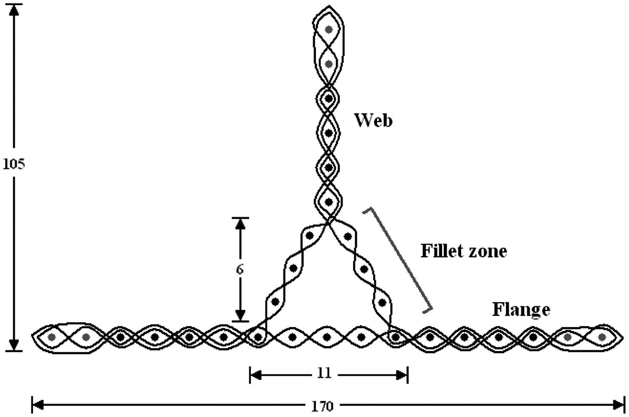
Weaving of T profile with fillet [19] was based on the double-cloth weaving principle in folded form as shown in Figure 2. It was then unfolded to form the ‘T’ profile, after taking out of the loom. The flexibility of the textile material to bend is utilized here.
Cross-section of folded form of T profile with fillet as woven on the loom.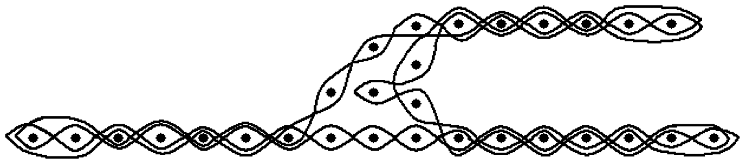
The following steps were adopted for weaving.
Generating the warp cross-section. Generating the pick cycle and pick repeat, ensuring weft continuity where required. Developing the cloth construction details including the weave design, drawing-in-order, lifting plan and denting order [20]. Determination of the number of warp threads based on profile dimensions, reed count and yarn count. Warp preparation [21] for let-off, leasing, drawing-in-through the heald shafts as per the drawing-in-order and denting through the reed as per the denting order. Weft winding onto the pirn of the shuttle. Weaving pick by pick as per the lifting plan. Take-up of the woven preform on the cloth roller.
Warp thread distribution for Let-off was from two separate beams as shown in Figure 3. This was required to ensure that the warp threads remain parallel (pre-requisite for weaving) in both the cloth sections (top and bottom) and also it helped in compensating for the tension variation during weaving of ‘T’ profile.
Warp distribution on to two beams. Vertical line depicts reed wire and hence specifies denting order.
During warp preparation, portion of the ‘T’ which was woven on the double-cloth principle had twice the number of thread in each dent when compared with the other portion, where the single cloth was formed. The fillet-forming portion of the profile had two, three and four warp threads in successive dents. The other portions of the ‘T’ profile had one thread in each dent forming single cloth (refer Figure 3). This denting non-uniformity was required to ensure uniform warp density throughout the profile architecture and also to have a stable, self-standing profile, especially at the intersection. In regular fabric weaving, increasing the density of the warp threads in the reed will change the cloth construction (especially ends per inch). However, in the case of profile weaving, increasing the density of the warp threads in the reed selectively will maintain uniform warp density throughout the profile architecture. Picking was carried out using the shuttle to provide continuous weft required to form the ‘T’ profile. Selvedge binding was by the continuous weft itself. The take-up was intermittent and was alternating on every two picks. The base weave chosen was plain to obtain a stable intersection. The profile was woven warp way so that continuous length of the ‘T’ could be obtained.
Pick cycle diagram for weave design development
Figure 4(a) shows the warp arrangement as on the loom (warp cross-section). This arrangement is decided by the folding direction of the profile and the density of the warp threads. Dots in each column correspond to number of warp threads in each dent. Weaving of the ‘T’ profile is accomplished by eight pick repeat cycle shown in successive figures from 4(b) to (i) depicting first to eighth pick, respectively. In all the descriptions below, the just inserted previous pick has been shown by means of dotted lines. L to R implies that the shuttle traveled from the left box to the right box and R to L implies that the shuttle traveled from the right box to the left box.
Picking cycle.
1st pick (L to R) – Figure 4(b): Here, the bottom layers of the warp threads were interlaced. All the warp threads of the second beam and alternate threads in the first beam are lifted up.
2nd pick (R to L) – Figure 4(c): The warp threads were interlaced selectively in the bottom right half of the warp threads. The left half of the warp threads were lowered down resulting in the weft floating over them.
3rd pick (L to R) – Figure 4(d): The warp threads were interlaced in the top layer continuing from the 2nd pick. The weft float of the 2nd pick was taken into the weave formation for the 3rd pick.
4th pick (R to L) – Figure 4(e): The warp threads in the top layer was interlaced and the shuttle traversed to left leaving a weft float without interlacing the warp threads in the bottom portion.
5th pick (L to R) – Figure 4(f): The warp threads were interlaced in the bottom right half continuing from the 4th pick. The weft float of the 4th pick was taken into the weave formation of the 5th pick.
6th pick (R to L) – Figure 4(g): The bottom layers of the warp threads were interlaced in this pick. All the warp threads of the second beam and alternate threads of the first beam (which were lowered down for the first pick) were lifted up.
7th pick (L to R) – Figure 4(h): Warp threads in the left half portion of the bottom layer and top layer were interlaced.
8th pick (R to L) – Figure 4(i): Shuttle traverses back interweaving the warp threads in top layer and bottom left half.
This completes one repeat of the ‘T’ profile 4(j) and the above eight pick cycle was continued sequentially and repetitively till the required length of the preform was obtained.
The weave design comprising the design, drawing-in-order and lifting plan are detailed in Figure 5.
Weave design: design; drafting-in; and lifting plan.
Figures 6 and 7 show the line diagram and the photograph of a narrow width multi-beam weaving machine for weaving single-layer 3D profiles and thick 3D preforms. The machine consists of six warp beams to feed multiple warp layers, 24 heald frames (electronically controlled), option to use rapier or shuttle for weft insertion, multi beat-up action for firm and compact beat-up, positive take-up for assured weft density and take-up at will for obtaining thick 3D performs. The working width of the loom was 400 mm.
Line diagram of the multi-beam weaving loom. Photograph of multi-beam weaving loom with single-layer 3D ‘T’ insert.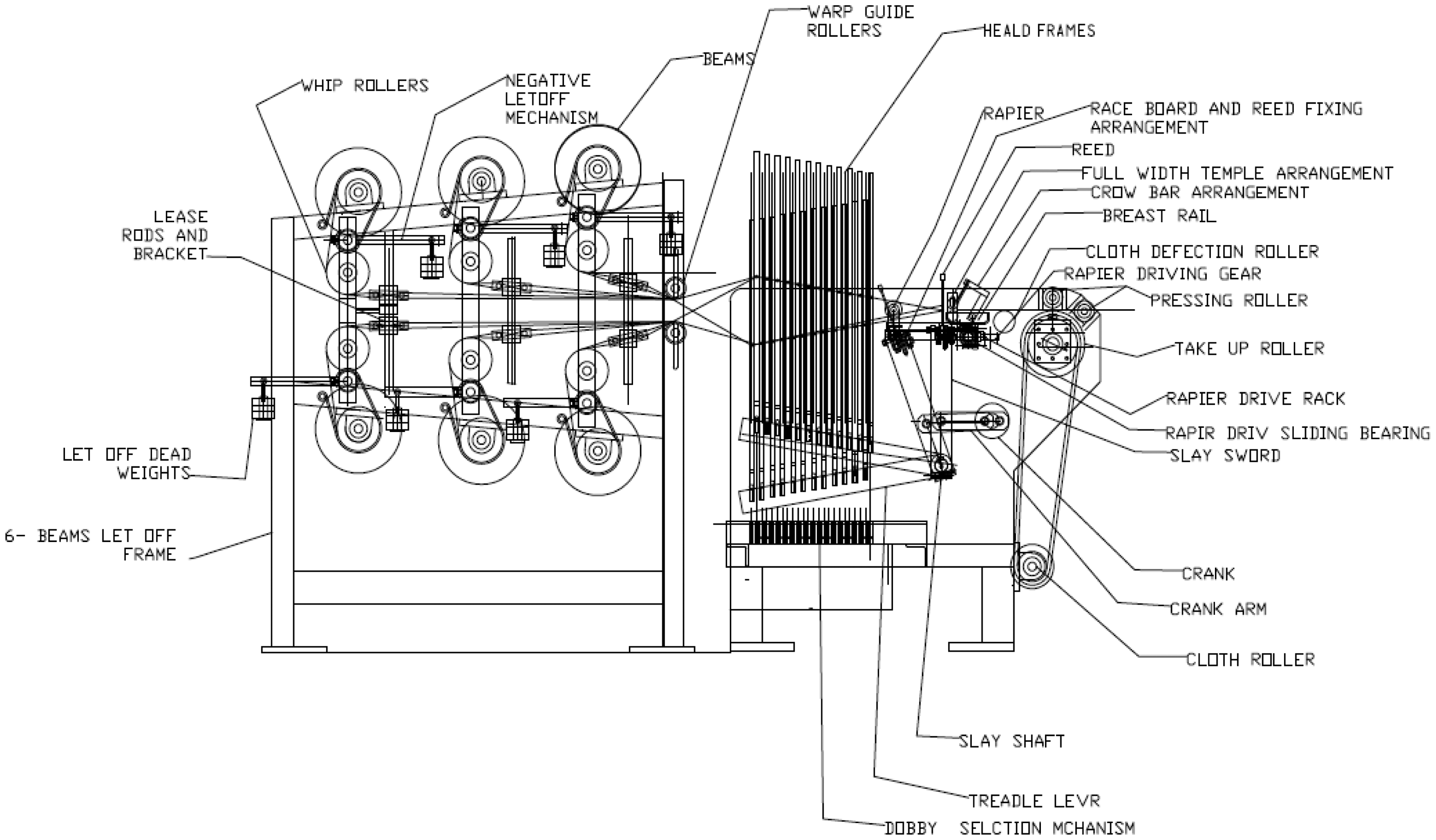

To explore the prospects of commercial viability these ‘T’ profiles with fillet were also successfully woven on a commercial Jacquard loom, thus ensuring the suitability of technology for production runs.
Specification of single-layer 3D ‘T’ profile with fillet.


Photograph of 3D woven ‘T’ profile.

Photographs of yarn in web, flange and fillet zone.
Composite test results
To understand the effect of the 3D woven ‘T’ profile with fillet (Series IV) in the composite performance [18], the woven profile was incorporated as insert in composite ‘T’ joint fabrication. T-joints were designed and developed using CSIR-NAL proprietary process called ‘Vacuum Enhanced Resin Infusion Technology (VERITy)’ [22] process using EPOLAM 2063 resin system. T-joints were subjected to the pull-off strength tests. For comparison purposes, a conventional ‘T’ Joint (without insert – Series I) was also fabricated and evaluated, which served as the reference configuration. In order to maintain the thickness of web and skin flange interface in Series I T-joints, two layers of 0 degree plies were added in the stiffener layup in the mid plane of basic T-joint as shown in Figure 10.
T-joint configuration [18].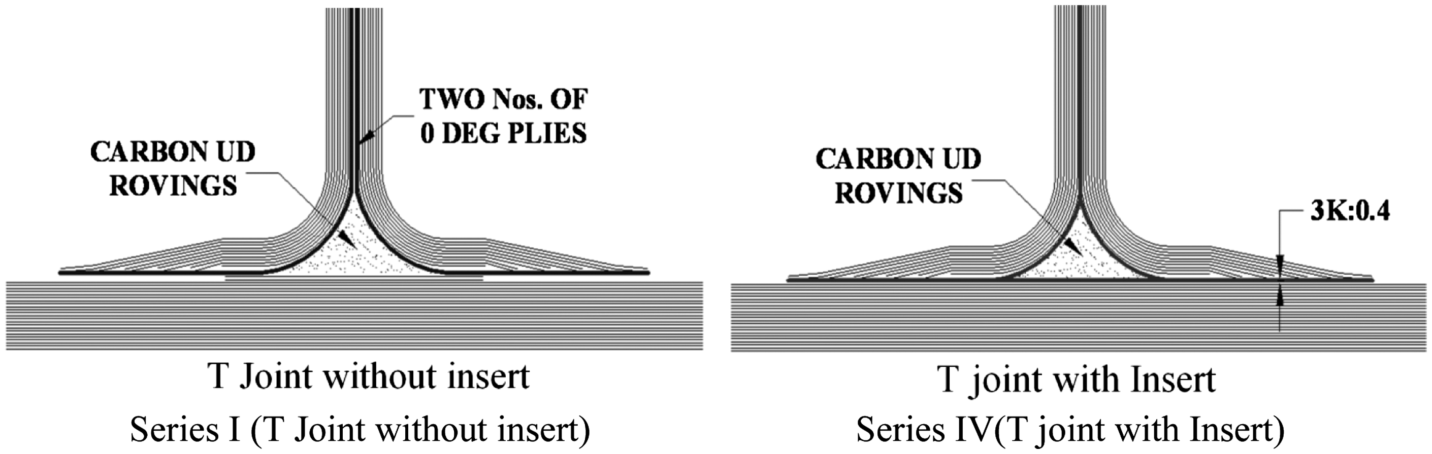
Figure 11 shows the pull-off test geometry and the loading direction. Holes were provided for bolting the specimen to the fixture mounted on a UTM (INSTRON) testing equipment. Tests were carried out at 1 mm/min crosshead speed and pull-off strength of T-joint was determined by loading the specimen to failure. Figure 12 shows the strength improvement plots of T joint without and with insert in terms of load per unit length of the joint (N/mm). The average failure load is the average value of three specimens each. Since the thickness varied at the fillet area for the two types of T joints, the normalised failure load in Figure 12 was calculated (using the formula detailed below) taking the weight of T joint without fillet as base
Test geometry of T pull specimens [18]. Strength improvement plot of ‘T’ joint without and with insert [18].


Figures 13 and 14 show the photographic record of the crack propagation at specific points of loading for ‘T’ joint without and with insert. The specimen edges were painted with white colour at the fillet region to capture the crack propagation details. Specimen fixture weight was 250 N and loading of specimens started thereof. Hence loading of specimens (y-axis) has been plotted from 250 N in Figures 13 and 14. The ultimate failure load was considered after deducting the specimen fixture weight of 250 N. T-joint consisting of woven 3D insert with fillet exhibited about 30% improved strength in pull-off mode when compared to the ‘T’ joint without fillet. A change in the crack propagation mode has also been observed.
Plots of crack propagation mode for ‘T’ joint without insert [18]. Plots of crack propagation mode for ‘T’ joint with insert [18].
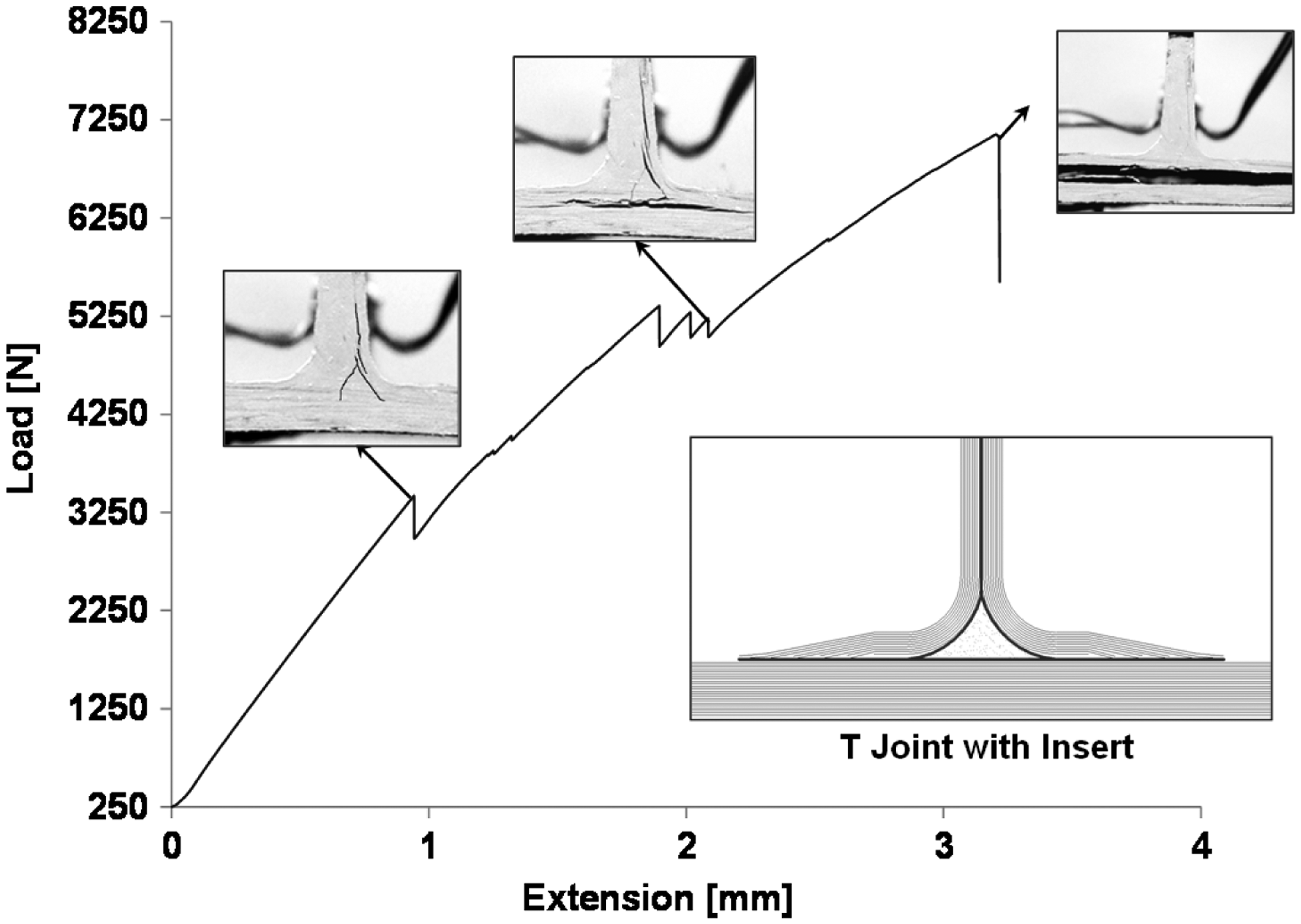
In the case of T joint without fillet, final failure occurred at the flange skin interface. In the case of T joint with fillet, crack started in the fillet region, propagation was prevented due to reinforcement continuity, and the final separation of the flange and skin occurred below the insert layer resulting in the final failure of the T joint. This can be attributed to the following aspect. The surface of the integral woven structure has ridges among the interlacements. These ridges act as locking zones for the matrix all along the three sections of the joint. The fillet portion also contributes to this aspect as it is specifically designed as per the contour requirements of the joint, thus contributing to performance improvement as compared to the ‘T’ joint without insert. During T pull tests, the insert with fillet helps in better load distribution as is evident in change in the crack propagation paths (Figure 14).
Conclusion
A novel weave design architecture with the necessary pick cycle diagram was evolved for the development of T insert with fillet. The single-layer 3D ‘T’ profile with fillet has been successfully woven on a narrow width multi-beam automatic loom. The ‘T’ profile was generated on an eight-pick weft repeat cycle. Composite ‘T’ joints fabricated using this single-layer 3D ‘T’ profile as insert showed improved pull strength. The ridges on the surface of the integral woven structure acted as locking zones for the matrix all along the three sections of the joint thus contributing to performance improvement as it has been specifically designed as per the contour requirements of the joint. Change in the crack propagation mode as compared with conventional T joints was also observed. Manufacturability has been established by weaving the same on a Jaquard loom to ensure the suitability of the technology for production runs. The fillet weaving is generic in nature and the same approach can be adopted for similar constructions such as I, J profiles for using them as inserts in composite fabrication. This technique looks promising for use in composite joints and stiffeners as it is practically and economically feasible for implementation.
Footnotes
Acknowledgements
The authors thank Director CSIR-NAL, Head CSMST and Head ACD for their encouragement and support. The authors thank Dr Sham Sundar for his initiation, Mr Arun of M/s Arun Fabrics for weaving on the Jacquard loom, M/s Kale Texnique for fabricating multi-beam automatic loom, Mr Ramaswamy and Mr Kamalakannan for their support in machine erection and maintenance and ACD for the development of composites and its evaluation. One of the authors, Mr Sandeep, is indebted to CSIR-NAL for providing the fellowship.
Declaration of Conflicting Interests
The author(s) declared no potential conflicts of interest with respect to the research, authorship, and/or publication of this article.
Funding
The author(s) received no financial support for the research, authorship, and/or publication of this article.