
Abstract
This article presents an experimental study of fusion-bonded polypropylene (PP) glass composite joints in the context of small craft manufacture. The objective is to investigate the manufacturing of lap joints and T-joints as a structural part of a small boat and study their properties, because a joining technique is a fundamental requirement of any boat construction technology. Results show that PP interlayers improve bond quality for both lap joints and T-joints and that woven precursor materials are preferred for T-joint manufacturing. It was also found that this technique produces higher lap shear strength values than adhesives and resistance welding, and that pull-out strength values were comparable with those of thermosetting designs, demonstrating that fusion bonding is a suitable joining technique for thermoplastic composite craft.
Keywords
Introduction
Thermoset-based composite materials have evolved during the last 70 years to become dominant in the industry. Both military and leisure boatbuilding have benefited from their ease of construction, cosmetic appearance, low weight and mechanical properties. 1 The boatbuilding field, however, has recently entered a further period of rapid change driven by the need for cleaner, more sustainable processes. This has led to a movement away from open mould processes towards closed mould ones.
In addition to clean and quick processing, thermoplastic matrices offer the advantages of indefinite shelf life, ease of storage, the potential for recyclability and the possibility of greatly improved toughness. 2 –4 The repairability 3 and recyclability 5 of thermoplastic composite boats have only recently been investigated and it has been shown that the painted, polypropylene (PP) glass hull of a rigid inflatable boat (Figure 1) is indeed repairable and recyclable into injection moulding material.

Atlantic 85, manufactured by BAE Systems Surface Ships (former BVT Surface Fleet), UK (image courtesy of RNLI).
The purpose of this study was to investigate the joining and assembling of thermoplastic composite parts, notably T-shaped joints, since effective joining methods are a fundamental requirement of any boat construction technology. Joining of thermoplastic composites can, in principle, be achieved by mechanical fastening, adhesive bonding or fusion bonding. Mechanical fasteners, although viable for thermoplastic composite boats, have been largely replaced by other techniques because of their intrinsic stress concentrations and possible water intrusion. Adhesive bonding, the preferred technique for thermosetting composites, still exhibits some drawbacks and often low strength when used with thermoplastic composites. It requires extensive surface preparation and long cure cycles. Moreover, it is intrinsically difficult to bond chemically inert matrices such as PP. Fusion bonding, which is possible with thermoplastics but not thermosets, offers the greatest potential for fast processing, high strength and watertight joints. 6 ,7
There is a variety of fusion-bonding methods for thermoplastics and their composites, usually classified by the type of heating used. Various means can be used to supply heat to the interface. These include hot plates, hot gas, friction, ultrasonic methods, induction welding and electrofusion. The latter method, which involves resistive metallic inserts, has some potential for use with thermoplastic composite boats. However, it is still under development and could adversely affect the recyclability of the composite structure. An alternative fusion-bonding technique is co-consolidation. By locally heating the parts near to the bond line from one or both sides, the thermoplastic matrix can melt and, with molecular inter-diffusion, form a potentially high-quality joint.
Bulk heating of the joint region leads to longer processing cycles than the methods mentioned above and results in warping due to residual stresses release. However, it has the advantage of adding no extra weight or foreign materials into the bond line region. It also requires little surface preparation apart from cleanliness and has the potential to give bond strength equal to that of the parent material. 8 This technique, which has shown satisfactory results on boat repair3 and aerospace joints, 9 was used to manufacture the lap joints and T-joints presented in this article.
The complex behaviour of the structural network of a stiffened hull and its interaction with the surrounding water cannot be simulated with a single laboratory test. However, a range of characterization measurements have been reported for composite T-joints: 90° compression tests 10 ,11 have been used to simulate slamming-like forces pressing the hull shell into the structure; web bending tests 12 ,13 produce pure bending forces which, although rare on real T-joints in boats, may relate to boundary bulkhead-to-hull attachments, as it often occurs with fluid tanks; 45° pull-out tests 14 simulate with better accuracy than the previous joint case, by taking bulkhead continuity vertical forces into consideration; 90° pull-out tests 13 ,15–17 simulate joints in naval ships super structures that experience blast or underwater explosions or sailing boats as shown in Figure 2. The 90° pull-out testing, occasionally complemented with pure bending tests, constitute a simple and comparable technique to analyse T-joint behaviour and thus was chosen for this study.
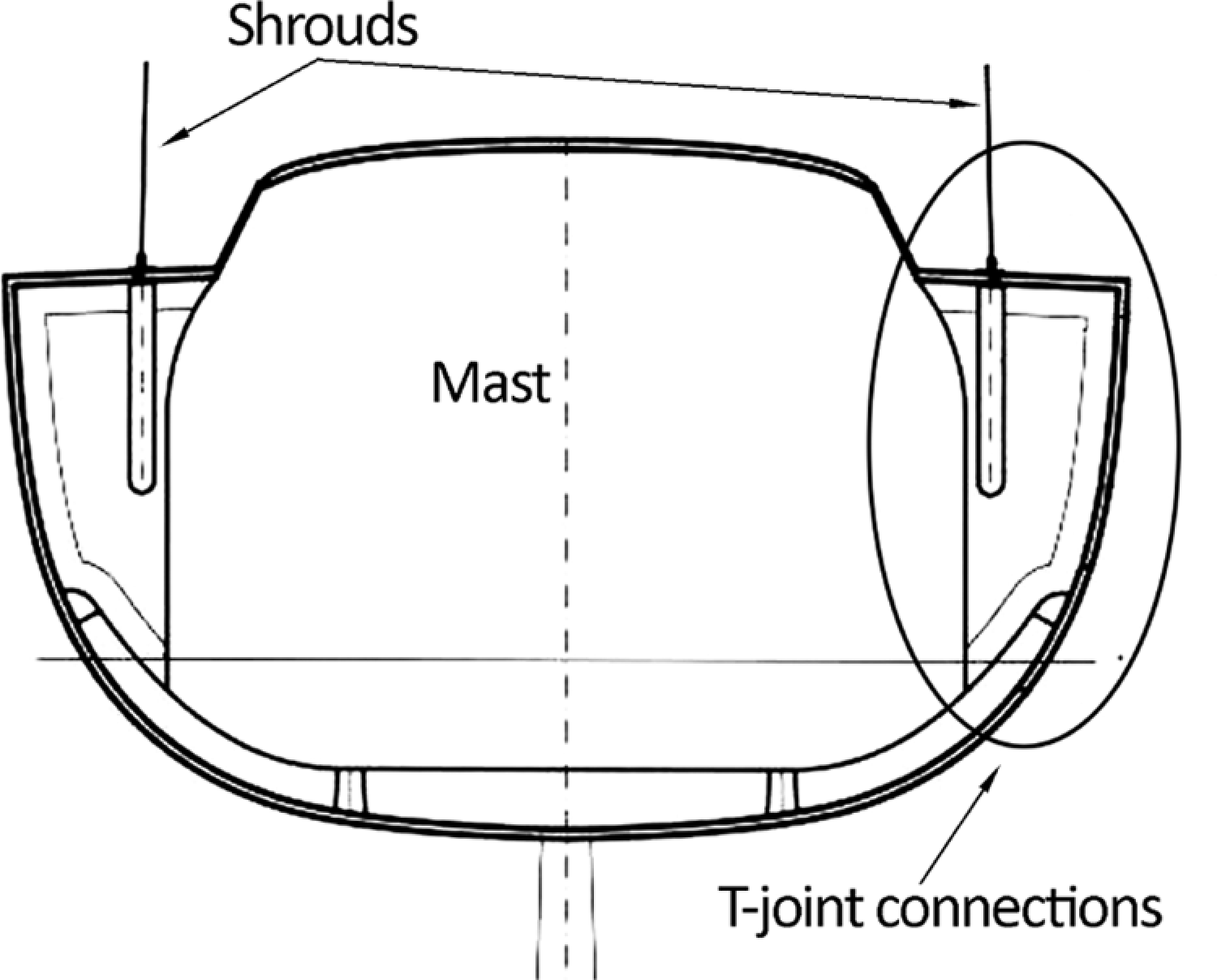
T-joints on board a sailing yacht, transverse section.
Experimental
All joints were manufactured with Twintex unprocessed commingled fabrics and preconsolidated panels, all details of which are included in Table 1. Fabrication sketches are shown in Figures 3 –6. A study of the influence of PP interlayers on the strength of lap joints was carried out using woven Twintex. A further study on the performance of PP-interlayered T-joints was carried out including nonwoven precursor materials, in order to compare their performance. It must be remarked that T-joints are denominated in the text as ‘woven’ or ‘nonwoven’. This refers only to the materials they were manufactured from, that is, woven and nonwoven. All the preconsolidated panels were originally vacuum formed in an electric oven on an aluminium flat tool at approximately 200°C, with a heating ramp, dwell time and cooling ramp of 60 min each. Processing temperatures well beyond the melting point of the resin (approximately 170°C) are commonly used in the industry to ensure good wetting and low void content in short processing cycles. From these panels and fabrics, three woven lap joints (with 0.30 mm PP, 0.15 mm PP and no PP interlayer) and five T-joints (combining 0.30 mm PP, no PP interlayer, single-skin woven and nonwoven materials and a balsa–core sandwich nonwoven joint) were manufactured, from each of which between five and seven samples were sliced for testing.
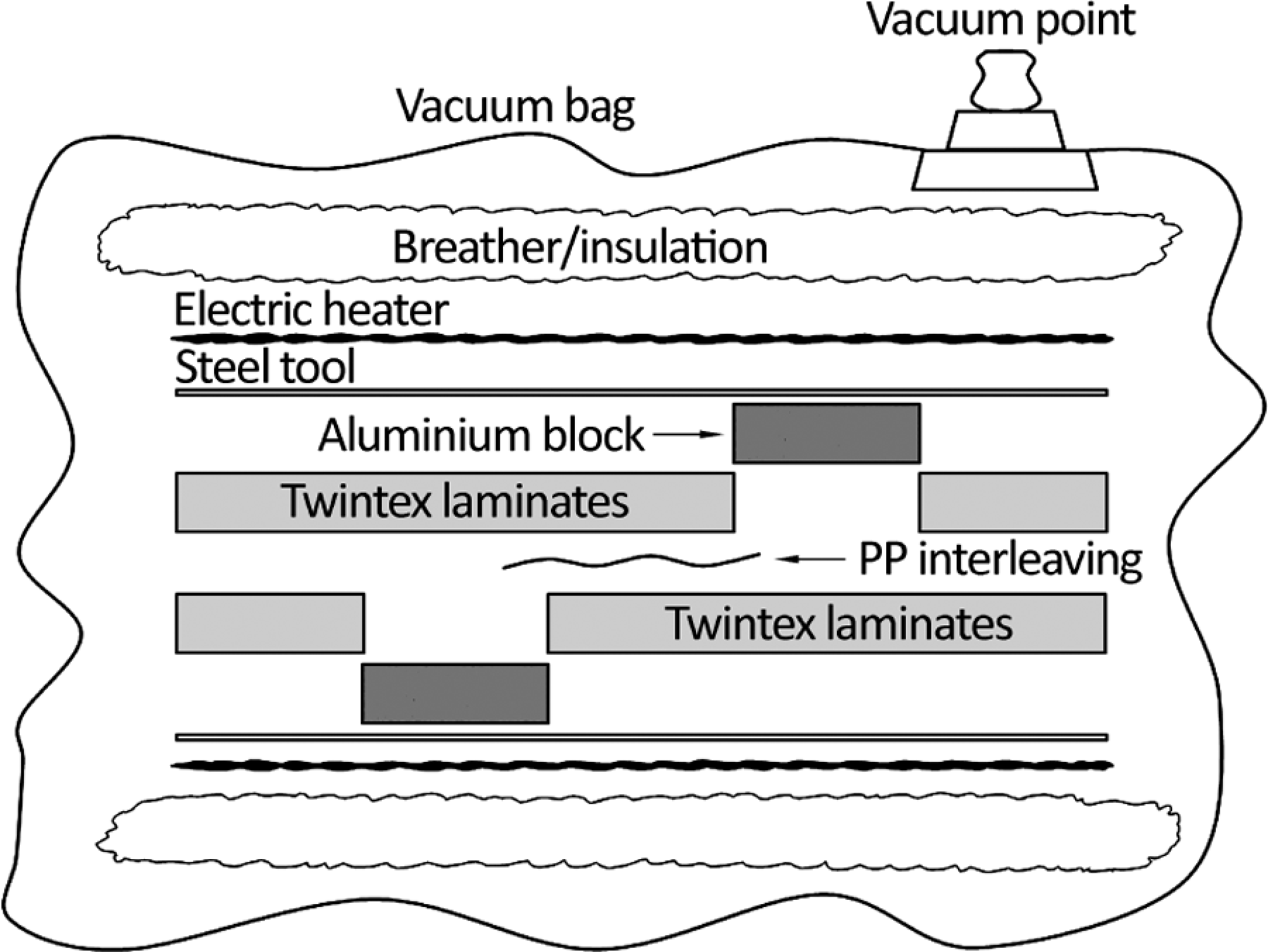
Typical arrangement for lap joints manufacturing.
Summary of materials and consumables used in the manufacturing of lap joints and T-joints.
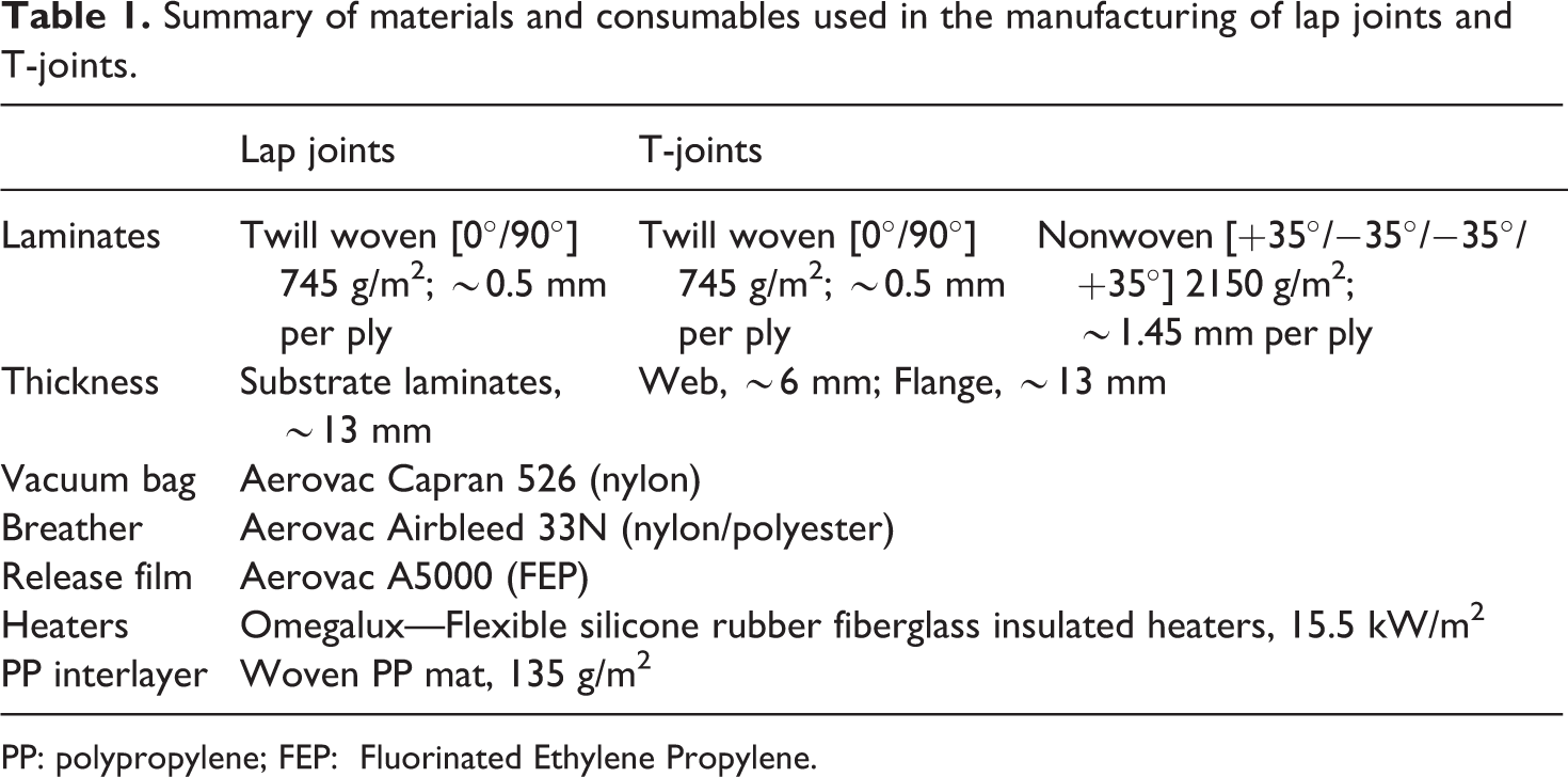
PP: polypropylene; FEP: Fluorinated Ethylene Propylene.
Once all necessary panels were manufactured, the joints were processed using local heating under vacuum. Heating was carried out with commercially available silicone rubber insulated electric heaters, which can be tailored to any size, facilitating scale up of the process. The vacuum forming process required the use of a breather layer to allow the air to be channelled out from all the laminates and provide thermal insulation and a release film to avoid adherence to the melted PP resin. This lay-up was placed into a vacuum bag and sealed by means of a pressure-sensitive adhesive sealant tape. Also, in order to evaluate the effect of a resin interlayer on the bond strength, up to two layers of PP woven mat were laid up on the joint interface of both lap joints and T-joints. The areal density of the PP mat was 135 g/m2, which is equivalent to a 0.15-mm PP film per layer. All used materials and consumables are summarized in Table 1.
For scalability and repeatability, one-sided heating was used for T-joints (Figures 5 and 6). This allows the processing of bulkhead–hull attachments and the other on-board T-joints to be carried out from the interior of the hull during construction. Thick lap shear test coupons were manufactured by heating from both sides (Figures 3 and 4), using two steel plates and two metallic blocks to prevent deformations during melt processing.
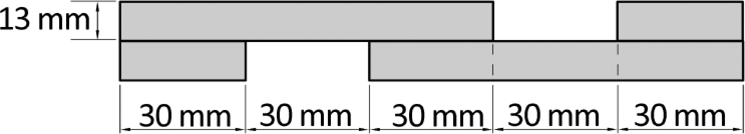
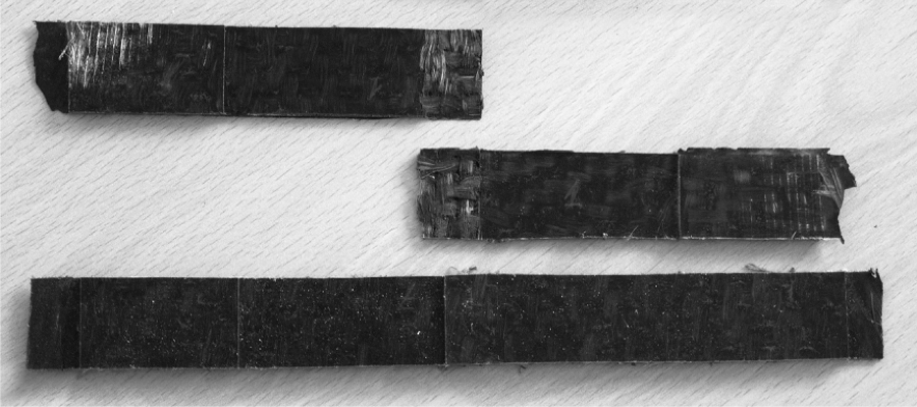
Finished lap shear coupon, typically 30 mm wide.
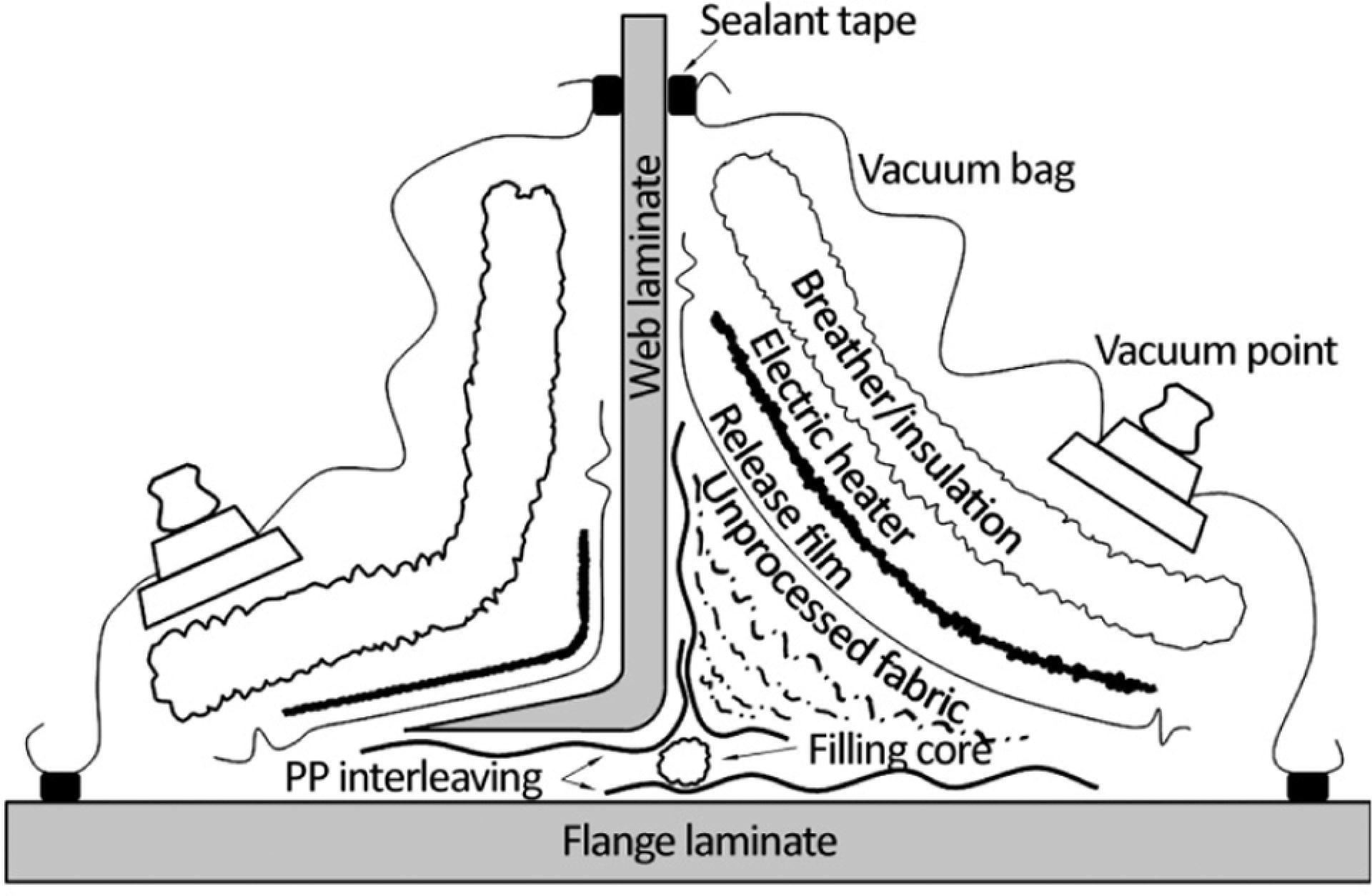
Typical arrangement for T-joint manufacturing.
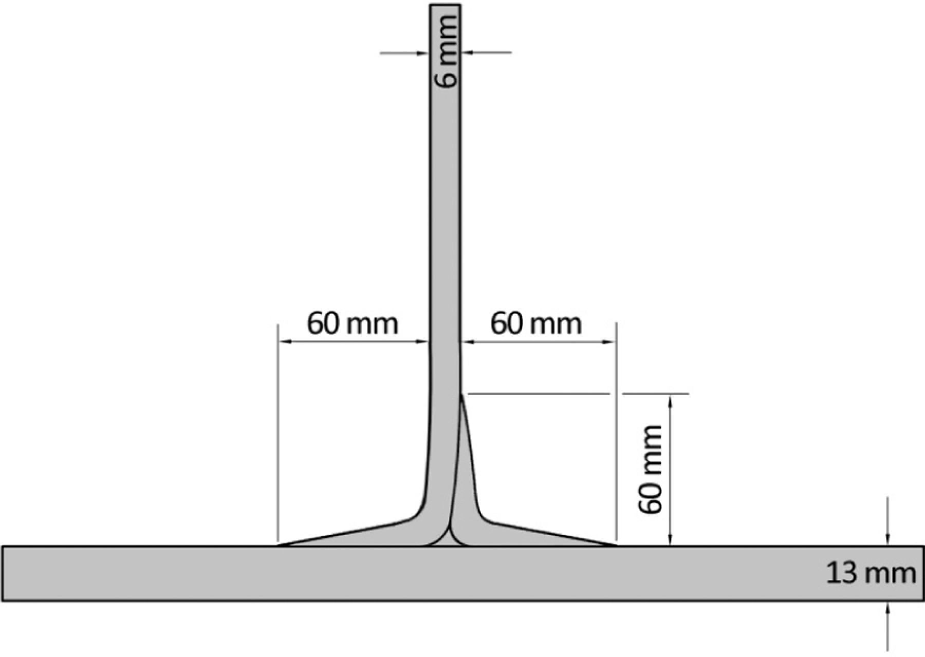
Finished T-joint sample, typically 20 mm wide.
All joints were manufactured and tested at approximately 22°C and 1000 mbar under laboratory conditions.
Lap shear
A first series of lap joints were manufactured with woven Twintex, with and without PP interlayer, in accordance with Standard ISO 4587 (Figures 7 and 8). This standard, conceived for rigid-to-rigid bonded assemblies, required a coupon thickness of 1.6 ± 0.1 mm and a bonded surface of 12.5 × 25.0 ± 0.25 mm. Samples were manufactured directly from unprocessed fabrics on a tailor-made steel mould that was heated from one side only, which proved suitable for their thickness.
Initial noninterlayered thin lap shear samples (ISO 4587).
Detail of noninterlayered thin lap shear sample (ISO 4587) from Figure 7.
No issues were found for the noninterlayered (plain) fusion-bonded samples, whereas PP-interlayered samples exhibited a remarkably stronger bond and developed very significant bending and peel forces around the lap joint. This was found to occur due to the low stiffness of the PP glass composite substrate when compared with metallic or thermosetting composite materials. Therefore, it was decided that a higher thickness was needed in order to decrease peel forces and in such a way to obtain a more accurate value of the shear strength. Hence, nonstandard 13-mm-thick samples were manufactured following the arrangement showed in Figure 3. Previously consolidated composite laminates were placed between two steel plates with appropriate aluminium blocks located in the gaps to prevent the resin from flowing out of shape. The plates were heated with flexible electric heaters and all the arrangements were covered with the breather-insulating layer and placed inside the vacuum bag. Additional external thermal insulation prevented heat waste and provided shorter processing times. Approximate processing conditions were similar to those of the composite panels the joints were made of: processing temperature of 200°C with a dwell time of 60 min and heating and cooling ramps of 60 min. These conditions were regarded sufficient to ensure full processing of the joint through the thick laminates. The dimensions of the finished samples are shown in Figure 4.
After processing, the samples were cut into 30 mm wide coupons, which provided a bonded surface of approximately 30 × 30 mm and tested under tension in a Dartec machine. The samples failed as required, with unnoticeable joint rotation near failure and therefore minimum peel forces developed.
Results and discussion
Tests results showed that PP interlayering significantly increases lap shear strength of woven joints (Figure 9) and shifts lap shear failure modes from cohesive in the resin plus fibre–resin debonding towards substrate delamination and fibre breaking (Table 2; Figures 10 and 11).
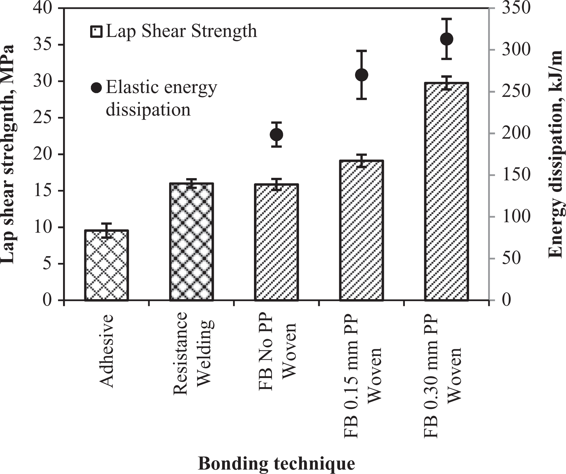
To further examine the nature of the PP interlayering reinforcing effect, the energy dissipated by elastic elongation in the bond line was calculated from tensile test data and plotted against PP layer content (Figure 9) for all lap T-joints, namely noninterlayered, with 0.15 mm PP interlayer and with 0.30 mm PP interlayer. All samples showed a typical load–displacement curve with an initial linear zone followed by fragile fracture. The elastic dissipated energy was assumed to correspond to the area below the linear zone of the stress–strain curve for each tested sample. This assumption was regarded as reasonable, because the measured tensile modulus of the samples was five times lower than that of the substrate material, meaning that most of the deformation energy was dissipated along the bond line.

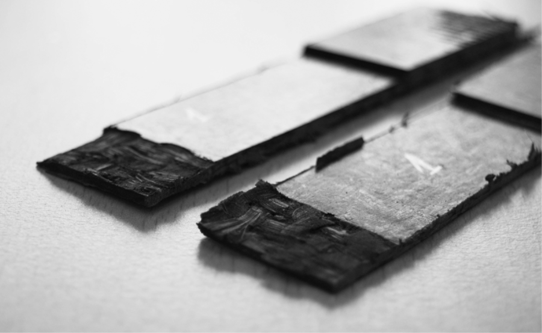
Fracture surface of noninterlayered thick lap shear coupons.

Fracture surface of thick lap shear coupons with a PP interlayer of 0.30 mm.
Failure modes recorded for lap joints.
PP: polypropylene.
Following these calculations, the elastic energy dissipated in the T-joints interlayered with 0.15 mm PP is 36% higher than that of noninterlayered joints. A further 0.15 mm PP layer increases energy dissipation by an additional 21%. Despite its apparently lower contribution to resilience, this second layer of PP leads to a threefold shear strength increase when compared with the first layer. Therefore, mechanisms other than elastic strain in the resin-rich bond interface must be considered to explain the increase in shear strength. A higher PP content on the joint line is likely to facilitate the movement of glass fibres during the joint processing, thus enhancing fibre wetting and mechanical interlocking. Fibres dispersed in such a way within this resin-rich region would improve the properties of the structural composite network, reducing stress concentrations and improving energy dissipation. This mechanism would also explain the observed change in failure mode from fibre–resin debonding into resin cohesive plus fibre breaking and occasional delamination (Table 2).
As shown in Figure 12, detailed observation of the fracture surfaces revealed certain ‘glass fibre glare’, namely the light being reflected on glass fibres, clearly distinguishable from the adjacent ‘matt’ finish of the PP resin. This fibre glare could not be seen with the added PP interlayers, which was considered to be evidence of reduced resin–fibre debonding.

Detail of ‘glass fibre glare’ (exposed glass fibre) found in noninterlayered lap shear joints.
It can also be seen that the strength values attained by interlayered lap joints are notably superior than those of joints made with woven Twintex® substrates, bonded with adhesives (25.4 × 25.4 mm joint surface and 2.5 mm thickness 18 ) and resistance welding (25 × 10–15 mm joint surface and 3–5 mm thickness 19 ) found in the literature (Figure 9).
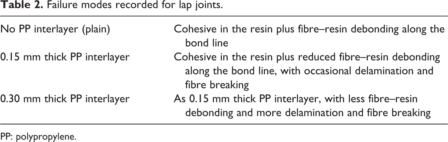
It is worth mentioning that the nature of a fusion-bonded joint line differs from that of a bonded joint. Instead of a well-identifiable adhesive thickness, the thermoplastic resin from the preconsolidated laminates flows along and through the joint line forming a continuum. The addition of a PP interlayer finds its place in the composite network creating resin-rich regions and resin pools, sometimes clearly defined but sometimes difficult to distinguish from the same phenomenon occurring at other regions of the laminate. Particularly, Figure 13 shows the detail of a PP-interlayered joint line. The bond line runs along a resin-rich region where small fibre bundles can be seen. By contrast, the area immediately to the left shows a close fibre packing, which is typical of noninterlayered joints, where the bond line is difficult to identify. Where noticeable, the resin-rich region extends for up to 0.5 mm on both sides from the joint line. Hence, the resin pools appear to fill naturally occurring gaps due to the woven distribution of fibre yarns.
Detail of the vertical joint line of a PP-interlayered T-joint.
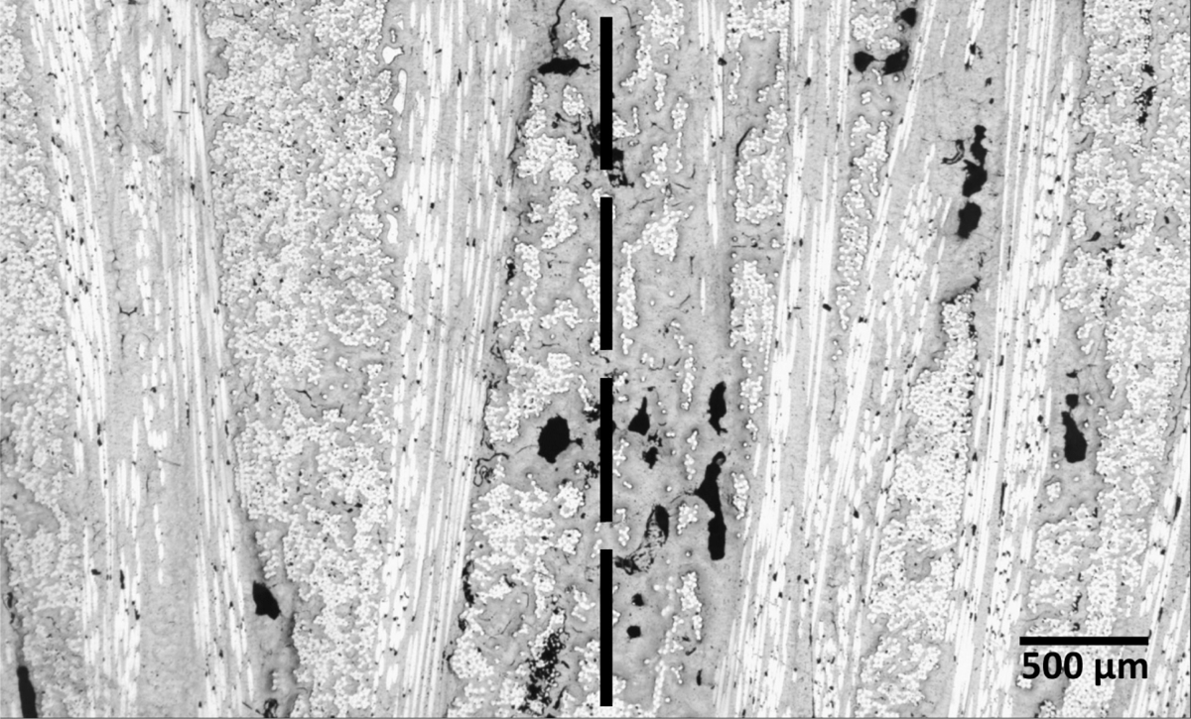
Lap shear strength data scatter appeared to follow a temperature-dependant trend, as seen in Figure 14. Some preliminary samples that did not consolidate completely displayed a clearly visible recrystallization line that followed an approximately parabolic shape through the laminate thickness. This line corresponds to an isothermal line, which indicates that the temperatures inside such processing rigs tend to follow parabolic trends, with its maximum in the centre and its minimum on the edges due to inevitable heat losses. Processing temperatures reached for the tested samples were estimated using a parabolic law from temperature measurements on the edges and on the electric heaters. Figure 14 shows that both strength and temperature distributions are remarkably similar, the variation in shear strength being in the range of 13%, corresponding to approximately 5°C processing temperature difference, even in the region of 30°C above the resin melting point. This unexpected difference may be attributable to the strengthening of the interlocking and fibre–resin debonding reduction phenomena mentioned above, influenced by the remarkable sensitivity of PP viscosity upon temperature. 21 Also, the cooling rates are probably lower at the joint centre than at the edge due to the mentioned heat losses (Figure 15). As reported for other thermoplastic resins, 22 this difference in cooling rates may affect the local crystallinity of the PP at the joint. Therefore, the observed joint strength difference is probably due to the combination of lower viscosity and higher crystallinity at the centre compared with the edges.
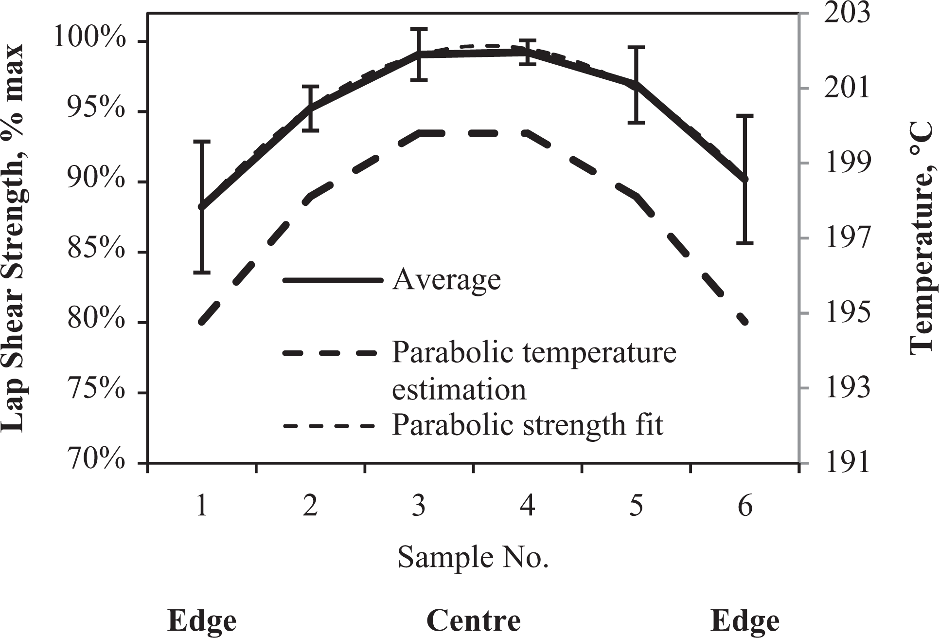
Lap shear strength and processing temperature variation along samples—corresponds to samples as shown in Figure 12.
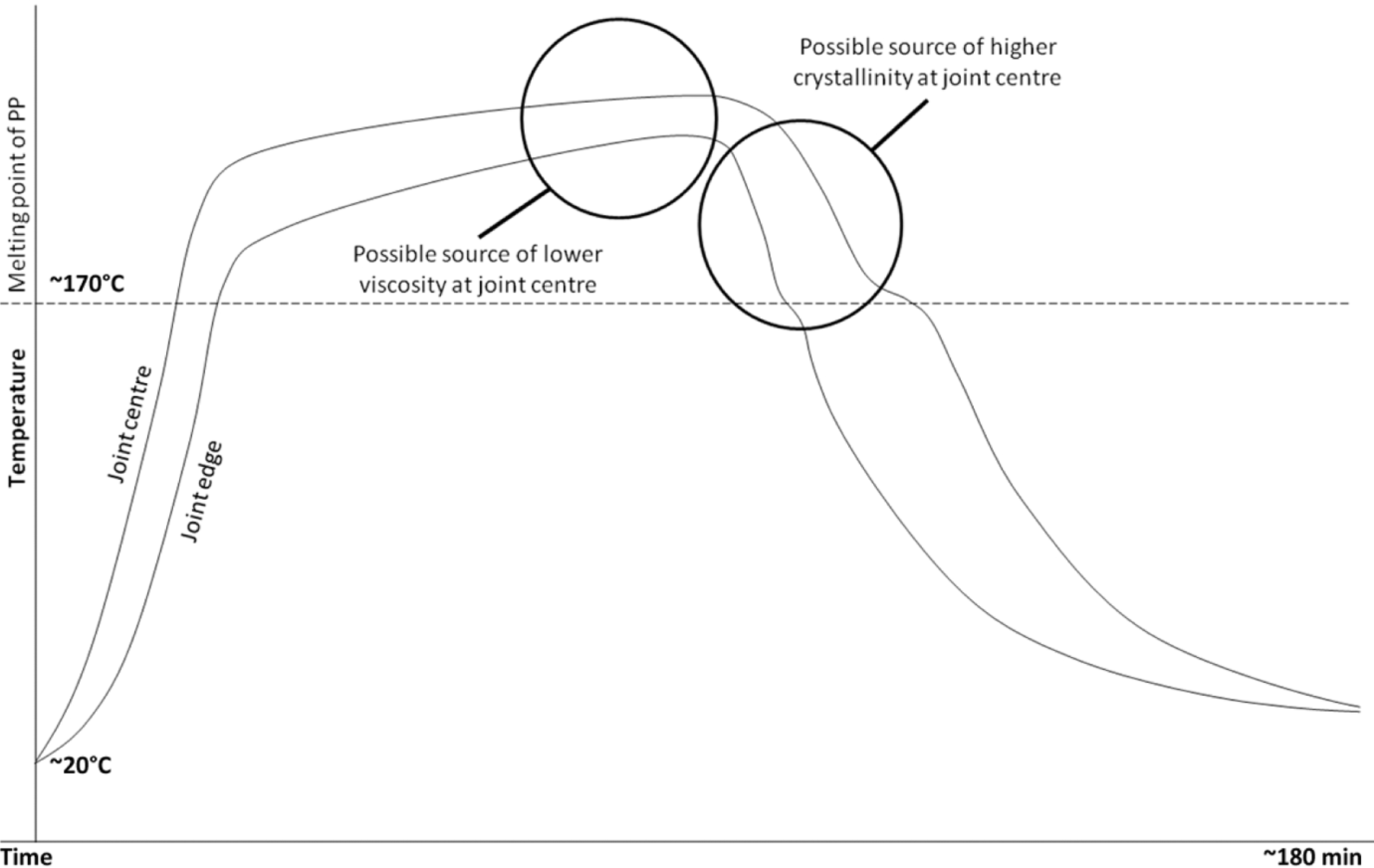
Estimated heating and cooling curves for centre and edge of LSS joints samples.
Research on resistance welding applied to thermoplastic composites 20 ,23 has shown that an optimal temperature and pressure condition can be found that results in a maximum shear strength beyond which higher temperatures may lead to excessive resin squeeze flow, thus degrading joint strength. However, since no decline has been recorded in these tests, the obtained results seem to leave room for potential process optimization with regard to PP interlayer thickness and processing temperature on fusion-bonded lap joints.
T-joints
Design
To date, the few existing thermoplastic composite boats make use of no-joints one-piece manufacturing, mechanical fasteners and/or adhesive bonding. 24 ,25 For this reason, the design of fusion-bonded T-joints suitable for boatbuilding was addressed prior to their manufacture and testing.
Without providing extensive detail on T-joint design, Classification Societies do establish minimum requirements for marine composite T-joints, mostly qualitative recommendations with limited data. Lloyd’s Register specifies overlapping thicknesses over 2 mm and areal weights of at least 50% of the lightest member connected to the joint. 26 The American Bureau of Shipping provides quantitative requirements for adhesives, with a 6.9-MPa minimum shear strength at a temperature of up to 49°C, 27 whereas Det Norske Veritas states a conservative safety factor of 5 in dimensioning T-joints. 28 Greene and Gibbs & Cox recommend 50 mm minimum overlapping in bulkhead–hull attachments, as well as avoiding close-to-90° sharp corner laminate construction, 29,30 which would lead to high void content and lower properties because of the lack of flexibility of commercial fabrics and bagging materials for composites (bridging).
Thicknesses and dimensions of the T-joints were chosen in accordance with these recommendations, as shown in Figure 6. In order to fully process the joint core, the distance between the heaters and the joint core needed to be small in order to reach processing temperatures in a reasonable time. This led to small curvature radii of approximately 6.5 mm, which may result in bridging-driven void formation.
Manufacturing
It was decided to manufacture five 25.5 cm long T-joints in such a way that the relevant comparisons amongst woven, nonwoven, plain and interlayered were possible. All specimens were cut into slices approximately 20 mm wide, which were subjected to a pull-out test in a Dartec tensile machine.
The T-joints comprised a preconsolidated web and flange, manufactured as stated in the Experimental section, and conceptually corresponding to bulkhead and hull of a small composite boat, respectively. The web incorporated a small flange itself, temporarily fixable to the hull in order to keep the bulkhead in place during the fusion-bonding process. A flexible heater was placed on this part of the joint, also covering a small area of the vertical web, to ensure that enough heat would flow towards the joint core. During processing, the covered material was remelted and fusion bonded to the substrate laminate (Figure 5). Additional unprocessed precursor fabrics were laid up to form a smaller L-beam on the opposite side of the joint and a second, larger flexible heater was positioned covering all the added fabrics. These co-consolidated during the bonding process, and as a result adhered to both the substrate flange and existing web. This heater arrangement prevented the web from reaching very high temperatures during processing. Temperatures beyond 230°C would squeeze out the matrix, with the risk of part movement during manufacturing and reduced thickness and mechanical properties. Conventional vacuum bags would also be sensitive to such temperatures.
The asymmetrical design offers the additional advantage that the joint does not have any vertical discontinuity on one of its sides, with potential benefits in case of asymmetrical loading cases, e.g. for tank bulkheads. This geometry works better for thermoplastic composites, as the resin reflow during joint processing would compensate for any dimensional inaccuracy. Given the reduced size of the joints, processing conditions were approximately those of lap shear coupons. Nevertheless, preliminary tests demonstrated that a dwell time of 30 min is sufficient to guarantee a good quality joint, albeit with approximately 10 cm at the ends of the specimens undergoing edge heat losses.
T-joints processed with this technique typically suffered from small deformations after processing (Figures 16 and 17) due to material flow and the absence of any tooling. Also, laminate deformations due to the release of residual stresses combined with asymmetrical heating were observed. This deformation, a well-known drawback of bulk heating fusion bonding, 6 ,7 was measured for the single-skin flanged T-joints. It was in the region of up to 5 mm vertical deflection over 300 mm base laminate length. However, a T-joint sample comprising balsa–core (Figure 20) overcame this problem. The sandwich core appeared to provide sufficient thermal insulation and a nonmelting supporting structure. These facilitated full melt of the hot skin while maintaining low temperatures in the lower skin, eventually showing no noticeable deformation after processing.

Initial major failure in a plain woven T-joint, initial crack above filling core—unprocessed fabrics added on left side.

Plain woven T-joint final snap off.

Initial side delamination in a T-joint with 0.30 mm thick PP interlayer—unprocessed fabrics added on left side.

Final collapse of the joint pictured in Figure 18.
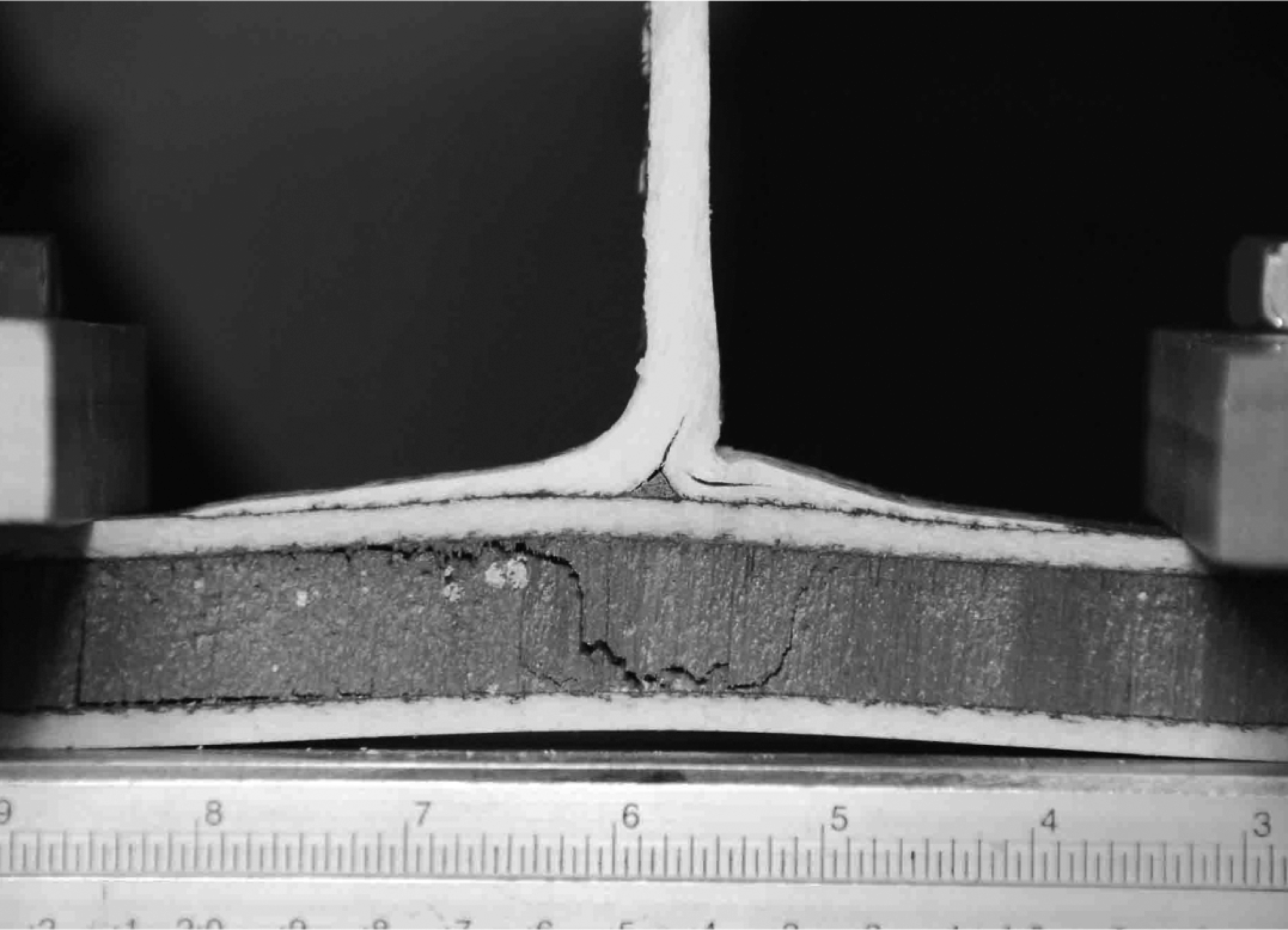
Detail on the simultaneous joint and core failure in the nonwoven PP-glass-balsa sandwich T-joint.
Once manufactured and sliced, the joints were placed on a testing jig (Figure 21), which was adjusted to a gripping span of 185 mm from centre to centre of the gripping blocks. The samples were simply held in the jig, avoiding any further bonding between the joint and the jig. However, it can be found in the literature that some authors have adopted adhesive bonding to the jig base. 13
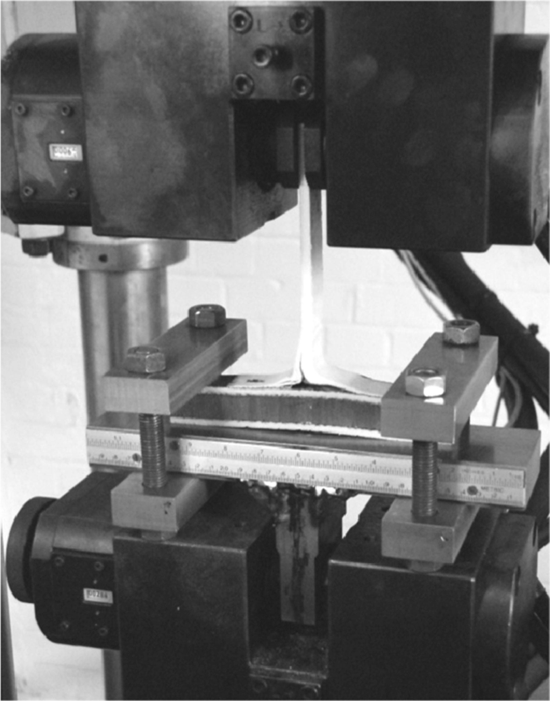
T-joint with nonwoven PP-glass-balsa sandwich substrate under pull-out testing.
This can facilitate the assessment of the joint mechanical behaviour by isolating the joint from the flange bending. In other cases, gripping conditions approximately corresponding to pinned 16 ,31 or fixed 17 ,32 were implemented on both ends. These different conditions can potentially deliver different strength values, due to the different flange deformations and energy dissipation mechanisms of the whole joint. In this study, a pinned-equivalent gripping was adopted because of the reduced bonding strength of available adhesives for PP-glass and because a real boat hull is rarely fixed on its surface. This fixture also takes into account deformations on the free-moving flange, which may lead to crack initiation and failure states that would be neglected otherwise.
Results and discussion
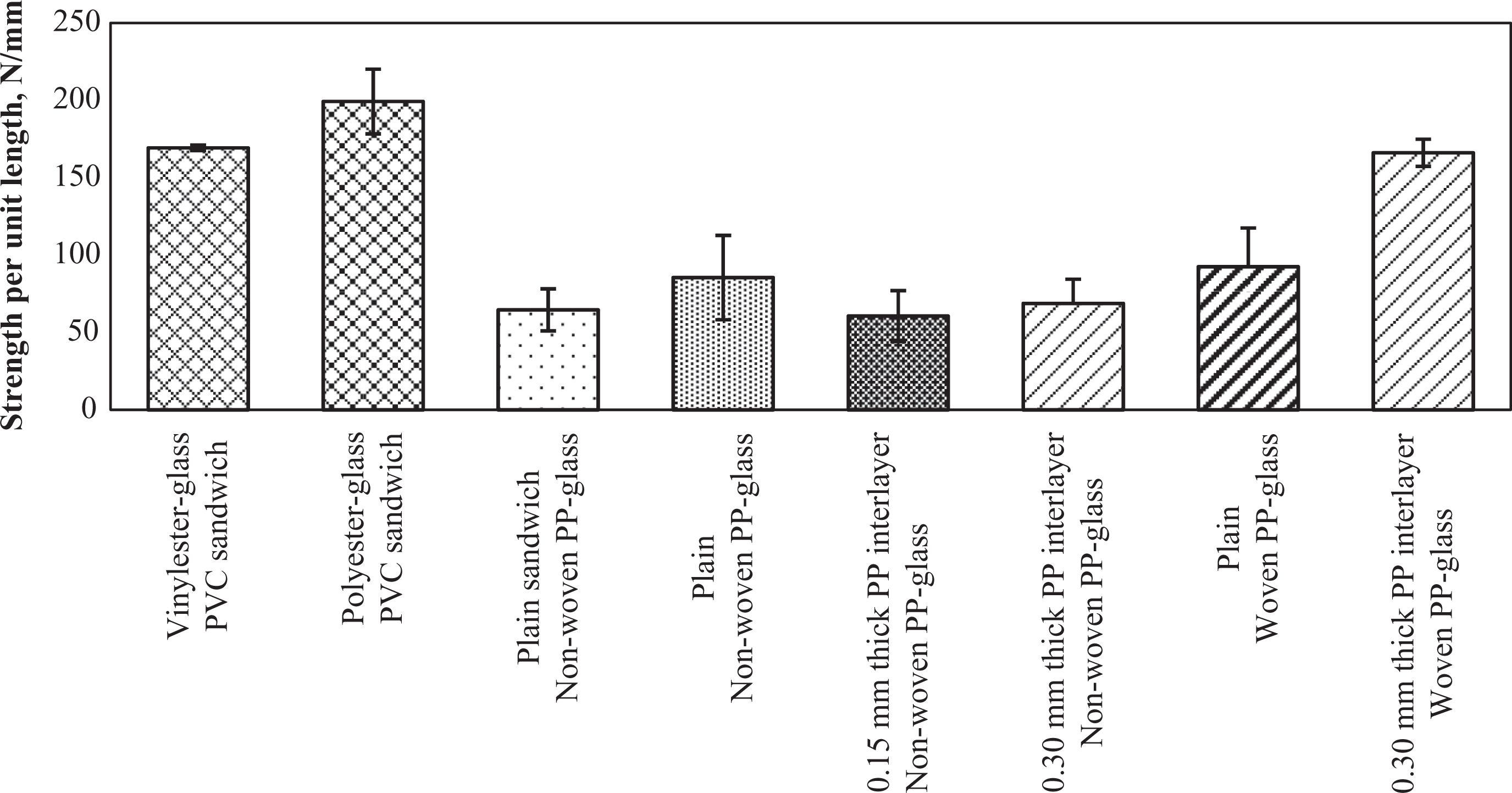
Pull-out test results revealed that the pull-out strength of T-joints manufactured with woven materials exceeded that of those made with nonwoven fabrics. All the observed failure modes (Table 3) consistently matched the observed higher strength values for the interlayered woven T-joints.
In contrast with the simple tensile behaviour of lap joint samples, T-joints showed a complex response to pull-out tests. Figure 22 shows graphs of the pull-out strength per unit length against the displacement for various samples. Shadowed regions show the curve dispersion for different types of joints, indicating that the additional PP interlayer significantly reduces data scatter, hence strength variability on woven joints, whereas it has a limited effect on the variability of nonwoven joints (Figure 23).
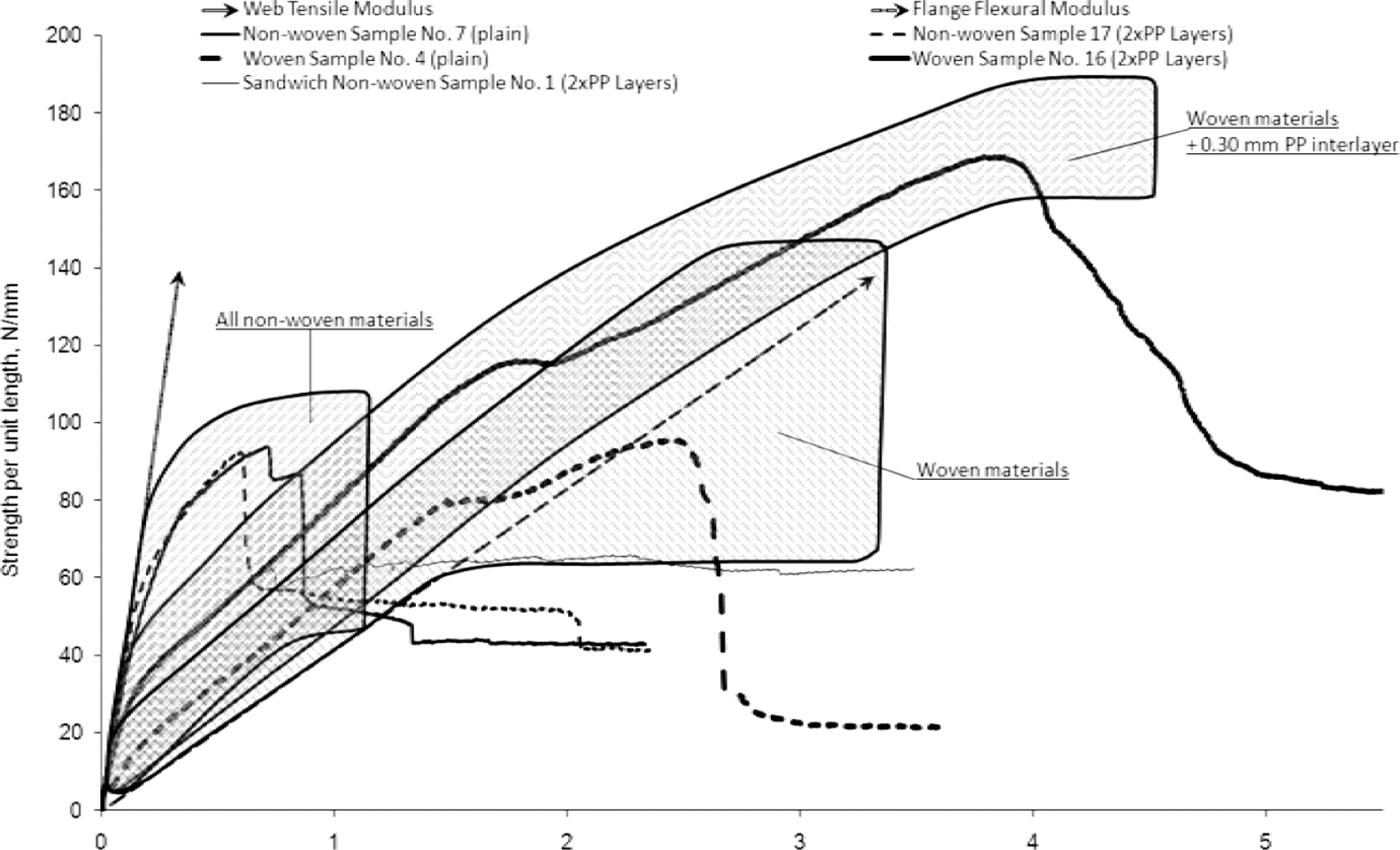
Typical strength–displacement graphs for interlayered T-joints manufactured with woven and nonwoven materials—shadowed regions show curve dispersion.
Failure modes in T-joints.
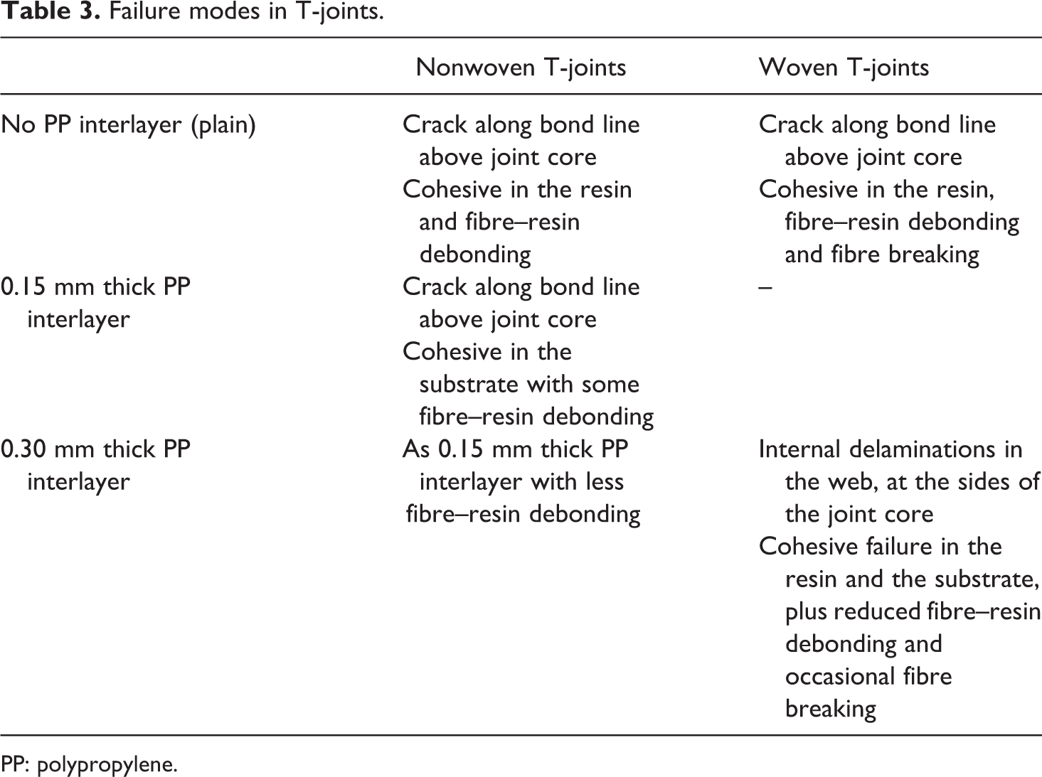
PP: polypropylene.
It can also be seen that woven joints are more resilient than nonwoven joints, a feature attributable to a higher ability of woven precursor materials to dissipate deformation energy, compared with their unidirectional counterparts. However, their strength per unit length is similar, as seen in Figure 23. By contrast, interlayered woven joints clearly outperformed all the rest in ultimate failure load per unit length and deformation energy dissipated.
Following the graphs, the displacement of the T-joints follows an initial linear path corresponding to the stiffness of the joint web, which is the vertical laminate with a thickness of 6 mm showed in Figure 6. The deformation taken by the joint web was always lower than 0.15 mm. After this initial deformation, the apparent behaviour of the joints followed a line parallel to that corresponding to the flexural stiffness of the flange substrate. The extent to which the joints combined these two initial deformation patterns showed a large scatter, especially for all nonwoven and also the noninterlayered woven joints. This scatter, attributed to material and construction variability and also to small differences in the geometrical constraints from the testing jig, was notably reduced for the PP-interlayered woven joints.
The addition of PP interlayers virtually doubled the strength of woven joints with a 0.30 mm thick PP interlayer. However, PP interlayers had no noticeable effect on the strength of nonwoven samples (Figures 20 and 21). These samples developed a visible crack along the bond line above the joint core, followed by cohesive failures in the substrate. A low peel interlaminar strength of the nonwoven substrates would explain the poor strength values recorded for these joints. Plain (noninterlayered) woven T-joints also showed an initial crack above the filling core (Figure 16), followed by a clean snap off along the bond line (Figure 17), indicating resin cohesive failure as occurred with nonwoven T-joints. However, PP-interlayered woven joints presented an initial delamination on the sides of the filling core (Figure 18) followed by progressive cracks propagation and finally substrate delamination (Figure 19). All observed failure modes are shown in Table 3.
The values of ultimate pull-out strength per unit length shown in Figure 23 exhibited a significant scatter for plain T-joints, attributable to joint quality variability due to local defects and bridging-driven porosity. This suggests that there is significant room for optimization in these T-joints. Local defects and porosity can be addressed by reducing the angle to which the L-beams need to adapt while consolidating and/or including more interlayers in between plies in order to increase the void-filling ability of resin-rich regions. This variability is nonetheless reduced in the case of PP-interlayered samples.
The improvement in pull-out strength and scatter reduction provided by the added PP may follow the same interlocking mechanism that is believed to improve lap shear strength. Figure 13 shows a detail of the vertical part of a T-joint which incorporates 0.30 mm PP interlayering. By comparing the joint line with the area immediately to the left, a greater fibre bundle movement can be seen. Despite high local porosity, this bundle distribution in local resin-rich regions may lead to improved fibre entanglement and hence higher interlaminar strength.
Local porosity along the bond line was measured by means of pixels counting, showing that the addition of a 0.30-mm PP interlayer reduced its value from 9% to 3%, respectively, as shown in Figures 24 and 25. Hence, the resin-rich bond line appears to have a filling effect, reducing local porosity to approximately one-third and homogenizing the void distribution. This resin-rich region allows for certain through-thickness fibre dispersion during joint processing which in its turn may help stress distribution and energy dissipation during pull-out loading. This mechanism would explain the observed interfacial failure shift into delamination in the substrate (Figure 19 and Table 3).
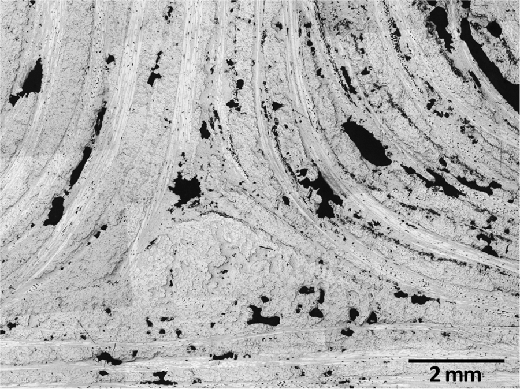
Optical micrograph showing high void content around the joint core in the case of plain woven T-joint.
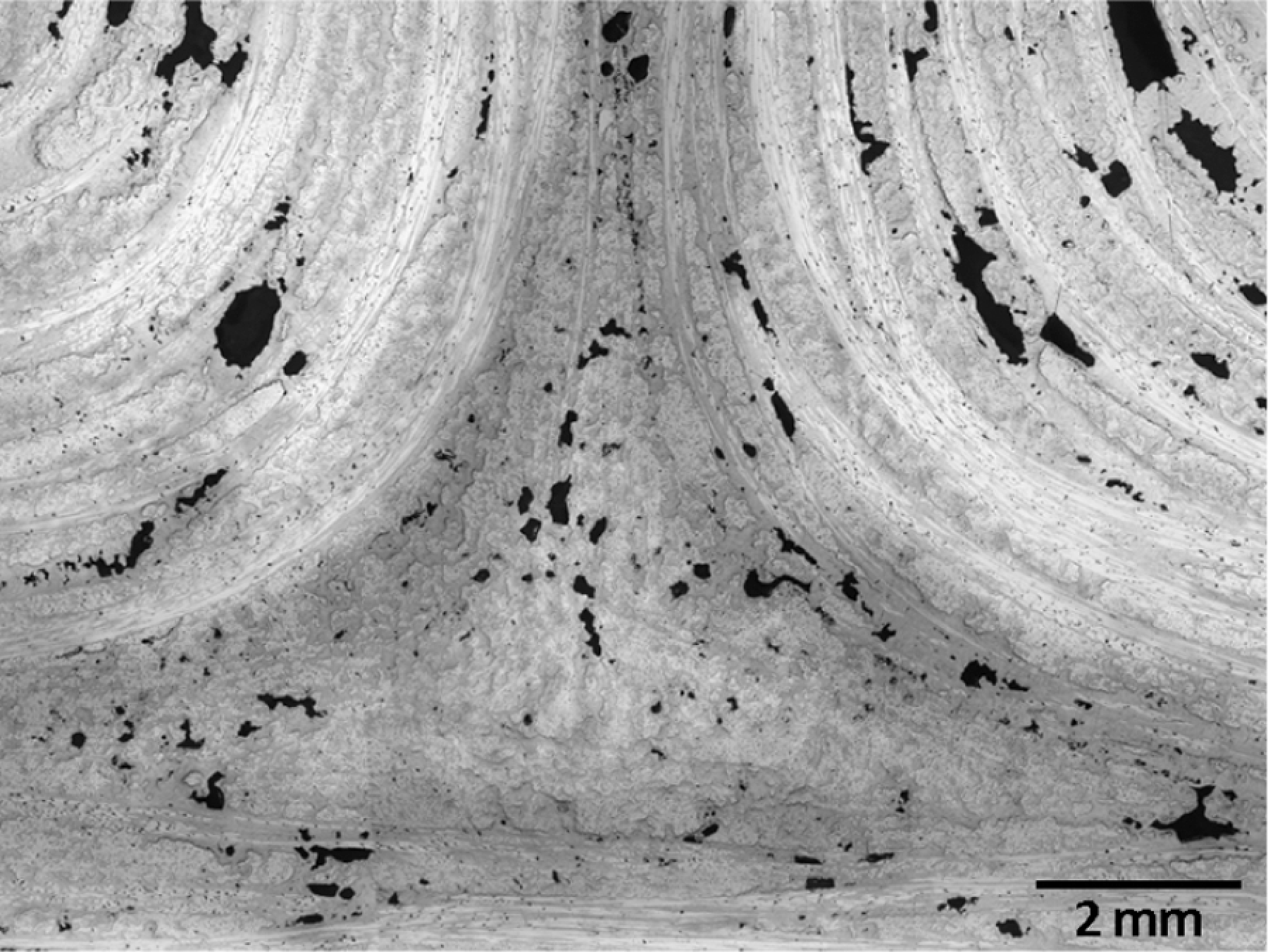
Reduced void content due to added PP interlayer (dark areas in the micrograph).
The strength of the samples obtained from the nonwoven sandwich T-joint (Figure 21) was comparable to that of single-skin nonwoven samples, as shown in Figures 20 and 21. The structural failure was simultaneous core shear, skin-core debonding and joint core crack initiation; thus, qualitatively validated the joint sandwich arrangement for pull-out loads. This is a good result, since the sandwich core provided a sufficient thermal insulation to prevent any noticeable postprocessing deformation. Therefore, it demonstrates that bulk fusion bonding is a structurally viable technique with dimensional control if appropriate insulation is present to protect the flange from thermal deformation due to asymmetrical bulk heating.
As mentioned above, one design recommendation which was not studied relates to the avoidance of sharp corners. The maximum resulting bridging-driven porosity was approximately 9% of the net volume as calculated from photomicrographs in Figures 24 and 25. Despite this local defect, the ultimate pull-out strength of woven-interlayered T-joints was close to the results of thermosetting structures tested under comparable conditions found in the literature (Figure 23). It is also worth noting that the thermosetting T-joints were significantly larger in many respects, particularly in bond surface size, which was 27% larger for vinyl-ester joints 16 and 67% larger for polyester joints. 32 Despite the differences in joint geometry, materials and size, it was found that the design and construction of the joints in this study, yet suitable for optimization, provide pull-out strengths that were comparable to those of existing and optimized thermosetting T-joints.
Conclusions
An experimental study on PP-glass composite lap joints and T-joints in the context of small boat manufacturing has been conducted, yielding the following conclusions:
A joining method intended for thermoplastic composite boats manufacturing has been developed, based on fusion bonding achieved by vacuum-assisted bulk local heating.
Results show that a 0.30-mm thick PP interlayer improves lap shear strength on samples made with woven materials by 80%, mainly by enhanced fibre wetting and mechanical interlocking, and, second, by elastic energy dissipation.
Nonoptimized lap joints manufactured from woven fabrics with this technique notably outperform known lap shear strength values for adhesives and resistance welding applied to the same substrates.
Asymmetrical bulk heating in T-joints induces noticeable warping on single-skin substrate laminates. Sandwich constructions, however, can also provide sufficient strength while maintaining shape after processing due to the insulating effect of the core.
Woven precursor materials are preferred over nonwoven fabrics for T-joint manufacturing because of the higher values of pull-out strength they deliver and the ability to increase pull-out strength by PP interlayering, probably due to their higher interlaminar and intralaminar strength compared with nonwoven materials.
Inclusion of a 0.30-mm thick PP interlayer improves the ultimate pull-out strength per unit length of T-joints made with woven fabrics by 80%. It also adds significant resilience and reduces scatter, improving repeatability.
Despite bridging-driven porosity of up to 10%, strength of T-joints is comparable with that of thermosetting known values.
These results demonstrate that bulk heating fusion bonding can be used as a joining method in the construction of small thermoplastic composite boats and that it provides sufficient strength compared with existing thermosetting joints.
Footnotes
Acknowledgements
The authors thank the preliminary work done by undergraduate student John Griffiths; the help of Museok Kwak from The Welding Institute (TWI), Dr S. Boyd from Southampton University and Dr M. Zarrelli from the Italian Research Council Institute of Composite and Biomedical Materials (CNR-IMCB); Christophe Ducret from OCV Reinforcements for data and material supply; and the staff at BAE Systems Surface Ships (formerly BVT Surface Fleet Halmatic) for their support.
Authors’ Note
Mariano E. Otheguy is a former researcher at NewRail, Newcastle University, Newcastle upon Tyne, UK.
Funding
This work was funded by the European Commission MOMENTUM Marie Curie Research Training Network, contract No. MRTN-CT-2005-019198.