
Abstract
This paper presents a study on the bending behavior of rectangular textile patch antennas including analytical modeling, full wave simulations, and experimental measurements. In the proposed analytical model, the textile patch antenna was treated as a laminated composite beam. Therefore, after locating the position of neutral axis considering the tensile modulus and the dimensions of each layer, the classic cylindrical cavity model was modified to predict the relation between resonance frequency and bending curvature, taking into account the patch’s elongation. Since the presented interdisciplinary analytical approach is associated with a set of simplifying assumptions, a full wave model was also utilized to study this effect. All the simulations were performed in two modes; patches with fixed and elongated dimensions. Finally the results of both models were compared with the experimental measurements and the effects of bending on the resonance frequency of textile patch antennas were discussed in more detail. The obtained results showed that some parameters including the direction of bending, substrate thickness, and mechanical properties of antenna’s components can alter the textile patch antenna’s behavior under bent conditions.
Keywords
Introduction
Smart materials and systems are undeniable reality of our world today. Alongside this trend, smart textiles have become a special area of interest in recent years. Smart textiles have heightened the need for interdisciplinary researches to answer complex questions which arise in these fields, more than any other time. Ability to sense and response to changing conditions or external stimuli, communicating, and power generating and storing are some of the basic characteristics of a smart material or system. It is worth to note that a smart system does not necessarily perform simultaneously all the functions that such a system can perform. Generally, the sensing function alone is taken as sufficient enough to constitute smartness in textiles [1]. Among the different functions of smart textiles, communicating is one of the most important capabilities that has led to emergence of new class of textiles called wearable antennas. These devices are responsible for wireless data transmission between the garment and the environment.
In general, wearable systems are faced with some challenges that mainly caused by their capability of being worn. Any wearable device has to satisfy several requirements concerning wearability. Comfort, light weight, breathability, and washability are common examples of these requirements. Obviously, antennas with planar and low weight configurations are more suitable for wearable applications. Since the microstrip patch antennas efficiently cover the above mentioned desires, most of the researches conducted have focused on these structures [2–4].
Regarding wearable antennas, we should keep in mind the four main challenges such as “body proximity”, “interconnections”, “harsh environments”, and “cloth deformations”.
Integrating the antenna into garment involves the interaction of electromagnetic waves with the body [5]. Due to rapid development of body-centric communication systems, the body proximity challenge has been addressed in numerous non textile researches [6,7]. However, there are also some efforts to study the effect of the human body on the performance of wearable antennas along with reduction of backward radiation from these devices into the body [8,9].
Wearable antenna is a device for sending or receiving data. Connecting the antenna to the other wearable devices that are responsible for providing or detecting such information is still an open problem. These devices may use textile transmission lines for their interconnections [10–12]. In this regard, making an optimal relation between electrical conductivity and typical textile properties such as flexibility is also an important challenge.
Regarding the harsh environments challenge, the degradation of wearable antenna’s performance under such conditions has been explored in some studies [13,14]. The results of these researches show that to ensure proper operation in such an environment, great care should be taken in designing and selecting antenna’s structure and components.
Despite all the issues mentioned above, the most probable challenge facing wearable antenna is the cloth deformations. A cloth endures a lot of deformations in daily use. These deformations range from simple (uniaxial extension, compression, single curvature bending) to complex (bagging, drape) ones. Such deformations can lead to changes in the wearable antenna’s shape and characteristics [15,16]. However, due to conformal capability, researches on nonplanar microstrip antennas has received much attention [17], but in comparison to antenna’s deformation, it seems the problem is different [18].
Among all the types of deformations, cylindrical bending is the subject of many studies on both conformal and wearable antennas. Particular examples for this nonplanar structure are the rigid patch antennas integrated into the body of an aircraft or missile. This is almost similar to the situation that occurs when the wearable antennas are wrapped around the human arm or leg. Previous researches conducted in this area involve a series of theoretical studies, full wave simulations, and experimental measurements. Among these, a considerable amount of theoretical researches are devoted to the rigid conformal antennas [19,20], while, the behavior of wearable antennas under cylindrically bent condition has been mostly studied experimentally or using computer simulations [21–26].
However, recently some attempts have been made to modify the analytical approaches for conformal antennas to analyze the wearable antennas under cylindrically bent condition [27], but, there is not still a more detailed understanding of this issue as a coupled mechanical–electromagnetic problem. In addition, the experimental data are rather controversial, and there is no general agreement about the effect of bending curvature on the resonance frequency of rectangular textile patch antennas. This paper seeks to overcome the mentioned gaps, where the wearable patch antenna is assumed as a multilayer structure, considering the tensile modulus of each layer. To achieve this goal, after locating the neutral axis (NA) of the antenna as a laminated composite beam, the extension occurring in the patch dimensions due to bending is calculated. Afterwards, the resonance frequency of the antenna under bent condition is estimated based on the cylindrical cavity approach, taking into account the patch’s elongation. Finally, the obtained analytical trends are discussed and compared with the results of full wave simulations and experimental measurements.
Experimental
Material characterization
Initial modulus and thickness of woven and nonwoven fabrics.

The electrical conductivity or surface resistivity of conductive parts and the dielectric constant of the antenna’s substrate are two main electrical features that influence on the patch antenna’s behavior. Since, the electrical surface resistivity of conductive fabrics is provided by manufacturer (about 0.05 ohm/sq); we focused on the measuring of dielectric constant of nonwoven fabrics.
From practical point of view, fibrous structures in simplest form are heterogeneous mixtures of air and fibers. Usually, in the case of mixtures, the overall dielectric constant is expressed in term of an effective value. Developing the high frequency applications of textile materials has revealed the need for high frequency characterization of fibrous structures. In fact, these properties may be quite different from the static ones. Several methods have been used for measuring high frequency dielectric constant of fibrous structures such as waveguide cavity and patch antenna methods [32,33]. Most of these methods are based on measuring the changes occurring in one parameter due to placing the unknown material in measurement setup. Multilayer microstrip transmission line is another method that can be used to study the dielectric constant of fabrics [34]. Microstrip line, in common form consists of a conductive strip on one side of a dielectric which has a ground plane on other side (Figure 1). In this method, the unknown material (fabric) can be placed under or over the microstrip line. Technically, this action will change the overall dielectric constant and the operating frequency of transmission line. These changes will be proportional to the dielectric constant of unknown material.
Single-layer microstrip transmission line.
For a chosen dielectric substrate thickness hl and a dielectric constant ɛl, the dimensions of single-layer microstrip line at 2.4 GHz (operating frequency of textile patch antennas) are calculated from the available closed-form formulas [35]. The characteristics of this line are shown in Table 2. Afterwards, samples were cut in suitable size and placed on the line and the measurements of parameter S11 were carried out using an HP 8510D Vector Network Analyzer (Figure 2). The right side of the line was terminated by a 50 ohm matching load. To fix the samples on the line, a foam layer was placed on them. This foam layer because of large amount of trapped air has no effect on the measurements.
Dielectric constant measurement setup. Characteristics of single-layer microstrip line.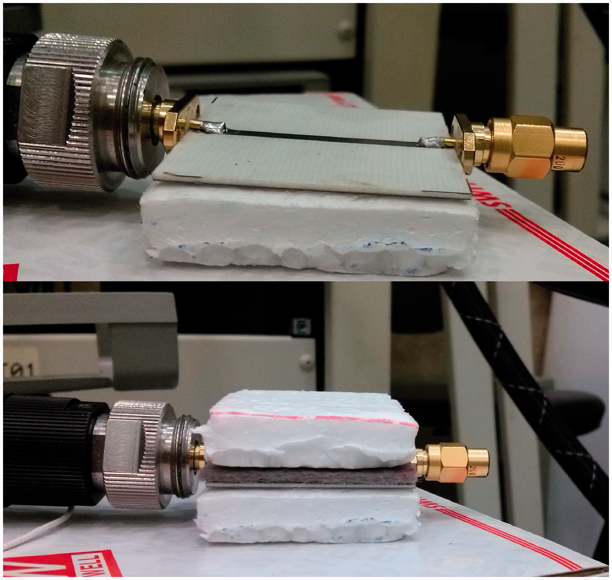

It is interesting to note that the behavior of a transmission line can be expressed by scattering parameters. S-parameters are actually reflection and transmission coefficients for a network of N ports. They indicate how well the line is matched with the input ports. The measurements were repeated five times for each sample. All measurements were performed at a relative humidity of 37% and ambient temperature of 21 ℃.
The overall dielectric constant of these two-layer structures was calculated from the first notch of the measured S11 curves (Figure 3) using equation (1):
S11 parameter of single-layer and two-layer microstrip line plus magnification.


Textile patch antenna design
A patch antenna in its simplest configuration consists of a radiating patch on one side of a dielectric substrate, which has a ground plane on the other side. The patch can assume virtually any shape, but conventional geometrical shapes are generally used to simplify analysis. There are various analytical techniques to analyze patch antennas. Each of these methods is based on some simplifying assumptions. Electromagnetic cavity model is one of the widely used approaches for evaluating the performance of patch antenna with conventional patch shapes such as a rectangle or circle. According to this model, the resonance frequencies of rectangular patch antenna are given by [37]:

In equations (4) to (6),
where:
Geometry of rectangular inset-fed patch antenna, (a) 3D view, (b) front view. Dimensions of the textile antenna prototypes.


Textile patch antennas fabrication
To fabricate a prototype textile antenna, we use two sets of fabrics including conductive woven fabrics as radiating patch and ground plane and nonwoven fabrics as dielectric substrate. Here, the samples were chosen in such a way that includes a range of different mechanical and electromagnetic characteristics. The first set consists of three kinds of commercials electrotextiles: pure copper polyester taffeta conductive fabric, copper + nickel coated conductive fabric, and copper + nickel coated mesh. For second set, three samples of needle punched fabrics were produced using regular and hollow polyester fibers. The weight fraction of hollow fibers in these fabrics was set at intervals of 50%.
The textile patch antennas fabrication was done using fusing technique. This method is generally used to produce multilayer textiles with fusible interlining using a combination of heat and pressure. Here also, the patch and ground fabrics were attached to a square layer of nonwoven fabric using a very thin layer of nonwoven double side fusible interlining. The fusing process was carried out in a HASHIMA HP-30 PS machine (temperature = 115℃, pressure = 4 bar, and time = 12 s). The conductive fabrics were placed over and under nonwoven fabric at warp/machine direction laying-up orientation. Moreover, all samples were pressed under the same bonding condition of fusing process and then their subsequent measurements (stress-strain curve, thickness and dielectric constant) were performed.
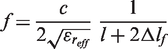
The designed prototype textile patch antennas were fabricated and then their resonance frequencies under flat and four different bending radii (100, 75, 50 and 30 mm) were measured. To bend the prototypes, they were placed and bent over the foam cylinders (Figure 5). Here also, the S11 parameters of the antennas were measured with an HP 8510D Vector Network Analyzer. The textile antenna was connected to the network analyzer by means of a 50 Ω SMA feed.
Bending cylinder with 100-mm diameter (bending along w direction).
Theory
In principle, deformation of textile antenna is a coupled problem which includes both mechanical and electromagnetic parts. However, mechanical loading can alter the electromagnetic characteristics of the textile antenna’s components such as the effective dielectric constant of the substrate, but in present study in order to simplify the analysis, it is assumed that the electromagnetic properties are independent of the mechanical deformation. So, the problem can be divided into two separate parts as follows:
First, in mechanical part, the textile antenna was considered as a laminated structure. Here, after locating the position of the NA, the strain occurring in the patch due to bending deformation can be estimated. Afterward, to determine the resonance frequency of textile patch antenna under bent condition, the patch’s strain is considered in solving the electromagnetic problem.
Mechanical problem
As it was previously mentioned, in present study, the lamination technique is used for manufacturing different textile antenna prototypes. Regardless of the adhesive between the layers, such structure can be considered as a three-layer laminated composite beam. The cross section of this structure when the antenna is bent along patch’s width direction is shown in Figure 6a (the feed line is neglected). Here as with non-composite beam, the NA is the location where the bending stress is zero. In the case of laminated structure, the position of the NA depends on the modulus and dimensions of each of the layer sections.
(a) Cross section of rectangular textile patch antenna when the antenna is bent along patch’s width direction, and (b) equivalent cross section.
Now, let us consider a laminate of thickness ht, consisting of three different layers (ground, substrate and patch) of moduli and thicknesses of Eg, Es, and Ep and hg, hs, and hp, respectively. One way for analyzing such structures is to replace the cross section with an equivalent area to represent the different modulus and size of other layers. After replacing the cross section, the problem of finding NA of composite beam is simplified to locating the centroid of a non-composite beam. The area scaling is performed using the ratio of modulus of second or third layer (substrate or patch) to modulus of first layer (ground) in y direction. The equivalent cross section is shown in Figure 6b.
The NA of equivalent beam can be found from the following relationship:

Substituting the scaled width in the respective layers of the cross section yields (Figure 6):

So, the location of NA relative to the bottom surface when the textile antenna is bent along width direction is given by:
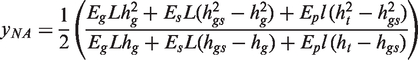
Similarly, when the textile antenna is bent along length direction, yNA is given by:

After locating the position of NA, the tensile strain occurring in patch’s width or length (depending on the direction of bending) can be calculated as follows:


Electromagnetic problem
The geometry of the bent rectangular textile patch antenna is shown in Figure 7. In this figure, the antenna is bent along width direction. The length of curved width is w + Δw, where Δw is the additional length to support the extension occurs in patch’s width due to cylindrical bending and it has been calculated in the previous section. In addition, θ is the angle suspended by curved edge and ϕ1 is the angle that formed by the right edge and the positive direction of the y axis.
Geometry of the cylindrically bent rectangular textile patch antenna: (a) 3D view and (b) side view (the feed line is neglected).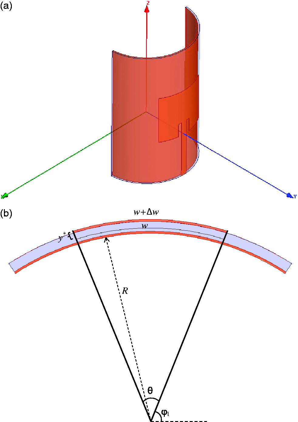
Like the flat patch antenna, the cavity method can also be used to analyze the cylindrically bent patch antenna [38]. In this approach, similar to the flat case, the region between the patch and ground is considered as a cylindrical electromagnetic cavity bounded by perfect electric conductors (PEC) on the top and bottom and perfect magnetic conductors (PMC) on the sides. The electric field inside the cavity satisfies the source free wave equation in cylindrical coordinate:
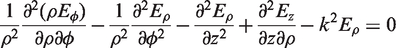


Using the method of separation of variables, we seek a solution to equation (13) in the form:
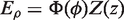
For the boundary conditions to be satisfied we require that:

So:


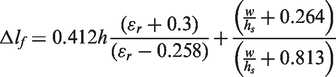
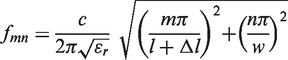
From equations (12) and (17), we derive the resonance frequencies as follows:

Also, from the previous section, we know that (Figure 7b):

Combining equations (18) and (19) leads to:

Since, patch’s length (l) is smaller than patch’s width (w), the lowest frequency of operation (when the antenna is bent along w direction) is given by, m = 0 and n = 1:

From the above analysis it can be concluded that if the patch antenna is bent along w direction, whether the patch’s width is stretched or not, the resonance frequency is not affected by curvature.
When the antenna is bent along l direction, in the same way, we obtain:
In this case, the lowest resonance frequency is given by, m = 1 and n = 0:

Equation (23) shows that bending curvature has a decreasing effect on the resonance frequency when the antenna is bent along l direction. As previously mentioned, above analysis is valid for thin substrate. In addition, to account for fringing effect, the values of dimensions and dielectric constant should be replaced by effective ones.
Full wave simulation
Analytical approaches are often associated with a set of simplifying assumptions. For instance, in above section we assume that the electric field only has a radial component (
In addition to the analytical methods in electromagnetic field, there are some other approaches which are known as full wave. In a full wave analysis, all the components of electrical and magnetic fields are considered. On the other hand, the complete set of Maxwell’s equations is solved numerically without any simplifying assumptions. Among different full wave simulator packages, HFSS is a powerful 3D full-wave electromagnetic simulator that employs the finite element method (FEM) and adaptive meshing. This simulator is utilized to analyze textile patch antenna under cylindrically bent condition. In the analysis process, the basic mesh element is a tetrahedron which allows solving complex geometry and shape.
Bent textile antennas have curved geometry that requires finer mesh to obtain more accurate results. In such geometries, the initial mesh does not cover completely the structure. This is due to the problems of the software to generate the mesh because the two surfaces are very close together. To overcome this weakness, HFSS provides a tool called mesh operations to approximate the initial mesh to the geometry by defining the surface approximation and the aspect ratio of the mesh. This modification leads to more usage of processor memory and more simulation time [39].
As theoretical section, the resonance frequency of textile antenna is studied under two bending conditions, bending along the w direction, as shown in Figure 8a and bending along the l direction (Figure 8b). In addition, all the simulations were performed in two modes: the dimensions of patch are fixed and the tensile strain occurs in patch due to bending deformation as it was estimated in mechanical problem section. In simulation process, the bending radius was set at intervals of 10 mm, from 25 mm to 215 mm.
Simulated inset-fed rectangular textile patch antenna bending (R = 100, 50, 25 mm), (a) bending along the w direction and (b) bending along the l direction.
Result and discussion
In previous sections, we presented the analytical and full wave models to evaluate the resonance frequency of rectangular textile patch antennas under cylindrically bent condition. In present section, first, the mentioned models are verified for large bending radii. Then, the measured values of resonance frequency of different prototypes under flat and bent conditions are compared with calculated ones from both models and the possible explanations are provided.
The analytical expressions to predict the resonance frequency of rectangular patch antenna under flat and bent conditions are presented in equations (4), (21), and (23). According to these equations, the difference between the resonance frequency of the flat and bent patch antenna depends on whether the change in patch’s dimensions occurs or not. Moreover, it is obvious that when the bending radius tends to ∞, the patch’s strain due to bending tends to zero. However, as mentioned earlier, when the antenna is bent along w dimension, the resonance frequency is independent of bending radius. As a result, when the bending radius tends to ∞, all of three mentioned equations lead to same values.
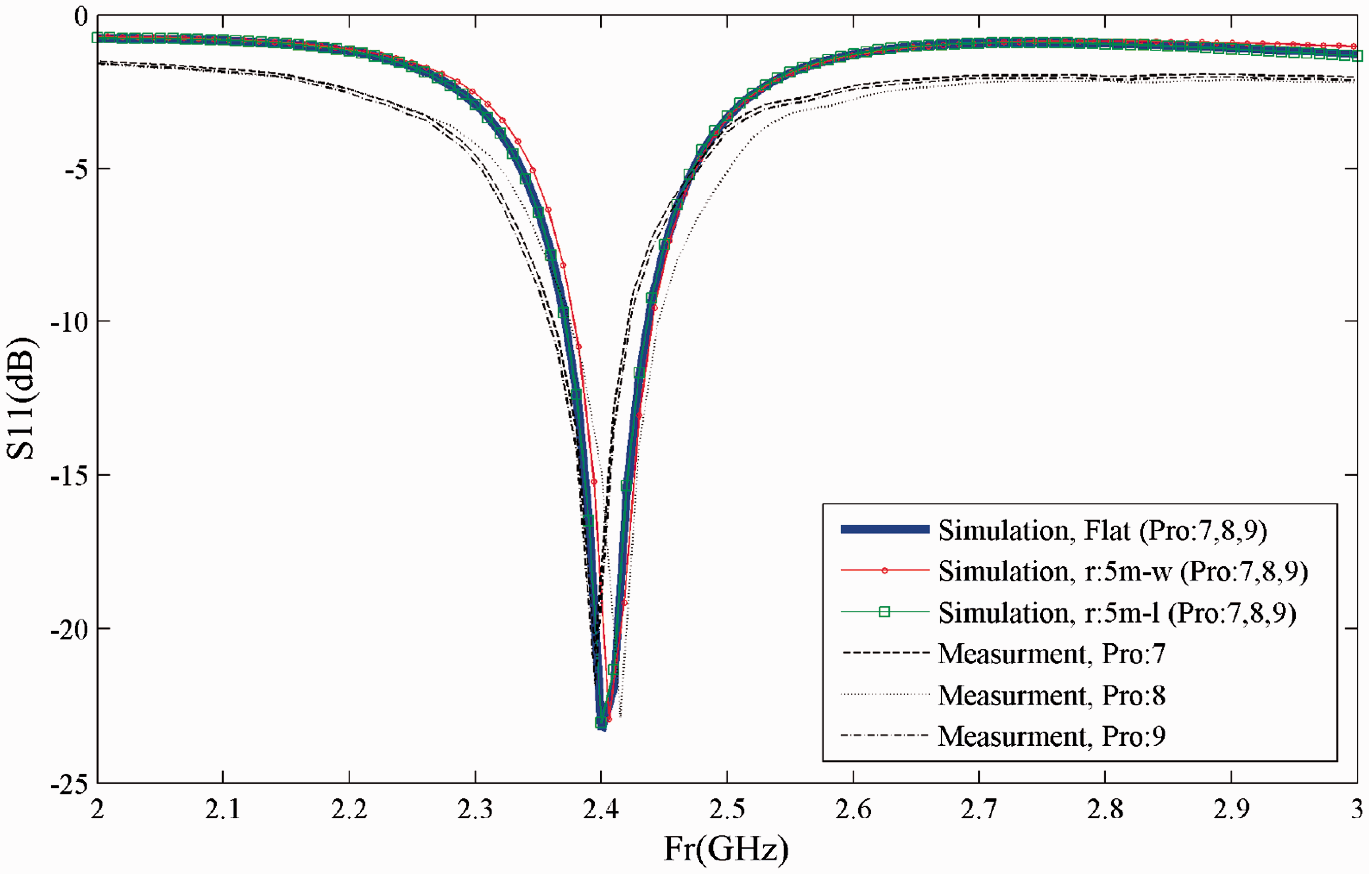
Similarly, to validate the presented full wave model, the resonance frequencies of cylindrically bent patch antennas under large bending radius (5 m) along the both directions (patch’s width and length) were compared with the results of flat antennas simulations and measurements. The measured and simulated S11 curves of different prototypes under flat and 5 m bending radius (only simulations) states are shown in Figures 9–11, respectively. As it can be seen in all three figures, the simulated curves for flat and bent antenna under large bending radius along both directions almost coincide. Furthermore, the simulated curves are in good agreement with the measurements.
Simulated and measured S11 parameter under flat and 5 m bending radius, prototypes: 1–3. Simulated and measured S11 parameter under flat and 5 m bending radius, prototypes: 4–6. Simulated and measured S11 parameter under flat and 5 m bending radius, prototypes: 7–9.

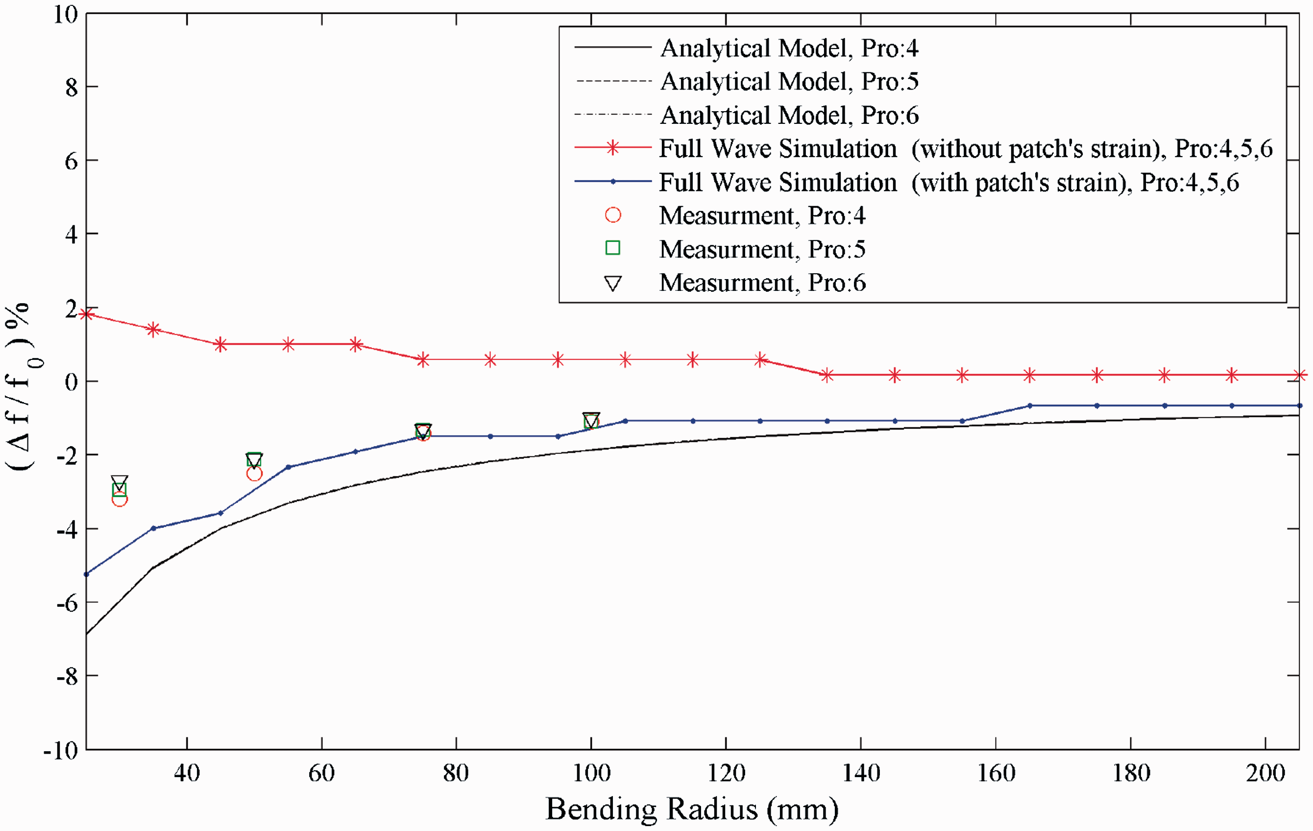
Figures 12–14 show the calculated (analytical model and full wave simulations) and measured percent change of the resonance frequencies versus bending radius when the antennas are bent along w direction. Similarly, Figures 15–17 show these trends when the antennas are bent along l direction. In these sets of figures, since the calculated patch’s elongations for the prototypes which have been constructed on the same substrate (1–3, 4–6 and 7–9) are approximately equal, the simulated values of resonance frequencies under same bending radii (full wave simulation with patch’s strain curves) for those prototypes become identical.
Percent change of the resonance frequency versus bending radius (bending along the w dimension), prototypes: 1–3. Percent change of the resonance frequency versus bending radius (bending along the w dimension), prototypes: 4–6. Percent change of the resonance frequency versus bending radius (bending along the w dimension), prototypes: 7–9. Percent change of the resonance frequency versus bending radius (bending along the l dimension), prototypes: 1–3. Percent change of the resonance frequency versus bending radius (bending along the l dimension), prototypes: 4–6. Percent change of the resonance frequency versus bending radius (bending along the l dimension), prototypes: 7–9.


According to the analytical model, when the antennas are bent along w direction, because the patch’s resonance length (l) is fixed, the resonance frequency does not change by changing the bending radius. This trend as shown in Figures 12–14 is in good agreement with the measurements and also both sets of full wave simulations (fixed and extended patch’s width).
But, when the antennas are bent along l length under same condition (patch’s dimensions are fixed), the results of full wave simulations differ from analytical prediction. In fact, the simulation results in this case indicate a slight upward trend in resonance frequencies for smaller bending radii. While, based on analytical model, for a patch antenna with fixed dimensions, the resonance frequency is not affected by bending. A possible explanation for this difference might be that the full wave simulations are more accurate than analytical predictions and in such analysis, all components of electromagnetic fields and also edges effects are precisely considered. The edge effects may lead to a slight change in the effective length of patch and the effective dielectric constant of substrate. Furthermore, the effect of feed line bending is also included in full wave simulations. All of these points can alter the results of simulations. Although a more detail explanation of this difference requires further investigations on conformal inset-fed rectangular patch antennas.
If we now turn to the experimental results, it can be seen that the trends of measured values when the antennas are bent along l length are similar to the analytical model and the second set of full wave simulations, where the patch’s strain is considered. To illustrate the differences between the analytical curves for prototypes 1–3, a zoom selection area has been also shown in Figure 15. The differences between analytical curves in Figures 16 and 17 are almost similar to Figure 15. As it has been mentioned earlier, bending of textile patch antennas along resonance length due to the patch’s strain leads to a downward shift in the resonance frequencies for smaller bending radii. Other conclusions drawn from Figures 15–17 are that the measured values are more closer to the simulation results than the analytical ones and by increasing the thickness of antenna’s substrate, the differences between measured and calculated values become greater for smaller bending radii.
To shed more light on the bending behavior of textile patch antennas, we have to separate all the effective factors. Based on equations (4), (21), and (23) and regardless of environmental conditions, there are two main parameters that determine the resonance frequency of any rectangular patch antenna under flat or bent state; the effective dielectric constant of substrate and the effective patch dimensions. As it was mentioned earlier, the dielectric constant of substrate and air is often different, so the wave is propagating in an inhomogeneous medium. In addition, because of limited dimensions of the patch, the fields at its edges undergo fringing. These two sources of error can be resolved by considering the effective dielectric constant of substrate (
Furthermore, bending the textile antennas leads to wrinkle the ground plane fabric. The magnitude of this effect depends on the elasticity of textile antenna’s components, the thickness of the dielectric substrate and the curvature. Although, this effect has been also mentioned previously [24], but, the experimental evidences show that it is not limited to the non-stretchable patches.
Summing up the results, it can be concluded that the bending behavior of rectangular textile patch antennas is a function of bending axis, electromagnetic characteristics, and mechanical properties of antenna’s components. Moreover, the bending is also associated with patch’s elongation, substrate compression, and ground plane wrinkling.
Conclusion
In this paper, an interdisciplinary research was conducted to evaluate the effect of cylindrical bending on the resonance frequency of rectangular textile patch antennas. This aim was followed in three phases, analytical modeling, full wave simulations, and experimental measurements. In the proposed analytical model, the textile patch antenna was treated as a laminated composite beam and this approach was incorporated in cylindrical electromagnetic cavity model. In the next step, two sets of full wave simulation were carried out with fixed and elongated patches. Finally, these predictions were compared with experimental measurements. Based on the results, the following conclusions can be drawn:
The analytical model showed that the mechanical properties of antenna’s components can alter the effect of bending deformation on the resonance frequency of the textile patch antennas. The experimental results also showed the same trend. Full wave simulations almost confirm the obtained analytical trends. However, there is more agreement between the simulations (with patch’s strain) and experimental results than analytical ones. Direction of bending has a significant effect on the bending behavior of textile patch antennas. The bending is also associated with substrate compression and ground plane wrinkling. The magnitude of these effects depends on the elasticity of textile antenna’s components, the thickness of the dielectric substrate and the curvature. For thicker substrate and smaller bending radius, these effects lead to further discrepancies between the theoretical and experimental results.
Footnotes
Declaration of Conflicting Interests
The author(s) declared no potential conflicts of interest with respect to the research, authorship, and/or publication of this article.
Funding
The author(s) received no financial support for the research, authorship, and/or publication of this article.