
Abstract
3D structures for composites, and especially 3D woven preforms use, is growing because of high-performance fibres improvements, field diversification and applications complexity. Critical industries like the air-space industry need a perfect control of processes and products’ final properties. Among other 3D weaving techniques, multilayer weaving is interesting for the diversity and complexity of possible 3D structures. A new Jacquard shedding technology called UNIVAL 100 which can be used with multilayer weaving, has appeared few years ago and uses actuators instead of the traditional Jacquard hooks. It is synonym of great improvements, as such a technology should enable controlling perfectly the way yarns are moving during shedding. The aim of this paper is first to describe their operating mode. It is our basis for a design of experiments development, the purpose of which is to experimentally determine the effects of UNIVAL parameters on process quality, in the case of high-density multilayer woven fabrics (which we will further call HDMW fabrics).
Keywords
Introduction
3D woven reinforcements for high-performance composite materials may be produced thanks to several techniques. Some of them like non-interlaced 3D processes or noobing [1, 2], or 3D weaving process [3] produce massive but simple shaped woven structures, with a very specific equipment [2,3]. Multilayer weaving process also provides large structures as soon as the number of layers is high enough. Its advantage is to be realizable with conventional shedding machines [4–6], with looms which may be specifically adapted for multiple layer bounding, especially at the tensioning and warp feeding stages [6,7]. Multilayer structures study is interesting because it is one of the most widely used 3D techniques. The study of this kind of structures is also relevant as multilayer fabrics may have many warp yarns interactions which are a source of yarns and structure damages.
Indeed, a major issue of high-density 3D woven preforms is yarn fibrillation [7–10]. This phenomenon, increased because of density, is a cause of final products mechanical properties loss. Friction between yarn and loom elements or between neighbours yarns tend to cause fibrillation which consists in mono-filaments breakage into shorter fibres. As shown in Figure 1, this phenomenon forms free fibres [11] (Figure 1(a)) and fibrils clusters [12] (Figure 1(b)) which may hamper a correct shedding [12,13]. Few papers have been published about the specific question of shedding warp damages, even if it is a major issue for high performance yarns for composites’ woven reinforcements. Indeed, these studies [7–10] focus either on yarns friction on loom and warp feeding devices parts or damages on brittle materials due to their bending. It has been observed that yarns movements are a great source of fibrillation [13]. This research comes within the general scope of industrial textiles weaving process improvement, by finding weaving settings which reduce warp damages, yarn position errors and shedding difficulties. This objective will be reached by carrying out theoretical hypotheses and experiments on Jacquard shedding parameters.
Several illustrations of fibrillation: (a) broken free glass fibrils; (b) free polyester monofilaments and clusters.
For multilayer woven fabrics, Jacquard shedding systems especially enable very complex and variable structure shapes [13], as their warp yarn individual-driving principle permits any weave pattern. However, those classical mechanisms have several limitations: shedding kinematic is constant because of mechanical movement transfer from the loom and shed geometry is generally flat. A particular Jacquard system, equipped with actuators driving yarns instead of mechanical hooks, is the Stäubli’s [14] UNIVAL 100 Jacquard shedding machine. Besides single yarn position control, it also provides original shedding parameters as actuator may change movement, time phase and shed geometry.
Methods and materials
Warp feeding and tensioning system
The use of a Jacquard shedding mechanism, thanks to the diversity and complexity of weaving pattern it enables, seems to go together with the use of creel which lets each yarn evolving individually. In our creel structure (Figure 2(a)), each bobbin is braked on its flanges in order to preserve yarns from abrasion. Weight hooks visible in Figure 2(b) are used in order to call back the excess of warp yarn during shedding movement and maintain tension. Thus, woven structures may be imbalanced and as complex as needed.
Warp feeding system: (a) creel back view; (b) weight hooks.
Jacquard UNIVAL parameters general description
The shedding system is a UNIVAL 100 Jacquard shedding system which drives individually each warp yarn thanks to Jacquard string, as shown in Figure 3. Stäubli have set four distinct parameters which can be set by the user on the UNIVAL interface. As it is described further, their use may be crucial by locally or globally reducing density. This section focuses on each UNIVAL parameter general setting and behaviour in order to put forward some hypotheses about their effects on warp yarns abrasion.
Side view of shed: eyelets are moved thanks to Jacquard strings according to the UNIVAL settings.
Shed phase difference
It comes historically from cams phase setting in cams shedding devices but here consists in setting a time gap between the 0° crossing reference time and a yarn crossing time. Thanks to this parameter, each yarn may start moving later or sooner than reference time or neighbour yarns. It might facilitate movement at shedding beginning and crossing time, as density can be reduced progressively and very locally according to the settings chosen.
Shed profile
This parameter corresponds to yarn movement, i.e. yarn vertical position during shedding according the shedding time cycle. Its corresponding mechanism would be cam shape in cam shedding systems. As any profile may be chosen among several available, the movement and speed of yarns can be adapted to the material, pattern and density in order either to preserve yarns or to ensure crossing.
Close shed profile
It allows yarns staying in up or down position for several picks, to move, however. Once such yarns have moved near shed centre, they will return to their initial position before weft insertion. Consequently, yarns making shedding can be accompanied by other yarns which are given a movement instead of being static and blocking them. Such a parameter may be very efficient at shedding starting.
Shed geometry and geometry offset
These parameters have a very wide range of settings. As UNIVAL actuators can raise yarns thanks to their pulley where Jacquard strings will be winded up, any shed geometry may be considered. Moreover, an offset may be added over the basis geometry. Offset consists in setting a regular height gap, so that the two layers of the opened shed can be split and density lowered.
Finally, actuators may get information back about shedding and warp state. The UNIVAL errors detection system can detect a yarn out of the position tolerance threshold and warp overstrain or low strain value due to high density.
The aim of studying such a new technology is to set a general portrait of the effects of the previously described UNIVAL 100 parameters on weaving quality, as it represents a huge potential for improvements for high-density multilayer woven (HDMW) fabrics. Appropriate shedding parameter settings for 3D fabrics weaving should eliminate the major part of fibrillation and filaments damages, whatever weaving pattern or density may be. Thus, it should ensure a faster weaving and quality needed for industry production.
Design of experiments development
Many parameters are crucial for multilayers weaving; they are linked to the pattern and fabric such as bonding and weft or warp densities, to the yarns used (materials, yarn count, mono- or multi-filament) or to the type of devices and techniques (loom, winding, etc.). All of these have been studied or at least approached. Surprisingly, the shedding stage is not much studied and understood in terms of fibrillation generation. Nevertheless, Mc Hugh [13] has shown that proper shedding parameters settings could reduce drastically yarns damages. As we have seen in the previous Jacquard UNIVAL parameters description, this technology is very efficient for moving and positioning yarns. With all other variables being more regularly studied, we have chosen to focus on shedding parameters settings.
Design of experiments of four parameter entries with two levels each.


Parameter level selection
Figure 4 illustrates the effect of phase difference setting with a gradual delay of yarns. As it may be seen between time t1 and time t4, a progressive start of yarns should reduce locally yarn density and ease motion start. The two values set for low and high levels correspond to the time gap while the last yarn starts moving.
Illustration of the effect of a progressive delay on yarns movements start.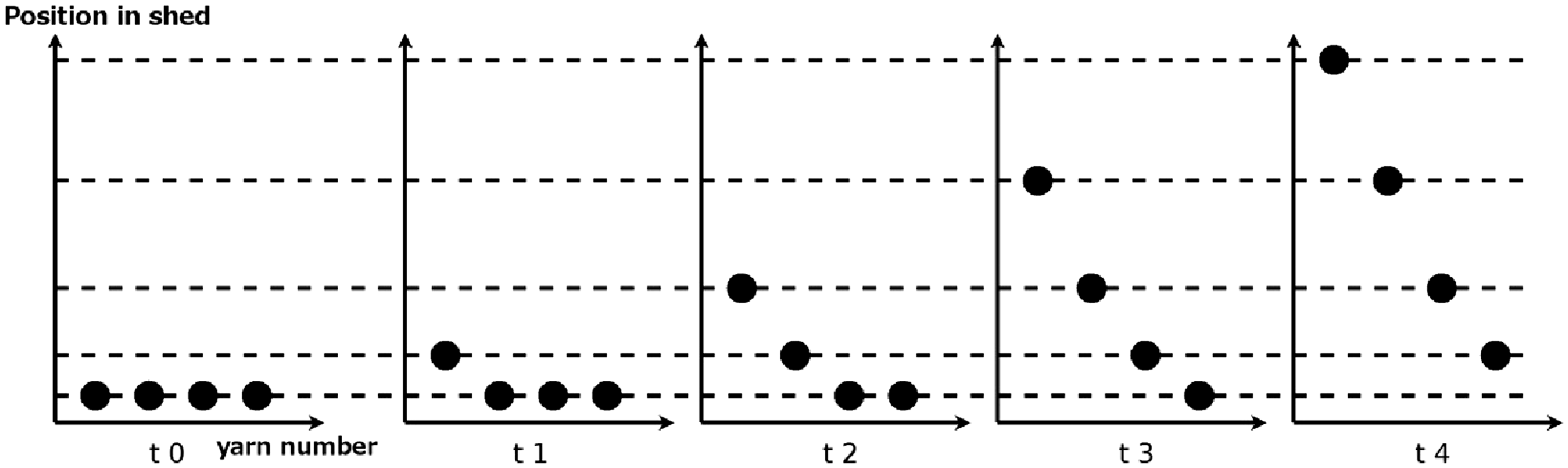
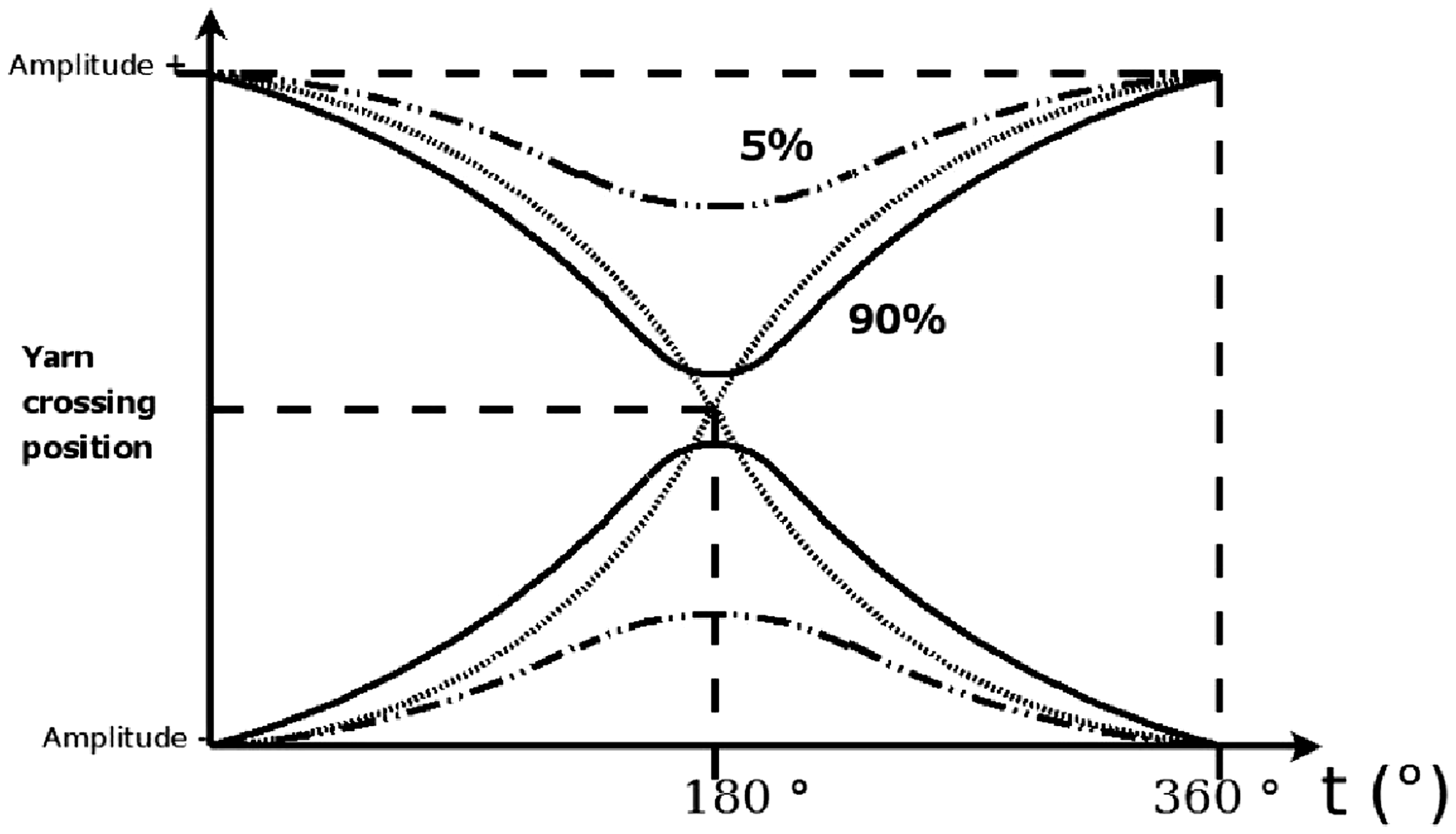
Figures 5 and 6 illustrate shed profile and close shed profile principles, with the curves which will be used for the DOE. In Figure 5, the diagram shows yarn vertical position in the shed according to shedding time cycle. The first profile is the quite-sinusoidal number 2, which is compared to the more complex number 6: once yarns have stayed static for a while, they will get a strong acceleration so they can have a high crossing speed. With close shed profile in Figure 4, the distance (in %) between yarn open shed position and the centre of the shed may be small (like the 10% level we use), or may bring the yarn very close to the middle of the shed (90%).
Shed profile diagram chosen for experiments. Close shed profiles set for experiments.
The effect of a geometry offset may be seen in Figure 7: Figure 7(a) is a simple and basic flat geometry. Even if any can be possible, the most fanciful might not be so useful. The regular offset added in Figure 7(b) brings an open shed density decrease, thanks to shed layers’ dissociation. For both levels, the structure of geometry and offset stays the same, but spacing between the crenelated sub-layers is set small (5 mm) or high (10 mm).
Effect of geometry offset: (a) flat basic geometry; (b) flat geometry with regular offset.
Yarns and weave pattern
Warp is composed of 512 polyester 1700 dtex multi-filament yarns. They are arranged according to the Jacquard harness drawing-in, into 32 columns of 16 yarns. Reeding is 16 yarns per reed dent, which allows weaving HDMW fabrics containing up to 16 warp layers. Warp yarns are condensed into a 3 cm2 fabric section, hence a high density of 16 ktex/cm. Figure 8 depicts a eight-pick warp cross-section woven fabric developed for the design of experiments and warp yarns crossing for each shedding. This weave pattern was designed for a constant amount of interactions which is eight for each step and reed dent. Its use over 100 picks, with a take-up of 1 mm per pick forms 100 mm of fabric per experiment.
Warp cross-section of the woven fabric used for experiments.
The 16 settings of the DOE have been repeated four times. For each repeat, drawing of experiments was randomised. In this experimental design, we have considered errors detected by the UNIVAL detection system which consists in detecting over or under-loads, or yarns out of their set position area.
First results and discussions
Raw results
DOE results—four repetitions.
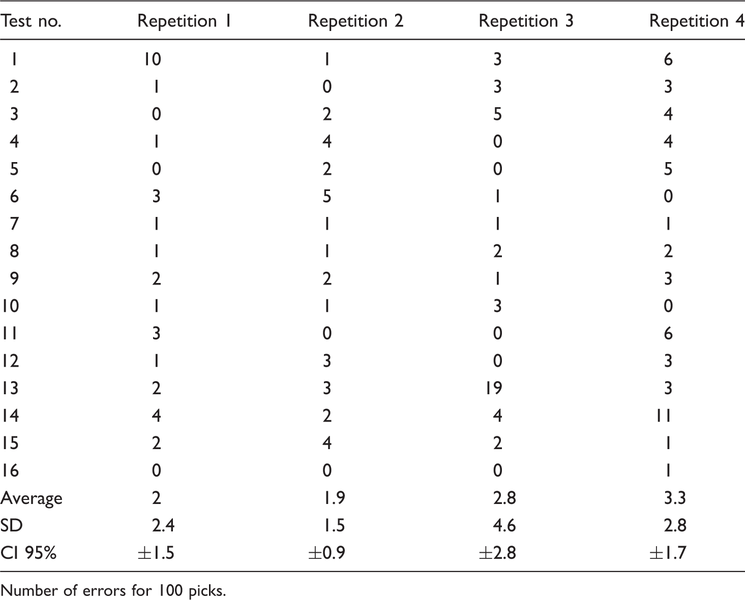
Number of errors for 100 picks.
Coefficients analysis
Results in Table 3 are also used to calculate parameters effects coefficients, for each repetition, and finally for total, as it may be seen in Figure 10. Only repetition 3 has significant coefficients with close shed profile and offset geometry coefficients having a value under − 1 and repetition 1 close shed profile is near − 1. Repetition 3 shed profile and phase difference coefficients are also close to 1. Other coefficients, especially with repetition 2, are very low, which may be linked to the low deviation. These previous results are echoed in Figure 9 where relative weights are calculated from parameters variances. It seems difficult to rely on repetitions number 4 and especially number 2 as they have a quasi-non-existent weight. Phase difference and shed profile parameters are globally also not much present compared to close shed profile and offset parameters.
Relative weight of DOE parameter, calculated from parameters variance. Comparison of parameters repetitions values.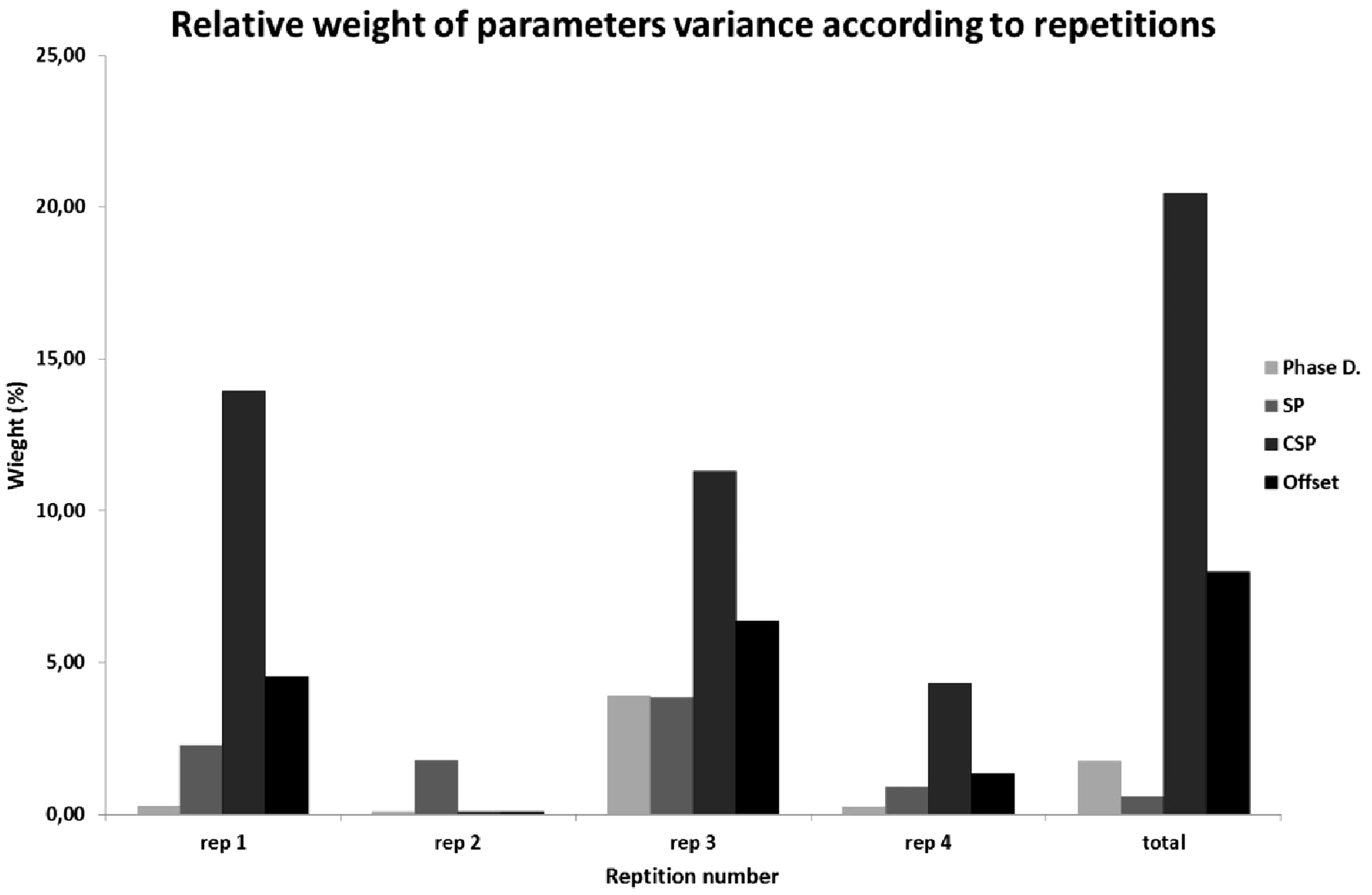

According to Figure 10, geometry offset and close shed profile parameters have corroborating repetitions coefficients. These negative coefficients seem to indicate that a high level of close shed profile and a high geometry offset tend to reduce error occurrences. It may be explained by density reduction and presence of a relative movement between theoretically static yarns and shedding yarns at motion start. Results for phase difference and shed profile might suggest that high values of these parameters are increasing the number of errors. An explanation for shed profile could be a too high speed which increases fibrillation and therefore position errors. It is difficult to rely on the parameters’ results for several reasons. Some of the coefficients are not significant enough. The origin of the trend comes from repetition 3, as the coefficients of all repetitions are globally in opposition for these two parameters.
Interactions analysis
Figure 11 gives the DOE parameters interactions. A first look shows significant coefficients over the absolute value 1, for ×12 and ×13 interactions of repetition 3 and ×23 interaction of repetition 4. The choice was to take only in account interactions having a homogeneous trend like ×12 and ×34, or a global trend like ×23 where a majority of repetitions have a negative coefficient. Interaction ×13 will not be taken into account because of the opposition repetition 1 coefficient which is higher than repetition 2 and 4 coefficients. The three previously selected interactions are described with the use of the total coefficient value in Figures 12 to 14.
Comparison of parameters interactions repetitions values. ×1: phase difference, ×2: shed profile, ×3: close shed profile, ×4: geometry offset. Interaction a12: phase difference and shed profile. Interaction a23: shed profile and close shed profile. Interaction a34: close shed profile and geometry offset.


We may first notice that the most crucial interaction is ×12: interactions ×23 and ×34 give configurations which reduce an already small amount of errors. In comparison, interaction ×12 enables to half errors from 12 or 14 to 6 or 7. In Figure 12, the right combination seems to be a high phase difference with a small shed profile number, or its opposite combination. In Figure 13, a high value of close shed profile tends to reduce detected errors, whatever the shed profile set. Finally, weaving seems to be improved with a high geometry offset combined to a high close shed profile value (Figure 14). Interactions results are in accordance with single parameters coefficients: errors might be decreased with a high close shed profile and geometry offset and a low value of phase difference and shed profile. Mc Hugh [13] found that the combination a high shed profile (No. 6) and a high close shed profile (about 87%) clearly reduced carbon fibrillation. Our results about close shed profile are obviously in accordance, but the effect of shed profile is not so clear and needs further studies.
The notable deviation or even sometimes opposition between repetition coefficients in a single parameter makes parameters effects hard to clarify and explain and concentrates our reflection on a bias in our DOE. Indeed, these results are in global contradiction with a previous study [16]. Conditions were quite similar with close parameters levels DOE inputs, but with no repetitions of experiments. Even if the use of repetitions gives credit to this present study, the variation between global results shows that long-term errors collection is required. This observation is reinforced with the general study of variance in Figure 9: any of the parameters’ weights does not exceed 21%, meaning that residual represents 70 to 98% of the weight. Such a strong background noise may be due to a parameter not or incorrectly taken into account, which constitutes a bias. According to Figure 15, we can note a global increase of the average number of errors. This observation needs to be cautious because of high deviation. Number of errors seems to increase in time, as the design repetition number corresponds to its realisation order. We may think that such a bias may come from the fibrillation phenomenon as in Figure 1(b) which is a photo of warp yarns during these experiments.
Evolution of errors average value according to the repetition.
New methodology, results and discussions
Methodology validation
In order to overcome this difficulty and eliminate bias, a second DOE whose results are shown in Figure 16, was carried out. It is taking in account pick number in a way that the evolution of errors can be described according to time. Errors are also counted from a new and perfectly clear shed to a high number of picks. Because of the long weaving time needed for each experiment, only two parameters with two levels where chosen, which makes four experiments; the two UNIVAL parameters were shed profile and close shed profile. The curves in Figure 16 show the cumulative errors for each parameter configuration according pick number. Straight lines were added over curves to describe experiments global trend. It may be first noticed that curves’ evolutions are quite linear and very different to one other; the semblance of linearity sets up between 500 and 1500 picks, which proves that 100-pick experiments are too small. According to Table 4, it is also confirmed that our bias was fibrillation and it needs to be examined in the long-term: the variance analysis indicates higher relative weights than previously, especially for close shed profile which is clearly the major parameter with an 80% weight. Indeed, this new methodology is more relevant as residual has fallen to 2.2% which is acceptable and ANOVA P-values are far smaller than 0.05.
Cumulative errors according to pick number of DOE having shed profile and close shed profile as parameters. ANOVA for second DOE, with two levels shed profile and close shed profile.

Enhanced results
In Figure 16, the two highest trends are given by experiments 1 and 2, where close shed profile has a low level. In opposition, the high level close shed profile clearly reduces the increase of errors in time, which confirms the results found about this parameter in the previous DOE. It was found before, even if it was difficult to make a clear interpretation, that a high shed profile had not had a positive effect for high-density weaving. This trend is strengthened by high shed profile curves of experiments 2 and 3 in Figure 16, where the number of errors is medium to important. At last, let us note that a very interesting configuration appears: a high close shed profile combined to a low shed profile generates the lowest evolution.
Conclusion
Fibrillation has a fundamental effect on HDMW fabrics: it needs to be avoided or at least reduced. It appears that fibrillation had not been sufficiently taken in account in our first DOE with such a high density, as it increased all along experiments, so that previous experiments yarn damages would have an influence on the next coming. DOE inputs have also been reduced in our second DOE in order to precisely focus on few parameters. Further researches need to be carried out about the potential of the UNIVAL technology, as this study is the first global approach about such revolutionary shedding parameters. The long-term study of fibrillation needs to be spread to the other parameters. Several intermediate results have been found, involving close shed profile and geometry offset parameters which, with high level value, can reduce the number of shedding errors. The two other parameters have a less significant effect because of deviation and despite repetition of experiments, even if a high shed profile speed tends to increase shed damages and errors. It has been finally found for the first time that while waiting for other parameters’ results, the combination of high close shed profile and low level shed profile could drastically reduce fibrillation, compared to the other configurations.
Footnotes
Declaration of Conflicting Interests
The author(s) declared no potential conflicts of interest with respect to the research, authorship, and/or publication of this article.
Funding
The author(s) disclosed receipt of the following financial support for the research, authorship, and/or publication of this article.