
Abstract
A growing interest in biocomposites leads to the extension of commonly used three-dimensional braiding processes for composite preforming to cellulose-based fibres. A rayon fibre (Cordenka™) is processed on an Institut für Textiltechnik 3D rotary braiding machine, generally used for the processing of stronger and stiffer glass and carbon fibres. A rectangular profile was produced from 32 yarns and the braiding angle of the yarn was analysed. Analysis of the fibre tensile properties during the different processing steps revealed only a minor reduction in fibre strain. The fibre strength and Young’s modulus were unaffected by the braiding process showing that 3D rotary braiding can be extended to biobased fibres without any required changes.
Introduction
Two-dimensional (2D)-layered fibre structures are critical components of modern day advanced composite materials. 2D textile technologies are now firmly established in the aircraft, maritime, automotive and construction industries [1]. However, the poor drapeability of some 2D textiles often requires that complex three-dimensional (3D) shapes are formed by joining separate 2D composite laminates through adhesive or mechanical fastening [2].
An alternative technology for producing 3D-shaped composites is through the use of 3D textiles. According to Gries et al. [3], ‘a textile is defined as a 3D textile if its yarn architecture extends in three directions, regardless of whether it is made in a one-step process or a multiple-step process’. One-step processes are based on technologies such as 3D braiding, 3D weaving or 3D knitting whereas multiple-step processes generally involve stitching together or over-braiding of 2D textiles. The types of fibres used in the production of 3D textiles are typically carbon, aramid and, to a lesser extent, glass fibre [3,4].
The one-step 3D braiding process was the first process to be used in the fabrication of advanced composite materials with a 3D fibre architecture [5]. The reinforcement of composites with 3D braided textiles results in higher delamination resistance, improved impact resistance and lower notch sensitivity compared with those based on conventional 2D textile reinforcements [5,6]. In general, composites based on 3D textiles exhibit improved through-thickness properties compared to their 2D counterparts [7].
Cellulose fibres (natural or man-made) have lower density than glass fibres or mineral fillers. Cellulose fibres are also characterised by high-specific tensile strength and stiffness, making them a lightweight, sustainable alternative reinforcement to glass fibres [8]. Cellulose fibres are also advantageous during textile processing as they are less hazardous to handle and cause little abrasion to the processing equipment [9]. Hence, the use of cellulosic fibre as reinforcement is growing in interest within the composite industry. Composite materials that are based on cellulosic fibres are generally referred to as biocomposites since they are partially or fully derived from biomass [9].
In contrast to natural cellulose fibres, man-made cellulose fibres are industrially processed fibres, made from purified, dissolved and regenerated natural cellulose sources. The regeneration process also transforms the native cellulose structure (cellulose I) into a more stable form (cellulose II) that in general has lower mechanical properties than cellulose I. Viscose rayon and Lyocell fibre are the two main types of man-made cellulose fibres of industrial importance [10]. In contrast to natural fibres, the processing of man-made cellulose fibres ensures that fibre properties are relatively consistent. For example, natural flax fibre exhibits higher values of strength and stiffness than man-made cellulose fibres. However, the high variability of mechanical properties of natural flax fibre translates to average properties in the same range as rayon tire cord and Lyocell fibres [11]. Natural and regenerated cellulose fibres have been processed as continuous fibre yarns into 2D composite preforms using pultrusion and tubular braiding techniques [12]. However, there have been very few studies on the processing of 3D textiles based on natural or regenerated cellulose fibre.
The present work will report for the first time the production of 3D textiles from a man-made regenerated cellulose fibre (Cordenka™ rayon). It is shown that it is possible to process a regenerated cellulose fibre into a 3D-braided preform using braiding equipment developed for glass and carbon fibres. The study reports on the properties of the fibre before and after processing to investigate the occurrence of fibre damage during processing. The present study is of considerable interest to the biocomposites community that is focussed on the use of cellulosic fibres as next generation eco-materials in composites.
Experimental procedures
Materials
A Cordenka™ yarn made entirely from cellulose II (Cordenka, Obernburg, Germany) with 10,000 single filaments per yarn with a fibre fineness of 1440 dtex was used for the braiding process. An elementary fibre of the Cordenka™ yarn has a diameter of 12 µm, tensile strength of 830 MPa, Young’s modulus of 20 GPa and elongation at break of 13% [13].
3D braiding process
A recent development in 3D braiding technology is 3D rotary braiding in which yarn carriers are positioned on rotating horn gears, thereby allowing complex braiding paths [5,6]. The Institut für Textiltechnik (ITA) 3D rotary braiding technology was used to produce 3D preforms. The principle of the 3D rotary braiding technique is illustrated in Figure 1. Shifted via horn gears, the bobbin carriers can be directed to any position on the machine plate guided by tracks and switches. Thus, a huge range of different yarn architectures is possible. The 3D rotary braiding machine type CAB-9-32-220 used in this study was developed by ITA and Herzog (August Herzog Maschinenfabrik GmbH & Co. KG, Oldenburg, Germany).
Principle of 3D rotary braiding and 3D rotary braiding machine housed at ITA.
The architecture of the braid was designed to have rectangular cross-section (i.e. a preform with a rectangular cuboid shape) using Herzog software (CAB-0.20-04, August Herzog Maschinenfabrik GmbH & Co. KG, Oldenburg, Germany) to control the braiding machine. Thirty-two horn gears supplied with 68 bobbins were necessary to produce the desired braid. The four different braiding steps, direction of rotation of the horn gears and position of the bobbins in each step are illustrated in Figure 2. Approximately 80 m of the yarn was loaded onto each bobbin using a Herzog 280/PN rewinding machine applying a rewinding speed of 25 m/min.
Schematic representation of the programmed braiding path to manufacture a rectangular cuboid preform based on the Cordenka yarn. The crosses and circles represent the horn gears and attached bobbins, respectively. The arrows indicate the direction of rotation of each horn gear during each step.
Fibre and preform characterisation
Thirty single fibres were taken from each of the yarn bobbins and final braided preform to investigate the influence of spooling and braiding on the fibre properties. The fibres were conditioned at 20℃ and 65% RH prior to testing. The fibres were tensile tested according to DIN EN ISO 5079 using a Fafegraph M (Textechno, Herbert Stein GmbH & Co. KG, Mönchengladbach, Germany). The fibres were clamped using pneumatic clamps with a clamping pressure of 0.4 MPa and testing length of 20 mm. The tensile test rate was 20 mm/min and the load was recorded using a 0.1 N load cell. A preload of 0.0001 N was applied just prior to testing using a 100 mg weight to avoid fibre crimping.
Four images were taken of the surface of eight different samples using an Olympus SZH10 stereo microscope (Olympus Corporation, Tokyo, Japan) with an attached Zeiss AxioCam camera (Carl Zeiss AG, Jena, Germany) in order to measure the braiding angle. The braiding angle was measured using computer image analysis (ImageJ, National Institutes of Health, Bethesda, Maryland, USA). One hundred measurements of the braiding angle were taken along the longitudinal axis of each sample. Each measurement was performed three times to minimise the effect of a non-automated measurement technique, resulting in a total of 300 measurements.
A 5 mm long section was cut from the braid to observe changes in the microstructure after processing. The sections were covered with a thin layer of in Epofix cold-setting embedding resin (Electron Microscopy Sciences, Hatfield, PA, USA) to freeze the braid structure. The sections were then mounted along their longitudinal axis in Epofix resin and polished metallurgically according to ASTM E3 – 01 (2007) to a grain size of 1 µm. A Leica DR IRM microscope (Leica, Wetzlar, Germany) was used for optical analysis of the braids. Reflected light micrographs of the cross-section were taken using a NIKON Digital Sight DS-Fi1 camera (Nikon Imaging Japan Inc., Tokyo, Japan) with the software NIKON NIS Elements F 3.2 (Nikon Imaging Japan Inc., Tokyo, Japan).
The average values of the determined fibre properties were statistically compared using a Wilcoxon signed-rank test. The average values of the measured braiding angle were compared using a one-way ANOVA analysis. All statistical analyses were carried out using the software ‘R’ (Bell Laboratories, Murray Hill, NJ, USA).
Results and discussion
A 3D braid consisting of 68 yarns, and with a thickness and width of ∼4 and 10 mm, respectively, was successfully fabricated (Figure 3). The final shape of the braid was of a rectangular cuboid of regular consistency, showing no obvious defects. However, some minor separation of single fibres from the yarns could be observed. An exemplary close-up of the braid structure used to determine the braiding angle is also provided in Figure 3.
Photograph of the top and lateral view of the final rectangular cuboid 3D braided structure. Arrows indicate the separation of single fibre from the braid. A close-up of the braid structure is also shown.
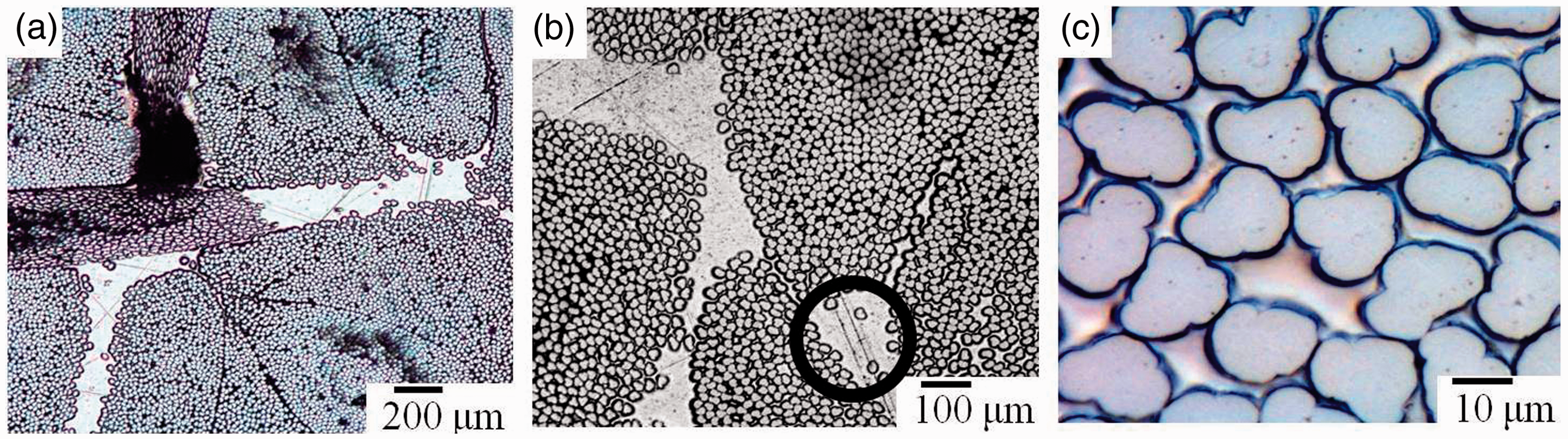
The braiding angles were found to range from 17.17 to 23.81° (Figure 4). However, there was no significant statistical difference in the braiding angle due to the large standard deviation. The variations in braiding angle are presumed to be due to splicing that occurs between the Cordenka™ yarns during braiding. During splicing, it is thought that individual fibres are able to separate from the yarn since no-twist yarns were used. The moving yarn carriers with the attached horn gears will cause an interweaving of individual fibres just prior to the actual braiding point, which may influence the final braid angle. It was observed that not all adjacent yarns in the final braided structure neighboured each other closely, leading to a variation in the braiding angle (Figure 5(a)). Additionally, the separation of single fibres from a yarn could be identified (Figure 5(b)).
Average values of the braiding angle for eight different samples. Error bars indicate one standard deviation. Reflected light micrographs of the cross-section of the braid showing (a) several yarns, (b) a yarn crossover point with a single fibre that was separated from its yarn (circled) and (c) single fibres within a yarn.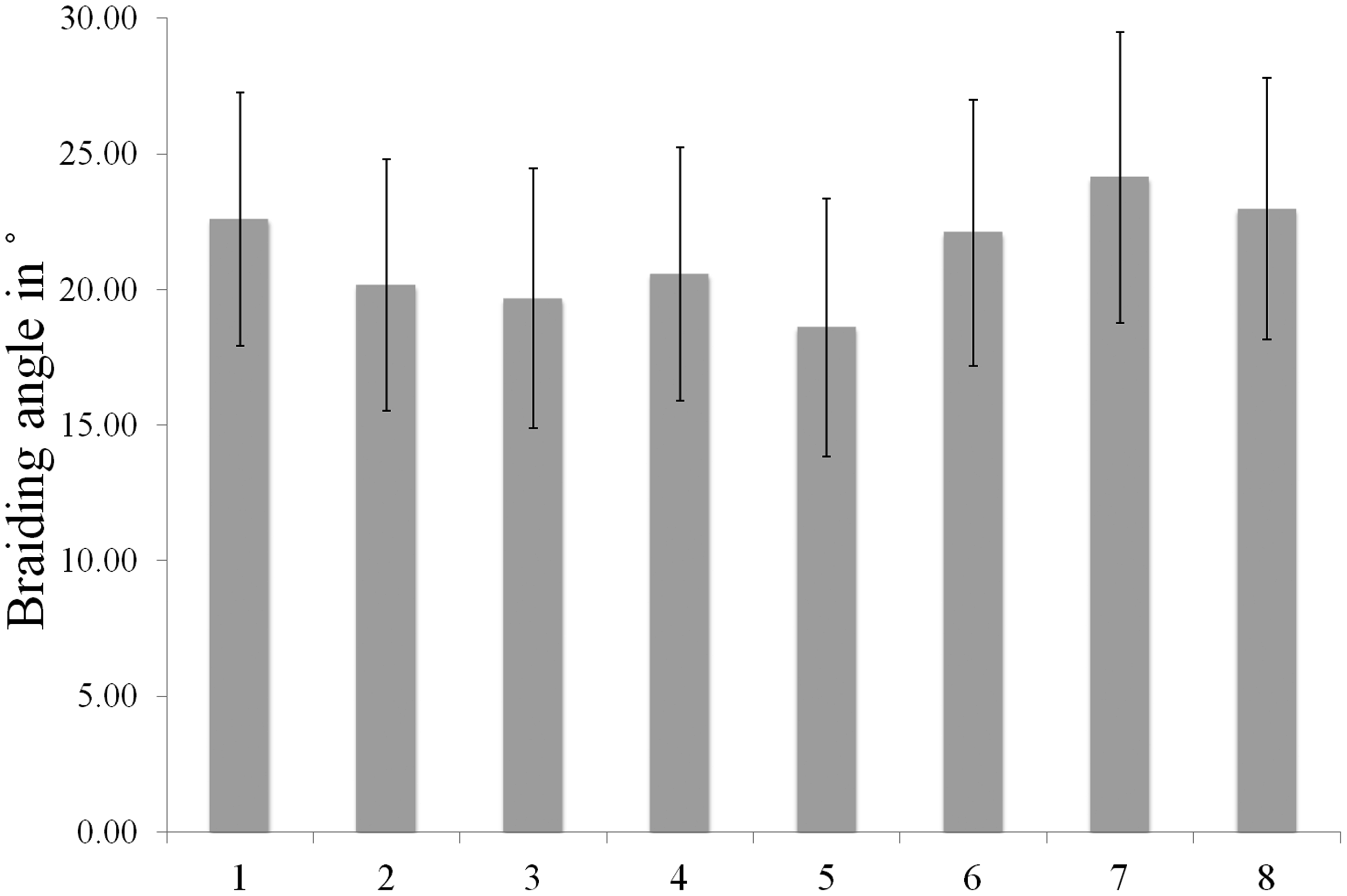
The final braid angle is critically important since it determines the mechanical properties of the resulting composite [14].
The ultimate tensile strength (427.13 ± 62.77 MPa) and strain to failure (10.60 ± 2.13 %) of the original fibre (Figure 6) were lower than the expected values as reported by the supplier (830 MPa, 13%) [13]. However, the measurement of the strength of single fibres is experimentally difficult such that the methodology is often a contributing factor to discrepancies between literature and measured values [15].
The average (n = 30) ultimate tensile strength and strain to failure of single fibres as a function of processing. Measurements of the original yarn are compared to effects of rewinding to the bobbin and braiding. Error bars indicate one standard deviation.
No statistically significant difference in the ultimate tensile strength was measured following each of the processing steps (441.18 ± 52.82 MPa and 455.49 ± 54.13 MPa, Figure 6), demonstrating that the 3D rotary braiding process did not reduce the strength of the rayon fibres. However, there was a small, yet statistically significant, reduction in the strain to failure from 10.06 ± 2.13% for the as-received fibres to 9.41 ± 1.1% and 9.61 ± 1.4% after rewinding and braiding, respectively (Figure 6). No statistically significant difference was found between the strain to failure of the rewound and braided fibres.
Interestingly, in contrast to carbon [16] and glass fibres when used in 2D braiding processes [17] or glass fibres used during 3D weaving [18], the braiding process itself does not reduce the fibre strength in spite of single fibres being separated from the yarns. It is possible that the high strain to failure of the rayon fibres helps to prevent fibre damage that occurs in more brittle carbon and glass fibres.
Conclusions
It could be shown that the ITA-Herzog 3D rotary braiding process can be successfully applied to man-made cellulose fibres without causing significant damage to the fibres in spite of the process having been developed and optimised for higher strength glass and carbon fibres. The braiding process is envisaged to be a potentially important process in the fabrication of high performance, 3D-shaped biocomposites. The polar surface of the cellulose fibres leads to the separation of single fibres from the yarns during the braiding process, resulting in a high variation of the braiding angle.
Footnotes
Acknowledgements
The authors are grateful to Rudolf Einsiedel and David Wunderlich of Cordenka™ (Obernburg, Germany) for kindly providing the rayon fibre used in this study. The authors also thank the technical staff at the Institut für Textiltechnik (ITA) of the RWTH Aachen for technical assistance with the braiding process.
Declaration of Conflicting Interests
The author(s) declared no potential conflicts of interest with respect to the research, authorship, and/or publication of this article.
Funding
The author(s) disclosed receipt of the following financial support for the research, authorship, and/or publication of this article: This study was financially supported by the New Zealand Ministry of Business, Innovation & Employment.