
Abstract
The aim of this study was to understand the warp–weft directional bending properties of the developed two-dimensional multistitched multilayer E-glass/polyester woven nano composites. The warp–weft directional specific bending strengths and modulus of unstitched/nano composite structures were higher than those of the unstitched structures. Contrarily, the warp–weft directional specific bending strengths and modulus of unstitched structure were higher than those of the machine stitched and machine stitched/nano structures due to stitching caused filament breakages. When the stitching direction increased, the warp–weft directional bending strengths and modulus of the structures decreased. The warp–weft directional specific damaged areas of unstitched structure were higher than those of the multistitched and multistitched/nano structures. The addition of nano silica to the stitched structures improved their damage resistance slightly. It was generally found that when the number of stitching directions and stitching density in structures increased, the damaged areas of structures decreased. The failure of warp–weft directional multistitched and multistitched/nano woven E-glass/polyester composite structures was matrix breakages, partial and complete filaments, and yarn (tow) breakages in their surfaces. They had a local delamination in their cross-sections and the delamination did not propagate to the large areas due to multiple stitching. The failure was confined at a narrow area due to multistitching and resulted in the catastrophic fiber breakages. This was considered that the damage tolerance performance of the multistitched structures was enhanced due to stitching, in particular, at four directional stitching.
Keywords
Introduction
Textile structural composites have been used in various industrial, ballistic, and medical areas due to their high stiffness-to-weight ratio, delamination free, and damage tolerance properties [1–4]. Textile preforms are made by weaving, braiding, knitting, stitching, and nonwoven techniques and they can be chosen generally according to end-use requirements [5].
Stitching improved the tensile and flexural properties of the two-dimensional (2D) woven composite through the distribution of the stress among the layers [6]. The delamination crack propagation in 2D stitched woven composites was suppressed by using the high linear density stitching yarns [7]. It was reported that adding a few percent stitching yarn to the out-of-plane direction of the composite improved the thickness direction tensile modulus of the structure [8]. For instance, the effectiveness of stitching to suppress impact-induced delamination can be achieved once the stitch yarn volume fraction is 0.4% [9]. The stitch hole size determined the in-plane and the out-of- plane properties and it depended on the stitching yarn diameter, needle size, and yarn tension during stitching process [10]. It was shown that higher stitch density was better at impeding delamination growth by arresting cracks at closer interval and suppressing crack propagation [11]. The uniform distribution of stitching yarns in the woven composite resulted in better in-plane tensile and impact strengths [12]. Contrarily, it was reported that the three-point flexural strength of two directional stitched E-glass/vinyl ester composite structure was reduced by stitching and stitched induced stress concentration sites [13, 14].
A fiber distortion model was developed to describe the spatial distribution of in-plane fiber misalignment angle and inhomogeneous fiber volume fraction induced by stitching [15]. It was claimed that stiffness properties of the stitched woven composite were not significantly affected by the stitching yarn [16]. The stitching in the through-the-thickness direction increased impact damage tolerance especially at low temperatures. A strong correlation of energy absorption with respect to stitching yarn fracture works in relation to its fiber volume fraction was found [17]. In addition, it was reported that the 2D woven stitched composite showed a significant increase in energy absorption capability under repeated impact [18]. Stitching improved the damage resistance properties of woven composite structure under blast load and ballistic impact load [19].
The damage initiation force for three-dimensional (3D) noninterlaced stitched composite was lower than in 2D unstitched woven composite due to weak resin-rich regions around the stitch loops [20–22]. Tensile studies performed on 3D orthogonal woven composites revealed that weaving damage was responsible for a significant reduction in tensile strength [23]. It was demonstrated that the mechanical properties such as the tensile and compression stiffness of 3D noncrimped fabric were not degraded by the stitching parameters. But, the tensile and compression strength and the tensile fatigue behavior of 3D noncrimped fabric were reduced as a result of pronounced localized fiber undulations due to stitching [24]. It was found that the in-plane shear strength and modulus of the multiaxis 3D woven carbon composite were higher than that of the 3D orthogonal woven carbon composite. However, the bending strength, bending modulus, and interlaminar shear strength of the multiaxis 3D woven carbon composite were slightly lower than that of the 3D orthogonal woven carbon composite. This was because of the orientations of the bias yarns on both surfaces of the multiaxis 3D woven structure [25, 26].
The 2D woven nano clay composite showed not only better stiffness but also an increase of impact resistance and fracture toughness [27]. For instance, the addition of 3 wt. % nano clay on the E-glass/vinyl ester composite increased its tensile properties [28]. On the other hand, the tensile strength and modulus of 2D noncrimp biaxial E-glass/epoxy composites remain unchanged by the addition of 6 wt. % clay contents [29]. The 2D woven carbon/epoxy amine coated single wall carbon nano tube (CNT) composite showed improvement in the tensile strength and resistance to tensile–tensile fatigue damage [30]. It was claimed that the interface properties of 2D woven E-glass/vinyl ester composites were enhanced when the coated nanotubes were used [31]. It was also found that nanotubes with amine functional groups have better tensile strength, as compared to those with untreated CNTs [32]. The modulus increased by adding silicon carbide (SiC) nanoparticles regardless of the dispersion quality, whereas strength was highly sensitive to dispersion quality and increased with the addition of the coupling agent and dispersant. Hence a well-dispersed SiC was required to improve the nanocomposite quality [33]. In addition, the tensile strength of the E-glass/unsaturated isophthalic polyester composite decreased by the increasing of the SiC particle. The reasons were that the weak bonding at the interface between the SiC particles and the matrix, and the particle geometry which resulted in stress concentration in the polyester matrix [34]. As seen in the literature, the studies were mainly concentrated on the stitched structures having stitching at their principal directions. But, no research was carried out on the multistitched structures having stitching at their ±bias as well as principal directions and nano added multistitched structures. In this way, it was expected that bending properties of the E-glass/polyester composite structures could be enhanced by multistitching and nano added multistitching. The developed multistitched and multistitched/nano composite structures could be used in aerospace applications as structural parts. Therefore, the objective of this study was to develop 2D multistitched, multistitched/nano E-glass/polyester structures to experimentally understand the warp–weft directional bending properties of those structures.
Materials and methods
2D unstitched and multistitched multilayer woven E-glass/polyester preform and composite
Specifications of high modulus fiber, matrix, nano, and E-glass woven fabric used for making composite.
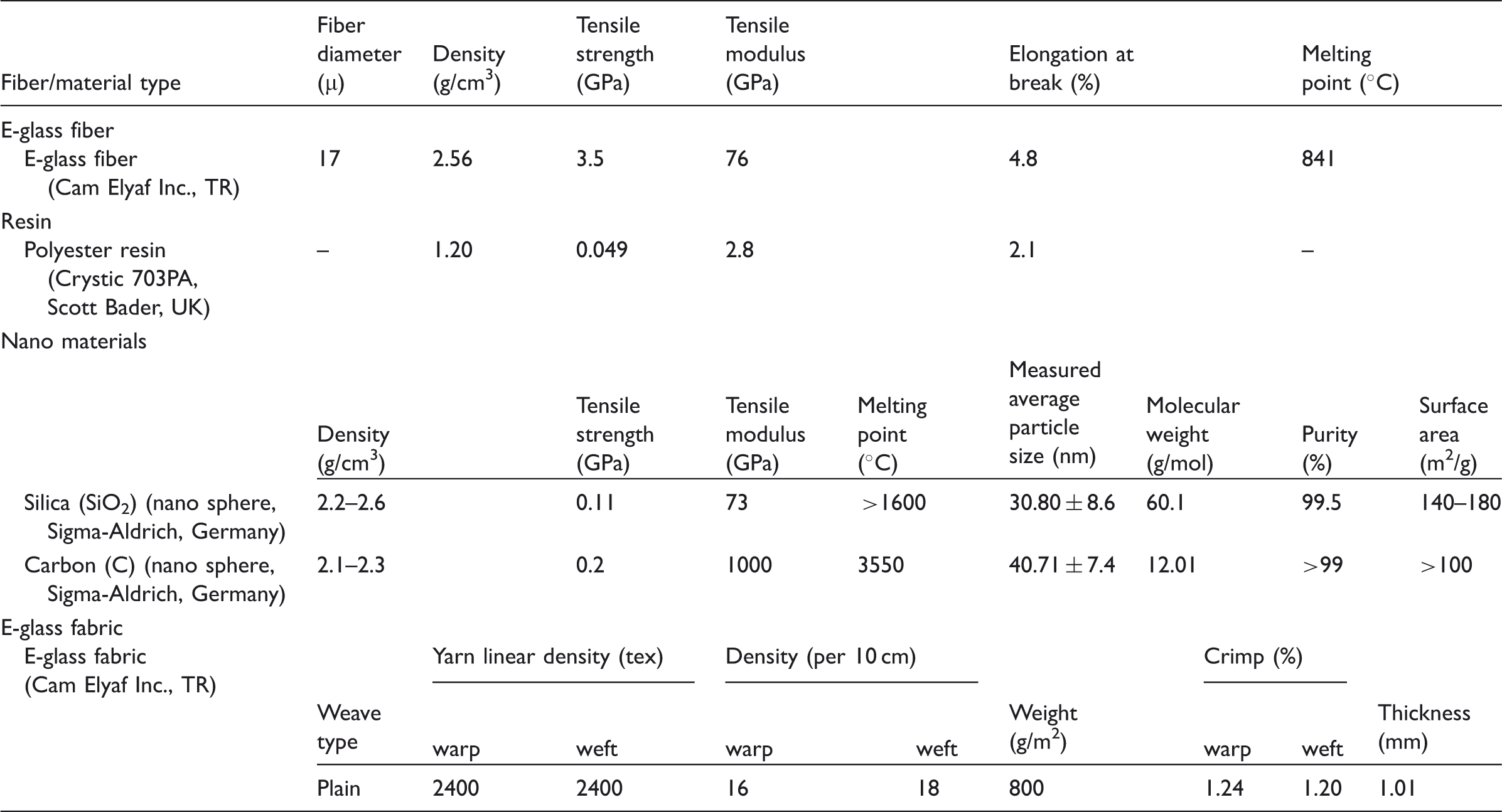
Crimp measurement was performed using a Tautex digital instrument (James H. Heal Co., UK) based on ISO 7211-3. The fabric thickness measurement was performed using an EV07 digital device (Elastocon, Sweden). The fabric weight measurement was performed based on ISO 6348 using an Ohaus Adventurer™ Pro AV812 (Ohaus Corp., USA) digital balance. In addition, the E-glass fabrics were examined by an optical microscope (Olympus SZ61, Japan equipped with digital image analysis software- Bs200DOC, Turkey).
Six types of E-glass preform structures were mainly developed: unstitched (T1a–T1c), unstitched/nano (T2a–T2d), hand stitched (T3a–T3i), machine stitched (T4a–T4l), machine stitched/nano and hand stitched/nano (T5a–T5b). Figure 1 shows the schematic top view of one directional stitching (a1), two directional stitching (a2), four directional stitching (a3), schematic view of the hand stitching at 0–90°, ±45° directions (b1, b2), and schematic view of machine stitching at 0–90°, ±45° directions (b3, b4). The developed unstitched preforms included a layered fabric [0°/90°]4 (T1a) and oriented layered fabrics as [0/90/ ± 45/ ± 45/0/90] (T1b) and [ ± 45/0/90/0/90/ ± 45] (T1c). The developed machine and hand stitched preforms were divided into three subgroups. The first was a layered fabric [0°/90°]4 one-directionally stitched in the warp (0°) direction. The second was a layered fabric [0°/90°]4 two-directionally stitched in the warp (0°) and weft (90°) directions. The third was a layered fabric [0°/90°]4 four-directionally stitched in the warp (0°), weft (90°), and bias directions. In machine stitching, lock stitching was used and the stitching density was varied at 2 step/cm (light stitching) and 6 step/cm (dense stitching). The distance between the adjacent stitching lines was 1 cm. The stitching yarns were also varied using fully nylon 6.6 (bobbin and needle yarn) and Kevlar® 129 as the bobbin stitching yarn and nylon 6.6 as the needle stitching yarn. The stitching machine was produced by Brother Industries Ltd, DB2-B736-3TR, Japan. In hand stitching, the stitching density was 1 step/cm. The distance between the adjacent stitching lines was 1 cm. The stitching yarns used were Kevlar® 129, E-glass, and carbon. The properties of the stitching yarns are presented in Table 2.
Schematic views of stitching directions of E-glass preforms. (a1) top view of one direction; (a2) top view of two direction; (a3) top view of four direction stitching schematic; (b1, b2) schematic cross-sectional view of hand stitching at 0° and 90°, and at ±45°; (b3, b4) schematic cross-sectional view of machine stitching at 0° and 90°, and at ±45°. Specifications of stitching yarns. K = 1000 filament at the TOW.

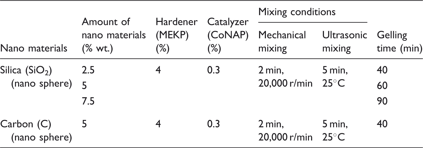
Two-dimensional unstitched and multistitched multilayer woven E-glass/polyester preforms were consolidated to make composites. Vacuum-assisted resin transfer molding (VARTM) was used to make composite which is an easy and cost-effective technique to consolidate preforms. Dicyclopentadiene based unsaturated polyester resin (Crystic 703PA, Scott Bader, UK) was used. Methyl ethyl ketone peroxide (MEKP) was used as hardener, 2% by weight of resin to produce neat E-glass/polyester composites. The polyester resin and hardener were mixed homogenously and applied to the preforms under vacuum at 20℃. However, catalyst (Cobalt Naftalat-CoNAP) was also used to produce nano composite structures. Amounts of MEKP and CoNAP by weight of resin and mixing conditions are presented in Table 3. Nano materials were mixed first by a mechanical stirrer (IKA-T25 Digital Ultra Turrax, IKA® Werke GmbH & Co. KG) in which mixing was gradually carried out starting from 3000 to 20,000 r/min, stay 2 min, then from 20,000 to 3000 r/min. Later on, mixing was continued in ultrasonic bath, 5 min at 25℃, to get homogeneous distribution of nano particles in polyester resin. After that, matrix was vacuumed to get rid of the air bubble, and finally hardener and catalyst were added. This matrix was applied to the preforms under vacuum at 20℃. Figure 2 shows some of the 2D unstitched, multistitched woven E-glass/polyester nano composites. We did not increase the amount of nano material in the composite structure due to VARTM method. Thus, the development of new consolidation method for nano material is required. In addition, it was suspected that the nano material was agglomerated during mixing and consolidation. These are the future research objectives of this study.
Two-dimensional woven E-glass/polyester composite structures. (a) Unstitched structure(T1a); (b) unstitched/nano structure (T2b); (c) hand stitched with Kevlar® 129 and carbon structures (T3c, T3i), respectively; (d) machine stitched with Kevlar®129 and nylon 6.6 structures (T4l, T4f), respectively; (e) machine stitched/nano structure (T5a). Mixing conditions of nano materials in polyester resin for VARTM.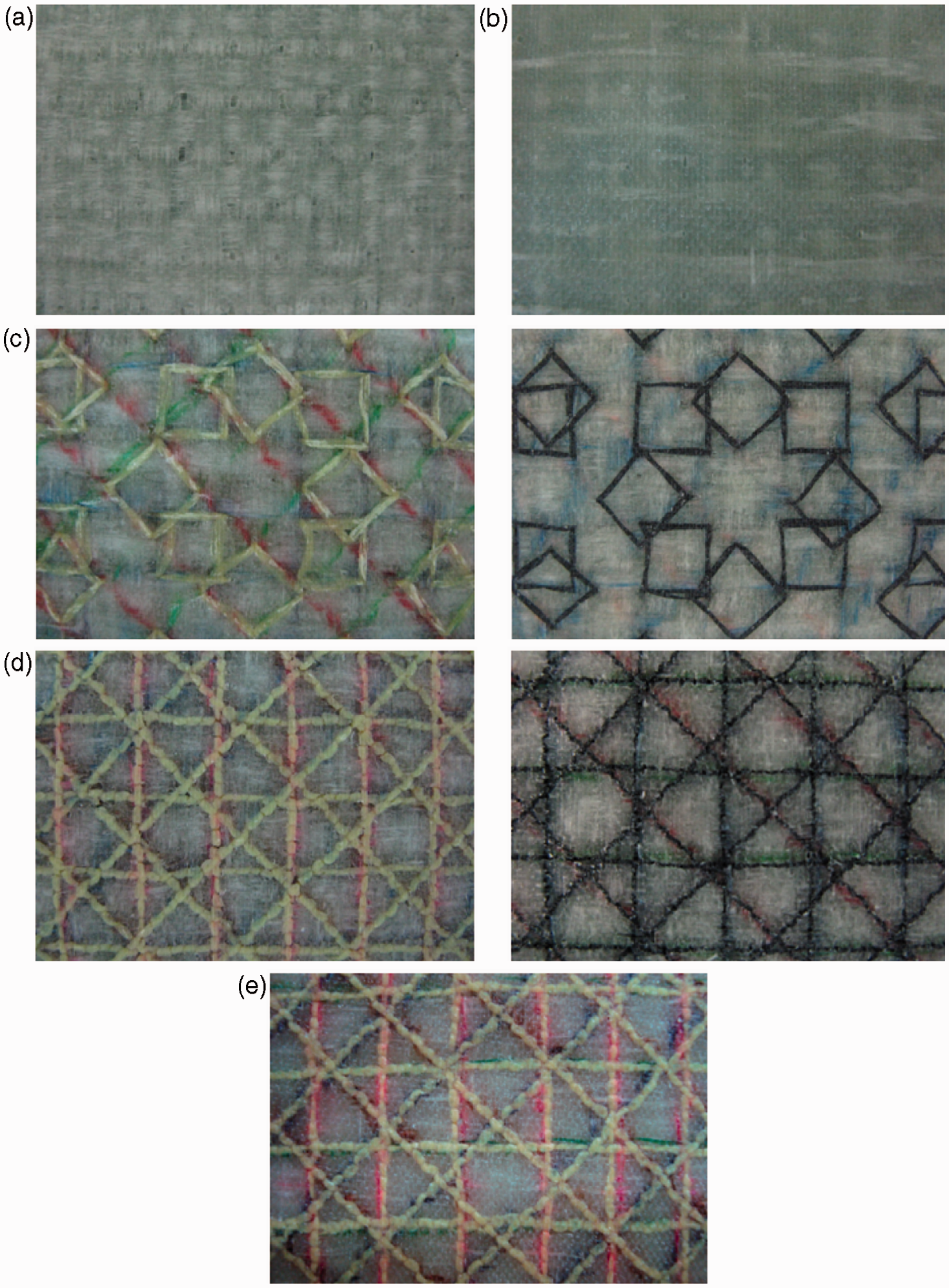
The density of the 2D unstitched and multistitched multilayer woven E-glass/polyester composite was determined by ASTM D792-91. The composite volume fraction and void content were also determined by ASTM D3171-99 and ASTM D2734-91, respectively. Before the bending test, the stitching area of the composite sample was examined by a scanning electron microscope (SEM) (LEO 440® model, UK).
Bending test
The three-point bending strength test of the composite structures was performed on a Shimadzu AG-XD 50 (Japan) tester equipped with Trapezium® software based on ASTM D790-90. The bending testing speed was 1.3 mm/min. The test dimensions were 25.4 (width) mm × 80 (length) mm. The L/d (support span length/thickness) ratio was 16/1. The bending load applied to each sample was the warp (0°) and filling (90°) directions, respectively. The warp and filling directional bending test was repeated 3 times due to limited test coupons. After the bending load was applied to the developed structures, the structures were examined by an optical microscope (Olympus SZ61, Japan). The fractured areas in each of the sample’s front surface were measured by an image analyzing software (Image Pro-Plus, MediaCybernetics, USA). The fractured area in the sample image was carefully determined by user. The total fractured area was drawn at its boundary. Then, the fractured area was measured. Formulations of specific bending strength, modulus, and strain were presented as follows, respectively


Results and discussion
Density and fiber volume fraction results
The density and fiber volume fraction results of 2D unstitched, unstitched/nano, multistitched, and multistitched/nano multilayer woven E-glass/polyester composites are presented in Table 4. The density, total fiber volume fraction, and the void content results indicated that partly stitching and partly VARTM process caused a local misalignment and uneven fiber–matrix-nano placement in the structure as shown in Figure 3. The stitching caused a local misalignment and uneven fiber placement during needle piercing to the preform structure. In addition, when the number of stitching directions in the structure increased, the stitching yarn volume fraction (Vsfw) increased depending on the stitching density and yarn types. However, the total volume fraction (Vtfw) of the structures did not increase proportionally due to the stitching. It can be considered that the stitching parameters in the developed composite structures were stitching direction, stitching density, and stitching yarn type.
SEM photos of 2D woven E-glass/polyester composite structures at 0° (warp direction). (a) Unstitched structure (T1a), (b) unstitched/nano structure (T2b), (c) hand stitched structure (T3i), (d) machine stitched structure (T4l), (e) machine stitched/nano structure (T5a). Density and fiber volume fraction results of various developed composite structures.

Bending results
The warp–weft directional bending test results on various developed unstitched and multistitched composite structures are presented in Table 5. Figure 4(a) to (d) shows some of the stress–strain curves of 2D woven E-glass/polyester unstitched, unstitched/nano, multistitched, and multistitched/nano composite structures on warp direction. The bending stress–strain curve of the unstitched/nano structure became slightly a steep curve, and a breaking point of the curve slightly increased which indicated a stiff material as shown in Figure 4(b). However, the bending stress–strain curve of the multistitched structure became slightly an inclined curve, and the breaking point of the curve sharply decreased, when compared to the curve in Figure 4(b), which indicated a ductile material as shown in Figure 4(c). Figure 5(a) shows the bending strength and the specific bending strength of 2D woven E-glass/polyester unstitched, unstitched/nano, machine stitched/nano, and hand stitched/nano composite structures. Figure 5(b) and (c) shows the bending strength and the specific bending strength of 2D woven E-glass/polyester hand stitched and machine stitched composite structures, respectively. Figure 6(a) shows the bending modulus and the specific bending modulus of 2D woven E-glass/polyester unstitched, unstitched/nano, machine stitched/nano, and hand stitched/nano composite structures. Figure 6(b) and (c) shows the bending modulus and the specific bending modulus of 2D woven E-glass/polyester hand stitched and machine stitched composite structures, respectively. Figure 7(a) shows the bending strain and the specific bending strain of 2D woven E-glass/polyester unstitched, unstitched/nano, machine stitched/nano, and hand stitched/nano composite structures. Figure 7(b) and (c) shows the bending strain and the specific bending strain of 2D woven E-glass/polyester hand stitched and machine stitched composite structures, respectively.
Some of the stress–strain curves of 2D woven E-glass/polyester composite structures on warp direction. (a) Unstitched structure (T1a), (b) unstitched/nano structure (T2b), (c) machine stitched structure (T4l), (d) machine stitched/nano structure (T5a). (a). Bending strength and specific bending strength of 2D woven E-glass/polyester unstitched, unstitched/nano, and stitched/nano composite structures. (b). Bending strength and specific bending strength of 2D woven E-glass/polyester hand stitched composite structures. (c). Bending strength and specific bending strength of 2D woven E-glass/polyester machine stitched composite structures. (a) Bending modulus and specific bending modulus of 2D woven E-glass/polyester unstitched, unstitched/nano, and stitched/nano composite structures. (b). Bending modulus and specific bending modulus of 2D woven E-glass/polyester hand stitched composite structures. (c). Bending modulus and specific bending modulus of 2D woven E-glass/polyester machine stitched composite structures. (a) Bending strain and specific bending strain of 2D woven E-glass/polyester unstitched, unstitched/nano, and stitched/nano composite structures. (b). Bending strain and specific bending strain of 2D woven E-glass/polyester hand stitched composite structures. (c). Bending strain and specific bending strain of 2D woven E-glass/polyester machine stitched composite structures. Warp and weft directional bending test results of various developed composite structures.


Bending strength
As seen in Figure 5(a) and Table 5, the warp–weft directional bending strengths of the 2D unstitched (T1a–T1c) woven E-glass/polyester composite structures varied from 394.73 to 285.37 MPa and from 370.27 to 282.39 MPa, respectively. The warp–weft directional bending strengths of the 2D unstitched/nano (T2a–T2d) woven E-glass/polyester composite structures varied from 472.86 to 346.18 MPa and from 374.90 to 278.74 MPa, respectively. The warp–weft directional bending strengths of the 2D stitched/nano (T5a–T5b) woven E-glass/polyester composite structures varied from 283.15 to 239.12 MPa and from 273.35 to 194.64 MPa, respectively. It was found that the specific bending strengths of all unstitched, unstitched/nano, and multistitched/nano structures were proportional to their warp–weft directional bending strengths. The warp–weft directional specific bending strengths of unstitched structures (T1a–T1c) were higher than those of the multistitched/nano structures (T5a–T5b) due to stitching caused filament breakages. When the amount of nano silica material in the unstitched E-glass/polyester composite structure increased from 2.5 to 7.5 wt. %, the warp–weft directional specific bending strengths of the T2a–T2c structures increased. In addition, the warp–weft directional specific bending strengths of unstitched/nano (T2c–T2d) composite structures were higher than those of the unstitched (T1a–T1c) structures.
As seen in Figure 5(b) and Table 5, the warp–weft directional bending strengths of the 2D hand stitched (T3a–T3i) woven E-glass/polyester composite structures varied from 354.30 to 234.99 MPa and from 367.69 to 245.10 MPa, respectively. It was found that the specific bending strengths of all hand stitched structures were proportional to their warp–weft directional bending strengths. The warp–weft directional bending strengths of the T3b, T3h, and T3d were slightly higher than those of the remaining hand stitched structures. This indicated that two directional carbon and Kevlar® 129 hand stitched composite structures showed a better bending strength performance compared to the four directional carbon, Kevlar® 129 and E-glass hand stitched composite structures. In addition, when the stitching direction increased from two to four directions, the warp–weft directional bending strengths of all hand stitched structures decreased.
As seen in Figure 5(c) and Table 5, the warp–weft directional bending strengths of the 2D machine stitched (T4a–T4l) woven E-glass/polyester composite structures varied from 432.25 to 219.81 MPa and from 367.97 to 208.57 MPa, respectively. It was found that the specific bending strengths of all machine stitched structures were proportional to their warp–weft directional bending strengths. In low modulus (stitching yarn Nylon 6.6) lightly–densely stitched structures, the warp–weft directional bending strengths of the T4a were slightly higher than those of the T4b and T4c, but the warp–weft directional bending strengths of the T4d were higher than those of T4e and T4f. In high modulus (stitching yarn Kevlar® 129) lightly–densely stitched structures, the warp–weft directional bending strengths of the T4g were slightly higher than those of the T4h and T4i. The warp–weft directional bending strengths of the T4j were higher than those of the T4k and T4l. It was found that the warp–weft directional bending strengths of densely stitched structures (T4d–T4f and T4j–T4l) were higher than those of the lightly stitched structures (T4a–T4c and T4g–T4i). Interestingly, it was found that the warp–weft directional bending strengths of low modulus (stitching yarn Nylon 6.6) lightly–densely stitched structures were higher than those of the high modulus (stitching yarn Kevlar® 129) lightly–densely stitched structures. In addition, when the stitching direction increased the warp–weft directional bending strengths of low (stitching yarn Nylon 6.6) and high modulus (stitching yarn Kevlar® 129) lightly–densely stitched structures decreased. Also, it was found that there was a slight difference between warp–weft directional specific bending strengths. Generally, the warp directional specific bending strength was higher than the weft directional specific bending strength.
Bending modulus
As seen in Figure 6(a) and Table 5, the warp–weft directional bending modulus of the 2D unstitched (T1a–T1c) woven E-glass/polyester composite structures varied from 16.06 to 8.81 GPa and from 14.06 to 9.57 GPa, respectively. The warp–weft directional bending modulus of the 2D unstitched/nano (T2a–T2d) woven E-glass/polyester composite structures varied from 17.70 to 14.33 GPa and from 15.78 to 12.22 GPa, respectively. The warp–weft directional bending modulus of the 2D stitched/nano (T5a–T5b) woven E-glass/polyester composite structures varied from 12.84 to 9.68 GPa and from 11.24 to 8.42 GPa, respectively. It was found that the specific bending modulus of all unstitched, unstitched/nano, and multistitched/nano structures were proportional to their warp–weft directional bending modulus. The warp–weft directional specific bending modulus of unstitched structures (T1a–T1b) was higher than those of the multistitched/nano structures (T5a–T5b) due to stitching caused filament breakages. When the amount of nano silica material in the unstitched E-glass/polyester composite structure increased from 2.5 to 7.5 wt. %, the warp–weft directional specific bending modulus of the T2a–T2c structures increased. In addition, the warp–weft directional specific bending modulus of unstitched/nano (T2c–T2d) composite structures was higher than those of the unstitched (T1a–T1c) structures.
As seen in Figure 6(b) and Table 5, the warp–weft directional bending modulus of the 2D hand stitched (T3a–T3i) woven E-glass/polyester composite structures varied from 15.67 to 12.67 GPa and from 15.82 to 12.03 GPa, respectively. It was found that the specific bending modulus of all hand stitched structures was proportional to their warp–weft directional bending modulus. The warp–weft directional bending modulus of the T3b, T3h, and T3d was slightly higher than those of the remaining hand stitched structures. This indicated that two directional carbon and Kevlar® 129 hand stitched composite structures showed slightly a better bending modulus performance compared to the four directional carbon, Kevlar® 129 and E-glass hand stitched composite structures. In addition, when the number of stitching directions increased from two to four directions, the warp–weft directional bending modulus of all hand stitched structures decreased. It was also found that there was a slight difference between warp–weft directional bending modulus.
As seen in Figure 6(c) and Table 5, the warp–weft directional bending modulus of the 2D machine stitched (T4a–T4l) woven E-glass/polyester composite structures varied from 18.11 to 11.08 GPa and from 16.21 to 9.50 GPa, respectively. It was found that the specific bending modulus of all machine stitched structures was proportional to their warp–weft directional bending modulus. In low modulus (stitching yarn Nylon 6.6) lightly–densely stitched structures, the warp–weft directional bending modulus of the T4a was slightly higher than those of the T4b and T4c, but the warp–weft directional bending modulus of the T4d was higher than those of T4e and T4f. In high modulus (stitching yarn Kevlar® 129) lightly–densely stitched structures, the warp–weft directional bending modulus of the T4g was higher than those of the T4h and T4i. In addition, the warp–weft directional bending modulus of the T4j was higher than those of the T4k and T4l. It was found that the warp–weft directional bending modulus of densely stitched structures (T4d–T4f and T4j–T4l) was higher than those of the lightly stitched structures (T4a–T4c and T4g–T4i). Interestingly, it was found that the warp–weft directional bending modulus of low modulus (stitching yarn Nylon 6.6) lightly–densely stitched structures was higher than those of the high modulus (stitching yarn Kevlar® 129) lightly–densely stitched structures. In addition, when the number of stitching directions increased the warp–weft directional bending modulus of low (stitching yarn Nylon 6.6) and high modulus (stitching yarn Kevlar® 129) lightly–densely stitched structures decreased. Also, it was found that there was a slight difference between warp–weft directional bending modulus. Generally, the warp directional bending modulus was higher than the weft directional bending modulus.
Bending strain
As seen in Figure 7(a) and Table 5, the warp–weft directional bending strains of the 2D unstitched (T1a–T1c) woven E-glass/polyester composite structures varied from 3.10 to 2.89% and from 4.12 to 2.73%, respectively. The warp–weft directional bending strains of the 2D unstitched/nano (T2a–T2d) woven E-glass/polyester composite structures varied from 3.29 to 2.33% and from 2.96 to 2.51%, respectively. The warp–weft directional bending strains of the 2D stitched/nano (T5a–T5b) woven E-glass/polyester composite structures varied from 2.94 to 2.60% and from 3.71 to 2.72%, respectively. It was found that the specific bending strains of all unstitched, unstitched/nano, and multistitched/nano structures were proportional to their warp–weft directional bending strains. The warp–weft directional specific bending strains of unstitched structures (T1a–T1c) were higher than those of the multistitched/nano structures (T5a–T5b), except weft directional strain of T1a, due to stitching. When the amount of nano silica material in the unstitched E-glass/polyester composite structure increased from 2.5 to 7.5 wt. %, the warp–weft directional specific bending strains of the T2a–T2c structures slightly decreased. In addition, the warp directional specific bending strains of unstitched/nano (T2c–T2d) composite structures were lower than those of the unstitched (T1a–T1c) structures.
As seen in Figure 7(b) and Table 5, the warp–weft directional bending strains of the 2D hand stitched (T3a–T3i) woven E-glass/polyester composite structures varied from 2.61 to 1.98% and from 2.71 to 2.18%, respectively. It was found that the specific bending strains of all hand stitched structures were proportional to their warp–weft directional bending strains. The warp–weft directional bending strains of the T3b, T3h, and T3d were slightly higher than those of the remaining hand stitched structures. When the number of stitching directions increased from two to four directions the warp–weft directional bending strains of all hand stitched structures decreased.
As seen in Figure 7(c) and Table 5, the warp–weft directional bending strains of the 2D machine stitched (T4a–T4l) woven E-glass/polyester composite structures varied from 2.87 to 2.14% and from 2.92 to 2.25%, respectively. It was found that the specific bending strains of all machine stitched structures were proportional to their warp–weft directional bending strains. In low modulus (stitching yarn Nylon 6.6) lightly–densely stitched structures, the warp–weft directional bending strains of the T4b were slightly higher than those of the T4a and T4c and also, the warp–weft directional bending strains of the T4d were slightly higher than those of T4e and T4f. In high modulus (stitching yarn Kevlar® 129) lightly–densely stitched structures, the warp–weft directional bending strains of the T4h–T4i were almost equal and they were slightly higher than that of the T4g. In addition, the warp–weft directional bending strains of the T4k were slightly higher than those of the T4j and T4l. It was found that the warp–weft directional bending strains of densely stitched structures (T4d–T4f and T4j–T4l) were almost equal compared to the lightly stitched structures (T4a–T4c and T4g–T4i). Interestingly, it was also found that the warp–weft directional bending strains of low modulus (stitching yarn Nylon 6.6) lightly–densely stitched structures were very close to the high modulus (stitching yarn Kevlar® 129) lightly–densely stitched structures. In addition, no significant differences were found between warp–weft directional bending strains of low (stitching yarn Nylon 6.6) and high modulus (stitching yarn Kevlar® 129) lightly–densely stitched structures by the increase of stitching direction. Also, it was found that there was a slight difference between warp–weft directional bending strains.
Failure results after bending test
Some of the failure results on various developed 2D woven E-glass/polyester unstitched, unstitched/nano, multistitched, and multistitched/nano composite structures after warp–weft directional bending test are presented in Table 6. Figure 8(a) shows the damaged areas and the specific damaged areas of 2D woven E-glass/polyester unstitched, unstitched/nano, and multistitched/nano composite structures after warp–weft directional bending load was applied. Figure 8(b) and (c) shows the damaged areas and the specific damaged areas of 2D woven E-glass/polyester hand stitched and machine stitched composite structures, respectively. Figure 9 shows the front face and the cross-sectional views of unstitched and unstitched/nano 2D E-glass/polyester woven composites. Figure 10 shows the front face and the cross-sectional views of hand stitched and hand stitched/nano 2D E-glass/polyester woven composites. Figure 11 shows the front face and the cross-sectional views of machine stitched and machine stitched/nano 2D E-glass/polyester woven composites.
(a) Damaged and specific damaged areas of 2D woven E-glass/polyester unstitched, unstitched/nano, and stitched/nano composite structures. (b). Damaged and specific damaged areas of 2D woven E-glass/polyester hand stitched composite structures. (c). Damaged and specific damaged areas of 2D woven E-glass/polyester machine stitched composite structures. Front face (digital photos, left) and cross-sectional (microscopic photos at ×6.7 magnification, right) views of unstitched and unstitched/nano 2D E-glass/polyester woven composites after bending test at (a) warp and (b) weft directions. Front face (digital photos, left) and cross-sectional (microscopic photos at ×6.7 magnification, right) views of hand stitched and hand stitched/nano 2D E-glass/polyester woven composites after bending test at (a) warp and (b) weft directions. Front face (digital photos, left) and cross-sectional (microscopic photos at ×6.7 magnification, right) views of machine stitched and machine stitched/nano 2D E-glass/polyester woven composites after bending test at (a) warp and (b) weft directions. Failure results of various developed composite structures after warp and weft directional bending test.


As seen in Figure 8(a) and Table 6, the warp–weft directional damaged areas of the 2D unstitched (T1a–T1c) woven E-glass/polyester composite structures varied from 290.43 to 197.90 mm2 and from 265.49 to 178.35 mm2, respectively. The warp–weft directional damaged areas of the 2D unstitched/nano (T2a–T2d) woven E-glass/polyester composite structures varied from 383.52 to 129.36 mm2 and from 331.29 to 138.18 mm2, respectively. The warp–weft directional damaged areas of the 2D stitched/nano (T5a–T5b) woven E-glass/polyester composite structures varied from 183.32 to 104.68 mm2 and from 287.41 to 133.81 mm2, respectively. It was found that the warp–weft directional specific damaged areas of unstitched (T1a–T1b) structures were lower than those of the unstitched/nano (T2a and T2c) structures but higher than those of the stitched/nano structures (T5a–T5b). The warp–weft directional specific damaged areas of T2d structure were very low when compared to the T2c due to nano carbon material.
As seen in Figure 8(b) and Table 6, the warp–weft directional damaged areas of the 2D hand stitched (T3a–T3i) woven E-glass/polyester composite structures varied from 375.22 to 152.10 mm2 and from 318.27 to 182.48 mm2, respectively. It was found that the specific damaged areas of all hand stitched structures were proportional to their warp–weft directional damaged areas. The warp–weft directional damaged areas of four directional Kevlar® 129 stitched structure (T3c) were lower than those of the one and two directional Kevlar® 129 stitched structures (T3a–T3b), whereas the warp–weft directional damaged areas of two directional E-glass and carbon stitched structures (T3e and T3h) were lower than those of the one and two directional E-glass and carbon stitched structures (T3d–T3f and T3g–T3i). This indicated that when the number of stitching directions increased, the warp–weft directional damaged areas of all hand stitched structures decreased.
As seen in Figure 8(c) and Table 6, the warp–weft directional damaged areas of the 2D machine stitched (T4a–T4l) woven E-glass/polyester composite structures varied from 294.26 to 107.62 mm2 and from 299.87 to 97.63 mm2, respectively. It was found that the specific damaged areas of all machine stitched structures were proportional to their damaged areas. In low modulus (stitching yarn Nylon 6.6) lightly–densely stitched structures, the warp–weft directional damaged areas of the T4a were higher than those of the T4b–T4f. The warp–weft directional damaged areas of the T4e were the lowest. In high modulus (stitching yarn Kevlar® 129) lightly–densely stitched structures, the warp–weft directional damaged areas of the T4h were higher than those of the T4g and T4i, and T4j–T4l. It was found that the warp–weft directional damaged areas of four directional densely stitched structures (T4f and T4l) were lower than those of the other multistitched structures. In addition, when the stitching direction increased, the warp–weft directional damaged areas of low (stitching yarn Nylon 6.6) and high modulus (stitching yarn Kevlar® 129) lightly–densely stitched structures decreased. The lowest warp–weft directional damaged areas were obtained from the T4l. Also, it was found that there was a slight difference between the warp–weft directional specific damaged areas in all structures. Generally, the warp directional damaged areas were higher than those of the warp directional damaged areas except T4a and T4i. It was generally found that when the number of stitching directions and stitching density in structures increased, their damaged areas decreased.
As seen in Figure 9, the failure of warp–weft directional 2D unstitched and unstitched/nano woven E-glass/polyester composite structures was observed as a form of matrix breakages, and partial or total fiber breakages in their front and back surfaces. In addition, the unstitched and unstitched/nano structure composites had delamination in their cross-sections. The failure of warp–weft directional 2D unstitched/nano woven E-glass/polyester composite structures showed more brittle behavior compared to the unstitched structures. When the amount of nano silica material in the unstitched E-glass/polyester composite structure increased, the damaged areas of the unstitched/nano structures were also increased.
As seen in Figure 10, the failure of warp–weft directional 2D hand stitched (T3a–T3i) and hand stitched/nano (T5b) woven E-glass/polyester composite structures was observed as a form of matrix breakages, and partial and complete filaments, and yarn (tow) breakages in their front and back surfaces. In addition, especially the T3c–T3e structures had a local delamination in their cross-sections and the delamination did not propagate to the large areas due to multiple stitching. The warp–weft directional bending load was confined at a narrow area in which the catastrophic failure led to the damage as a form of matrix breakages, fiber–matrix pull-out, and local multiple fiber breakages. In addition, it was found that the damaged areas of the multistitched structures were lower than those of unstitched structures due to multiple stitching. The damaged area of the T5b structure was lower than those of the unstitched, unstitched/nano except T2d and hand stitched structures, but it was higher than those of the machine stitched and the machine stitched/nano structures.
As seen in Figure 11, the failure of warp–weft directional 2D machine stitched (T4a–T4l) and machine stitched/nano (T5a) woven E-glass/polyester composite structures was observed as a form of matrix breakages, and partial and complete filaments, and yarn (tow) breakages in their surfaces. In addition, the T4l and T5a structures had a local delamination in their cross-sections and the delamination did not propagate to the large areas due to multiple stitching. The warp–weft directional bending load was confined at a narrow area in which the catastrophic failure led to the damage as a form of matrix breakages, fiber–matrix pull-out, and local multiple fiber breakages. In addition, it was found that the damaged area of the machine stitched structures was lower than those of unstitched, unstitched/nano, and hand stitched structures due to multiple stitching. However, the damaged area of the machine stitched/nano structures was lower than those of unstitched, unstitched/nano, hand and machine stitched, and hand stitched/nano structures due to multiple stitching. On the other hand, it was observed that the failure of warp–weft directional 2D machine stitched/nano (T5a) woven E-glass/polyester composite structures showed more brittle behavior. It could be considered that the both multistitched and multistitched/nano structures showed a damage tolerance behavior under the static bending load.
Conclusions
Two-dimensional multistitched and multistitched/nano E-glass/polyester woven composites were developed. Their bending properties were compared to 2D unstitched and unstitched/nano E-glass/polyester woven composites. The results indicated that stitching yarn type, stitching directions, stitching density, and amount of nano materials generally influenced the warp–weft directional bending properties of multistitched E-glass/polyester woven composites. It was found that the addition of nano silica in the stitched structures improved their damage resistance slightly. In addition, when the number of stitching direction and stitching density in structures increased, the damaged areas of the structures decreased.
The failure of all woven E-glass/polyester composite structures was matrix breakages, partial and complete filaments, and yarn (tow) breakages in their front and back surfaces. The unstitched and unstitched/nano structures had a complete delamination in their cross-sections, but the multistitched and multistitched/nano structures had a local delamination in their cross-sections and the delamination did not propagate to the large areas due to multiple stitching. The failure was confined at a narrow area due to multistitching and resulted as the catastrophic fiber breakages. This was considered that the damage resistance performances of the multistitched and multistitched/nano structures were enhanced due to stitching, in particular, at four directional stitching and addition of nano silica material.
Footnotes
Acknowledgements
The authors would like to thank the Scientific Research Department of Erciyes University for the invaluable support. The authors also would like to thank Erciyes University Technology Research and Application Center (TAUM) for the mechanical testing of the composite materials. In addition, the authors would like to thank Prof. Dr. Mustafa Guden for allowing the use of composite lab facilities in IYTE for this project.
Funding
This work was partly supported by Erciyes University Scientific Research Unit (EUBAP) under contract number EUBAPFBD-10-3383.