
Abstract
This paper deals with physical properties and compression behavior of new insole structure. This insole is developed based on a new 3D fibrous structure made of recycled polyester nonwoven (110 g/cm2) laminated with different textile materials by the use of a patented vertical-lapping process (VERTILAP®). To characterize physical and mechanical properties of the 3D structures, a methodology has been set up and new testing methods have been developed. The results of this study have shown interesting properties in terms of comfort and compression behavior (under static and dynamic loading). It has been observed that the 3D structure laminated with hemp woven fabric has the highest water absorbency, the highest thermal conductivity and the coolest touch effect compared to nonwoven made of a blend of polyester and viscose fibers. The compression behavior of the insole has been influenced by the physical properties of the 3D structure. The insoles developed in this work have a viscoelastic behavior with cushioning properties and can resist up to 218 kPa at 50% of deformation under static compression conditions and dissipate sufficient energy (higher than 180 N.mm) which allows the relieve of the foot pressure and distributes loads more evenly on the soft parts of the feet in use case.
Keywords
Introduction
The use of insoles in a shoe is designed to relieve pressure and distribute load more evenly on the soft parts of the feet, the leg and spinal joints. This is achieved by equalizing the pressure by the use of viscoelastic materials with cushioning properties. The primary attributes of the insole used in shoes are compression resistance under static and dynamic load, energy absorption, resilience, thermal comfort, water absorption and breathability. To insure these properties, the material used for insoles should be chosen correctly.
Many clinical studies have suggested that viscoelastic materials provide relief or prevention of a large number of incidents, including degenerative joint disease, muscle tears and stress fractures [1,2]. Transient skeletal forces have been attributed as the primary cause of many of these conditions. It has been demonstrated that these forces can be reduced by incorporating viscoelastic materials, i.e. cushioning material in the footwear, either in the construction of the shoes or as additions to shoes, such as insoles. Indeed, a number of studies have mentioned that viscoelastic materials in footwear interact with the natural heel pad and are capable of reducing the magnitude of the heelstrike transient during walking [3–5]. One of the most important properties of viscoelastic materials is their ability to reduce the magnitude of impact forces. This is achieved in two different ways: by extending the duration of the impact event and by absorbing energy created by the impact force which occurs at heelstrike (the ‘heelstrike transient'), when the heel contacts the ground at the beginning of the stance phase of gait [6].
These results are explained by the fact that the viscoelastic materials combine two different physical properties. The ‘viscous’ property implies that they deform slowly when exposed to an external force. The ‘elastic' property implies that once a deforming force has been removed, they return to their initial configuration. An important difference between elastic and viscoelastic materials under the heel is that viscoelastic materials return little or none of the momentum created by foot during the swing phase of gait, through the absorption of energy [6]. With viscoelastic materials, the material recovers from deformation over a period of time, and the energy which was used to deform it is largely converted to heat. The time course of this recovery depends on the properties of the viscoelastic material used in insole making.
Nowadays, materials used for insoles are micro cellular rubber (MCR), micro cellular polymer, silicon gel and polyurethane (PU) foams. The compression and resilience properties of these materials deteriorate with time, i.e. repeated loading in these materials causes the walls of the cells to collapse, leading to a loss of the material thickness, elasticity and energy absorption capacity. In addition, many types of foam have poor thermo-physical properties, are prone to antibacterial contamination and are difficult to recycle and re-use. Our strategy was to develop a new material for insole. To achieve this aim, the question of recycling and end of life utilization has been taken into account. This represents, in many industries, one of the main requirements and challenges in order to promote ecological methods of development in regard to new consumer sensibility towards environmental awareness.
In this work and based on all these facts, a new 3D fibrous structure made of recycled polyester (PET) material has been developed in order to produce new insoles for shoes. This new structure is produced using a novel patented process called VERTILAP® from N. SCHLUMBERGER Company [7]. In a previous study [8], it was shown that this 3D fibrous structure is more resilient and dissipates more energy than PU foams typically used for automobile industry. To characterize the physical and mechanical properties of new 3D fibrous structures for insole application, a new testing methodology has been developed. The results of this study have shown interesting properties of the new structure in terms of compression behavior (under static and dynamic loading) for comfort.
Materials and methods
3D structure processing
Three dimensional nonwoven products are available as STRUTO®, WAVEMAKER®, NAPCO®, MALIMO or MALIVLIES [9–11]. In the present study, a pleated 3D fibrous structure with viscoelastic properties has been obtained by the use of the VERTILAP process. This consists of a vertical lapping unit whereby a web or a thin sheet of nonwoven material is pleated to obtain a 3D structure.
The manufacturing process was carried out with a semi-industrial prototype (Figure 1). The pleated 3D fibrous structure was manufactured from a 110 g/m2 recycled PET nonwoven fabric (NF). The weight of NF was chosen based on preliminary pleating trials. The PET nonwoven is first vertically pleated and passed through a condensation zone. The 3D structure has been manufactured below the melting temperature of the PET web at 260℃. Then, those single 3D fibrous structures have been laminated using a flatbed laminating unit. During this step, a thermo adhesive nonwoven of 25 g/m2 copolyester nonwoven is incorporated to bind the single 3D fibrous structure and the laminating layers. The single 3D fibrous structure, the adhesive and the laminating layers are assembled and introduced in the system for heating at 110℃ with a conveyor belt speed of 5 m/min. After heating, the layers are slightly pressed together with pressure rollers of the laminating unit and cooled. This process provides thermal and mechanical stability of the multilayered structure, i.e. laminated 3D structure composed of three layers (Figure 2). The most important parameters during the laminating process are temperature, pressure of the rollers and the speed of conveyor belts.
The VERTILAP® process. The VERTILAP® 3D structure.

The raw materials used for manufacturing the pleated structure.

Characterization of the new 3D structures
Physical characterization
The sample sizes for the characterization tests were adapted to each standard method. The raw materials and the 3D fibrous structures for insole manufacturing have been characterized for thickness (T, mm), mass per unit area (M, g/m2) and air permeability (PAir, l/m2/s). The thickness of all samples was measured on the KES-FB3 compression tester of the Kawabata Evaluation System for Fabrics and the measurement conditions were as follow: the sample is compressed under a load of 0.05 kPa and a speed of 12 mm/min. The PAir was characterized with TEXTEST FX 3300 apparatus based on AFNOR G07-111 method. In addition, the pleated structures have been characterized by the number of pleats per cm (condensation ratio) which is adjusted during the manufacturing process, thermal conductivity (K, W/cm.℃) and warm/cool effect (qmax, W/cm2). The characterization of K and qmax were conducted with the KES-FB7 of the Kawabata Evaluation. The above mentioned tests were conducted at 20 ± 2℃ and a relative humidity (RH) of 65 ± 5%.
In many process techniques and end use characteristics, water absorbency of textiles materials is a key factor. The functional properties of such uses can be quantified by the absorption capacity and the absorption rate [12]. In this work, the water absorbency of the 3D structures, by capillarity, has been measured by a prototype machine developed in our laboratory [13]. Experimental set-up is shown in Figure 3. The device is composed of two reservoirs: an overflow reservoir and a buffer reservoir. The overflow reservoir is filled with water pumped from the buffer one. The sample (100 × 100 mm) was placed above a sintered (permeable) material put in contact with the overflow reservoir as shown in the insert of Figure 3. The sample is maintained under a pressure of about 3.4 kPa (500 g), chosen arbitrarily to have a sufficient contact with the sintered material (water source). An analytic balance (Metter AE160) was placed under the buffer reservoir to weight the absorbed water by the 3D structure during time. In order to avoid the water evaporation, the prototype machine was placed in a box under hygroscopic condition at 27 ± 2℃ and 95 ± 5% RH. Using the balance, the loss of liquid was monitored during the test. The water loss was defined as the difference between the input and the output of the two reservoirs due to water absorption by the fibrous structure. The test was stopped when the balance stabilized. The measurements have been collected in order to evaluate the water absorption rate (not presented here) and water absorption capacity after 23 min of test, a mean time of the balance stabilization observed in the case of tested structures. The water absorption capacity (Ab, %) was calculated using equation (1).
Absorption apparatus. The insert shows the sample’s position.

Mechanical characterization
Static compression load
The 3D structures were tested on a universal screw driven (Instron 33R4204) fitted with 5 kN load cell and set up with two compression circular platens of 100 and 150 mm in diameter. The size of all the specimens was 100 mm × 100 mm. Each specimen was simply attached to the surface of a fixed platen with adhesives in order to prevent possible outer layer movement. The mechanical characterization was carried out in the standard atmospheric condition maintained under dry condition at 20 ± 2℃ and 65 ± 5% RH, as it was reported that the compression resilience of NFs decreases under wet condition [14]. The static compression test was conducted at a speed of 0.05 mm/s under two conditions as appended below:
The sample is first compressed to 50% of its initial thickness then decompressed at the same speed until the plates are back to their initial positions. Then, there is 10 s wait in order to allow the sample to recover. Five cycles of compression/decompression are repeated. The sample is first compressed up to 20% of its initial thickness then decompressed at the same speed until the plates are back to their initial positions with a 10 s wait in order to allow the sample to recover. It is firstly compressed up to 50% of its initial thickness then decompressed at the same speed until the plates are back to their initial positions. Then, there is 10 s wait in order to allow the sample to recover.
During the test, time, displacement and load applied to the plate are measured. Five tests were carried out for each sample under the testing condition. For each compression cycle, the stress–strain curve presented an average of the five experimental results. In order to characterize the mechanical properties of these new 3D fibrous structure dedicated to insoles development, the maximum load and the absorbed energy at 20% and 50% of deformation have been evaluated and compared to data in literature [15].
Dynamic compression load
The dynamic compression (fatigue test) aims to evaluate the durability, i.e. the wear resistance, of the 3D structure used for insoles development. A fatigue machine developed by our laboratory is used for the fatigue test [16]. The principle of the machine is to submit the 3D structure to repeated cycles of compression/decompression by means of a disc connected to an animated mechanism of a reciprocating motion. The test consists the compression of the 3D structure at a deformation speed of 100 mm/s until 50% of deformation of the initial thickness during 5 h (9 × 10⁴ cycles). The thickness of the structure is measured and compression test (condition 2) is conducted on the sample. This test allows an understanding of the mechanical deformation mechanism of the 3D fibrous structure and the evaluation of its durability under the test conditions.
Results and discussion
Material selection for the insole top layer
The physical properties of the pleated structures.

Static compression
Typical compression stress–strain relationship and cushioning behavior
Figure 4 shows typical compression stress–strain curves of 3D structures. The samples A55 and A47 are taken as an example and compared to a 3D structure made of JH web. In order to introduce the cushioning properties, curve (F) represents the stress–strain curve of foam material [8]. To facilitate the analysis of the compression behavior of the 3D structure tested in this work, the compression process is divided into three different stages, i.e. initial stage (stage I), elastic and plateau stage (stage II) and densification stage (stage III) according to the changes in the slope of the curve. On the initial stage, a lower slope is observed due to the compression of the top layer leading to a slight slipping and rearrangement of fibers in this layer (Figure 4a). However, when the structure is further compressed in stage II, a rapid increase of the compression stress, i.e. a stiffer mechanical behavior of the 3D structure, is observed. In this stage, the pleats start to bend (Figure 4b) leading to the stiffening of the fibrous structure in the vertical direction, i.e. the compression direction. A nearly constant stress (a plateau) is observed in the case of the sample JH47. This sample is obtained using of the NHJ web which is more flexible than the JF web. It has been shown in a previous study that the compression behavior of this sample is similar to foam. In stage III, the deformation mechanism of the pleated structure is complex, which could be affected by the buckling, the shearing and the inter-contacting of the fiber in the same layer as well as the contacting of fibers from different layers of the 3D structure (Figure 4c) and consequently the swift densification of the entire structure. In the case of sample A55, it is clearly observed that pleats collapse and contact each other, and therefore a high stiffness is obtained leading to high compression resistance at 50% of deformation. These observations mean that a balance between compression resistance, obtained in the case of samples A47 and A55, and cushioning performance (a plateau stage) partially observed in the case of the sample A47, should be investigated. This means that an attempt to enlarge the plateau zone and reasonably control the compression stress ratio at the plateau stage, as illustrated in the curve (I), should be investigated throw optimization of the physical properties of the 3D structure (the type of pleated material, the thickness of the insole and the number of pleats/cm).
Typical compression stress–strain curve of the samples A47, A55 and JH47 (right) and the 3D structure deformation images (a, b and c) during the compression cycle (left).
Cyclic loading of 3D structure
Figure 5 displays the typical compression behavior under cyclic loading of the 3D fibrous structure. Sample A47 is shown as an example. These curves allow the evaluation of the maximum load at 50% of deformation and the calculation of the energy absorption which represents the area under the hysteresis cycle. The hysteresis cycle illustrates the viscoelastic properties of the new 3D structure. Then, for all products, a significant difference can be observed between the first and the others cycles (2nd, 3rd, 4th and 5th). During the first cycle, a rapid change in the thickness is due to high amount of fiber-to-fiber slippage in the 3D fibrous structure [18,19]. A permanent or delayed thickness deformation (Ti) is observed after the first cycle therefore this deformation decreases slightly with repeated cycling. To summarize, during the compression/decompression test of all samples, different steps of the compression behavior are observed: the contact surface is first compressed followed by buckling of the pleated structure. The existence of the compression hysteresis is due to the inter fibers friction. The hysteresis and the stabilization are not reached after the fifth cycle which means that the mechanical stability of the 3D fibrous structure is not reached at this level of compression cycles. This introduces the importance of the dynamic compression tests, i.e. durability tests.
Typical compression stress–strain curve (the sample A47).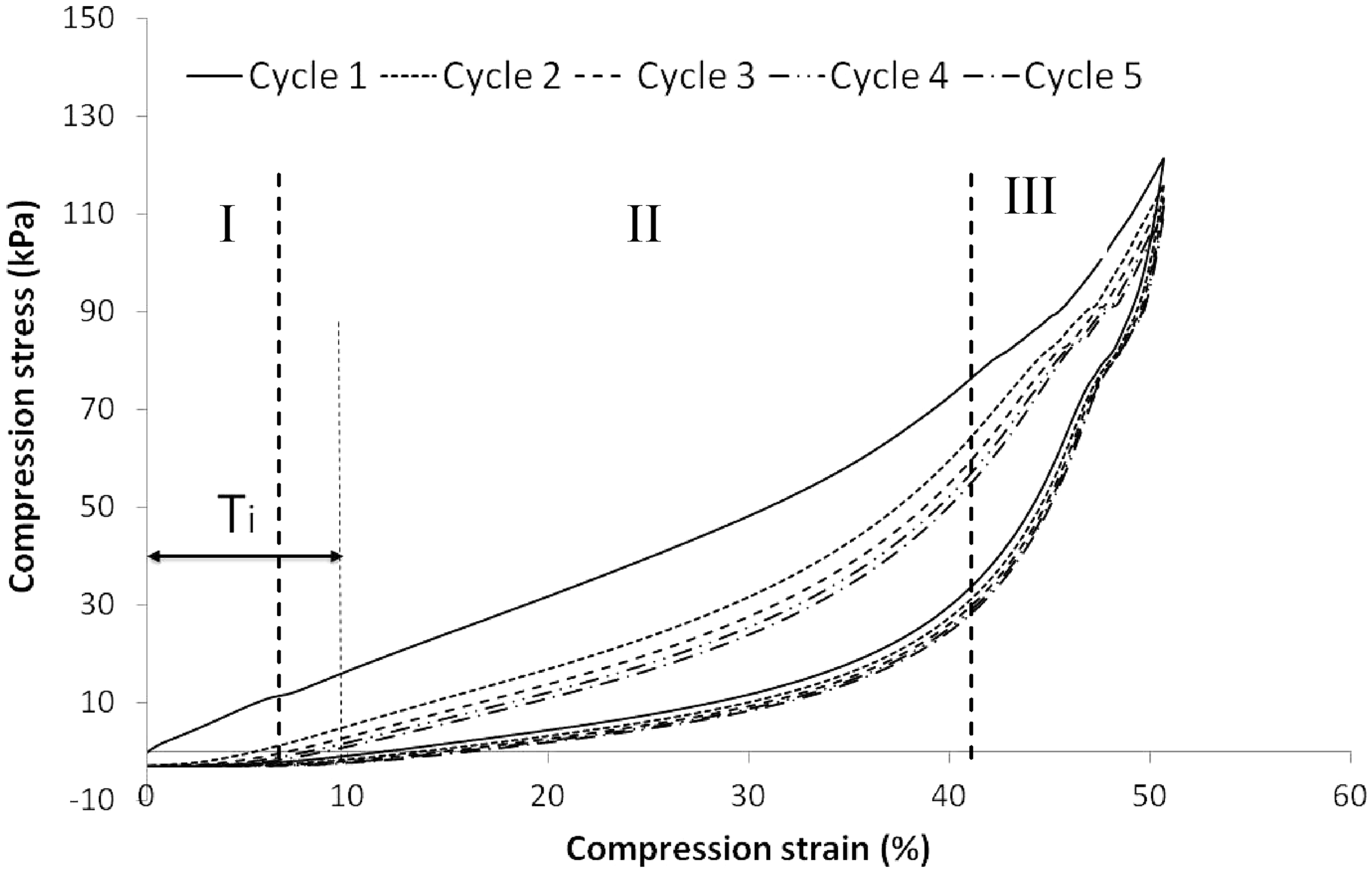
The above analysis shows that the 3D structure developed in this work exhibits a certain cushioning properties, because a slowly increasing compression stress in stage II is obtained until a large deformation corresponding to almost 40%. It should be noted that the compression test was conducted at a very low strain rate (3 mm/min). It was estimated that the 3D fibrous structure will not have exactly the same behavior at higher strain rates under loading. In our case, the absorbed energy calculated at low strain rate is used as a parameter to optimize the cushioning performance of the Vertilap structures dedicated to insoles development. It is necessary to point out that an optimum energy absorbing material should dissipate the impact energy, but keep the load below the limit allowed. Thus, two criteria should be considered. One is the amount of the energy needed to be absorbed by the deformation of the structure once the limit of compression resistance is reached and the other is the stress to be supported by the structure (the material). As shown in Figure 5, it can be observed that the energy absorbed by the sample is low in the densification stage, but the stress increases sharply. In this case of our end-use application, i.e. insoles product, it is preferable that the material dissipates all the energy before reaching the densification stage in order to ensure a good cushioning behavior. Thus, the amount of absorbed energy before the densification stage and the stress level at the plateau (stage II) should be two key parameters for optimization of Vertilap product in order to meet the requirements of insoles end-use.
Maximum stress applied at 50% of initial thickness deformation
A preliminary study has shown that the condensation ratio of the 3D structure (the number of pleats/cm) is the parameter which influences the maximum load at 50% of deformation the most. This parameter represents the resistance of the material to the compression solicitations, i.e. the material resistance to the heel pressure on insoles. In the case of A75, A52 and A55 samples, Figure 6 shows that the maximum load for the first cycle increases with the number of pleats while the thickness is maintained constant. In fact, sample A55 highlights better resistance to compression than sample A47 and withstands a compression load (218 kPa) at 50% of deformation equal to the pressure applied by the mid-foot (162 kPa) during the stance phase of gait [20]. Overall the 3D fibrous structures demonstrate good resistance to compression suggesting future potential use of this material for insoles application. In future, emphasis will be made to optimize the compression resistance of the new 3D structure which should resist at least to the pressure of the heel (863 kPa) for 0.2–0.3 s. This is equal to the period during which the heel is in contact with the ground [21]. In fact, the heel contact phase is approximately 20% of the gait cycle. For the case of slow walking, the gait speed is estimated between 0.97 and 1.59 m/s and the cadence is of about 45–65 steps/min [21–23].
Maximum load at 20% and 50% of deformation of the initial thickness.
Dissipated energy at 20% and 50% of initial thickness deformation
The resilience properties of the 3D structures, i.e. the total strain energy stored (absorbed) in the fibrous material, is studied. The comfort of the insoles is related to its capacity to absorb the energy created during the stance phase of gait. Figure 7 illustrates the energy at 20% and 50% of deformation absorbed by the samples A47, A52 and A55. It was observed that the sample A52 absorbs more energy than the sample A47. Despite the fact that the sample A55 resists to a higher compression stress than A52, it is indicating less energy dissipation. So, it can be concluded that a balance should be established between the compression load resistance and the energy absorption when manufacturing a structure for insoles application. A large variation of results has been found for the sample A55. This could be explained by the fact that the increase of the number of pleats per cm makes the structure stiffer and the behavior of the structure becomes less reproducible because of the stress induced inside the structure under high compression ratio. Regarding all samples, the cushioning energy is very satisfactory based on standard evaluation [24]. In fact, this standard mentions that for good cushioning material, the cushioning energy should be about 120 N.mm, during walking activity, and about 180 N.mm, during running activity. Our 3D structures absorb 10 times more energy than was required for insoles application.
Dissipated energy at 20% and 50% of initial thickness deformation.
Dynamic compression
In order to fulfill the durability requirement for insole applications, a clear understanding of the developed 3D structure response to cyclic compression loading is necessary through the evaluation of the thickness and the energy absorption evolution. To do so, the samples H2 and A55 are tested under the dynamic compression conditions. These samples were chosen based on optimal properties resulting from physical and static compression characterizations. First, the dynamic compression at 50% of deformation leads to a slight decrease of the thickness in the case of the samples H2 and A55 by 4.38% and 5.74%, respectively. This thickness loss can be explained by the fact that the vertical pleats of the 3D structure undergo a bending solicitation under repeated compression loading. This bending leads to the decrease of the pleats height. To then evaluate the durability of these structures, it is important to consider the loading conditions during walking. These conditions are related to the pressure and the contact time under each foot area during gait. A number of authors have estimated that normal subjects have a peak pressure beneath the foot of 200–500 kPa during the gait and that the contact time under the metatarsal area, for example, is about 0.6 s [21]. So, it can be admitted that our test conditions respect largely the contact time parameter. In fact, the compression/decompression cycle time in our test conditions is 0.2 s, i.e. the load impact contact with the tested samples is less than 0.2 s. This durability study was considered as a first step to evaluate our 3D structure mechanical behavior condition and further investigation with more severe test conditions will be the subject of future research work. Figure 8a presents the results of experimental investigation of the samples H2 and A55 response to dynamic compression loading in terms of absorbed energy. The results show a slight decrease of the absorbed energy at 20% of deformation of the initial thickness. The decrease of the absorbed energy (the resilience) can be explained by the fact that no significant damage occurs at the top layer of the 3D structure when the 3D structure is compressed up to 20% of its initial thickness. At 50% of deformation of the initial thickness, the absorbed energy decreases by 42.45% and 46.2% in the case of the samples H2 and A55, respectively. This means that the structural/mechanical weakening of the 3D fibrous structure has taken place in the pleats legs which were subjected to 9 × 10⁴ cycles of compression/decompression. It seems that the compression mechanism of the 3D structure, as illustrated in Figure 4b, is not the adequate one to maintain the compression resistance of the vertical product. The mechanism illustrated by the insert of the Figure 7b could be more resistant to fatigue test.
Dissipated energy at 20% and 50% of initial thickness deformation before and after the dynamic compression test (a) and the optimal compression mechanism of the pleats (b).
Conclusions
In this study, new 3D fibrous structures were produced with a patented verticalization process to be used as insoles in shoes. A new insole product has been developed with a strategy to satisfy the new European Directives of recyclability and reusability for textile industry by using a recycled PET nonwoven as raw material. These 3D structures have been tested using newly developed procedures and compared with results reported by different research studies in the field of plantar pressure relief.
The physical and geometrical parameters of the Vertilap product have small variability. Indeed, the use of regular textile as a feeding raw material and a semi-industrial process provide a good reproducibility of the structural parameters of the 3D structures. Based on physical characterization results of the tested samples, the mass per unit area of the 3D fibrous structures has to be decreased through the manufactured process for further investigations and in order to fulfill comfort related properties. The top layer materials made of natural fiber (Linen and Hemp) have shown an interesting structural property in terms of thermal conductivity, water absorption capacity and air permeability which make them a good candidate for insoles products with ecoconception-based development.
Compression behavior analysis indicates that the 3D fibrous structures have a good resilience property under static compression and they dissipate sufficient energy to be used for insole end-use. Under static compression conditions, the optimal insole structure withstands a pressure (218 kPa) at 50% of deformation equal to the pressure applied by the mid-foot (162 kPa) during the stance phase of gait. This can be explained by the fact that the vertical orientation of the fibers has the effect to provide maximum resilience to the material and lead to the reorganization of the fibrous structure under compression stress. Under dynamic compression conditions, the developed insoles with the number of pleats between 4.7 and 5.5 pleats/cm have shown a decrease of the absorbed energy between 42.45% and 46.2% at 50% of deformation of the initial thickness. In these cases, the thickness decreases by only 4.38–5.74%. Generally, these results highlight the relationship between the compressive mechanical behavior of these materials and their physical characteristics. So, the mechanical performance of the new insole developed could be improved by further optimization of the structural and physical properties of the 3D structure.
In conclusion, all these results underline the ability of the new pleated structure material to be used as insole to obtain sustainability. In spite of their interesting mechanical properties, these new 3D fibrous structures have to be improved. In fact, their mass per unit area and their thickness should be optimized in order to reach the key features of lightness, compression resistance and durability. This study still under progress and new finding will be presented in subsequent article.
Footnotes
Funding
This work was performed in the frame of the VERTILAP Research project supported by véhicule de future and Pole fibers, the competitiveness clusters. The authors gratefully thank the Alsace Region and OSEO for financial support and the MIPS laboratory for instrumental help.