
Abstract
A temperature sensing fabric is described, along with the manufacturing techniques required to produce the fabric on a computerised flat-bed knitting machine. Knitted sensing fabrics with copper, nickel and tungsten wire elements have been produced with resistances ranging from 3 to 130 Ω. The most successful samples have been created using textile-wrapped, enamelled wire and not only the textile character of the sensing element was enhanced, but also its tensile strength. A mathematical relationship has been derived between the temperature and resistance of the knitted sensors and this can be used to optimise its dimensions to achieve a targeted reference resistance. The temperature-resistance curves demonstrate a linear trend with a coefficient of determination in the range of 0.99–0.999 and can be integrated into garments to monitor skin temperatures.
Keywords
Introduction
In recent years, intensive research has been carried out in the area of electronic textiles, particularly in respect of the incorporation of sensing and actuating functions into textile products. Being close to the body, textiles can offer a comfortable, flexible platform for the embedding of sensing functions. The direct consequence of applying this technology is the development of wearable monitoring systems intended for continuous usage in monitoring the human body, for vital signs over extended periods of time. One of the key components of this system is the sensor which gathers data from the wearer and passes it for further processing. This information may be used to help creating a general health picture for various medical purposes [1]. Human body temperature is one of the four vital signs used in conjunction with heart rate, blood pressure and respiratory rate for medical assessment of the state of health. It is an important indicator of the physical condition of the human body and relates to comfort, performance, and heat or cold stresses [2].
Within the domain of wearable monitoring systems, most of the research has been focused in the development of textile-based electro-cardiography (ECG) and respiration sensors. To measure human body temperature, the majority of researchers have relied on commercially available temperature sensors (mainly thermistor and temperature measuring minute integrated circuits), which are usually attached externally to the garment [3–6]. Previous research also demonstrates that the fabrication of sensing fabric for temperature measurement has been little explored in a few individual studies [7–11].
De Rossi et al. [9] developed sensing fabric by coating a polypyrrole on a Lycra fabric; Locher et al. [10,11] developed a woven sensing fabric by incorporating insulated copper wires into a woven fabric and devising a routing technique; Ziegler and Frydrysiak [7] developed various types of textile thermocouple by utilising conductive fabric, non-conductive fabric and conductive yarn/wire and Sibinski et al. [12] developed a ‘thermistor yarn’ by depositing a thermo-resistive paste, on a polyvinylidene fluoride yarn. All of them are preliminary studies; their products were manufactured by cumbersome manual processes and are limited in their depth of characterisation and performance of the sensor in either the laboratory or in the real-life environment.
This study presents an improved method of embedding temperature sensing functionality into a textile substrate by using industrial scale textile process, and preliminary characterisation of its laboratory performance. The developed sensing fabric can be deployed for continuous measurement of the human body temperature in non-clinical settings, e.g. sports, military, general healthcare, firefighting situations and studies related to biorhythms and assessment of thermal strain in extreme environments.
Conceptualisation of temperature sensing fabric
In order to imbue a textile substrate with temperature sensing functionality, a detailed review has been conducted to identify what are currently the most commonly used temperature sensing technologies, i.e. the resistance temperature detector (RTD), thermistor and thermocouple.
Thermistors are fragile semiconductor devices, usually encapsulated in glass, whose resistance varies as a function of temperature [13]. Thermocouples are made of two dissimilar conducting wires which have been welded together and require relatively complex ‘conditioning’ electronics. Neither thermistors nor thermocouples are as accurate as the RTD [14]. The RTD measures temperature by correlating the resistance of a fine coiled wire (wrapped around an insulator) which changes with the temperature. The wrapped wire is further protected from the environment by placing it inside a sheathed probe [15].
The review has demonstrated that the RTD is probably the most suitable type of temperature sensor, whose design can be integrated into a textile substrate and could ultimately be fabricated on an industrial scale by a fabric forming machine with minimal manual input. The associated electronic circuit (to measure resistance) is also relatively simple. Thermistors and thermocouples, in contrast, have to be sewn into the fabric and do not become part of the cloth.
Technically, textile-based RTD sensors can be developed by integrating a piece of metal wire (as a sensing element) into a textile fabric. However, various factors have to be taken into account. For example, an appropriate alloy for the sensing element and the most appropriate material for the base fabric have to be selected. The most suitable textile structure for embedding the sensing element must be found. It is also necessary to identify which textile process is most appropriate for undertaking the manufacture.
Embedding of metallic wires into textile structures for sensing purposes has been documented by several researchers. Various fabric forming techniques such as knitting, weaving and embroidery have been exploited for these purposes. Various forms of stainless steel wire have also been used to develop textile-based ECG electrodes [16–18] and pressure sensors [19]. An elastic belt with embedded copper wire has been developed for inductance plethysmography-based respiration sensing [17]. A number of studies have been conducted in respect of the development and characterisation of routing methods for power and signal transmission in woven electronic textiles, by introducing networks of metallic wires at specified distances along the warp and weft [19–23].
Both knitted and woven fabrics have been used for the development of sensors and as sensing platforms for wearable health monitoring systems [24, 25]. However, in those sensor applications where close contact to the body is required, e.g. respiration or ECG sensors, the knitted structures are usually preferred over woven structures due to their ability to conform to body shape. Moreover, the breathability of knitted structures makes them comfortable to wear. The knitting technology offers significant advantages over other fabric forming systems in respect of the development of textile sensors [26], e.g. simple preparatory processing, the processability of a wide selection of conductive yarns, one-step garment manufacturing and exact positioning of sensing patches in the garment. Considering the above-mentioned benefits and the required application (human body skin temperature measurement), the knitting technology has been found to be an obvious choice to produce a temperature sensing fabric (TSF) by embedding a sensing wire into a knitted structure.
TSF has therefore been developed by embedding fine metallic wire into the structure of textile material on a computerised industrial flat-bed knitting machine. The operational principle of the TSF is based on the inherent propensity of metal wire to respond to changes in temperature with corresponding variation in its electrical resistance. A modified relationship between the resistance of the TSF and temperature has also been established. Various types of the metal wire identified as potential sensing elements for the TSF were compared in conjunction with the selection criteria. The TSF samples were tested under laboratory conditions within the temperature range of 20–50℃, to observe the relationship between the temperature and the resistance of the sensing fabric. The resistance–temperature (R–T) relationship demonstrates a linear trend with a coefficient of determination (r2-value) of over 99.9%.
Materials and methods
Figure 1. presents the concept of the TSF showing a metal wire inlaid in the middle of a rib knitted structure. By supplying a constant current to the inlaid wire and measuring the resulting voltage drop across it, its resistance can be calculated, and the temperature can be determined.
TSF showing inlaid sensing wire in a rib knitted structure.
The temperature–resistance relationship
The standard equation showing the relationship between the resistance of metal wire and its length, diameter and resistivity is stated in equation (1) [14]:


The sensing element
In RTD sensors, a very fine and relatively short sensing element (platinum wire of less than 25 µm in diameter) is employed, which changes its resistance upon change in temperature. Although platinum is the most commonly used sensing element in RTDs, copper- and nickel-based RTDs are also available in the market. Various metal wires could be used as the sensing elements of TSFs in the form of bare wire, enamelled wire or textile wrapped (braided) wire. The desirable properties for the sensing element of a TSF include the following items:
Table 1 presents the important properties of sensing elements i.e. platinum, nickel, tungsten and copper. For ease of understanding, these properties are also compared relatively in Figure 2. Platinum exhibits the highest resistivity of the range of metals. Therefore, a sensing element made of platinum would require a reduced length in order to achieve any desired nominal resistance; but copper would require a much longer length to achieve the same nominal resistance. High resistivity, along with a high-temperature coefficient of resistivity, also contributes to high sensitivity, as exhibited by both the nickel and platinum elements. Because of their low thermal mass, the response time of tungsten and platinum would be faster than nickel and copper. The tungsten is the strongest sensing element, in terms of its tensile properties. This would be beneficial for processing on a knitting machine. The platinum is regarded as the best sensing element for RTDs due to its high sensitivity, low thermal mass, its availability in its purest form and its stability over a wide range of temperatures; however, it is relatively expensive.
Comparative chart of important relative properties of TSF sensing elements. TSF: temperature sensing fabric. g of sensing element. 1 m long sensing element with diameter of 100 µm.

In terms of price, copper is the least expensive of the viable sensing elements and is readily available in range of diameters in bare and insulated form. The tungsten and nickel elements may not be readily available in their purest form which may result in large variations in the values of resistivity and the temperature coefficient of resistivity when purchased from different sources. In comparison to copper, it is relatively difficult to find tungsten and nickel sensing elements of the required purity and diameter so they might have to be manufactured by order.
Sensing elements of temperature sensing fabric.

A high purity grade of nickel.
Solderable polyurethane 156℃ enamel.
Double artificial silk covered.
Double nylon covered.
TSF structure and manufacturing
The main requirement of the TSF structure includes the smooth embedding of wire in the middle of the textile layers so that it neither contacts itself, nor protrudes from the main body or the edges of the fabric. It was also desirable to pack a high density of wire in order to achieve high nominal resistance in a small-sized TSF. The most suitable way for smooth embedding of wire into knitted structure is by the inlaying technique which involves trapping the inlay between the needle and the sinker loops on a double needle-bed machine. This technique offers the possibility of introducing those yarns which are difficult to process in the knitting machine due to their physical properties.
Various types of knitted structure can be used as a platform for laying-in metal wire. Double layer knitted structures are more suitable than single layer structures due to their better cover for the metal wire from wear and tear. Secondly, the metal wire would not be visible and does not affect the aesthetic properties of the fabric. Moreover, the wire will assume a straight configuration which avoids any distortion or flow towards an area of the fabric under tension.
In order to meet the requirement, a double layer structure of the TSF was devised using Shima Seiki Knit design software as shown in Figure 3; it comprises knit courses, spacer courses and metal inlays. The samples were fabricated on a 10 gauge Shima Seiki flat-bed knitting machine (as shown in Figure 4) by employing two feeders. First feeder was responsible for knitting spacer and knit courses, by taking five ends of highly textured 167 decitex polyester yarn, as drawn in blue lines. The second feeder was used for inlaying metal wire along with three ends of the same polyester, as shown by the magenta lines. It was difficult to pack the sensing element in every course of fabric without it shorting to itself. Therefore, a few courses of spacer yarn were introduced to keep the sensing element separated in between courses. After much experimental manipulation of the spacer, knit and inlay densities, the highest element concentration that was successfully achieved was of 46 wire inlays in an 8 × 8 cm2 knitted TSF structure (≈3.8 m length of element) as shown in Figure 5. The structure had to be constantly varied to achieve such a high density whilst avoiding the shorting of adjacent wires and minimising the protrusion of wire along the edges. For ease of understanding, the concept of the TSF structure may be represented in a simplified form by reducing the number of knitting and spacer courses as shown in Figure 6.
Needle notation of temperature sensing fabric designed in Shima Seiki Knit Paint. Shima Seiki computerised flat-bed knitting machine. TSF sample of 8 × 8 cm2 sensing area along with a magnified view of the knit structure. A schematic representation of temperature sensing fabric course notation.


The TSF sample comprised 39 wales; 33 for the inlay area and six for the edges. Since it is a double layer structure, 39 needles on the front needle bed and 39 needles on the lower needle bed were utilised. The non-sensing part of the TSF comprised full cardigan stitch (top and bottom) to minimise relaxation of the fabric. Samples developed with various types and thicknesses of metal wire (as mentioned in Table 2) provided a useful range of nominal resistances from 3 to 130 Ω.
The wires purchased from the various manufacturers were on small spools due to the shortness of the length. It was not prudent to use these small spools directly on the knitting machine because of two problems. Firstly, excessive wire breakage occurred due to interaction with the flanges of the spool while withdrawing the wire strand. Secondly, it was difficult to maintain constant tension in the wire. In order to address these issues, the metal wire was wound manually on a hank winder from small spools as shown in Figure 7.
Wire transfer from small spool to hank winder.
Care was exercised while winding on the hank winder in order to maintain constant tension in the wire. The hank winder was fastened to a stand and placed at the top of the machine.
Smooth withdrawal and constant tension in the feed material is a prime requirement for inlaying. In the initial phase of manufacturing, frequent breakages of the wire were experienced. Occasionally, extensive tension in the wire and interference between the needles and the slack wire caused issues. Reduced tension in the wire was also responsible for excessive bending at the fabric edges which resulted in wire protruding from the edges and sometimes from the main body of the knitted sample.
In order to rectify this issue a number of remedial actions were implemented:
The wire feed was moved to the side from the top of the machine; this reduced the angular path, resulting in more uniform tension and smoother feeding. A negative let off mechanism was developed at the hank winder, comprising tension plates and a spring system, to minimise discontinuities in the feed and to ensure even tension in the wire before, after and during inlaying. Extra polyester yarn was used as an inlay along with the metal wire to increase the strength of the inlay. A special feeder (see Figure 8) was used to inlay the metal wire, as the ordinary feeder did not meet the fundamental requirements of straight laying-in and smooth bending of wire at the edges of the TSF. This special feeder was tubular and was set at a lower height than the machine bed so that during the knitting cycle, the needles go over the wire without causing breakages. This inlay feeder must not be used for knitting as it would crash into the needles because of its lower adjusted height. The stitch presser was not used due to the risk of it interfering with the inlay wire. The special feeder responsible for metal inlaying was programmed to run at an extremely slow speed of 0.05 ms1. Special feeder for wire inlay.

Results and discussion
Processability of metallic wire during TSF manufacture
Metallic wire processability during temperature sensing fabric manufacture.

It was observed that the frequent wire breakages were related to excessive tension whilst poor quality of inlaying was related to slackness in the wire. For smooth bending of the wire at the edges, and a straight configuration of inlay, relatively high tensions were found to be preferable; considering that the wire was able to sustain them. That is the reason that coarser wires (over 100 µm) such as BEC150, EC150, C150, NC127 and NC125 showed better overall processability than their finer counterparts.
Among the medium diameter wires, i.e. N100, N90 and W80, nickel wires demonstrated smooth bending at the edges (because of its high ductility) but slightly more breakages (because of its low tensile strength) in comparison with tungsten wire. The tungsten wire is inherently strong and brittle in nature; therefore, inlaying of W80 suffered fewer breakages but displayed the poor behaviour in respect of bending at the edges.
The fine diameter wires such as BEN61 and W50 showed contrasting behaviour. Although the metallic core diameter of the BEN61 wire is 61 µm, due to its increased tensile strength resulting from the addition of the enamel and the braiding layers, the wire showed good processability during manufacture. The 50 µm tungsten wire suffered the highest number of breakages and was found to be relatively difficult to handle and to set into the feeder, as it gathered whenever any breakage occurred. In some of the samples, wire protruded from the surface of the edges, as shown in Figure 9.
A W50 temperature sensing fabric sample showing Tungsten wire protruding near the edges.
RTDs are commonly specified with their nominal resistance which is usually 100 Ω at 0℃. In order to achieve 100 Ω a very fine and relatively short sensing element (<25 µm in diameter) is employed in the RTDs. Similarly, it was desirable to produce TSF samples with high nominal resistance, which can be achieved by employing very fine metallic wires. However, the results of the TSF manufacturing demonstrated that it would be difficult to process the finer wires in the knitting machine. This problem was solved by replacing a bare sensing element with a braided–enamelled sensing element. The textile wrapping around the wire improved not only the textile character of the sensing element but also its tensile strength. Insulation would help in protecting the sensing element from external influences such as moisture and corrosion.
TSF structure
All TSF samples were made of polyester as a base material with 46 inlays of sensing element. The TSF structure was finalised following numerous development cycles, in order to meet the fundamental requirement of smooth embedding of sensing wire in the middle of fabric, without electrical short circuits. The developed TSF structures may not be the fully optimised one but the structures do meet the basic requirements of the research.
Highly textured polyester yarn was employed as the base material of the TSF. Polyester was preferred over cotton because of its extremely low moisture regain and high tensile strength. The low absorbency and good wicking properties of polyester fabrics assist the transfer of moisture from the skin to the outer surface of a garment where it evaporates. Moreover, the textured characteristics of the yarn increased the fabric bulkiness and provided better cover of the sensing element.
Modified temperature–resistance relationship
A modified temperature–resistance relationship for the TSF in terms of its dimensional parameters could be used to optimise the dimensions of a TSF patch for a required reference resistance. That will facilitate the specification and visualisation of the sensor characteristics. For example, the nominal resistance of an 8 × 8 cm2 TSF could be calculated. Similarly, the area of TSF could be predicted that would be required in order to make a 100 Ω sensor. The derived relationship in equation (2) between the length of sensing element and the dimensions of the TSF is only valid for rectangular sensing areas.
Manufacturing variation
The variations among the TSF samples may (manufacturing uncertainty) be represented in terms of their nominal resistance, however, for ease of understanding and to simplify comparison, the nominal resistance was converted into a calculated length of sensing element. The length of the sensing element 
The calculated length of sensing element was also compared with the target length 
After inserting the 8 × 8 cm2 dimensions and 46 inlays into equation (7), the target length of the TSF samples was calculated to be 3.8 m.
Figure 10 presents the uncertainty amongst various sample types in terms of the calculated length of inlaid sensing element. Variations within the sample type are expressed by error bars of standard uncertainty. It is evident from Figure 10 that length variations exist not only amongst the various sample types but also within examples of the same sample type. It can, nonetheless, be seen that the mean of the calculated length is found to be relatively close to the target length. In all the TSF samples, the 95% confidence deviation of the calculated length from its mean was found to be less than ±4 cm; which is not substantial considering the tolerance of the manufacturing process of the TSF samples. However, ±4 cm variations in the length of the sensing element will shift the reference resistance of a particular TSF sample. This means the TSF samples may not be used as interchangeable sensors; or, the calibration equation for one sample may not be applied to another sample. In other words, each individual sample should be calibrated before using it in an application environment.
TSF manufacturing variations in terms of length of sensing element.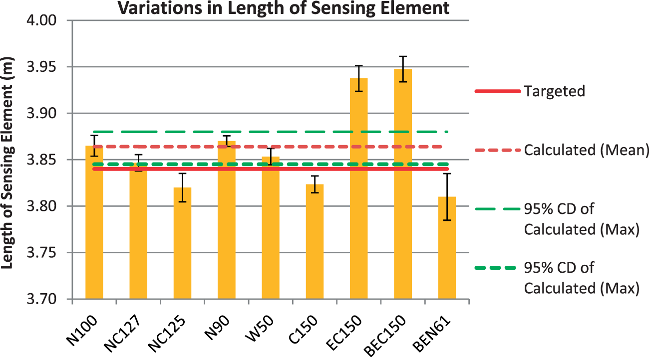
R–T testing
In order to calibrate the TSF samples, a laboratory oven with temperature homogeneity of ±1℃ was employed to create a steady thermal environment at the temperature points of 30℃, 40℃, 50℃ and 60℃. An Agilent multimeter with a four wire resistance measurement setup was used to measure resistance at steady temperature points. The reference resistance (R20) of the samples was measured at a room temperature of 20℃ using the same Agilent multimeter.
Experimental R–T curves of all the TSF samples show a linear relationship. One such relationship belonging to sample N100 is shown in Figure 11. The R–T data from all the samples have been curve-fitted with straight line equations. Variance between the data points and the fitted line has been calculated with a coefficient of determination (r2-value). The r2-values of all the experimental repeats of TSF samples were found to be in the range from 0.99 to 0.999.
Temperature–resistance relationship of a TSF sample (N100).
Figure 12 presents the resistance-ratio curves of all the samples. The resistance ratio was calculated by dividing the fitted resistance Resistance ratio curves of TSF samples in the temperature range of 20–50℃.
All the samples with the same kind of sensing element wire followed the same trend with insignificant sample-to-sample variations as shown in Figure 12. As expected, nickel-based TSF samples exhibited higher values of resistance ratio in comparison with the copper- and tungsten-based TSF samples.
Due to the higher nickel sensitivity, within the category of copper-based TSF samples, the nickel-coated copper-based TSF samples showed marginally higher resistance ratios in comparison with the pure copper-based TSF samples.
Conclusions
This paper presents the concept of TSF (a textile-based RTD) and the manufacturing techniques required to produce it on a standard industrial computerised flat-bed knitting machine. The TSF samples were produced with nominal resistances ranging from 3 to 130 Ω by using copper, nickel and tungsten wires of different diameter. Coarser sensing wires showed better overall processability in comparison to their finer counterparts. However, the coarser wires significantly reduced the overall sensitivity of the TSF. This problem was solved by replacing a bare wire with a braided, enamelled wire. The textile wrapping around the wire improved not only the textile character of the sensing element but also its tensile strength. A modified mathematical relationship between the temperature and resistance of a TSF was derived. This relationship can be used, to design sensing fabric with optimised dimensions, in order to achieve a targeted reference resistance. Manufacturing uncertainty (sample-to-sample variation) was found to be ±4 cm in terms of the length of the sensing element. The R–T curves showed a linear trend with a coefficient of determination in the range of 0.99–0.999. The resistance ratio curves described the insignificant sample-to-sample variations. The TSF can be integrated into garments for continuous measurement of human body temperature in non-clinical settings, e.g. sports, military, general healthcare, firefighting situations and studies related to biorhythms and assessment of thermal strain in extreme environments.
Footnotes
Funding
The authors would like to acknowledge the funding provided by the NED University of Engineering & Technology, Pakistan through the Higher Education Commission of Pakistan, to carry out this study.