
Abstract
Objective:
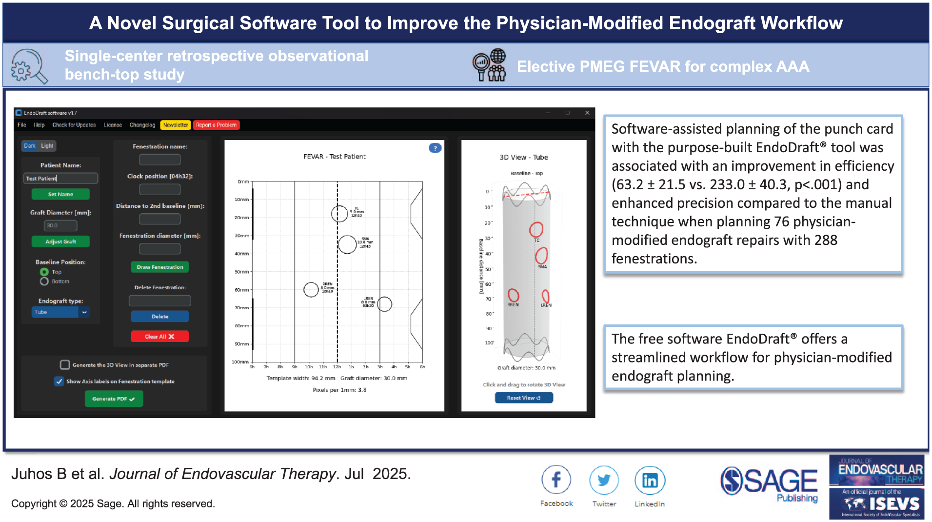
Three-dimensional models are increasingly used to facilitate the positioning of fenestrations on a physician-modified endograft (PMEG) during the fenestrated endovascular aortic repair (FEVAR) of complex abdominal aortic aneurysms (CAAA). The punch card technique was developed to eliminate the 3D printing workflow while preserving the benefits of having a 3D model. The objective of the current study is to evaluate the performance of the purpose-built software EndoDraft compared to manual punch card design.
Methods:
An experimental study was performed to compare software-assisted and manual punch card creation. Fenestration data of readily available procedural plans were used for patients who underwent elective FEVAR for CAAA from May 2023 to September 2024. Time needed to complete punch card planning was recorded as well as inaccuracies of the manual technique were evaluated by measuring the vertical and circumferential position of the fenestrations on the punch card.
Results:
A total of 76 punch cards and 288 fenestrations were made based on 38 patients’ fenestration data. Preparation time was 233.0 ± 40.3 seconds for the manual group, whereas 63.2 ± 21.5 seconds for the software-aided group (p<0.001). Longitudinal imprecision of the manual punch card was 0.8 ± 0.6 mm for the celiac axis (CA), 1.0 ± 0.6 mm for the superior mesenteric artery (SMA), 0.8 ± 0.5 mm for the right renal artery (RRen), whereas 1.0 ± 0.6 mm for the left renal artery (LRen). Circumferential errors of the same fenestrations were 0.4 ± 0.4 mm for the CA, 0.4 ± 0.4 mm for the SMA, 0.6 ± 0.5 mm for the RRen, and 0.5 ± 0.4 mm for the LRen. No significant difference between the completion time recorded at the beginning and at the end of the software’s learning curve was detected (77.8 ± 29.4 s vs 55.8 ± 18.5 s, p=0.15).
Conclusions:
The software-assisted design of the punch card is associated with higher precision and a vast improvement in speed compared to the manual technique during PMEG planning for the endovascular treatment of CAAAs. The purpose-built EndoDraft tool was made freely available in an online repository offering a more streamlined workflow.
Clinical Impact
EndoDraft® could meaningfully streamline the PMEG-FEVAR workflow by replacing manual punch-card drafting with rapid, software-generated, proportionally scaled templates that are produced in about one minute rather than several minutes, while reducing the small but measurable positioning errors inherent to hand drawing. For clinicians, this means a more reproducible planning step, less cognitive load and “ruler time” during preparation, and a workflow that is easier to standardize across operators with a short learning curve. The key innovation is purpose-built automation with integrated 2D/virtual 3D visualization and direct PDF output, made freely available to support wider adoption.
Keywords
Introduction
Fenestrated endovascular aneurysm repair (FEVAR) is widely accepted as a first-choice endovascular treatment of juxtarenal complex abdominal aortic aneurysms (CAAAs).1,2 Physician-modified endografts (PMEGs) are increasingly used as an alternative to custom-made devices (CMDs), either because of access restrictions of such devices or to overcome their lengthy manufacturing time in urgent clinical settings.3–5
Three-dimensional printed models of the visceral aortic segment are often used to facilitate the positioning of the fenestrations during the PMEG procedure.6,7 While the clinical benefits of using a 3D model over manual arc length measurements are yet to be proven, it might be beneficial in terms of preparation time and can help to avoid struts crossing the fenestrations, the latter often leading to strut modifications, thus potentially hindering treatment durability.8–10 The punch card technique was developed to simplify workflow and to overcome the time-consuming process of 3D printing, where the temporal constraints of the clinical course render this essential. 11 While there were efforts to automate PMEG planning, these software tools are commercially unavailable.10,12 EndoDraft is a software tool that was purpose-built to automate the process of punch card creation, eliminating the risk of human error and significantly shortening production time, while also providing both 2D and virtual 3D previews of the design to support and streamline the planning workflow. 13
This study aims to compare the precision and the production time of manual and software-based punch card creation to aid multi-vessel fenestrated PMEG procedures.
Methods
A benchtop experimental study was performed to compare 2 methods of punch card creation: the currently used manual technique and a software-assisted approach using a purpose-built software developed by the authors. 14 Experiments were executed using the fenestration data of readily available procedural plans of consecutive patients who underwent elective FEVAR for juxtarenal CAAA in an aortic referral center from May 2023 to September 2024. The study was conducted in compliance with the Declaration of Helsinki. The study protocol was approved by the local ethics committee (129/2024).
Data needed for creating the punch card was collected: diameter of the endograft; number of fenestrations; distance to proximal edge, clock position, and diameter of each fenestration. Manual and software-aided creation of the punch card was performed by 2 operators.
The Punch Card Technique
Translating the planned fenestrations onto a physical device while accurately maintaining their relative position is a key step in the PMEG workflow. Most operators use manual measurements in longitudinal and circumferential dimensions with a ruler on the device itself. With this technique, it can be challenging to keep the fenestrations free of any crossing struts, especially during multi-vessel FEVAR. The punch card is a physical tool that simplifies this translation of the planned positions onto any kind of aortic component, without the need to include a 3D printing workflow. 11 Prior to the operation, a proportionally scaled fenestration diagram is printed on a printable transparency with a standard office printer. Holes are created at the position of the fenestrations with a paper punch, and the prepared punch card was subsequently sterilized with a standard low-temperature hydrogen peroxide technique. At the beginning of the back-table modification of the aortic component, the punch card is folded into a tubular shape by inserting the tabs on the right side (6 o’clock) into the corresponding slits on the left side (6 o’clock). The endograft is partially opened into this transparent tube, while searching for a circumferential position where all desired fenestrations sit over a strutless area of the prosthesis (Figure 1). Position of the fenestrations is then marked with a sterile pen through the holes of the punch card, and the PMEG procedure is then completed in a standard fashion.
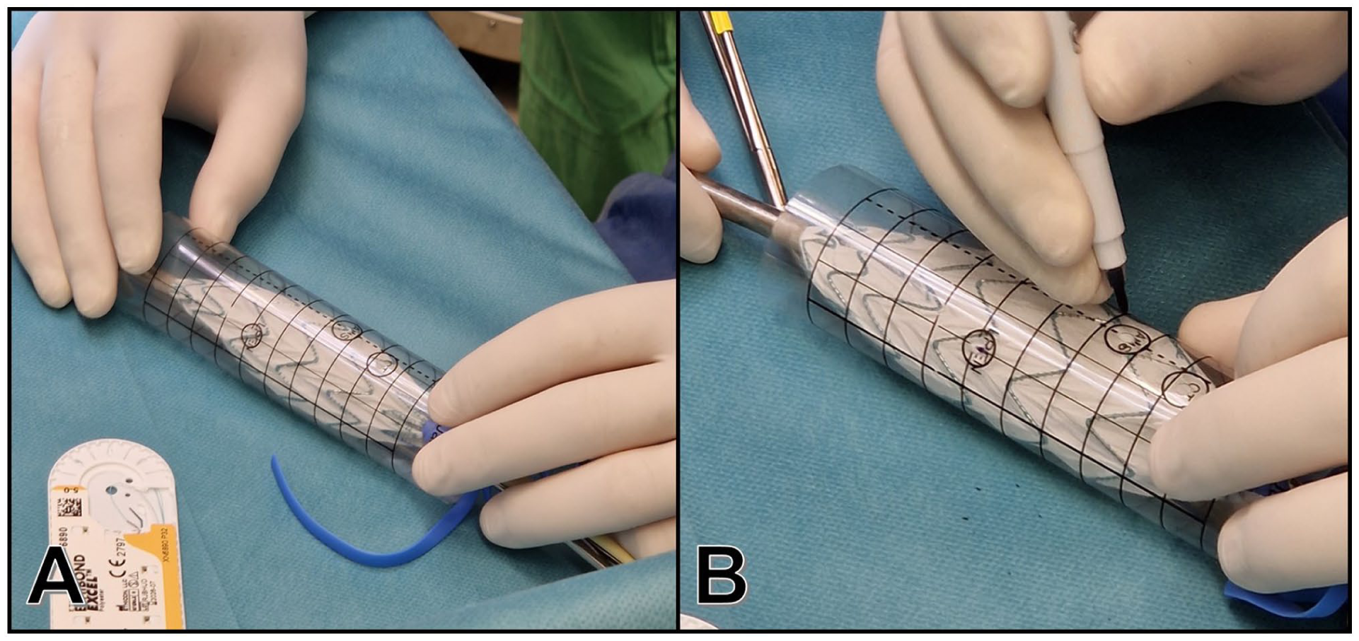
Steps of fenestration positioning with the punch card. (A) Semi-deployment of the endograft within the tube formed by the printed and sterilized transparent sheet. Strutless areas were identified for all fenestrations by rotating the device within the punch card. (B) Marking of the fenestrations through the holes of the punch card.
Manual Punch Card Creation
The process of punch card creation was performed as previously reported. 11 A proportionally scaled (1:1) fenestration diagram was created in a word processor (Word, Microsoft 365; Microsoft Corp, Redmond, Washington State) as a table with the following specifications: 12 columns and 20 rows, a table height of 10 cm, and a table width matching the circumference of the aortic endograft. The cells of the table were uniformly sized, with equal width and height. Each row corresponds to 5 mm, and each column corresponds to 3 hours, fenestrations were marked by a circle of the desired diameter, positioned at the planned vertical (distance to proximal edge) and horizontal (clock position) location. After completion of the patient-tailored punch card, it was saved as a portable document format (PDF) file.
Software-Assisted Punch Card Creation
A dedicated software tool (EndoDraft) was developed in Python 3.12.2 programming language to automate punch card creation and to visualize the planned template. After setting the desired graft diameter, baseline position, endograft type (tube or bifurcation), diameters, and positions of the intended fenestrations were entered manually and were positioned automatically on a 2D fenestration template as well as on a virtual 3D model, allowing for 3D visualization of the fenestrations (Figure 2). The software was used to generate a PDF file with a proportionally scaled fenestration diagram.
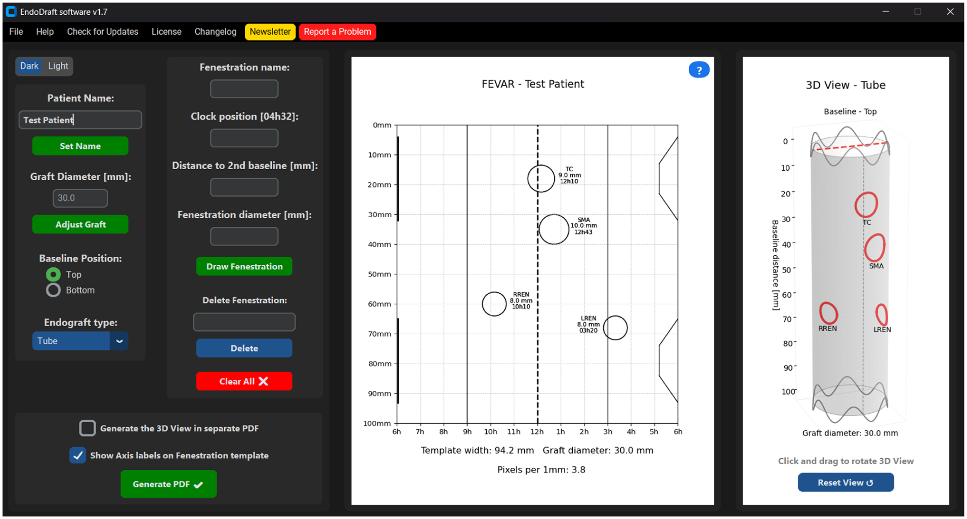
User interface of the EndoDraft software.
Background Operations in the Software
Resolution adjustment
Based on the specified graft size, the EndoDraft software uses the graft diameter to calculate the punch card template width. The software works on the X-axis of the template at a resolution of a minute, thus a total of 12 hours, accounting for 720 different values in minutes. The resolution of the X-axis depends on how these 720 different values are matched to the number of pixels on the screen according to the specified graft diameter. The number of pixels per millimeter may vary between different computer monitors; thus, the software checks the screen resolution before each calculation. This calculation is crucially important to accurately display the preview of the punch card template being made and later correctly generate the printable PDF:

where L is the template width in pixel, α is the number of pixels in 1 mm, D is the specified graft diameter in mm, and π is used to calculate the circumference. The axis labels and gradients move dynamically as the resolution changes.
Fenestration mapping
The placement of the fenestrations on the diagram is also based on the pixel distances, similar to setting the resolution. When the user specifies the clock position of the desired fenestration on the X-axis, the software looks up the index of the specified value in the 720 sized array. Based on the exact position and the pixel resolution of the 2 adjacent values of the X-axis, it places the circle marking the fenestration on the template:


where L is the template width in pixel, P is the fenestration position in pixel, λ is the offset needed based on the punch card template origin. The position on the longitudinal Y axis is calculated using the multiplication of the input and the number of pixels in 1 mm (α). The diameter of the generated fenestration circle is also calculated based on the user input and the number of pixels.
Mathematical 3D modeling
The 3D visualization module of the software represents a key element in providing an intuitive, spatial understanding of the fenestrated graft configuration. Currently, based on the user’s selection of endograft type, the software is capable of mathematically modeling both tube and bifurcated endografts in 3D. Mathematically, the stent graft can be modeled as a cylindrical surface generated by parametric equations. The cylinder has a radius equal to half of the graft diameter (R=D/2) and a height corresponding to the standard graft length (eg, 100 mm).
The coordinates of the cylinder are calculated as:


where Θ is the angular coordinate (0°-360°) around the cylinder, z is the longitudinal axis (baseline distance). Fenestrations are mapped onto the cylindrical surface by converting the user-specified clock position into an angular coordinate: each hour on the clock corresponds to 30° (360°/12), and each minute further refines this mapping by 0.5° per minute. Thus, a clock position (eg, 3h30) translates into an exact angle, from which the (X, Y) location is determined on the cylinder. Each fenestration is then visualized as a small, circular deformation on the cylindrical surface, based on its diameter. The fenestration’s local coordinates are generated using small perturbations (ΔΘ, Δz) around the central point, maintaining the correct geometric proportions.
Additionally, the baseline positioning can be dynamically adjusted either top-down (0 mm at the top of the graft) or bottom-up (0 mm at the bottom of the graft), depending on the surgical preference or anatomical requirements.
Supplementary sinusoidal curves are plotted near the graft edges to represent structural elements (supporting rings) and improve visual realism.
Overall, the 3D module provides a mathematically accurate, yet visually accessible model of the customized fenestrated stent graft, supporting precise surgical planning and design validation.
Creating a printable PDF
When the designed punch card is created in the software and the user clicks on the “Generate PDF” button, the program generates an A4 sized PDF containing the finished punch card template. Based on the preview design, the PDF is synchronized to the size, and the PDF creator redraws the punch card with perfect accuracy based on the information stored in the software. In addition, the software generates an information file in text file format (.txt) containing patient data and the punch card that has been created. When printing the punch card from the PDF, it is very important not to allow the printer to automatically resize the design, as this may distort the punch card dimensions.
Comparing Software-Assisted and Manual Planning
The EndoDraft software-assisted planning was compared with the manual technique in terms of time and accuracy of punch card creation. Each aortic plan was used for both manual and software-aided punch card creation, allowing direct, intra-individual comparisons. For the manual method, the start time was defined as the opening of a blank document, and the end time was the completion of PDF generation. For the EndoDraft software, the start was defined as the launch of the program, and the end was the completion of PDF generation. The errors were measured on manually created punch card templates using the Measuring Tool built into the Adobe Acrobat PDF software (Adobe Inc, Mountain View, California). To confirm the software’s accuracy, the distance of the given fenestration from the baseline on the software punch card template was measured and confirmed to exactly match the planned distance to proximal edge, while table width was measured and confirmed to precisely match the circumference of the chosen diameter of the device. Thus, the software’s PDF output was considered as free of inaccuracies and used as the reference for further evaluations, given that the only potential for errors while using the software is mistyping during data input.
In each case, the deviation of the given fenestration in the X and Y axes from the reference was measured to obtain the deviations due to human error. For the clock position (X-axis), we first measured the distance of the given fenestration on the software punch card from a specific point, which was usually the center at 12 o’clock. This distance was then used as a reference against which to compare the distance of that same fenestration from the center point on the manually drawn punch card. For the distances from the baseline (Y axis), the distances were measured in the same manner with the baseline being the reference line. The same steps were repeated for all fenestrations on manually and software-generated punch cards. Longitudinal imprecision was expressed as mms of difference found along the Y axis, while circumferential error was defined as mms of the difference found along the X-axis.
Statistical Analysis
The measured parameters are reported as mean ± standard deviation (SD), and categorical variables are presented as numbers and percentages (n, %). The Shapiro-Wilk test was used to confirm the normality of the data. T-tests and paired T-tests were used for comparisons between total manual technique time and total software usage time. p-value≤0.05 was considered significant. Statistical analysis was performed using Stata (18.0, StataCorp LLC, College Station, Texas) software.
Results
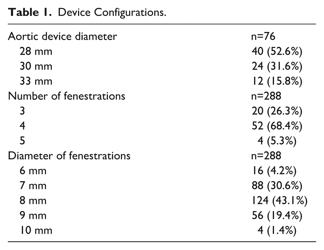
Based on the fenestration data of the same 38 patients, a total of 76 punch cards were created, 38 in the manual and 38 in the software-assisted group. A total of 288 fenestrations were made during the tests. The configurations of the planned devices are shown in Table 1.
Device Configurations.
Preparation time was 233.0 ± 40.3 seconds for the manual group, whereas 63.2 ± 21.5 seconds for the software-aided group (p<0.001, Figure 3).
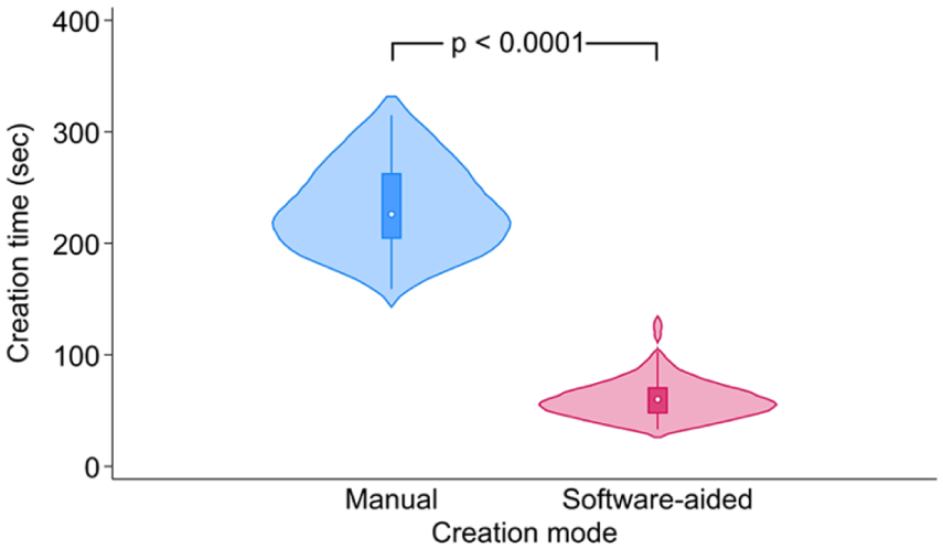
A violin plot showing the creation time of the punch card in the manual and in the software-aided group.
Longitudinal imprecision of the manual punch card was 0.8 ± 0.6 mm for the celiac axis (CA), 1.0 ± 0.6 mm for the superior mesenteric artery (SMA), 0.8 ± 0.5 mm for the right renal artery (RRen), and 1.0 ± 0.6 mm for the left renal artery (LRen). Circumferential errors of the same fenestrations were 0.4 ± 0.4 mm for the CA, 0.4 ± 0.4 mm for the SMA, 0.6 ± 0.5 for the RRen, and 0.5 ± 0.4 mm for the LRen (Figure 4).
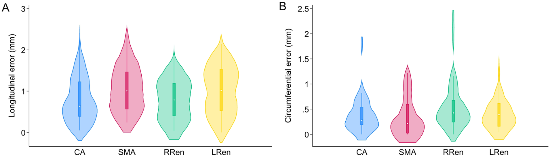
A violin plots showing the longitudinal (A) and circumferential (B) errors of the fenestrations of the manual technique (CA, celiac axis; SMA, superior mesenteric artery; RRen, right renal artery; LRen, left renal artery) compared to the software-based reference.
To evaluate the learning curve of each technique, the initial and terminal 3-3 cases of both observers were evaluated as subgroups in both arms. For the manual technique, initial cases needed 246.9 ± 48.6 seconds to complete, while terminal cases were performed within 215.2 ± 23.7 seconds (p=0.08). For the software-aided cases, initial subgroup was performed within 77.8 ± 29.4 seconds, whereas terminal cases were completed within 55.8 ± 18.5 seconds (p=0.15).
Discussion
This benchtop investigation demonstrates the superiority of software-assisted punch card generation with the purpose-built EndoDraft application over manual fenestration positioning during PMEG FEVAR. The software enables markedly faster template creation, whereas the minor inaccuracies inherent to manual techniques—although measurable—are of uncertain clinical significance.
Accurate fenestration positioning is critical in PMEG procedures. The relative spacing of fenestrations must be preserved to prevent circumferential mismatch and consequent “shuttering” of the target ostium. Operators also strive to locate fenestrations in strut-free graft segments to avoid struts crossing the fenestration, which could compromise long-term durability. Manual measurement of arc lengths remains the most common approach, but it becomes cumbersome in multi-vessel configurations. To enhance precision and efficiency, some practitioners employ templates ranging from simple sterile-package foils marked intraoperatively to sophisticated 3D-printed cylindrical or anatomical models, which improve accuracy but add workflow complexity.6,7,9
The punch card technique was devised to retain the precision of a 3D model without the burden of 3D printing. 11 Álvarez Marcos et al 8 reported a comparable smart template incorporating graft-strut design, yet both approaches require manual marking. To expedite production and reduce human error, dedicated software was developed. Automated fenestration mapping substantially accelerates template creation while maintaining high positional accuracy. Although graft-strut data are not embedded, the printed template can be circumferentially adjusted to avoid struts, offering practical flexibility across endograft types without device-specific strut or dimension data.
Despite advances in artificial intelligence and machine learning, the CMD workflow has remained largely unchanged over 2 decades and has yet to integrate such technologies. Automated FEVAR planning options—particularly for PMEG—remain scarce and are not publicly accessible.10,12
Rapid preparation is especially valuable in urgent PMEG. In such settings, a punch card may be pre-sterilized in various sizes without pre-punched fenestrations; holes can then be cut at the table. Although this expedites use, positional accuracy is reduced: circumferential deviations are typically sub-millimetric, and longitudinal errors are generally <2 mm. Given the common 8 mm fenestration diameter, such offsets seldom produce clinically meaningful shuttering.
The software-assisted method has a short learning curve and permits swift attainment of proficiency. The principal potential source of error is data-entry mistyping, which could be avoided through direct transfer of fenestration coordinates from planning software. However, current FEVAR planning platforms export only JPEG or PDF files, which are unsuitable for numerical data exchange. With the expansion of structured reporting and registry participation, the need for standardized numerical export is increasing.
Since its introduction, the EndoDraft software has been incorporated into routine clinical practice. The laser-printed foil templates, combined with integrated 3D visualization, enhance preoperative planning by providing a clear spatial representation of fenestration locations, thereby supporting accuracy and confidence during graft modification.
Software Availability
The software is free to be downloaded from an online repository. 13 Redistribution, modification, or commercial use of the software is strictly prohibited without prior written permission from the author. The software is provided “as is,” without warranty of any kind, and is distributed as a complied executable (.exe) file only, with no source code provided.
Disclaimer
While this software has been tested and works as intended under controlled conditions, the authors cannot guarantee identical results across all platforms, printers, and settings. Users are strongly advised to perform a test run before any real-life application. Specifically, it is recommended to generate a test punch card using the software and print it with the intended hardware setup. Careful measurements to be performed on the printed template, ensuring that no distortion (eg, scaling or warping) has occurred during printing.
The authors take no responsibility for any inaccuracies or undesired outcomes arising from environmental variables, printer settings, or other external factors beyond the software itself. This software tool is not approved by any authorities for clinical use.
Limitations
The tests were conducted using the software output as the reference standard. To verify the accuracy of the software-generated results, multiple iterations of testing were performed. Afterward, the software-generated PDF was deemed free of any relevant inaccuracies.
Conclusions
The software-assisted design of the punch card is associated with a higher degree of precision and a vast improvement in speed compared to the manual technique during physician-modified endograft planning for the endovascular treatment of complex abdominal aortic aneurysms. The purpose-built EndoDraft software is freely available through an online repository, offering a more streamlined workflow. 13
Footnotes
Acknowledgements
Not applicable.
Ethical Approval
Study protocol was approved by the local ethics committee (129/2024).
Informed Consent
Informed consent to participate has been waived by the relevant Ethics Committee.
Funding
The authors disclosed receipt of the following financial support for the research, authorship, and/or publication of this article: Bendegúz Juhos was supported by the 2024-2.1.2-EKÖP-KDP-2024-00002 University Research Scholarship Programme of the Ministry for Culture and Innovation from the source of the National Research, Development and Innovation Fund of Hungary. Dr. Csaba Csobay-Novák was supported by a grant from the National Research, Development and Innovation Office (NKFIH) of Hungary (STARTING 152421) and by the János Bolyai Research Scholarship of the Hungarian Academy of Sciences.
Declaration of Conflicting Interests
The authors declared the following potential conflicts of interest with respect to the research, authorship, and/or publication of this article: CCN is a trainer, speaker, and proctor for Cook Medical, Gore Medical, and Medtronic.
Data Availability Statement
The data supporting the findings of this study are available from the authors upon reasonable request.