
Abstract
The paper investigates how the Cr/C ratio influences microstructure and corrosion behaviour of hypoeutectic high-chromium cast irons (HCCIs) in 3.5 wt% NaCl, 0.5 M NaOH and 0.5 M H2SO4. Three alloys; P1 (Cr/C = 12.13, 26.3% carbides), P2 (8.62, 37.3%) and P3 (8.06, 42.9%) were evaluated based on carbide size, morphology and distribution. Open-circuit potential and potentiodynamic polarisation corrosion tests were performed on the samples. In NaCl, P3 showed the most severe corrosion due to micro-galvanic effects from coarse, interconnected carbides and limited Cr available for passivation. In NaOH, P1 corroded the most due to rapid carbide dissolution and insufficient sustained Cr release for passive film growth. In H2SO4, P3 suffered the greatest attack, driven by galvanic interactions and unstable film formation. Heat treatment refined carbide distribution and promoted secondary carbide precipitation. These changes improved corrosion resistance in neutral media but increased it in acidic and alkaline. These results show that Cr/C ratio and carbide control are key to optimising HCCI corrosion resistance.
Introduction
High-chromium cast irons (HCCIs) are a class of wear-resistant materials extensively used in applications where components are exposed to both wear and corrosive media. The HCCI's superior performance stems from a microstructure composed of a hard, chromium-rich carbide phase embedded in an austenitic or martensitic matrix. This combination offers excellent resistance to abrasion, erosion and to some extent, corrosion.1–5 Applications such as sugarcane crushing rolls, impeller components, screw barrels, coal crusher hammers and slurry pump parts regularly rely on HCCI for its durability under aggressive service conditions.1–7 However, despite their wide industrial use, the corrosion behaviour of HCCIs, particularly those used as hardfacing alloys, remains underexplored, especially in harsh acidic environments such as those found in the chemical, mining and marine sectors.1–4 In such environments, corrosion typically occurs through galvanic interaction between the chromium-depleted austenite matrix and chromium-rich carbides. The matrix often acts as the anodic site, while the carbides serve as cathodes, promoting localised corrosion, especially at the carbide–matrix interfaces.7,8 This behaviour has been widely observed in both acidic and neutral media, where preferential dissolution of the matrix occurs due to potential differences between the phases.8,9
The type, size and distribution of carbides significantly influence corrosion resistance.9–11 As the chromium content increases, the type of eutectic carbides changes from M3C to M7C3, with M7C3 being harder and more corrosion-resistant.12,13 For instance, alloys containing above 10% Cr typically develop discontinuous M7C3 carbides with hardness levels of up to HV 1800, offering greater protection under corrosive conditions. Yet, high carbide volume fractions, if unevenly distributed or forming complex networks, can promote galvanic corrosion, particularly when chromium segregation or depletion at the matrix interface is present.12,14 Corrosion in HCCIs is highly environment specific. In acidic environments, such as 0.5 M H2SO4, corrosion rates are often high due to continuous passive film breakdown by aggressive sulphate ions. Studies have shown that hydrogen evolution in acidic solutions interferes with passive layer formation, leading to more active dissolution of the matrix.9,10 Increasing carbon content, which promotes carbide formation, may help reduce corrosion by decreasing the matrix volume available for attack.9,10 Conversely, in neutral environments like seawater, the primary form of degradation is micro-galvanic corrosion, where corrosion typically initiates in the chromium-depleted zones surrounding the carbides.5–8 In alkaline environments, such as NaOH solutions, carbides themselves are preferentially attacked due to their lower self-corrosion potential relative to the matrix, and the corrosion resistance improves gradually as chromium is released and a passive film is formed.6,7
Understanding the microstructural effects, including carbide volume, phase distribution, chromium content and heat treatment on corrosion behaviour is essential for improving alloy performance across different environments. Heat treatment can refine carbide morphology, reduce matrix segregation and influence secondary carbide precipitation, all of which affect corrosion resistance in different ways depending on the corrosive medium.11,15 Given the diverse service conditions in which HCCIs are deployed, this study aims to examine the corrosion behaviour of three HCCIs; P1 (Cr/C = 12.13, 26.3% carbides), P2 (8.62, 37.3%) and P3 (8.06, 42.9%) in acidic, neutral and alkaline environments. Special focus is placed on understanding how microstructural features influence the dominant corrosion mechanisms in each medium, and how these relate to galvanic interactions, passive film stability and chromium availability within the matrix.
Materials and methods
Materials
Casting
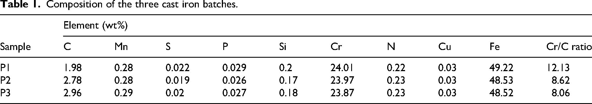
The HCCI samples were designed with specific Cr/C ratios to study the effect of composition on microstructural evolution and corrosion behaviour. Chromite sand mixed with bentonite and water was used to prepare moulds, which were compacted in wooden patterns and left to harden before casting. Three alloy batches were produced using a 40 kg induction furnace, where iron scrap, iron remelt, Fe-Cr, Fe-Mo and sascurb were melted at approximately 1500°C. The molten metal was then poured into the prepared moulds to form ingots, with the composition adjusted after each pour to achieve the next Cr/C ratio. Chromium was kept constant to isolate its influence and ensure that any observed changes in microstructure and corrosion response were primarily due to variations in carbon content. Small increases in carbon were introduced to promote differences in carbide volume, morphology and distribution. The final alloy compositions are listed in Table 1.
Composition of the three cast iron batches.
Methods
Sample preparation
The HCCI samples are cut into 10
Heat treatment
Heat treatment was carried out on three HCCI samples from each composition using a Bohler steel muffle furnace. The procedure was adapted from China Patent No. CN102899469B (2013), selected for its reported ability to improve toughness while preserving corrosion resistance in HCCIs. The process involved a multi-stage cycle comprising an initial quench at 1050°C for 3 h, followed by air cooling to room temperature. This was succeeded by high-temperature tempering at 700°C for 2 h and air cooling. A secondary quenching stage was then conducted at 1050°C for 3 h, followed by air cooling, after which the samples underwent successive low-temperature tempering treatments at 450°C for 1.5 h each, with air cooling to room temperature between cycles. The aim was to refine the microstructure by transforming the continuous plate-like carbides into thicker, more spherical shapes, and to promote more uniform diffusion of elements within the matrix. This treatment aimed to reduce chromium segregation, refine grain boundaries and homogenise the carbide distribution. These changes were expected to improve not only mechanical toughness but also corrosion resistance, particularly in environments prone to localised attack.
Corrosion testing
Corrosion behaviour of the HCCI samples was evaluated using electrochemical techniques in three corrosive environments: 3.5 wt% NaCl, 0.5 M NaOH and 0.5 M H₂SO₄ solutions. The open-circuit potential (OCP) and potentiodynamic polarisation tests were carried out using a standard three-electrode electrochemical cell connected to a Gamry® potentiostat.The mounted and polished HCCI sample, with an exposed surface area of 0.286 cm², was used as the working electrode. A platinum wire served as the counter electrode, and a saturated Ag/AgCl electrode was used as the reference electrode. The test began with OCP which was conducted for 3600 s, followed by potentiodynamic polarisation scan ranging from −0.5 to 1.0 V at a standard scan rate of 0.1667 mV/s at room temperature. The corrosion potential (Ecorr), corrosion current density (Icorr) and corrosion rates (CR) were determined according to ASTM G59-97 standards.
Microstructural characterisation
The microstructural characteristics of the HCCI samples were examined using scanning electron microscopy (SEM), energy-dispersive spectroscopy (EDS) and X-ray diffraction (XRD). Specimens were prepared from the as-cast, heat-treated and corroded samples. The microstructure was analysed using a Carl Zeiss SmartSEM SIGMA 03-39 scanning electron microscope at magnifications ranging from 200× to 5000× using backscattered electron (BSE) imaging. Compositional analysis was carried out using EDS system with INCA software for spot and area scans. Phase identification of the HCCI samples was determined by XRD using a Co Kα radiation source (λ = 1.78899 Å) operated at 30 kV and 25 mA, with scans recorded over a 2θ range of 20°–120° at room temperature.
Results
Microstructure characterisation of as-cast and heat-treated HCCIs
The microstructures of as-cast HCCIs are generally characterised by a matrix of austenite or its transformation products such as ferrite, along with a network of primary and eutectic M7C3 carbides.8–10 Figure 1(a)–(c) shows the microstructures of samples P1, P2 and P3 after casting. Table 2 summarises the average primary carbide sizes, their variances and total carbide volume fractions. Sample P1, with a Cr/C ratio of 12.13 and low carbon content (1.98%), displays a dendritic austenitic matrix with fine, needle-like M7C3 carbides spaced widely apart. The carbide volume is ∼26.26%, with an average primary carbide size of 143 µm and low size variation, consistent with observations made by Guo et al. 16 and Li et al., 17 that reported lower carbon content leads to finer carbide formation and wider dendritic spacing. Sample P2 (Cr/C = 8.62) shows a more interconnected carbide network with hexagonal or rounded M7C3 carbides. The measured carbide volume is ∼37.27%, with a larger average carbide size of 217 µm, but still relatively uniform. Karantzalis et al. 18 and Guitar et al. 19 also found that moderate carbon increases carbide coarsening and promotes more continuous carbide networks. Sample P3 (Cr/C = 8.06) has the highest carbide volume (∼42.90%) and features coarse, irregular and continuous carbide networks with an average size of 1431 µm and high variation in carbide size, indicating uneven distribution. Wiengmoon et al. 20 reported that high carbon levels favour large, interconnected carbides, which reduce matrix continuity. EDS analysis (Supplementary Figure 1(a)–(f)) confirms that the matrix is mainly Fe and Cr, while the carbides are Cr-rich, typical of M₇C₃ carbides, aligning with findings by Scandian et al. 21 and Purevdorj et al. 22
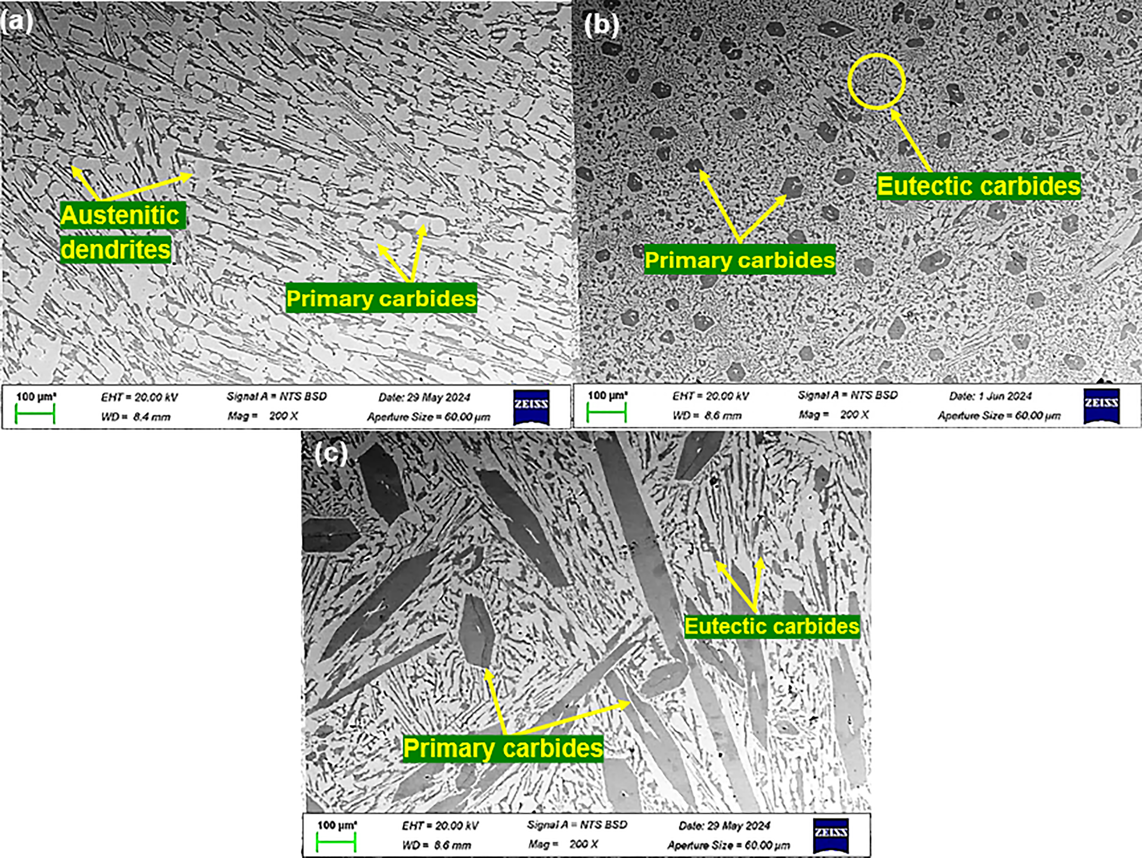
SEM image showing the microstructure of P1 (a), P2 (b) and P3 (c). Light phase is the matrix; dark phase is the carbide.
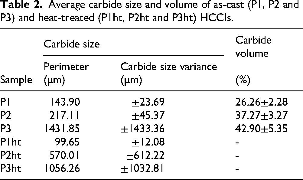
Average carbide size and volume of as-cast (P1, P2 and P3) and heat-treated (P1ht, P2ht and P3ht) HCCIs.
The bulk chemical composition (Table 1) in all three samples is classified as hypoeutectic alloys which is expected to initially precipitate only primary austenite dendrites, whereas the microstructures of P2 and P3 exhibit coarse M7C3 phases that appear similar to primary carbides (Figures 1 and 2). This stems from non-equilibrium solidification inherent to the casting process. Due to rapid cooling, compositional segregation of chromium and carbon heavily enriches the liquid phase between the growing austenite dendrites. 23 This local enrichment pushes the liquid composition into the hypereutectic field, causing the M7C3 phase to nucleate locally and grow large before the overall eutectic reaction begins. 24 Thus, these phases are classified as early-forming M7C3 eutectic carbides, whose coarse morphology is a consequence of local chemical conditions.
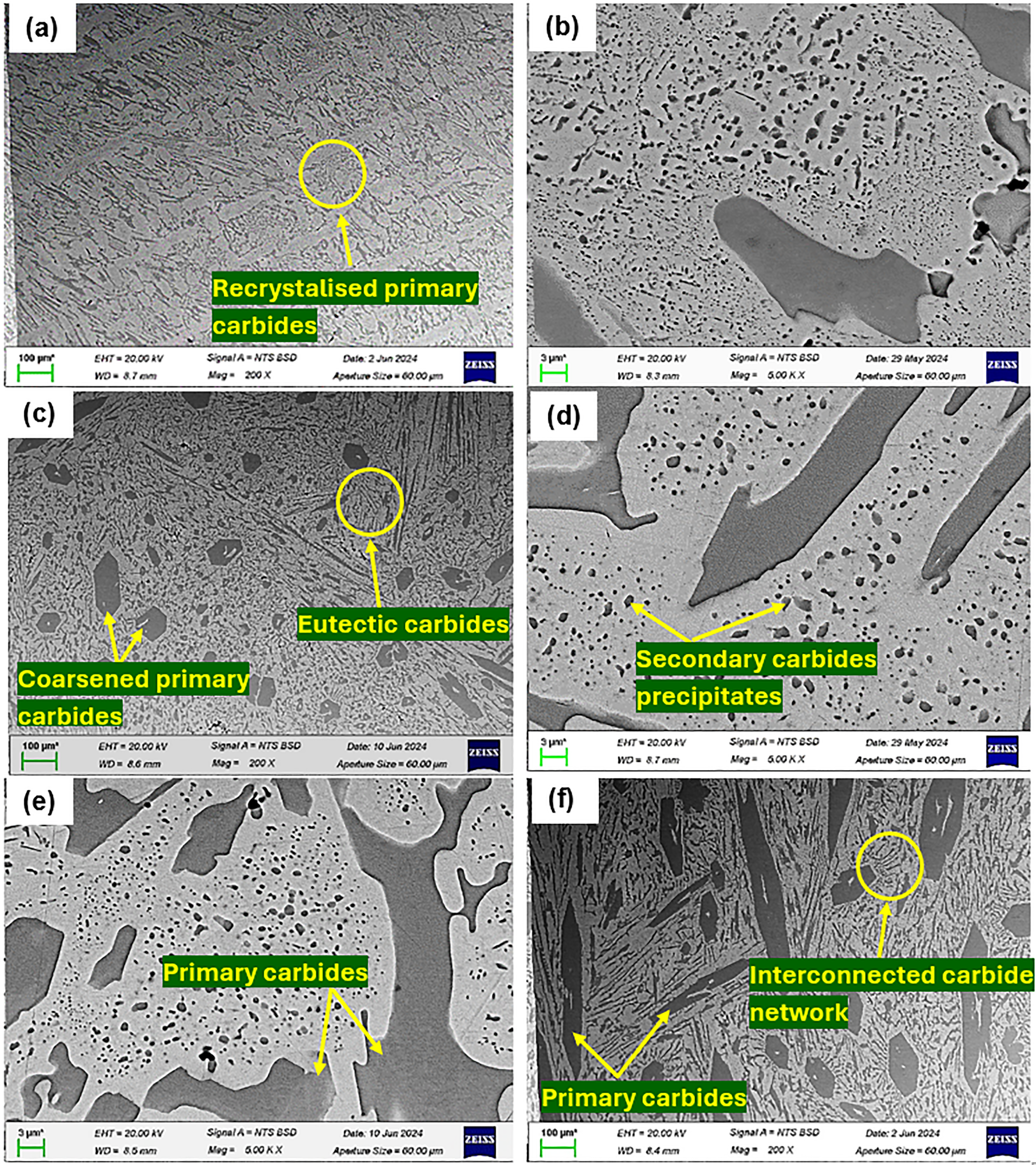
SEM images of microstructures after heat-treatment for P1ht (a), P2ht (c) and P3ht (e). High-magnification SEM images showing precipitates in the matrix of P1ht (b), P2ht (d) and P3ht (f).
Figure 2(a), (c) and (e) shows significant changes in the microstructure of samples P1, P2 and P3 after heat treatment. On one hand, sample P1ht exhibited a refined and more homogeneous microstructure, with smaller, more evenly distributed M₇C₃ carbides compared to the as-cast condition. Specifically, the average primary carbide size in P1 decreased from 143.90 µm (as-cast) to 99.65 µm (heat-treated), and the carbide size variance decreased to ±12.08 µm, indicating effective grain refinement and improved uniformity. Sample P2ht, on the other, shows coarsening of primary carbides: the average size increased from 217.11 µm (as-cast) to 570.01 µm (heat-treated), and size variance increased to ±612.22 µm. Despite this coarsening, the matrix remains relatively uniform, and eutectic carbides continue to cover much of the matrix surface, suggesting that overall homogeneity was retained. Sample P3ht retains its coarse carbides, but they appear more blocky and less continuous than in as-cast P3 where the average primary carbide size decreased from 1431.85 to 1056.26 µm, and the size variance decreased from ±1433.36 to ±1032.81 µm. As a result, the carbide network became more evenly distributed, reducing the directional alignment seen before heat treatment. At higher magnification (Figure 2(b), (d) and (f)), secondary M7C3 carbides are observed within the matrix. These smaller, rounded precipitates indicate additional chromium and carbon redistribution during heat treatment.
The XRD patterns of the as-cast and heat-treated HCCI samples are shown in Figure 3(a)–(c). Peaks for the as-cast HCCI samples are austenite and M7C3 phases, with P1 showing stronger austenite peaks and P3 stronger carbide peaks. The weak or missing austenite peak near 2θ ≈ 50° in the P1 as-cast trace is most likely an experimental and microstructural effect rather than evidence for no austenite. Local low diffracting volume (due to interdendritic segregation and carbide concentration), partial peak overlap with strong M7C3 peaks, peak broadening from microstrain or small crystallite size and preferred orientation can all reduce the intensity of a single peak while other austenite peaks remain detectable. 25 The presence of an austenitic matrix in P1 is supported by the remaining XRD peaks and by SEM-EDS maps (Supplementary Figure 1) shows an Fe-rich matrix consistent with austenite. These results agree with previous work by Li et al. 17 and Touhami et al., 26 confirming a shift from fine, dispersed carbides in P1 to coarse, interconnected carbides in P3. XRD patterns of the heat-treated HCCI samples also confirm the presence of both austenite and M₇C₃ carbides, with sharper and more intense peaks in the heat-treated samples, reflecting this increased carbide refinement.
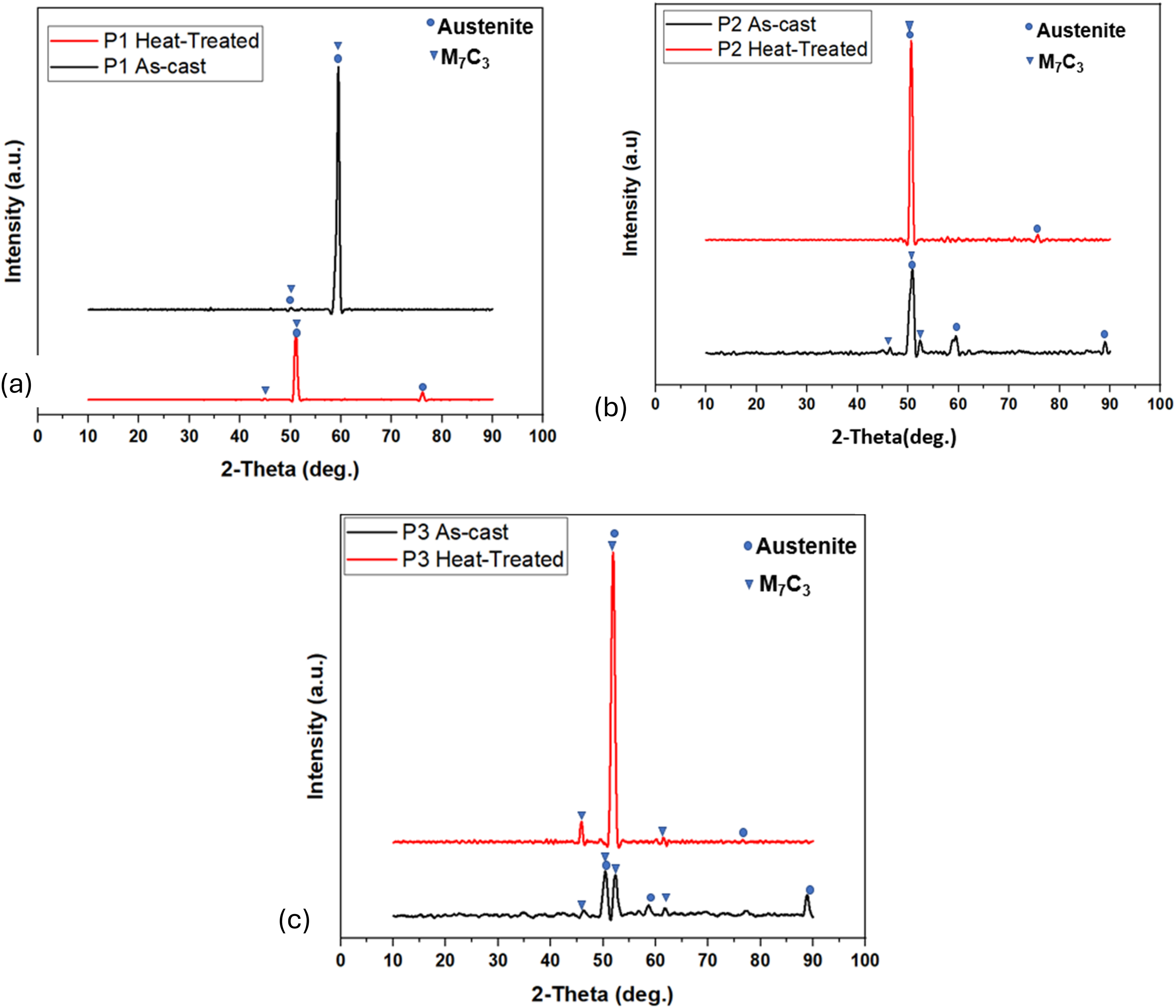
XRD patterns for as-cast and heat-treated HCCI sample P1 and P1ht (a), P2 and P2ht (b), P3 and P3ht (c).
The XRD patterns show austenite and M7C3 carbides after heat treatment, matching the SEM and EDS results. This outcome follows from the multistage heat treatment and the alloy chemistry. Austenisation at 1050°C creates a supersaturated austenite phase 27 and because the samples were air cooled between stages rather than rapidly quenched, not all austenite transformed to martensite. 28 The high chromium and carbon contents also stabilise austenite. 29 Repeated tempering and secondary carbide precipitation redistribute carbon and chromium in the matrix, removing carbon from some regions and leaving others relatively enriched, so measurable retained austenite can remain.30,31 The heat treatment also drives carbide dissolution and reprecipitation, with M23C6 possibly transforming into M₇C₃ during tempering.31,32 Finally, XRD reports bulk phases and cannot by itself determine whether individual carbides seen in SEM are primary, proeutectic or secondary. 21
Corrosion behaviour of as-cast HCCI alloys
NaCl solution
The OCP and potentiodynamic polarisation curves of the as-cast HCCI alloys in 3.5 wt% NaCl solution are shown in Figure 4. The OCP curve showed a common trend of an initial rapid rise, followed by a decline and stabilisation (Figure 4(a)). This pattern reflects the initial formation of a passive film on the alloy surface, which is then partially disrupted before reaching a stable condition. A higher and more stable OCP value indicates a more corrosion-resistant surface due to a stronger passive layer.33–36 Fluctuations in the OCP curves, particularly in P2 and P3, suggest localised breakdown and repassivation of the passive film, likely due to chloride ion penetration. The overall trend shows that alloys with finer, more uniform microstructures tend to maintain more stable OCPs, implying better corrosion resistance.33–36 The potentiodynamic polarisation curves (Figure 4(b)) support the OCP results. All samples showed active dissolution after reaching their corrosion potential. Samples P1 and P2 had lower corrosion current densities and corrosion rates than P3 (Table 3), meaning they were more resistant to corrosion.
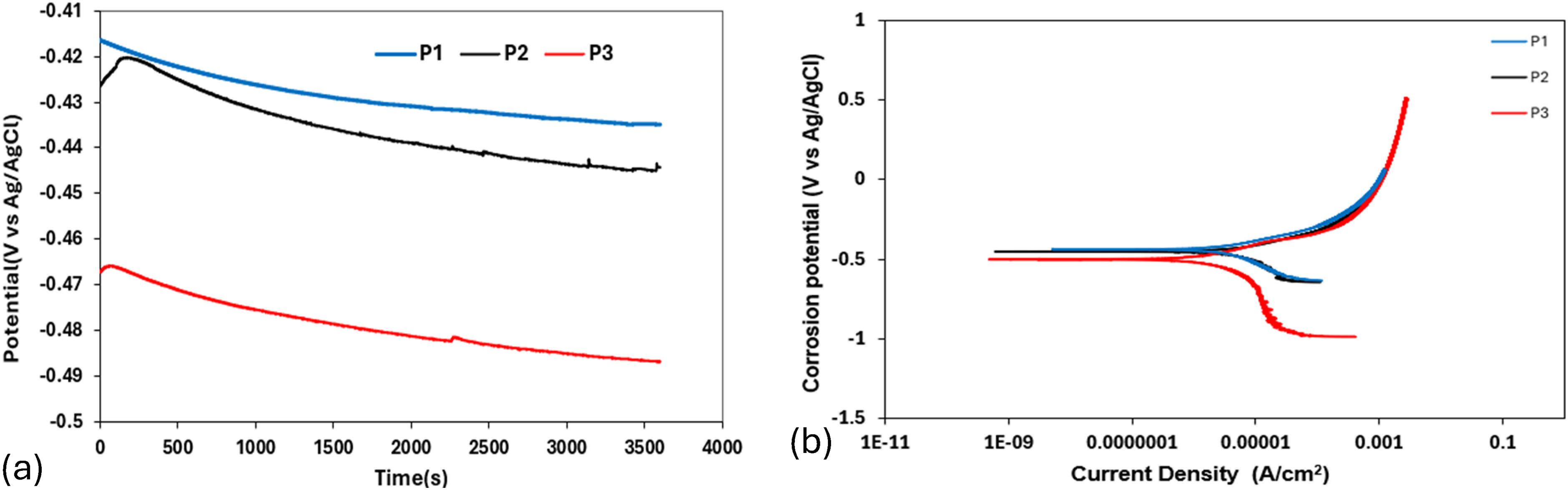
(a) OCP and (b) potentiodynamic polarisation curve of as-cast HCCI alloys in 3.5 wt% NaCl solution.
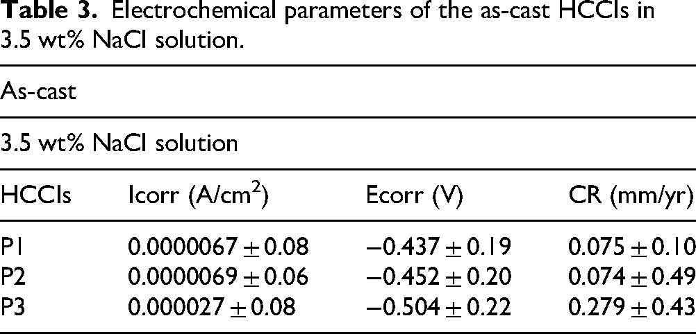
Electrochemical parameters of the as-cast HCCIs in 3.5 wt% NaCl solution.
The SEM images after corrosion in 3.5 wt% NaCl show that P1 and P2 had mostly intact surfaces with only minor signs of corrosion (Figure 5(a) and (b)). There was minimal pitting, and the carbide–matrix interfaces remained largely undamaged. This matches their similar corrosion rates shown in Table 3. The fine M₇C₃ carbides in both samples stayed well-embedded in the matrix, with no deep grooves or large voids. Their small size and even distribution likely helped form a stable passive film that protected the surface. In contrast, P3 showed more corrosion damage. The matrix had partially dissolved, especially around the large primary carbides, leading to deeper grooves and signs of carbide detachment (Figure 5(c)). This is consistent with its slightly higher corrosion rate. The surface looked rougher, and material loss was more obvious, suggesting that the matrix was more affected than the carbides in this sample. Overall, all three samples experienced corrosion, but P1 and P2 were better protected, while P3 showed a more severe surface attack. These results agree with the potentiodynamic polarisation curves (Figure 4(b)), which also showed similar corrosion behaviour for P1 and P2, and slightly higher corrosion susceptibility for P3.
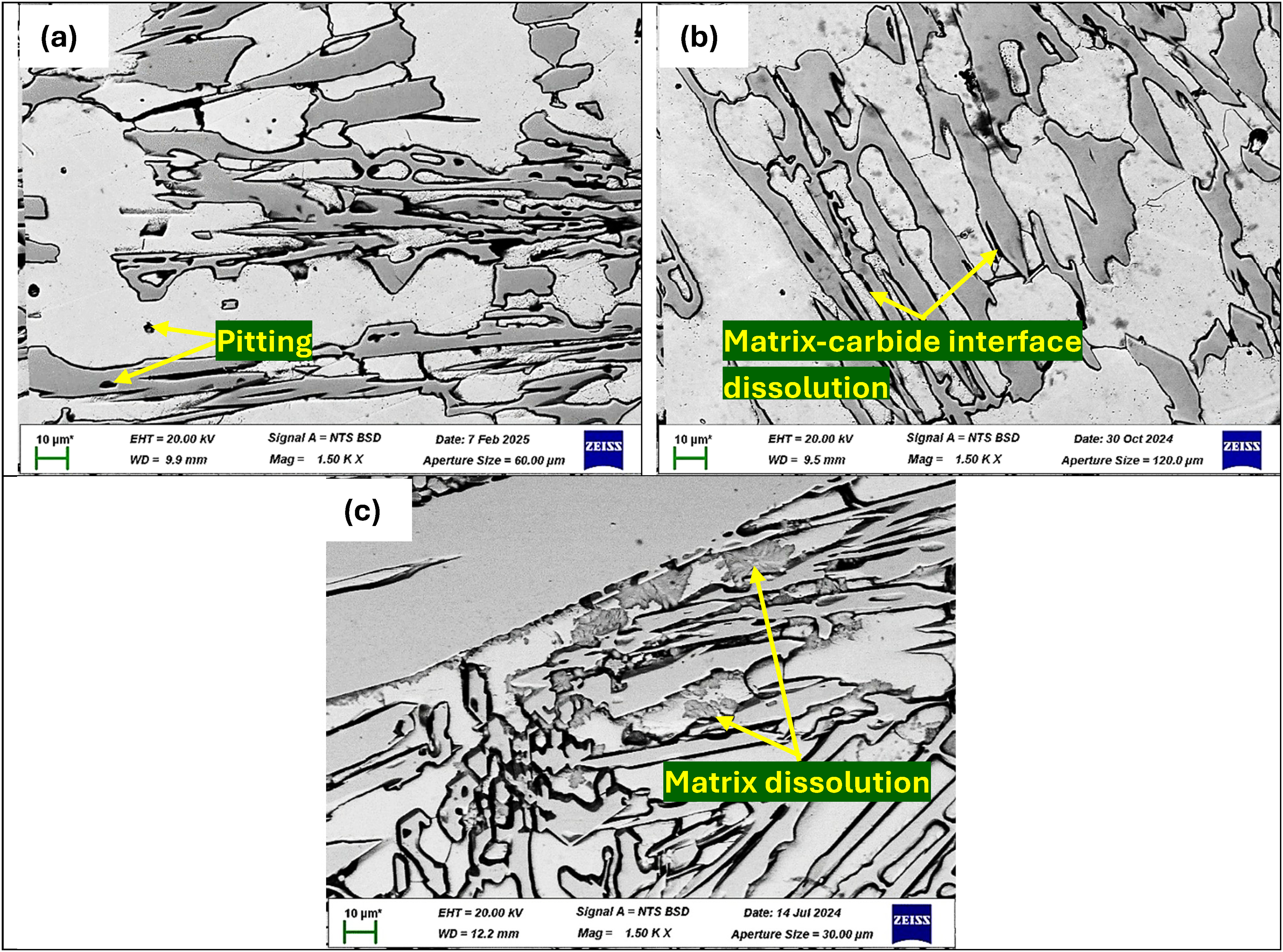
BSE-SEM images of as-cast P1 (a) P2 (b) and P3 (c) after electrochemical testing in 3.5 wt.% NaCl solution.
NaOH solution
The OCP and potentiodynamic polarisation curves of the as-cast HCCI alloys in 0.5 M NaOH solution are shown in Figure 6. The OCP curves showed that P1 maintained the highest and most stable potential, indicating early and effective passive layer formation (Figure 6(a)). Samples P2 and P3 started at the lower potential but steadily improved over time, to reach a more stable and high potential. All as-cast HCCI samples showed smooth OCP curves (Figure 6(a)) without any fluctuations, suggesting a slow but steady development of passivation. Stable OCP has been attributed to the building of compact and protective oxide films on alloy surfaces.33,37 The potentiodynamic polarisation curves (Figure 6(b)) supported the OCP findings and confirmed the trends observed in 0.5 M NaOH solution (Table 4). Sample P1 displayed the most positive corrosion potential and the highest corrosion rate, followed by P3, while P2 exhibited the lowest corrosion rate. All samples showed corrosion behaviour of active dissolution, passivation and transpassivation and very low Icorr values indicating slow overall corrosion.
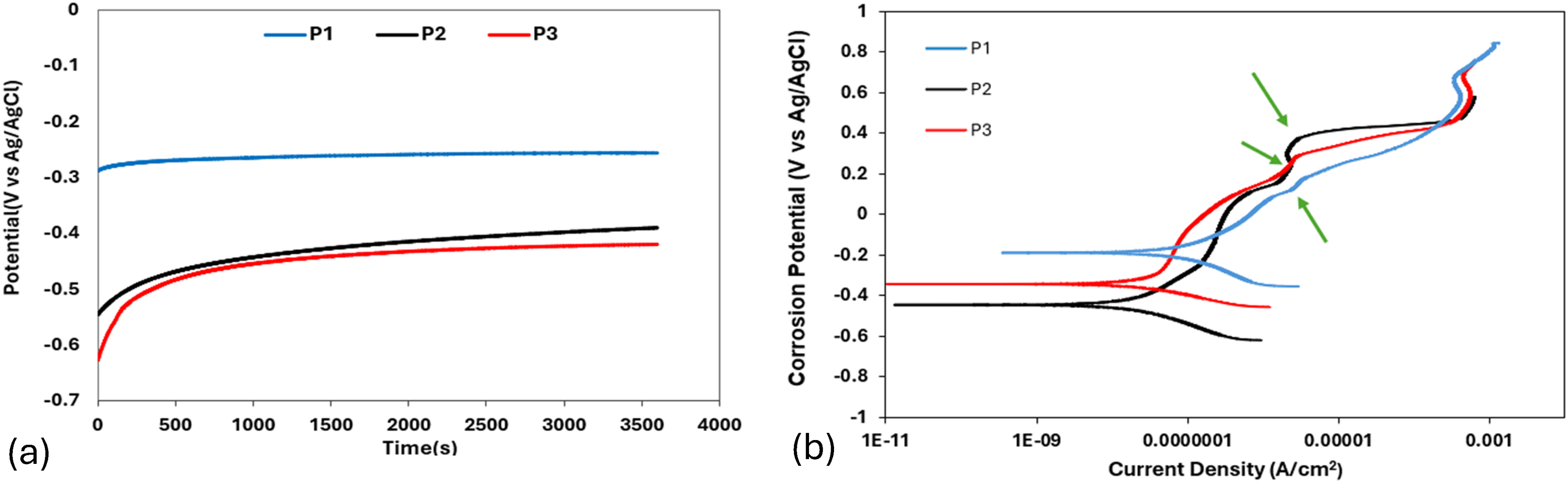
(a) OCP and (b) potentiodynamic polarisation curve of as-cast HCCI alloys in 0.5 M NaOH solution.
Electrochemical parameters of the as-cast HCCI alloys in 0.5 M NaOH solution.
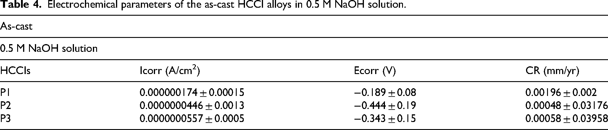
In the case of P1, the passive region was the most pronounced with elevated current density during passivation, implying robust oxide film formation despite slight instability caused by uneven carbide dissolution. This accounts for its largest shift towards higher current density on the polarisation curve. For P2, despite its lower corrosion potential and greater initial reactivity, the current density dropped to its lowest level once passivation commenced, indicating reduced corrosion in the passive state. However, the passive region displayed frequent fluctuations pointing to intermittent film breakdown and repair. P3 exhibited intermediate behaviour with corrosion and passivation characteristics between those of P1 and P2, and its passive region was more stable than that of P2 but less effective than that of P1.
The SEM images in Figure 7 show that corrosion in 0.5 M NaOH mainly affected the carbides, while the matrix remained mostly intact across all samples. Sample P1, the microstructure stayed well-preserved with only narrow corrosion channels along the carbide boundaries and shallow pits forming where carbides were located (Figure 7(a)). This matches the stable OCP, and strong passive film formation seen in the polarisation curve, suggesting that carbide dissolution contributed to a protective layer that shielded the matrix. Sample P2 showed clear and deeper dissolution of carbides, particularly the larger ones, while the matrix surface stayed largely unaffected (Figure 7(b)).
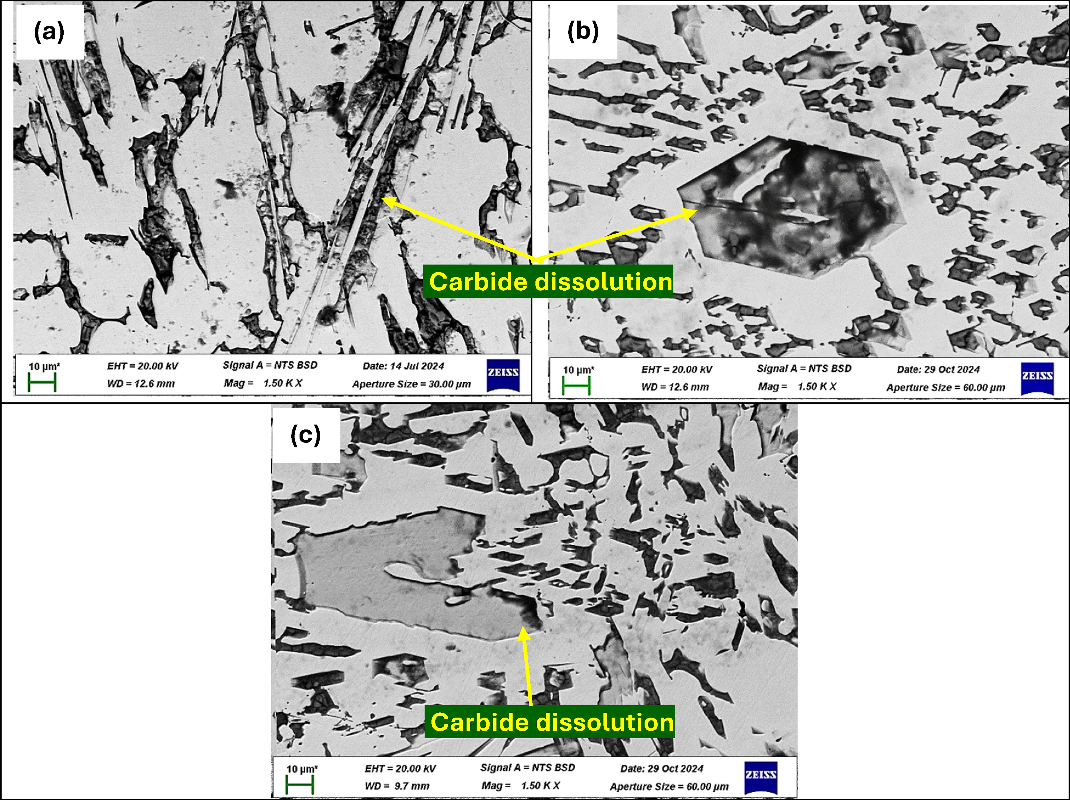
BSE-SEM images of surface morphology of as-cast P1 (a) P2 (b) and P3 (c) after electrochemical testing in 0.5 M NaOH solution.
This explains the low corrosion current and unstable passive region seen in the polarisation curve, where the film formed but broke down repeatedly. The uneven dissolution created cavities that left the matrix raised above the corroded areas, supporting the fluctuations observed in the OCP. Sample P3 also showed preferential attack on the larger primary carbides, with no major damage to the matrix (Figure 7(c)). The extent of carbide corrosion was moderate, which aligns with the polarisation and OCP results showing intermediate corrosion potential and more consistent passivation than P2, though not as effective as P1. Overall, the SEM images confirm that corrosion occurred mainly in the carbides, especially the larger ones, while the matrix remained protected. This supports the electrochemical results that carbide dissolution helped form the passive layer, and its stability varied depending on how evenly the carbides dissolved.
H2SO4 solution
The OCP and potentiodynamic polarisation curves of the as-cast HCCI alloys in 0.5 M H₂SO₄ solution are shown in Figure 8. In 0.5 M H₂SO₄, all three as-cast samples exhibited an initial rise in potential (Figure 8(a)), marking the onset of passive film formation. Sample P1 maintained a relatively steady OCP with only minor oscillations, indicating a moderately stable film that occasionally experienced localised breakdown under sulphate ion attack. Sample P2 displayed an even smoother potential trend with fewer disturbances, reflecting a more uniform and resilient passive layer. In contrast, the OCP for sample P3 underwent frequent, sharp fluctuations, revealing repeated passive-film breakdown and repair and therefore the poorest film stability.
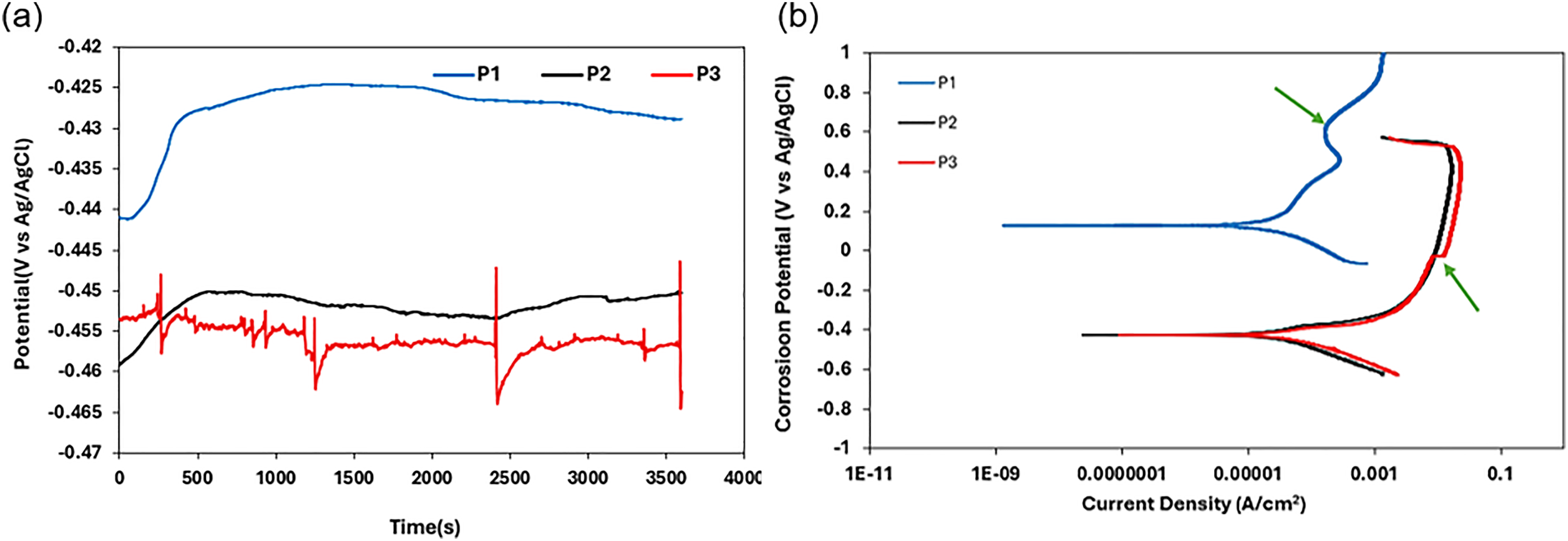
(a) OCP and (b) potentiodynamic polarisation curve of as-cast HCCI alloys in 0.5 M H2SO4 solution.
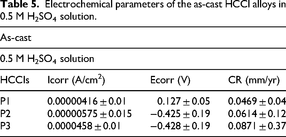
The potentiodynamic polarisation curves (Figure 8(b)) corroborate the observations that sample P1 showed clear signs of pitting (green arrow) with a defined but intermittently fluctuating passive region. Sample P2 produced the smoothest curve, most consistent passive plateau without marked fluctuations while sample P3 generated the largest increase in current density in the passive region, indicating rapid dissolution (green arrow) and film instability. These behaviours can be observed in the Icorr data (Table 5), where sample P3 records the highest Icorr (most severe corrosion), sample 2 is intermediate and sample P1 exhibits the lowest Icorr, confirming its superior resistance to material loss under acidic conditions.
Electrochemical parameters of the as-cast HCCI alloys in 0.5 M H2SO4 solution.
The SEM images in Figure 9 show that corrosion in 0.5 M H₂SO₄ are mainly localised corrosion and matrix dissolution. Sample P1 showed mild matrix dissolution with shallow pits and grooves primarily along carbide boundaries, consistent with localised attack and a relatively protective passive film (Figure 9(a)). Sample P2 displayed localised corrosion at carbide–matrix interfaces with matrix undercutting and uneven material loss, indicating selective matrix dissolution that left carbides partially exposed (Figure 9(b)). Sample P3 experienced extensive matrix dissolution and carbide–matrix interface dissolution, leading to widespread corrosion on the surface and a network-like exposure of carbides in some areas (Figure 9(c)). This morphology aligns with the potentiodynamic results showing the most aggressive corrosion in sample P3. Overall, the corrosion behaviour in acid reflects differences in passive film stability and the preferential corrosion of the matrix and carbide interfaces, with sample P1 forming a moderately protective but somewhat unstable film. Sample P2 showing better passive stability but localised matrix attack, and sample P3 exhibiting rapid matrix dissolution and passive film breakdown.
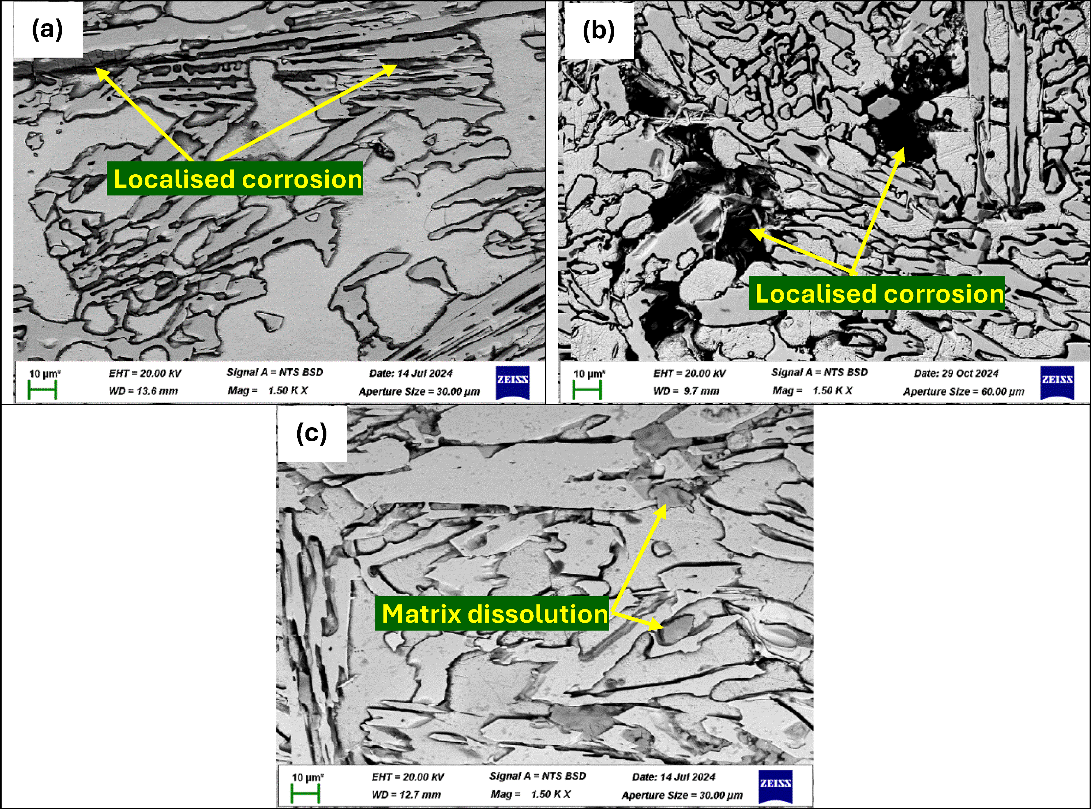
BSE-SEM images of surface morphology of as-cast P1 (a) P2 (b) and P3 (c) after electrochemical testing in 0.5 M H2SO4 solution.
Corrosion behaviour of heat-treated HCCI alloys
NaCl solution
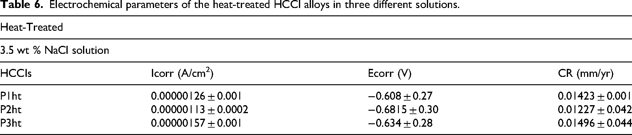
The OCP and potentiodynamic polarisation curves of the heat-treated HCCI alloys in 3.5 wt% NaCl solution are shown in Figure 10. In 3.5 wt% NaCl, all three heat-treated samples exhibited fluctuations (Figure 10(a)), indicating the passive-film breakdown under chloride attack. Sample P1ht began at the most noble potential and then drifted downward with some instabilities, exhibiting a relatively robust film that resisted sustained dissolution. Samples P2ht and P3ht started at more active potentials and followed nearly overlapping with fluctuations, signifying similarly uniform but slightly less durable passive layers (Figure 10(a)). The potentiodynamic polarisation curves (Figure 10(b)) corroborated with OCP observations such that sample P1ht displayed small fluctuations in its passive region which was indicative of localised dissolution. Sample P2ht produced the smoothest, most consistent passive plateau without pronounced disturbances and sample P3ht showed marginally higher current responses in the passive zone, pointing to slightly greater film instability and active dissolution (Figure 10(b)). These behaviours are observed in the Icorr data (Table 6), where sample P3ht records the highest Icorr, sample P1ht is intermediate and P2ht exhibits the lowest Icorr, confirming its superior resistance to material loss in chloride environments. However, the heat-treated HCCI samples corrosion rates remain closely similar.
(a) OCP and (b) potentiodynamic polarisation curve of heat-treated HCCI alloys in 3.5 wt% NaCl solution.
Electrochemical parameters of the heat-treated HCCI alloys in three different solutions.
The SEM images after electrochemical testing showed localised pitting and material loss on all heat-treated samples (Figure 11). For sample P1ht, pits and cavities appeared mostly at carbide–matrix interfaces, with carbides remaining intact while selective dissolution affected the surrounding matrix (Figure 11(a)). The passive layer showed signs of partial breakdown in some areas, leaving the surface vulnerable to ongoing corrosion. Sample P2ht exhibited more severe corrosion with wider and deeper pits and interconnected corrosion pathways, indicating chloride ion infiltration and more extensive matrix degradation (Figure 11(b)). Sample P3ht showed similar but slightly varied corrosion patterns with deep grooves and some widespread matrix dissolution, leaving behind a carbide-dominated structure vulnerable to chloride attack (Figure 11(c)). These observations confirm that corrosion in 3.5 wt% NaCl primarily targets the metallic matrix near carbide interfaces, leading to selective dissolution and localised pitting in the heat-treated HCCI samples. Overall, all heat-treated samples exhibited comparable corrosion behaviour, consistent with the electrochemical data showing similar active dissolution.
BSE-SEM images of heat-treated P1ht (a), P2ht (b) and P3ht (c) after electrochemical testing in 3.5 wt% NaCl solution.
NaOH solution
The OCP and potentiodynamic polarisation curves of the heat-treated HCCI alloys in 0.5 M NaOH solution are shown in Figure 12. In 0.5 M NaOH, all three heat-treated samples exhibited an initial rise in open-circuit potential (Figure 12(a)), reflecting passive-film formation under alkaline conditions. Sample P1ht began at the most noble potential and, despite minor instabilities, maintained a relatively steady film compared to the others. Sample P2ht showed a smooth, consistent increase and eventually overtook P1ht in nobility, indicating progressively thickening protection. Sample P3ht exhibited the largest fluctuations signifying the weakest initial film stability, though it improved over time.
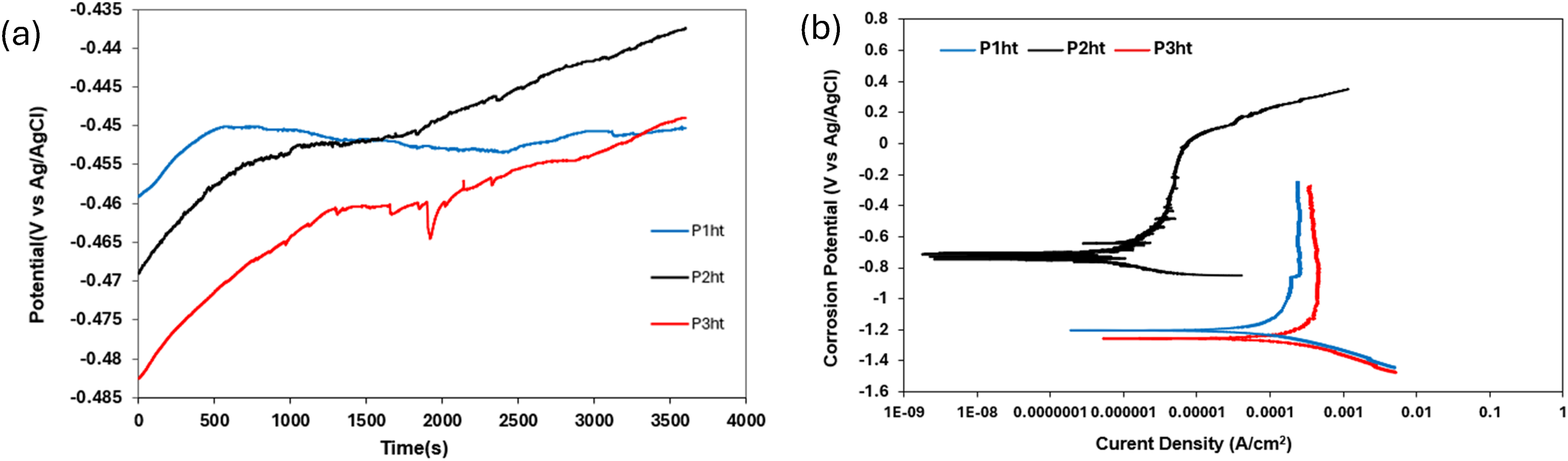
(a) OCP and (b) potentiodynamic polarisation curve of heat-treated HCCI alloys in 0.5 M NaOH solution.
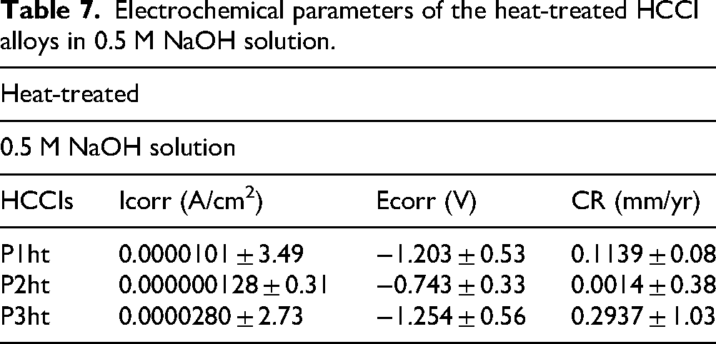
The potentiodynamic polarisation curves of the heat-treated HCCIs in 0.5 M NaOH solution are shown in Figure 12(b). Fluctuations were observed in the anodic curve of P2ht and later undergoes transpassivation. The polarisation curves had a lower corrosion potential for P1ht and P3ht. This shift suggests more negative potential and reduces electrochemical activity for P1ht and P3ht. The polarisation curves for P1ht exhibited a minor fluctuation in the passive region while P2ht showed a drastic shift towards higher potentials. This means that P2ht exhibited the best corrosion behaviour compared to P1ht and P3ht. Despite showing the best corrosion behaviour, P2ht also showed fluctuations in the passive region indicating instability in the passive film formation and suggested pitting corrosion. These behaviours are mirrored in the Icorr data (Table 7), where P2ht records the lowest Icorr (best corrosion resistance), P1ht is intermediate and P3ht shows the highest Icorr (most severe corrosion), confirming the ranking of passive-film effectiveness observed in both OCP and polarisation measurements.
Electrochemical parameters of the heat-treated HCCI alloys in 0.5 M NaOH solution.
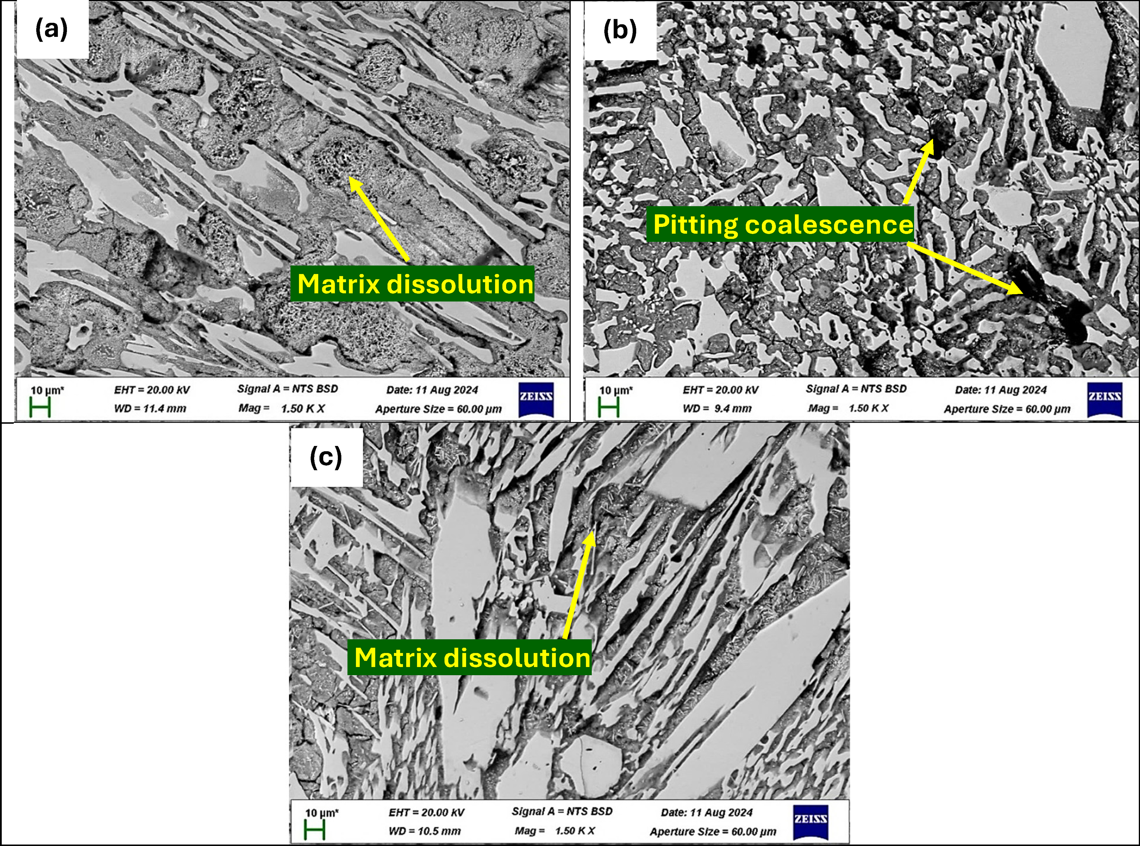
The SEM analysis of corroded surfaces in Figure 13 reveals corrosion initiation at carbide–matrix boundaries. Sample P1ht exhibits uneven, deep grooves around primary carbides, with faster dissolution at carbide edges than centres, consistent with fluctuating behaviour (Figure 13(a)). Sample P2ht shows more uniform and shallow etching of primary carbides, smoother carbide–matrix interfaces and minor pitting in secondary carbides, correlating with its better corrosion resistance despite some passive film fluctuations (Figure 13(b)). Sample P3ht presents more uniform and extensive dissolution of primary and eutectic carbides, with deeper pits on some carbides, explaining its higher corrosion rate and smoother passive film region (Figure 13(c)). Overall, P2ht forms the most protective passive layer with superior corrosion resistance, while P1ht and P3ht show weaker passivation and higher corrosion rates, with P3ht being the most electrochemically active sample.
SEM images of heat-treated P1ht (a), P2ht (b) and P3ht (c) after electrochemical testing in 0.5 M NaOH solution.
H2SO4 solution
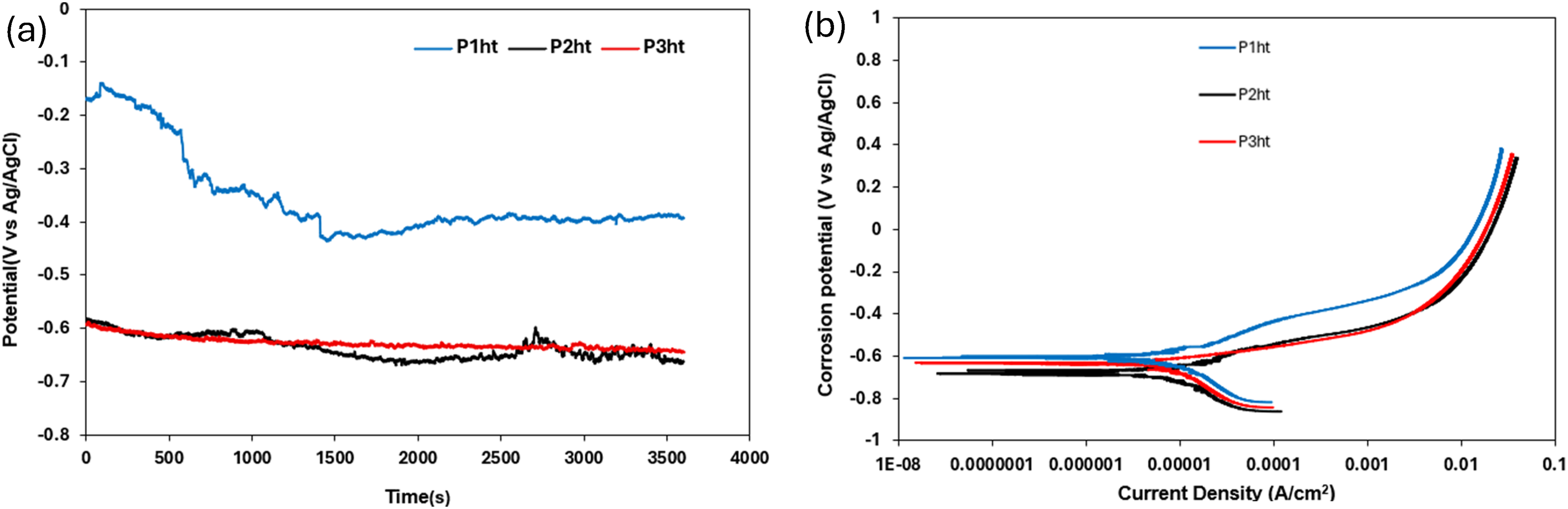
The OCP curves of the heat-treated HCCIs in 0.5 M H2SO4 reveal different passive-film behaviours (Figure 14(a)). Sample P1ht exhibits a gradual decline in potential with fluctuations before stabilising, signifying a comparatively resilient film that nonetheless undergoes localised breakdown under sulphate ion attack. Sample P2ht OCP curve shows fluctuations throughout the test and following a slightly increasing trend, continuing till the end. Sample P3ht curve exhibited a sharp, irregular dip, evidence of repeated passive-film breakdown and rapid repassivation events, which shows its poorest film stability. Aggressive sulphate ions continuously disrupt and reform the oxide film, while active dissolution of the metal matrix alters the local surface chemistry. Hydrogen evolution occurs as part of the cathodic reaction, and variations in hydrogen gas formation can temporarily block active sites, affecting the local pH and further destabilising the passive film. In addition, variations in surface preparation, temperature, dissolved-oxygen concentration, stirring rate and even slight reference-electrode drift all contribute to variability in the recorded potentials.27,32,38,39
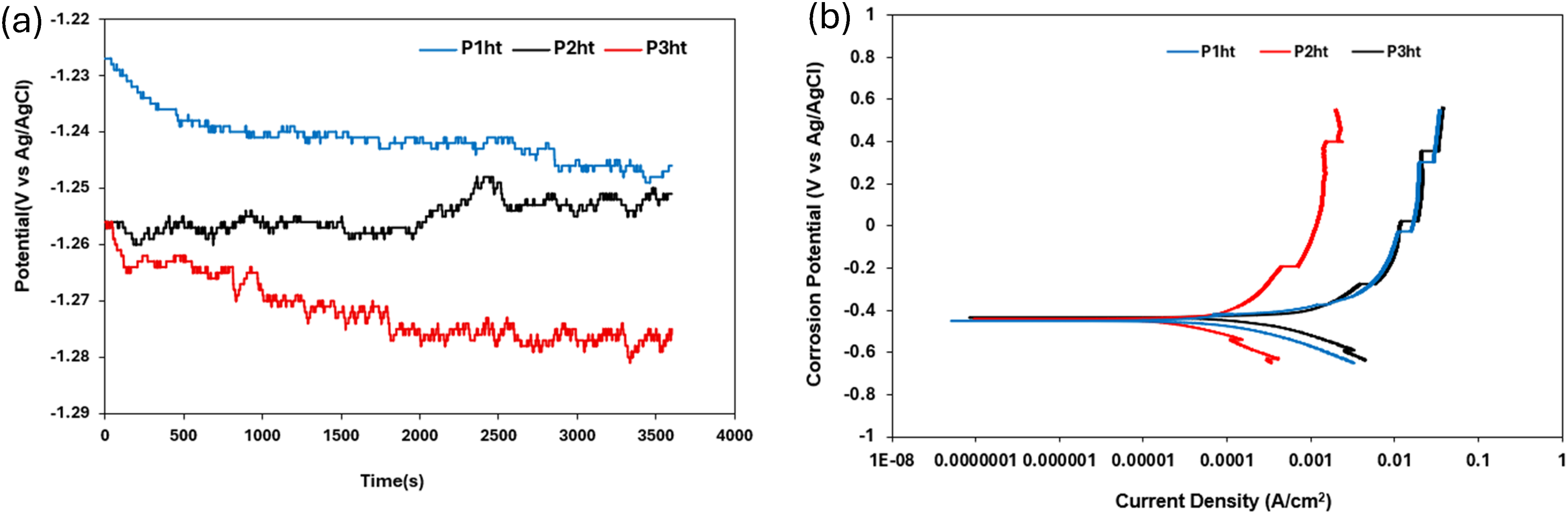
(a) OCP and (b) potentiodynamic polarisation curve of heat-treated HCCI alloys in 0.5 M H2SO4 solution.
The potentiodynamic polarisation curves (Figure 14(b)) corroborate these findings. All samples show similar anodic region behaviour with fluctuations in the passive region indicating instability in the passive film. The curves show noticeable fluctuations, suggesting frequent breakdowns and repassivation events. P3ht also shows a similar pattern to P2ht and P1ht however with an earlier onset passivation compared to the other curves. The fluctuations are sharp and irregular like in P1ht and P2ht, indicating instability in the passive film and rapid dissolution occurring once the film breaks down. These electrochemical behaviours are observed in the Icorr values (Table 8), where sample P1ht exhibits the lowest Icorr (best corrosion resistance), sample P2ht is intermediate and sample P3ht has the highest Icorr (most severe corrosion), confirming that P1ht retains the most robust passivation while P3ht is most prone to material loss under acidic conditions.
Electrochemical parameters of the heat-treated HCCI alloys in H2SO4 solution.
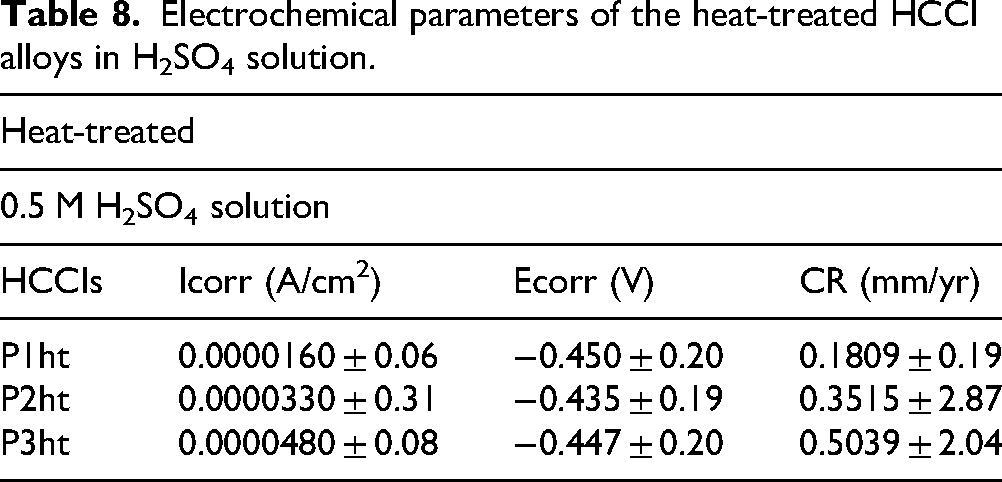
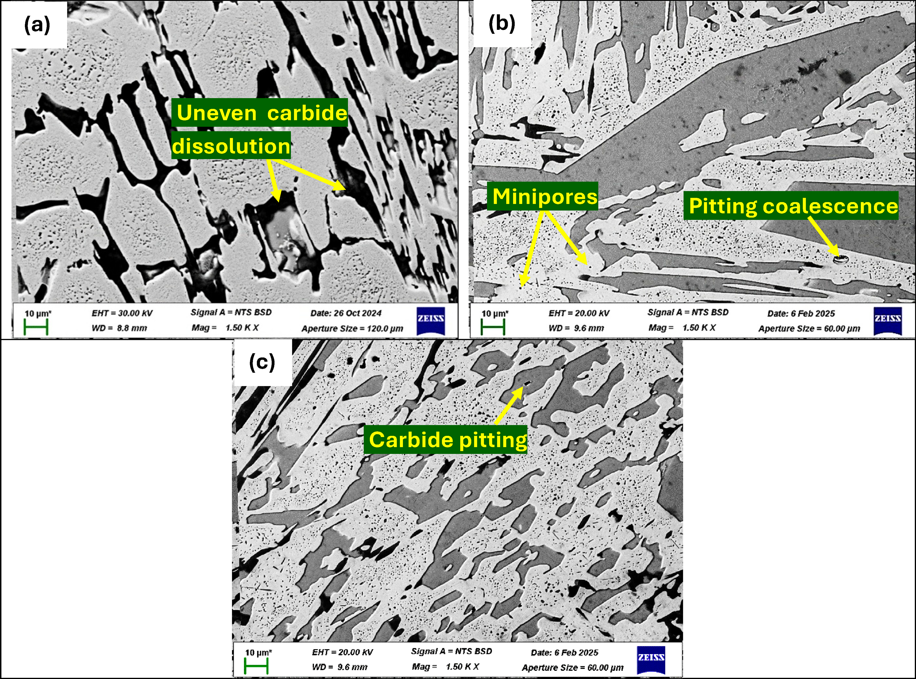
The SEM images of heat-treated HCCIs when exposed to 0.5 M H2SO4 reveal distinct corrosion morphologies across the three samples (Figure 15). Sample P1ht exhibits clear signs of pitting corrosion, characterised by deep cavities localised within the metallic matrix (Figure 15(a)). The primary carbides remain firmly embedded, though the surrounding matrix has begun to remove in some regions, exposing carbide edges. In sample P2ht, corrosion is notably more aggressive, with significant disintegration of the matrix observed (Figure 15(b)). Although the carbides appear mostly intact, there is evidence of weakening where the matrix has corroded beneath them, leading to early signs of carbide detachment in certain areas.
BSE-SEM images of heat-treated P1ht (a), P2ht (b) and P3ht (c) after electrochemical testing in 0.5 M H2SO4 solution.
The most severe corrosion occurs in sample P3ht, where substantial matrix dissolution results in a structure dominated by exposed and interconnected carbides (Figure 15(c)). Large pits and deep grooves are evident, indicating extensive loss of the metallic matrix. This deterioration causes some carbides to become partially unattached, and the surface appears highly porous, demonstrating widespread corrosion penetration. Overall, the progression of corrosion severity follows the sequence from P1ht to P3ht, aligning well with the electrochemical measurements that showed fluctuating passive film stability and active dissolution cycles. These findings indicate that the passive film undergoes continuous breakdown and repair, with P3ht experiencing the greatest instability and matrix degradation.
Discussion
Corrosion behaviour of as-cast and heat-treated HCCIs in chloride solution
Increasing chromium in HCCIs improves corrosion resistance by forming a stable passive layer that protects the surface from degradation.11,40,41 Lowering carbon content reduces the size and number of primary carbides, refining the microstructure and decreasing potential corrosion initiation sites.26,42 Increasing chromium in HCCI alloys forms a more stable passive film and improves corrosion resistance. 11 However, a greater carbide fraction locks more chromium into carbide phases and reduces the chromium available in the adjacent matrix. Local Cr depletion at carbide–matrix interfaces weakens the passive film and creates anodic sites that promote microgalvanic activity and selective matrix dissolution.37,43 At the same time, an increased number and area of carbide–matrix interfaces provide more locations for chloride access and more sites for galvanic coupling, so higher carbide volume fractions favour deeper and more extensive local attack.11,20 A finer and more uniform carbide distribution enhances passivation and reduces localised corrosion, resulting in a stable OCP and slower corrosion.42,44,45 In 3.5 wt% NaCl solution, the as-cast HCCI samples (P1, P2, P3) mainly showed pitting and microgalvanic corrosion, with sample P1 (Figure 5) showing the least degradation. The fine and homogeneous M₇C₃ carbides in P1 help form a stable passive film by reducing weak points where chloride ions can penetrate.32,35 Small, evenly distributed carbides hinder chloride-induced passive layer breakdown, improving resistance. 44 Pitting was due to chloride attack compromising the film, while microgalvanic corrosion occurred at carbide–matrix interfaces due to potential differences between Cr-rich carbides and the matrix. Overall, carbide distribution and chromium availability strongly influenced corrosion behaviour, with P1 exhibiting the lowest rate due to a continuous passive layer.
Sample P2 had more primary and eutectic carbides, forming a partial network in the matrix. Its lower chromium content left less free chromium for a strong passive film, leading to slightly higher corrosion than P1. 45 The interconnected carbides provided more pathways for chloride interaction and microgalvanic attack. However, P2 resisted corrosion better than P3 due to finer carbides and more uniform interfaces, which reduced localised attack. The matrix stayed mostly intact with some local interface weakening. P3 showed the highest corrosion rate due to coarse, uneven carbides. Large plate-like carbides, combined with chromium-depleted zones at carbide–matrix interfaces, weakened passive film stability.11,43,46 Chloride ions easily attacked these weak points. The uneven microstructure caused galvanic couples, where carbides acted as anodic sites, intensifying local reactions. 11 This led to deep and irregular corrosion and matrix disintegration, with detached carbides. Large carbides and high electrochemical potential differences caused an unstable corrosion profile in P3.
In 3.5 wt% NaCl solution, heat-treated samples (P1ht, P2ht, P3ht) also showed pitting and microgalvanic corrosion. Chloride ions caused passive film breakdown, especially at carbide–matrix interfaces. Heat treatment refined and redistributed M₇C₃ carbides, which influenced corrosion behaviour. Secondary carbides can both promote and retard corrosion. The secondary carbides can remove chromium locally and weaken the passive film, increasing localised attack,20,46 but when they are fine and evenly distributed they strengthen the matrix and reduce corrosion rates. 46 Matrix homogenisation during heat treatment reduced segregation, leading to more uniform corrosion. The redistribution of elements to more uniform distribution through the matrix homogenisation limits the areas of extreme segregation of chromium and carbon thereby causing more uniform corrosion of the matrix. Although secondary carbides affected corrosion initiation, primary carbide morphology remains an important factor rather than the sole controlling factor. 46 P1ht showed significant improvement due to finer carbide dispersion and better chromium redistribution. This refined structure reduced microgalvanic corrosion, resulting in more uniform surface corrosion rather than deep pits. The passive film remained stable, and chloride ions had fewer entry points. Compared to P1, P1ht showed less matrix degradation or carbide detachment due to the strengthened matrix. P2ht also improved, despite slight coarsening of carbides. Secondary carbides strengthened the matrix and redistributed chromium, allowing for a stronger passive layer and reduced galvanic activity. Corrosion was slower and more uniform, with less matrix damage than in as-cast P2. P3ht transformed the most, with large carbides reshaping into smaller, blocky structures, reducing their surface area and galvanic coupling. The denser carbide network and secondary carbides strengthened the matrix, improving resistance. The matrix type is also important. A mainly austenitic matrix tolerates carbides better than a martensitic or brittle matrix because austenite is less likely to crack at carbide interfaces and it supports a more stable passive film. 47 Although P3ht still had the highest corrosion rate among heat-treated samples, it performed far better than as-cast P3 due to better morphology and matrix integrity. Therefore, primary carbide morphology acts together with the size, distribution and volume of secondary carbides and with the matrix type to determine the overall corrosion response.20,38,39,46,48,49
Overall, heat treatment improved corrosion resistance by refining carbide morphology and redistributing chromium evenly. These changes reduced weak points and shifted corrosion from severe interface attack to more uniform dissolution. Heat-treated samples showed corrosion rates about 10 times lower than their as-cast counterparts. A fine, homogeneous microstructure with even chromium enrichment is essential for corrosion resistance in chloride-rich environments.
Corrosion behaviour of as-cast and heat-treated HCCIs in alkaline solution
In an NaOH environment, carbides corrode first because they have a lower self-corrosion potential than the matrix.39,48 In NaOH solutions, the primary corrosion mechanism involves the degradation of the carbides. Clegg and McLeod
50
and Liu et al.
51
reported that at lower temperatures, significant corrosion occurs at the carbide component, while at higher temperatures, the matrix corrodes preferentially, exposing carbide particles to mechanical damage. As the carbides dissolve, they leave behind more matrix and more chromium gets released to form a stronger passive film, which helps form a stronger protective passive film. The equation governing the cathodic reaction at the matrix is shown in Equation (1).
52

This is the same behaviour observed in the strong passive region of the sample corroded in NaOH as shown in Figure 7. This behaviour can be attributed to the fact that in highly alkaline environments, the carbides corrode preferentially over the metal matrix due to their lower self-corrosion potential.50,51
In 0.5 M NaOH solution, the primary type of corrosion for the as-cast HCCI samples (P1, P2 and P3) were selective carbide dissolution. Due to their lower self-corrosion potential than the matrix, the carbides corroded preferentially in the strongly alkaline environment, leaving a matrix rich in chromium that progressively developed a passive layer. The corrosion behaviour in NaOH solution is primarily influenced by the volume and distribution of carbides as well as the progressive release of Cr as the primary and eutectic carbides dissolve. In the NaOH solution, the carbides tend to corrode preferentially, leaving behind more of the matrix. As the carbides dissolve, additional chromium is gradually released, which slowly strengthens the passive film. Corrosion resistance in the as-cast samples is mainly controlled by the formation of a passive film, and this is strongly affected by the carbide volume, distribution and size. In sample P1, there is more chromium available to build a strong passive film, but very few primary carbides were formed. This means that when the NaOH solution attacks, it preferentially dissolves the few carbides available. Because these carbides are small, they tend to dissolve deeper rather than spreading out, and the large volume of the solution quickly overwhelms them. In addition, the wider dendrite spacing in sample P1 creates more active sites for corrosion, thus, even though chromium is released to form a passive film, the overall corrosion rate remains high.
In sample P2, the volume of carbides is much higher than in sample P1, which initially uses up some of the chromium required for a passive film formation. However, the carbides in sample P2 are more homogeneous and densely packed, with a smaller, more hexagonal shape. This reduces the interactions between the carbides and the matrix that lead to micro-galvanic corrosion. The more even distribution helps the passive film to develop steadily as the carbides dissolve deeper rather than wider, favouring localised attack due to rapid passivation, eventually strengthening the film and lowering the corrosion rate over time. In contrast, sample P3 has carbides that are larger and more dispersed than in sample P2. Their larger size gives them a greater surface area for dissolution, so they corrode faster on the surface, and the corrosion occurs wider rather than deeper. This larger surface attack initially compromises the localised protective effect of the passive film and increases the corrosion rate compared to sample P2, though over time the extra chromium released helps to improve the film and reduce corrosion.
A critical distinction in the corrosion attack morphology is observed when comparing the as-cast samples (Figure 7) and the heat-treated samples (Figure 13). This difference is fundamentally driven by the availability of free chromium needed for the protective passive layer formation and the specific microstructural features of each sample. In the as-cast condition, the selective dissolution of primary carbides rapidly releases sufficient chromium, leading to the immediate formation of a strong, stable passive film. 9 This film effectively limits the lateral spread of corrosion and drives the attack to be predominantly deep and localised, as evidenced by the deep dissolution in sample P2. Conversely, the heat-treated samples exhibit a morphology characterised by wider, more laterally aggressive surface dissolution. The precipitation of secondary carbides significantly depletes the available free chromium, which hinders the instantaneous formation of a strong passive film. 49 This compromised supply causes the corrosion to spread wider across the carbide surface.
After heat treatment, the formation of secondary carbides further depletes the chromium available for building the passive film. Consequently, in sample P1ht, the already few carbides are even less effective at releasing chromium; thus the passive film 52 becomes weaker, leading to deeper carbide corrosion and a higher overall corrosion rate. In sample P2ht, although the carbides remain homogeneous after heat treatment, carbide coarsening slightly increases the surface area exposed to the solution, causing a bit more surface dissolution (wider attack) compared to the deep attack seen in P2. For sample P3ht, the larger volume and size of carbides mean that even more chromium is tied up in secondary carbides, while the increased surface area leads to wider, more aggressive corrosion. The as-cast samples had far superior corrosion resistance in the NaOH environment compared to the heat-treated samples due to the strong and stable passive film formed in the as-cast from the onset, because more chromium was readily available to form the passive film. Additionally, the precipitation of secondary carbides tied up more of the chromium which would have slowed down the corrosion rate in the samples. The slower release of the tied-up chromium led to a slower building of the passive layer. 53 This is evident in Figure 12 where all the samples begin with a very strong and stable passive layer which stabilises in a shorter period, whereas in the OCP in Figure 12(a) of the heat-treated samples shows a gradual increase in the building of passive film overtime. This is also evident in the lower potential to corrosion exhibited by the heat-treated samples in the potentiodynamic curves in Figure 12(b) as opposed to the higher potential observed for the as-cast samples. Overall, the main mode of corrosion resistance in NaOH is the formation of a stable passive film, and a homogeneous, densely packed carbide network helps to reduce the surface area exposed to the solution, thereby limiting corrosion.
Corrosion behaviour of as-cast and heat-treated HCCIs in acidic solution
As the passive film degrades, weak areas undergo localised breakdown, allowing acid penetration and causing pitting or crevice corrosion along grain boundaries. This disrupts the electrochemical balance, lowering the corrosion potential.54,55 Sulphate ions further hinder film stability, delaying repassivation and causing a steady potential drop.52,56–58 The equation governing the anodic reaction of the matrix is shown in Equation (2).
52

This behaviour is seen in the OCP and polarisation curves of as-cast HCCI samples in H₂SO₄ (Figure 9). In acidic media, the matrix is more anodic than carbides, causing selective dissolution at carbide–matrix boundaries. 58 The M₇C₃ carbides, which stabilise the passive film in neutral and alkaline solutions, are less effective in H₂SO₄ due to the acid disrupting the chromium-rich oxide layer.59,60 This exposes carbide–matrix interfaces, resulting in grooves and microstructural damage. 43 Localised material removal occurs where corrosion is severe, while other areas remain intact. Such non-uniform corrosion shows that carbide–matrix interfaces are key initiation sites.59,61 Increased carbide formation reduces chromium available for passivation, raising corrosion rates. 60
The increase in matrix attack observed in H₂SO₄, particularly in the high-carbide as-cast sample P3 (Figure 9(c)) and in its heat-treated counterpart P3ht (Figure 15(c)), compared to the lower carbide samples, is primarily caused by the severity of microgalvanic corrosion. First, in the as-cast samples, increasing the carbide fraction (from P1 to P3) severely enhances matrix attack. The high volume and interconnected network of M7C3 carbides in P3 create an exponentially larger surface area of active carbide–matrix interfaces. Since the carbides act as the cathode and the matrix as the anode, this increased cathodic area concentrates the electrochemical load onto the surrounding anodic matrix, forcing rapid and widespread dissolution of the matrix material at these boundaries.
In 0.5 M H₂SO₄, as-cast samples (P1, P2, P3) showed active dissolution and galvanic corrosion. The corrosion in H₂SO₄, is consistently initiated at these large M7C3 phases, which act as the cathode. The acid promoted continuous matrix dissolution by preventing a stable passive film formation. Corrosion depended on carbide volume, distribution and available chromium. Sample P1 had the highest resistance due to its lower carbide content and higher chromium availability for passivation. The reduced carbide sites also lowered acid attack. P2 showed moderate resistance due to higher carbide volume and less free chromium. 45 More carbides increased galvanic interactions at interfaces, leading to frequent film breakdown and repassivation. P3 had the lowest resistance due to its high, interconnected carbide network and limited chromium. The large carbides created many galvanic sites, causing rapid localised corrosion and unstable film formation.
The heat treatment further exacerbates matrix attack through a combination of micro-galvanic enhancement and severe chromium depletion. The precipitation of secondary carbides not only introduces numerous new, small cathodic sites for galvanic action 62 but, more critically, it consumes chromium from the adjacent matrix. 9 These chromium-depleted regions are highly anodic and chemically unstable in the H₂SO₄, environment, leading to accelerated and deeper matrix dissolution around the newly formed secondary phases. In 0.5 M H₂SO₄, heat-treated samples (P1ht, P2ht, P3ht) also showed active dissolution and galvanic corrosion. Therefore, the acid aggressively attacks the weakened matrix surrounding both the coarse M7C3 carbides and the new secondary phases. Sulphate ions blocked stable film formation, accelerating matrix dissolution. Higher carbide volumes reduced free chromium, increasing corrosion rates. P1ht showed the best resistance due to its fine, uniformly distributed primary carbides, which promoted uniform dissolution and limited localised attack. Increased chromium availability reduced corrosion, but secondary carbide precipitation created new galvanic sites compared to P1. P2ht showed moderate resistance due to higher carbide content and coarsening, which increased micro-galvanic activity. However, its homogeneous structure reduced exposed surface area, lowering the rate compared to P3ht. P3ht had the worst resistance due to large carbides, chromium depletion and extensive galvanic sites, causing frequent film breakdown and rapid attack. The increased carbides restricted passive film continuity, resulting in severe dissolution.
Overall, the as-cast samples showed marginally better corrosion resistance compared to the heat-treated samples by a factor of 0.188 ± 0.13. This slight advantage underscores the critical role of free chromium content in stabilising the matrix against aggressive acidic attack. Secondary carbides increased corrosion by reducing chromium availability and acting as galvanic sites. Differences in resistance between P1ht and P3ht were due to carbide size, chromium levels and microstructural homogeneity. The severity of corrosion in H₂SO₄, emphasises the importance of balancing the Cr/C ratio in the alloy's design, aiming to minimise the cathodic carbide surface area while maximising the available Cr in the anodic matrix to form a stable passive film. 53 The highest corrosion rates occurred in H₂SO₄, followed by 3.5 wt% NaCl, while NaOH showed the lowest due to its passive film-promoting nature.
Conclusions
This study demonstrates that the corrosion behaviour of HCCIs is strongly governed by microstructural characteristics such as carbide volume fraction, size, morphology and distribution, as well as chromium availability within the matrix. The type and extent of corrosion varied significantly across the three environments studied. In chloride-rich (3.5 wt.% NaCl) environments, the dominant corrosion mechanisms were pitting corrosion and micro-galvanic attack, initiated at carbide–matrix interfaces where chromium segregation created weak passive zones. A microstructure with fine, evenly distributed carbides and high matrix chromium content promoted a more stable passive layer and reduced localised corrosion. In alkaline (0.5 M NaOH) solution, the primary mode of corrosion was selective carbide dissolution, where carbides corroded first due to their lower self-corrosion potential compared to the matrix. This led to gradual chromium release, which supported passive film formation over time. Homogeneous and compact carbide distribution helped reduce surface exposure and delayed corrosion onset. In acidic (0.5 M H2SO4) environments, corrosion occurred mainly through active-matrix dissolution and localised galvanic corrosion. Aggressive sulphate ions continuously broke down the passive film, and areas with high carbide volume and low chromium availability were especially vulnerable. Coarse, interconnected carbides and uneven matrix composition intensified galvanic interactions, leading to more severe corrosion. Heat treatment modified these behaviours, altering the microstructure by refining carbide distribution and promoting secondary carbide precipitation. While these changes enhanced homogeneity and reduced corrosion in neutral environments, they also introduced new galvanic sites and reduced free chromium, which increased corrosion in acidic conditions.
Supplemental Material
sj-docx-1-ces-10.1177_1478422X261416688 - Supplemental material for Influence of Cr/C ratio on microstructure and corrosion of hypoeutectic high chrome cast irons
Supplemental material, sj-docx-1-ces-10.1177_1478422X261416688 for Influence of Cr/C ratio on microstructure and corrosion of hypoeutectic high chrome cast irons by Zaynab Adam Cader, Olufemi Sylvester Bamisaye, Desmond Klenam, Michael Oluwatosin Bodunrin and Olanrewaju Sylvester Omole in Corrosion Engineering, Science and Technology
Footnotes
Author note
This article is dedicated to my late supervisor Professor Josias Willem Van der Merwe.
Acknowledgements
The authors gratefully acknowledge the support of the AESA-RISE Fellowship Programme (AEPDF 18-03). This programme is run by the African Academy of Sciences (AAS) with funding from the Carnegie Corporation of New York. AESA-RISE operates under the AAS's AESA initiative, a partnership between the Academy and the African Union Development Agency-NEPAD (AUDA-NEPAD).
Author contributions
Zaynab Adam Cader was involved in experimental conceptualisation, investigation, writing of the original draft till finalisation and project management. Olufemi Sylvester Bamisaye was involved in writing and reviewing the original draft. Michael Oluwatosin Bodunrin and Desmond Klenam were involved in experimental conceptualisation, project management, funding, reviewing and editing of the original draft till finalisation. Olanrewaju Sylvester Omole was involved in reviewing and editing the original draft.
Funding
The authors disclosed receipt of the following financial support for the research, authorship and/or publication of this article. This work was supported by the Alliance for Accelerating Excellence in Science in Africa (grant number AEPDF 18-03).
Declaration of conflicting interests
The authors declared no potential conflicts of interest with respect to the research, authorship and/or publication of this article.
Data availability statement
The data that support the findings of this study are available from the corresponding author upon reasonable request.
Supplemental material
Supplemental material for this article is available online.