
Abstract
The microstructures and mechanical properties (tension strength Rm, yield strength Rt0.5 and impact energy Akv) of the low-nickel alloy steels 08Ni, 12CrNi and 20CrNi with and without heat treatment were measured and analyzed, as well as the common gathering pipeline steels (X60 and 16Mn). The results indicate that the mechanical properties of the low-nickel alloy steels with heat treatment are superior compared with other test materials, in the sequence as follows: (20CrNi) > (12CrNi) > (08Ni) > 20CrNi > 12CrNi > X60 > 08Ni > 16Mn (“(steel)” indicates the material with heat treatment, and “steel” means without). The weight-loss method was used to test the corrosion rates of the test materials exposed to a simulated oilfield environment for 168 h at 90 °C with the CO2 partial pressure and total pressure 2 MPa and 10 MPa, respectively. The systematical characterization with scanning electron microscope and X-ray diffraction displayed the different micro-morphology of corrosion scales formed on the surface of the test materials with FeCO3 as the only detected composition of corrosion product. That the low-nickel alloy steels with heat treatment showed a higher corrosion resistance than those without, mainly resulted from the different microstructures of the matrix, the characteristics of corrosion scale and the composition of elements.
Keywords
Introduction
Carbon dioxide (CO2) corrosion is defined as the attack on metal by aqueous CO2 environments. The formation of carbonic acid (H2CO3) after CO2 dissolving into aqueous medium lowers the pH of the solution, 1 and creates a very corrosive environment that can cause severe corrosion damage to the production and transportation devices in crude oil and natural gas industry.2,3 The corrosion is a complex phenomenon consisting of several simultaneous and interacting processes: three species (H+, H2CO3 and HCO3−) are reduced on the metal surface, accompanied by the corresponding anodic oxidation of iron, resulting in dissolution of the metal. 1 Recently, particularly because of enhanced oil recovery techniques based on CO2 injection into reservoirs and sweet gas production from ever increasing depths, 4 CO2 corrosion has gained new prominence with the advent.
Scanning electron microscope (SEM) and X-ray diffraction (XRD) are usually employed to systematically characterize the component and microstructure of the corrosion scale formed on a metal surface exposed to a CO2 environment. The main corrosion product of carbon steel is iron carbonate (FeCO3), which precipitates on the surface of steel when the product of the concentration of Fe2+ ions and that of CO32− ions exceeds the solubility product of iron carbonate (Ksp).5,6 The adherent and dense corrosion scale could provide good protection to the matrix by reducing mass transfer of the reactants and products between bulk solution and steel surface,7,8 actually acting as a physical barrier to restrict the diffusion transfer of aggressive species and prevent the steel from being further dissolved.9,10
Metal CO2 corrosion results from anode-cathode reactions and is affected by the important parameters such as temperature, CO2 partial pressure and aggressive ion such as Cl− and so forth, which are all associated with corrosion scale.11–14 Besides the information already referred to, more importantly, CO2 corrosion behaviors vary dramatically based on different materials and mining environments. Carbon steels do not yet meet the requirement in a harsh corrosive environment containing Cl− and wet CO2 gas. At present, efforts have been mainly focused on investigating the effects of the composition and microstructure on the corrosion resistance of Chromium (Cr)-enriched and Nickel (Ni)-enriched stainless steels, even the super Ni-base alloy. Heat treatments are sometimes recommended for alloy steels, providing higher volume fraction, better size distribution, higher strength, higher yield point, combined with appreciable ductility even in large sections.15,16 These properties are helpful to enhance the corrosion resistance. However, compared with Cr-enriched and Ni-enriched stainless steels, low-Ni and low-Cr alloys display a higher weldability and toughness. Simultaneously, Cr and Ni are both limited resources with a comparatively high price, hence the Cr and Ni alloying contents in steel are bound up with economic costs. Up to date, just a few literatures introduced corrosion resistant performance of material with low level Cr.17,18 CO2 corrosion behavior of low-Ni alloy has not been investigated over a long period of time. Especially, for the benefits of heat treatment for the corrosion resistance of low-Ni and low-Cr alloys, still no further attempts have been made. Obviously, it is significant to understand the microstructures and characteristics of the surface film induced from CO2 corrosion of low-Ni and low-Cr alloys under special conditions. The objective of this article is directed towards the effect of alloying elements contents on the corrosion resistant performance of the low-Ni alloy steels 08Ni, 12CrNi and 20CrNi. Especially the influence of heat treatment techniques and mechanical properties on corrosion behaviors and the characteristics of corrosion scales of three low-Ni alloy steels, along with the common gathering pipeline steels X60 and 16Mn in simulated oilfield environments, have been investigated. We intend to provide valuable information to achieve better materials selection for oil/gas pipelines and instruments.
Experimental
Materials preparation
The specimens were the low-Ni alloy steels 08Ni, 12CrNi, 20CrNi with and without heat treatment, as well as the common gathering pipeline steels X60 and 16Mn. The chemical compositions of the test materials are listed in Table 1, which were analyzed using the direct reading spectrometer (Baird Spectrovac 2000) on the basis of GB/T 4336-2002. The specimens of three low-Ni alloy steels were austenized at 900 °C, 910 °C and 950 °C, respectively, and then quenched in water. Finally, the quenched specimens were tempered at 220 °C, 500 °C and 550 °C for 2 h, respectively.
The chemical compositions of the test materials (wt.%).
The brackets represent the low-Ni alloy steels with heat treatment.
Metallograph and properties measurements
All the experiments were based on the criteria of ASTM E8 (Standard test methods for tension testing of metallic materials) 19 and ASTM E23 (Standard test methods for notched bar impact testing of metallic materials), 20 respectively. Microstructures of the test materials were detected by Model MeF3A metalloscope. Mechanical properties (tension strength Rm, yield strength Rt0.5 and impact energy Akv) of the test materials were measured by CMT5105 microcomputer control electronic universal testing machine (the strain rate: 1 mm/min) and JBZ-300 automatic impact testing machine, and the impact tests were performed at 0 °C. In addition, Rockwell Hardness was also conducted. In order to ensure the reproducibility, five specimens were tested to obtain the mechanical properties datum each time.
Weight loss tests
The stagnant weight loss tests were carried out in Cortest Autoclave Systems made in Cortest Corporation (USA), with the maximal experimental pressure 70 MPa, highest experimental temperature 350 °C and maximal volume 5 L. The simulated test conditions were determined according to the CO2 corrosion environment of one oil/gas well located in the Talimu oil field in the Northwest of China (the depth of the well was 4000 m, the CO2 partial pressure and total pressure at the well bottom were 2 MPa and 10 MPa, respectively, and the temperature was at 90 °C). The simulated solution was mainly composed of deionized water and pure chemical agents, and the concentrations were based on the chemical compositions of formation water extracted from the oil field, listed in Table 2.
The chemical compositions of formation water extracted from the oil field.
In order to ensure reproducibility, five specimens were tested to obtain the mechanical properties datum each time. The surface of specimens with the size of 40 × 10 × 3 mm were mechanically polished by emery sandpaper up to #800 progressively, then degreased with acetone, rinsed with absolute alcohol, and weighted with a balance (a precision of 0.1 mg), and finally mounted in a rack located in the high-temperature and high-pressure autoclave.
Before starting the test, pure N2 gas was led under pressure into the simulated solution to degas for 12 h, and then CO2 gas was put through into the autoclave. The temperature was controlled at 90 °C and the pressure was maintained at the invariable value of CO2 partial pressure and total pressure 2 MPa and 10 MPa (N2 gas was supplemented up to the total pressure), respectively. The corrosion test was carried out for 168 h. After the test, five specimens were rinsed with distilled water and absolute alcohol, and then divided into two groups: the corroded specimens in group one were descaled (the solution: 20 g Sb2O3 + 50 g SnCl2 + 1 L HCl (ρ = 1.19 g/L)), rinsed with water and absolute alcohol, dried in a natural state, and weighted again with the balance (a precise of 0.1 mg) to calculate the corrosion rate. The specimens in group 2 were not descaled, which would be used for surface analysis.
SEM and XRD measurements
SEM (Philips XL-20) was utilized to investigate micromorphology of the corrosion scale. The XRD experiment was performed using Japan D/MAX-2400 automatic XRD apparatus with Cu Ka radiation X-ray source at an accelerating voltage of 40 kV and a current density of 40 mA·cm−2. Before SEM and XRD, the samples were cleaned in acetone in order to remove the surface contamination.
Results and discussion
Metallograph and properties analysis
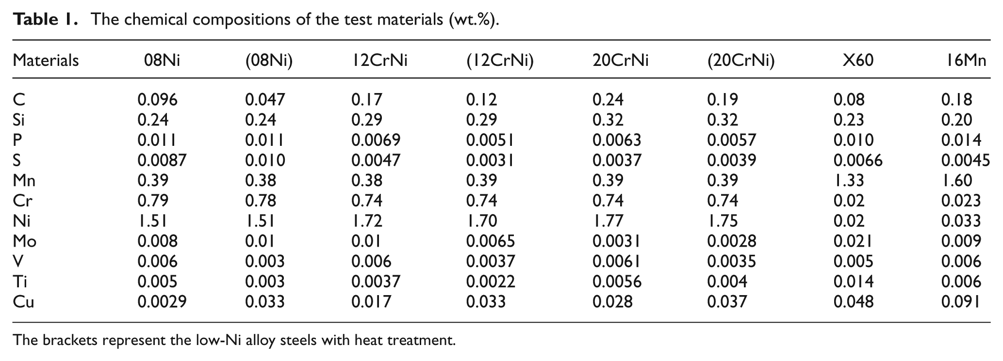
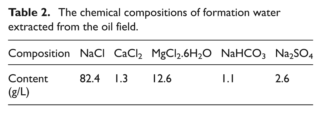
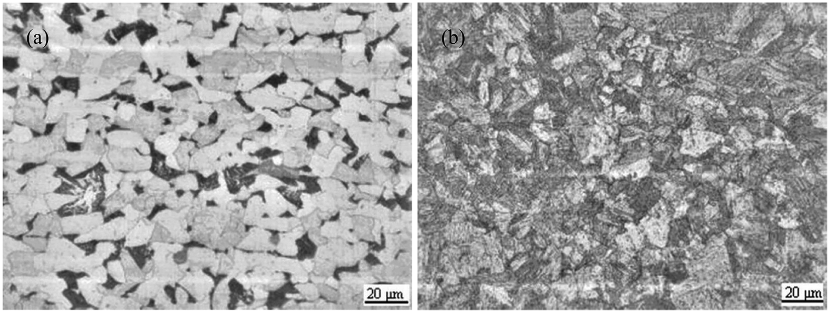
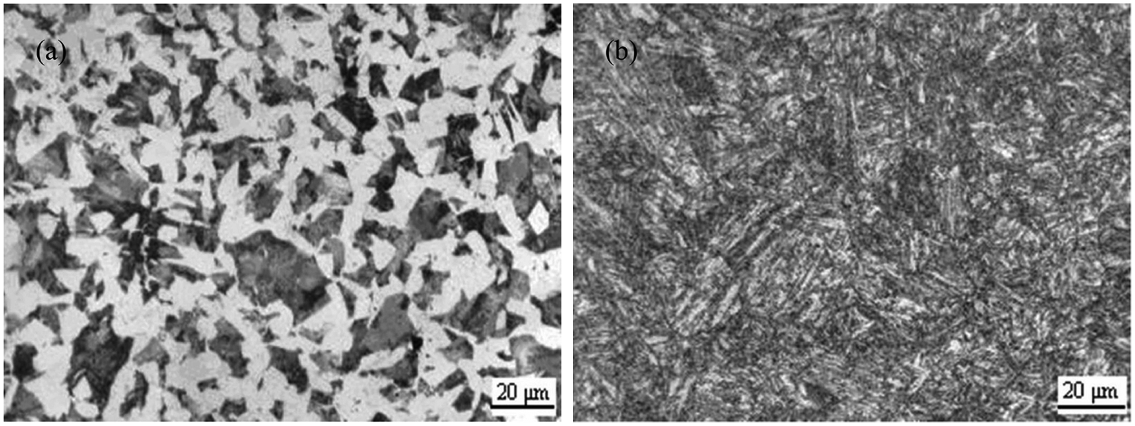
The microstructures of the three low-Ni alloy steels 08Ni, 12CrNi and 20CrNi without and with heat treatment are shown in Figures 1–3, respectively. The microstructures were changed and the grain was refined obviously by heat treatment: the microstructures of 08Ni without heat treatment are the ferrite and pearlite phases, while that of 08Ni with heat treatment is the tempered sorbite phase. A similar phenomenon was observed in both 12CrNi and 20CrNi steel. As we know, the loose surface layer could act as micro-channels of ion transfer and make a contribution to the corrosion process. The much more dense microstructures after heat treatment could hopefully affect the corrosion behavior of the test materials to some extent. Moreover, from the mechanical properties of 08Ni, 12CrNi and 20CrNi displayed in Table 3, the tension strength (Rm), yield strength (Rt0.5) and hardness (HRC) of the low-Ni alloy steels with heat treatment are superior compared with those without heat treatment, which allows the materials to meet the demands in the criterion of API Spec 5CT (Specification for casing and tubing). 21 Generally, by comparison, the mechanical properties of these specimens were in the sequence as follows: (20CrNi) > (12CrNi) > (08Ni) > 20CrNi > 12CrNi > X60 > 08Ni > 16Mn (“(steel)” indicates the material with heat treatment, and “steel” means without).
The microstructures of 08Ni: (a) without heat treatment; (b) with heat treatment.
The microstructures of 12CrNi: (a) without heat treatment; (b) with heat treatment.
The microstructures of 20CrNi: (a) without heat treatment; (b) with heat treatment.
The mechanical properties of the test materials.
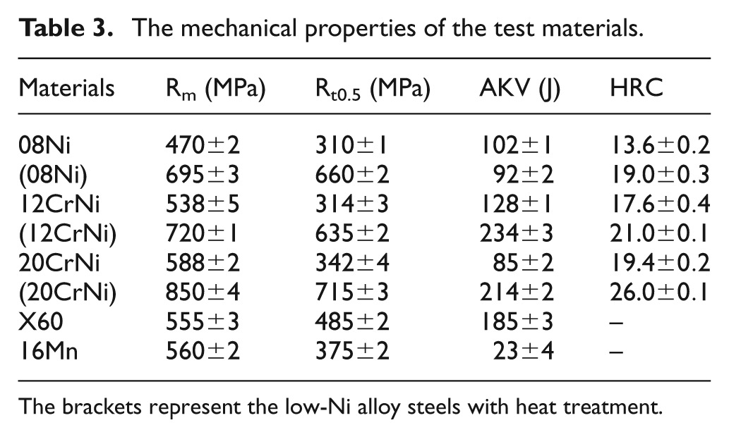
The brackets represent the low-Ni alloy steels with heat treatment.
Weight loss tests
From the standpoint of experimental condition, corrosion can be divided into dynamic corrosion and stagnant corrosion. In addition, from the standpoint of material failure forms, corrosion consists of stress corrosion cracking, hydrogen induced cracking and flowing enhanced corrosion. The stagnant corrosion was chosen here to measure the CO2 corrosion behaviors of three low-Ni alloy steels 08Ni, 12CrNi and 20CrNi without and with heat treatment, as well as the common gathering pipeline steels X60 and 16Mn. Compared with other types of corrosion, such as stress corrosion cracking and turbulent or flowing corrosion, stagnant corrosion demands the specimens are immersed into a stagnant corrosion medium, which prevents the material from cracking owing to the combined action of tensile stress and turbulent flow with the specific environment. For example, the flow factor induces the concentration gradients that influence the diffusion process of dissolved species in the solution, and then seriously affect the corrosion rate. Therefore, the stagnant corrosion could allow the observation to be concentrated on the different corrosion behaviors, resulting from the different composition in steels associated with comparatively simple environmental factors. With regards environmental parameters, high concentrations of Cl− ion and high temperature (90 °C) based on rigorous conditions of the simulated oilfield environment was applied in order to observe the severe corrosion behavior of the test materials. In general, temperature plays a definite role in CO2 corrosion environments, which seriously affects the formation rate of the corrosion product layer. At low temperature, though the protective layer will hardly form on the steel surface owing to the low deposition rate of iron carbonate, a lower dissolution rate of the matrix and lower mass transfer rate could lead to the lower corrosion rate. With increasing temperature, owing to the negative temperature gradient of iron carbonate, the corrosion product layers quickly form accompanied by the acceleration of mass transfer and corrosion product layer dissolution. Finally, the corrosion product layers become looser and porous, which can not supply the matrix with the effective protection, but increases the contacting area of corrosion reactions. Consequently, the corrosion rate generally reaches maximum when the temperature is around or above 80 °C.5,22,23
The corrosion rates (CR) of these materials measured in the simulated oil/gas environment containing CO2 are shown in Figure 4, in the sequence as follows: (12CrNi) < 20CiNi < (20CrNi) < 12CrNi < (08Ni) < 08Ni < X60 < 16Mn. It can be seen from the data that the corrosion rates of 12CrNi, 20CiNi and 08Ni, with heat treatment, are about 1.0704 mm·a−1, 1.1704 mm·a−1 and 1.5106 mm·a−1 compared with those without heat treatment about 1.3206 mm·a−1, 1.1006 mm·a−1 and 1.4203 mm·a−1, respectively. Generally, the materials with heat treatment, especially 12CrNi, are corroded more slowly than those without heat treatment. This result highlights that heat treatment promotes a good corrosion resistance for reinforcing steel. 24 However, the variation trend of the corrosion rates is not completely in accordance with that of the mechanical properties as described above, which might be ascribed to the different microstructures 25 caused by the heat treatment process of the materials or the test error of the weight loss method.
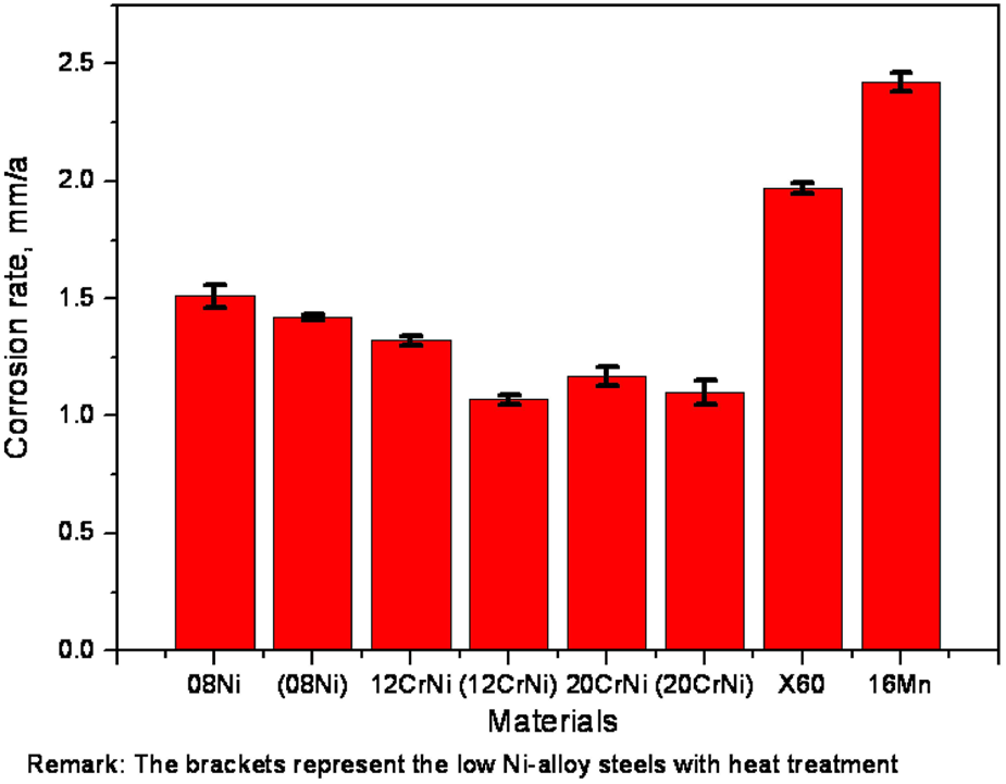
Corrosion rates of different materials at 90 °C.
In addition, the anti-corrosion performances of the low-Ni alloy steels are better than those of the common gathering pipeline steels (the corrosion rates of X60 and 16Mn are 1.9703 mm·a−1 and 2.4204 mm·a−1, respectively). It is well known that the alloying elements play a very important role on the material design to improve the anti-corrosion properties of the steels utilized in oil/gas wells. 26 The Ni element is sufficient for the resistance of materials to chloride-ion stress corrosion cracking. Moreover, the Cr element can improve resistance to high-temperature oxidation and hot sulfur-bearing gases. Consequently, the higher contents of Ni and Cr in low alloy steels than those in common gathering pipeline steels enhanced the corrosion resistance. According to the effects of the alloying elements, combined with the chemical compositions shown in Table 1 and the corrosion rates shown in Figure 4, it can be easily concluded that the corrosion resistance of 12CrNi with heat treatment is superior among the test materials.
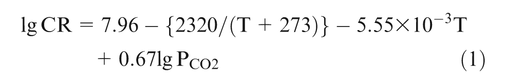
The experimental results were further compared with model predictions stated in the literatures. de Waard and Millams proposed equation (1) as one of the classic models to predict corrosion rates of steel in aqueous CO2 solutions based on the experimental results 27 . However, there is the applied limitation of equation (1), i.e. temperature should be lower than 60 °C, and PCO2 lower than 0.2 MPa. Grounded on the datum in the oil field, de Waard and Lotz constructed the more practical formula shown in equation (2). 28

where CR is the corrosion rate, mm·a−1, PCO2 is CO2 partial pressure, MPa, and T is experimental temperature, °C.
After substituting T and PCO2 with the chosen experimental parameters, CO2 partial pressure 2 MPa and the experimental temperature 90 °C, the predicting corrosion rates of steel was 18.8582 mm.a−1 and 14.5410 mm·a−1, respectively, on the basis of equations (1) and (2). Obviously, the predicting results are different from the experimental results, which could be owing to the effects of experimental temperature, medium composition, corrosion scales and alloying elements. However, compared with the predicting models, higher corrosion resistance of the test materials displayed from datum in experiments, which highlights the dramatic enhancement of Cr and Ni in low-Ni and low-Cr alloy.
SEM analysis of surface scale
Figure 5 exhibits the micro-morphology of corrosion scales formed on 08Ni low-Ni alloy steel without and with heat treatment. It is clear that the corrosion scale was looser and porous. Moreover, the crystal grains were bulky incompact, and interstitial in stacking. The phenomenon is in line with a higher corrosion rate. In addition, the large areas of corrosion scale formed on the surface of 08Ni low-Ni alloy steel without heat treatment were removed from the substrate surfaces, implying that the bonding strength is not high enough to anchor the surface of steel.
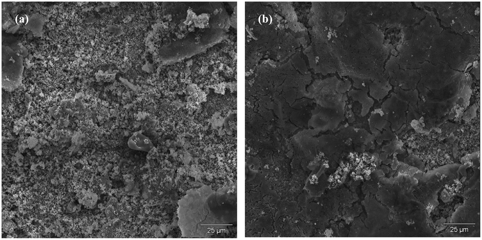
SEM micrographs of corrosion scale formed on 08Ni: (a) without heat treatment; (b) with heat treatment.
The micro-morphology of corrosion scales formed on 12CrNi and 20CrNi low-Ni alloy steels without and with heat treatment is presented in Figures 6 and 7, respectively, in which corrosion scales were all relatively dense, compact and completely covered the surfaces of the substrate. According to the relative dense corrosion scales formed on the samples, it can be speculated that the corrosion scale was well-bonded to the low-Ni alloy steels, and supplied the matrix of the materials with better protectiveness. At the same time, the corrosion scale of 12CrNi with heat treatment was found to be most dense among the test materials. This phenomenon is in good accordance with the lowest corrosion rate. By contrast, corrosion scales of 12CrNi without heat treatment were not uniform, thereby displaying a higher corrosion rate than those of 20CrNi without and with heat treatment.
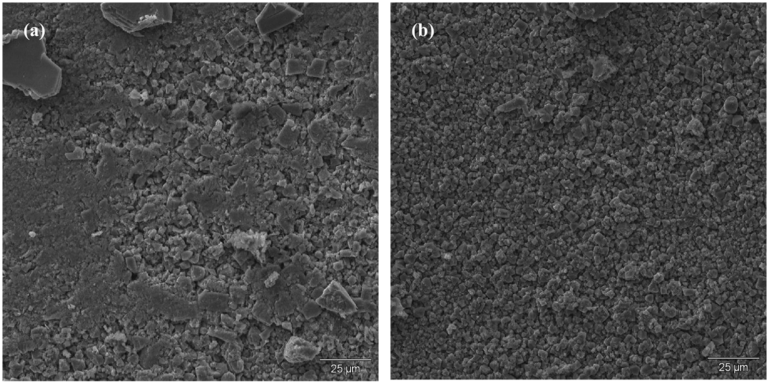
The micromorphology of corrosion scale formed on 12CrNi: (a) without heat treatment; (b) with heat treatment.
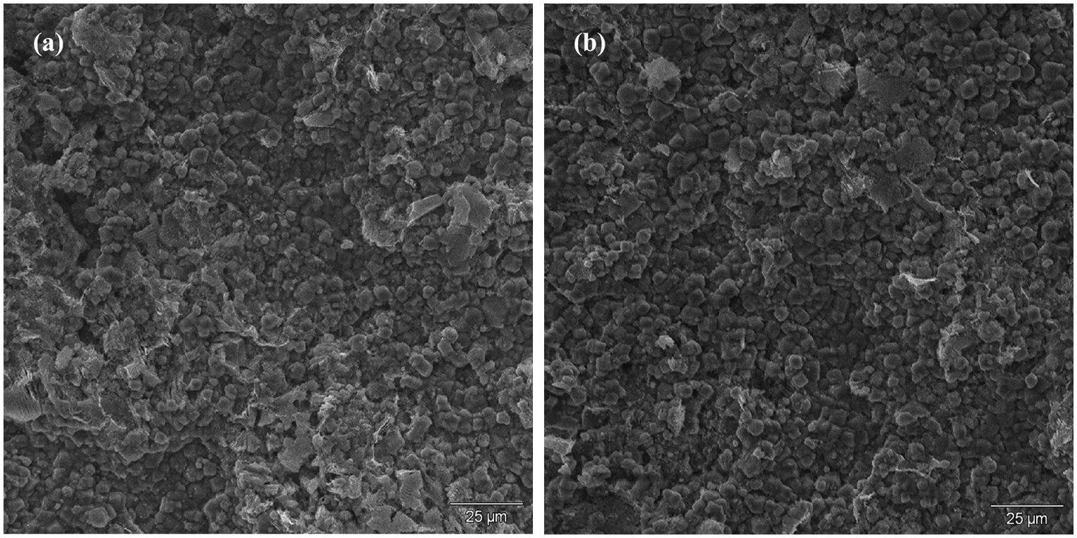
The micromorphology of corrosion scale formed on 20CrNi: (a) without heat treatment; (b) with heat treatment.
The micro-morphology of the common gathering pipeline steels (X60 and 16Mn) could be observed in Figure 8. Obviously, the crystal sizes of X60 were smaller than those of 16Mn, indicating the faster crystal growth for 16Mn pipeline steel. In addition, corrosion scale of 16Mn was looser than that of X60. To the best of our knowledge, the loose surface layer is full of holes, which provides mass transfer of corrosive ions for the micro-channels, therefore, corrosion attack on the steel is not effectively prevented. From the results obtained from SEM morphologies, it can be concluded that heat treatment has important effects on the microstructure of corrosion scales, further closely related to the formation of protective film on the surface of materials.
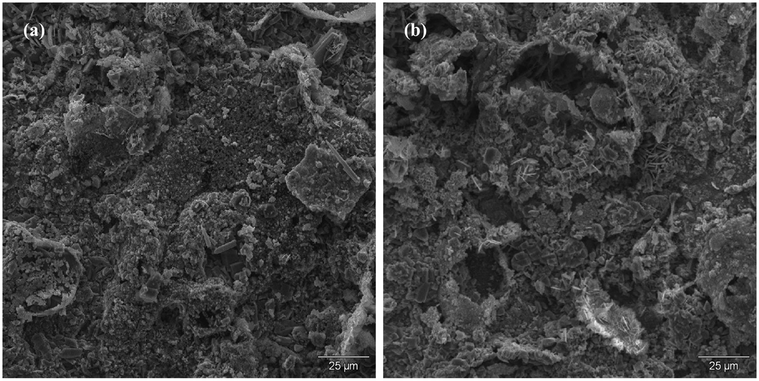
The micromorphology of corrosion scale formed on pipeline steels: (a) X60; (b) 16Mn.
XRD analysis of corrosion scale
XRD spectra obtained on corrosion scales of both 12CrNi and 20CrNi are shown in Figure 9(a) and (b), respectively. The spectrum revealed that the main phase in all corrosion scales was iron carbonate (FeCO3). In general, the stronger intensities of phase peak represent the higher content of FeCO3, indicating the more serious corrosion attack. Compared with the XRD spectrum in Figure 9, iron peaks from the substrate were detected, which reflected that the corrosion scale forming on 12CrNi with heat treatment was thinner than those in 12CrNi without heat treatment and 20CrNi with and without heat treatment, in accordance with the corrosion rates shown in Figure 4.
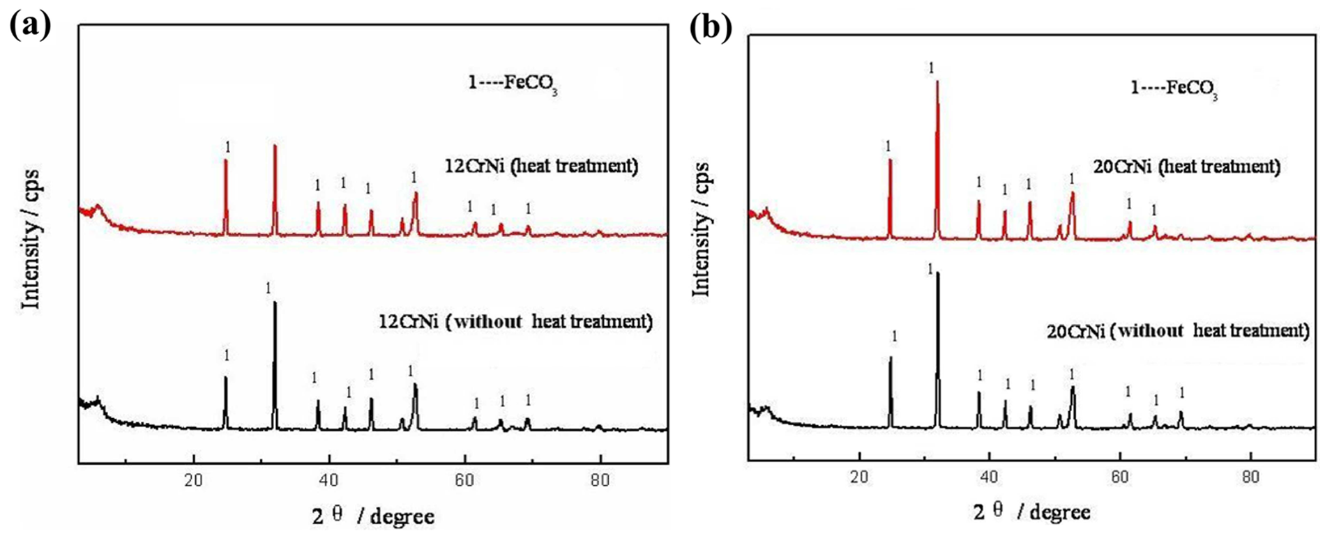
The XRD spectra of corrosion scale formed on the low-Ni alloys steels: (a) 12CrNi; (b) 20CrNi.
Conclusions
The CO2 corrosion behavior of low-Ni alloy steels 08Ni, 12CrNi and 20CrNi, as well as the common gathering pipeline X60 and 16Mn steels, has been well observed and analyzed. Especially, heat treatment was applied to improve the microstructures, mechanical properties and corrosion resistance of the three test low-Ni alloy steels. Several interesting results are summarized as follows.
The microstructures of 08Ni, 12CrNi and 20CrNi low-Ni alloy steels with heat treatment were tempered sorbite phases, while those without heat treatment were the ferrite and pearlite phases.
Based on the values of tension strength (Rm), yield strength (Rt0.5) and impact energy (Akv), the mechanical properties of these specimens were in the sequence as follows: (20CrNi) > (12CrNi) > (08Ni) > 20CrNi >12CrNi > X60 > 08Ni > 16Mn.
The corrosion rates indicated that the low-Ni alloy steels with heat treatment had higher corrosion resistance than those without heat treatment. The corrosion rates were in the sequence as follows: (12CrNi) < 20CrNi < (20CrNi) < 12CrNi < (08Ni) < 08Ni < X60 < 16Mn.
Although remarkable differences exist between the experiments and predicting models, the higher corrosion resistance from the experiments data highlights the dramatic enhancement of Cr and Ni in low-Ni and low-Cr alloy.
Corrosion scale is relatively compact and is well-bonded to the low-Ni alloy steels with heat treatment. In addition, FeCO3 was the main composition of corrosion product formed on the surface of various test materials.
Footnotes
Funding
The Key Laboratory Opening Fund (No. 06A40302) of Corrosion and Protection of Tabular Goods Research Institute of China National Petroleum Corporation is gratefully acknowledged.