
Abstract
An economical 2Cr steel tubing was prepared for application in a certain downhole corrosion condition, and the CO2 corrosion behaviour was investigated by employing the 25Mn2 steel for comparative study. The corrosion films of the two steels under different corrosion conditions were analysed by optical microscope, scanning electron microscope (SEM), energy dispersive spectrometer (EDS) and X-ray diffraction (XRD). It is revealed that the corrosion rate of 25Mn2 steel at static solution is about 2.5 times higher than that at the dynamic solution with the flow velocity of 1 m/s, while the corrosion rate of 2Cr steel keeps almost the same. It is found that both steels show two layers of corrosion film at static corrosion, and the corrosion film is mainly composed of FeCO3, α-FeOOH and dotted Fe3C in the inner layer. It is inferred that carbon pickup phenomenon observed in the corrosion film is attributed to the formation of FeCO3, as well as may also be due to phenomenologically the reaction of Fe3C with carbonic acid.
Introduction
CO2 corrosion is one of the most frequent forms of corrosion in oil and gas production that occurs with high corrosion rates and serious localised corrosion, especially in tubings of carbon steel and low alloyed carbon steel. 1 It has been disclosed that the CO2 corrosion product of steels is mainly composed of FeCO3.2,3 The formation of corrosion film is closely related to the solution pH value, the liquid flow rate, the CO2 partial pressure and the temperature, etc.4,5 FeCO3 corrosion film can form in a static aqueous solution containing CO2 when pH > 4.95 at room temperature, 2 while FeCO3 is the main corrosion product on the steel surface in CO2 saturated aqueous solution with a pH of 6.5. 6 Temperature can affect the corrosion rate and the structure of the corrosion film. At low temperatures (less than 60 °C), the rate of forming a corrosion film on the steel surface increases with increasing temperature, but the corrosion film is considered as unprotective. While at higher temperatures, the corrosion film is faster and easier to form, but is denser and protective. 7 It has been revealed that the outer layer of CO2 corrosion film is mainly of FeCO3, while the inner layer is mainly of FeCO3 and Fe3C. 8 Fe3C is a part of the original steel that accumulates in the corrosion film as Fe matrix corrodes. Like the metal, Fe3C is an electrical conductor. It is proposed that Fe3C acts as a cathode in the corrosion film, 9 increases the cathode area, accelerating the cathodic reaction as well as the corrosion rate. The presence of Fe3C can cause galvanic coupling and the depletion or accumulation of local HCO3−, leading to internal acidification or alkalisation, 10 therefore FeCO3 can not only precipitate on steel, but also directly on Fe3C. In addition, Fe3C can anchor the corrosion film to increase the corrosion resistant to turbulent flow. 11
At present, oil and gas resources are nearing depletion after early exploration, the development of most oil and gas fields has entered the middle or late stage, and the petroleum exploitation of high-temperature and high-pressure deep wells has caused the increase of the CO2 and water levels in oil and gas field. Meanwhile, the widespread application of CO2 injection enhanced oil recovery technology has resulted in a severer corrosion environment for the oil country tubular goods (OCTG) in service,12,13 requiring the application of stainless steel or high alloy steel with high corrosion resistance can well cater for such serious situation, however, the production cost is expensive. The positive effect of Cr element on the improvement of CO2 corrosion resistance has been revealed by many researchers.14,15 And many achievements have been made in the research of carbon steel and Cr-containing steel.16–18 The massive engineering application of 3Cr steel has obtained great success in China owing to the relatively low cost and significantly performance of CO2 corrosion resistance.19,20
According to the practical downhole conditions and the production cost the oilfields can afford, an economical 2Cr steel tubing has been developed for certain corrosion environments. This article presents the research results of simulated downhole corrosion conditions using 25Mn2 and the 2Cr steel in order to provide targeted and guiding basis for the development of new OCTG applied in certain CO2 corrosion conditions.
Experimental procedures
The chemical composition of 25Mn2 steel is mainly composed of 0.25 wt-% C and 1.5 wt-% Mn, while the 2Cr steel is mainly of 0.21 wt-% C, 1.0 wt-% Mn and 2.0 wt.% Cr. The steel tubings were prepared by the following process: piercing–rolling–reeling–sizing. The prepared pipes with dimensions of ⌀177.8 mm × 10.36 mm were then further quenched and tempered to attain the same required 80 kpsi steel strength (N80-Q).
Metallographic samples were cut from the steel tubings, followed by grounding, polishing and etching with 4% nital, and the microstructure was observed with ZEISS AXIO metallographic microscope. For CO2 corrosion test, each four specimens with dimensions of 50 mm × 20 mm × 3 mm were spark cut, and then all the side faces of the specimens were mechanically polished with SiC grit paper before CO2 corrosion test. The weight of three specimens before and after CO2 corrosion test was measured for calculating corrosion weight loss, while the leftover one was prepared for the analysis of corrosion product. The CO2 corrosion test was carried out in an autoclave by using the simulated medium of sodium bicarbonate aqueous solution with the Cl− concentration of 4518 mg L−1, as shown in Table 1.
Composition of corrosion solution.
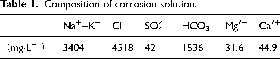
Figure 1 shows the schematics of the structure of the self-made autoclave in the experiment. The specimens of the two steels were placed longitudinally along the plastic flange sleeve nested on steel shaft, which rotated at varied rates to simulate different flow speeds at the specimen circumferential position.
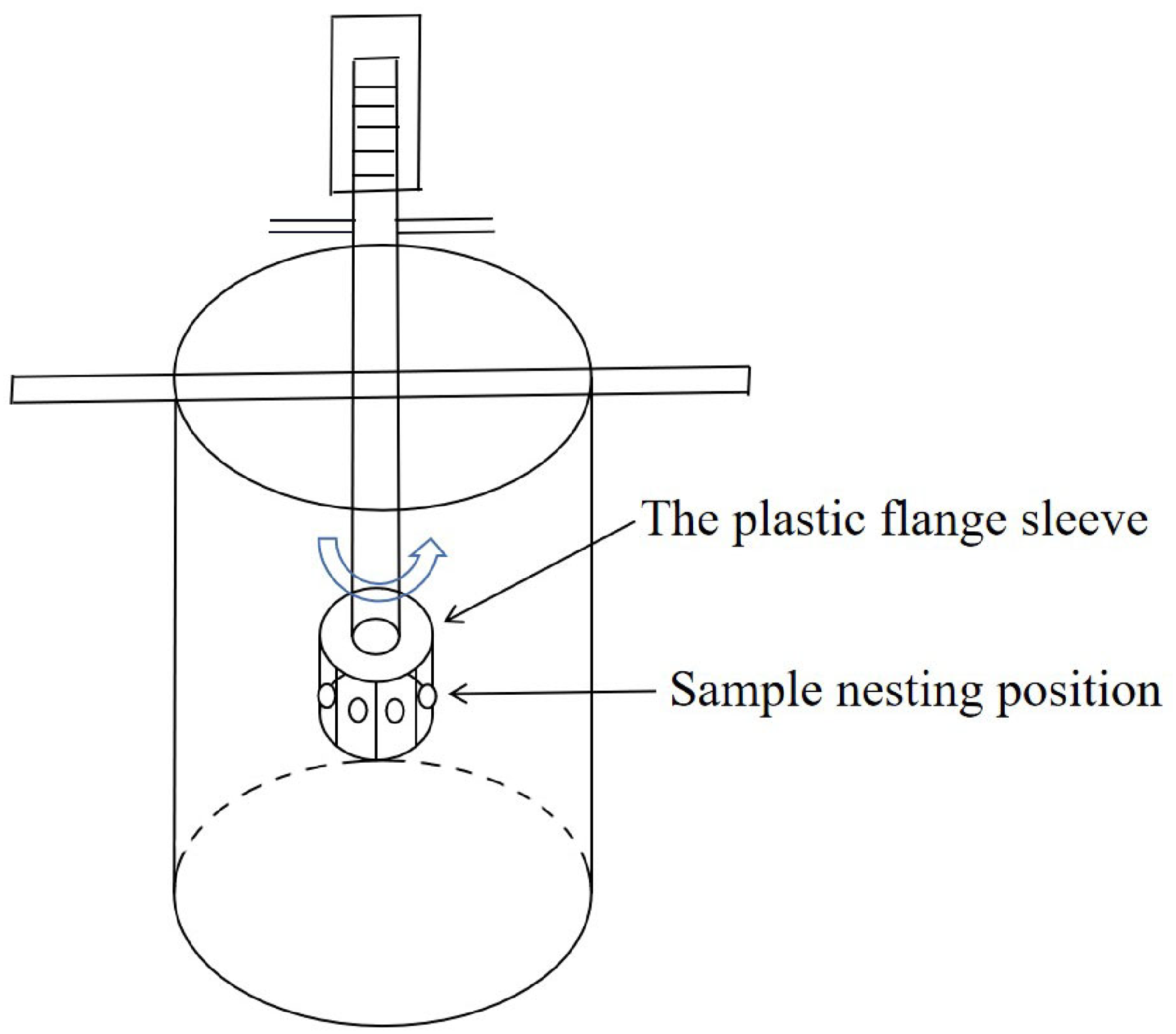
Structural diagram of autoclave.
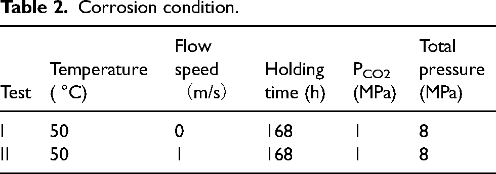
The volume of the autoclave container was 10 L, and the net solution was 8 L after the sample mounting device was inserted. The pH value of the corrosion solution is an important factor that affects the CO2 corrosion rate. 21 The solution was prepared at room temperature and pressure by saturated with CO2 to the initial pH value of 9.01 in order to accelerate the corrosion process. Table 2 shows the corrosion test conditions under a CO2 partial pressure of 1 MPa, Test I corresponds to the static corrosion in order to obtain a complete corrosion film, while Test II simulates the possible downhole conditions with the flow velocity of 1 m/s.
Corrosion condition.
Deoxygenation treatment was performed repeatedly by injecting nitrogen into the autoclave and vacuum pumping before corrosion test. After the corrosion test, it was noted that the pH value of the solution was 6.35 (room temperature and pressure). After taken out of the solution, the specimens of the two steels were immediately washed with distilled water and dried immediately for X-ray diffraction (XRD) analysis. The corrosion products of each three specimens were removed with dilute hydrochloric acid solution (with benzimidazoles as an inhibitor), then after dried and weighed for calculation of the average corrosion rate. And then, a small slice specimen was cut, inlaid and then mechanically polished for cross-sectional observation, it is noted that each above process was followed by ultrasonic cleaning to avoid possible contamination. A Bruker™ D8 Discover system with a Cu Kα target were employed for phase identification under a scanning speed of 8°/min and operating at voltages of 40 kV and 40 mA current. The cross-sectional morphology as well as the chemical composition of the corrosion product film were investigated by a ZEISS SIGMA 500 scanning electron microscope (SEM) and its supporting energy dispersive spectrometer (EDS).
Results
Matrix microstructure
Figure 2 shows the microstructure of the two-steel matrix, which both consist of tempered martensite, that is fine carbide (mainly cementite, Fe3C) is dispersedly distributed on the ferrite matrix, it can be seen that there is no obvious difference between the two steels.
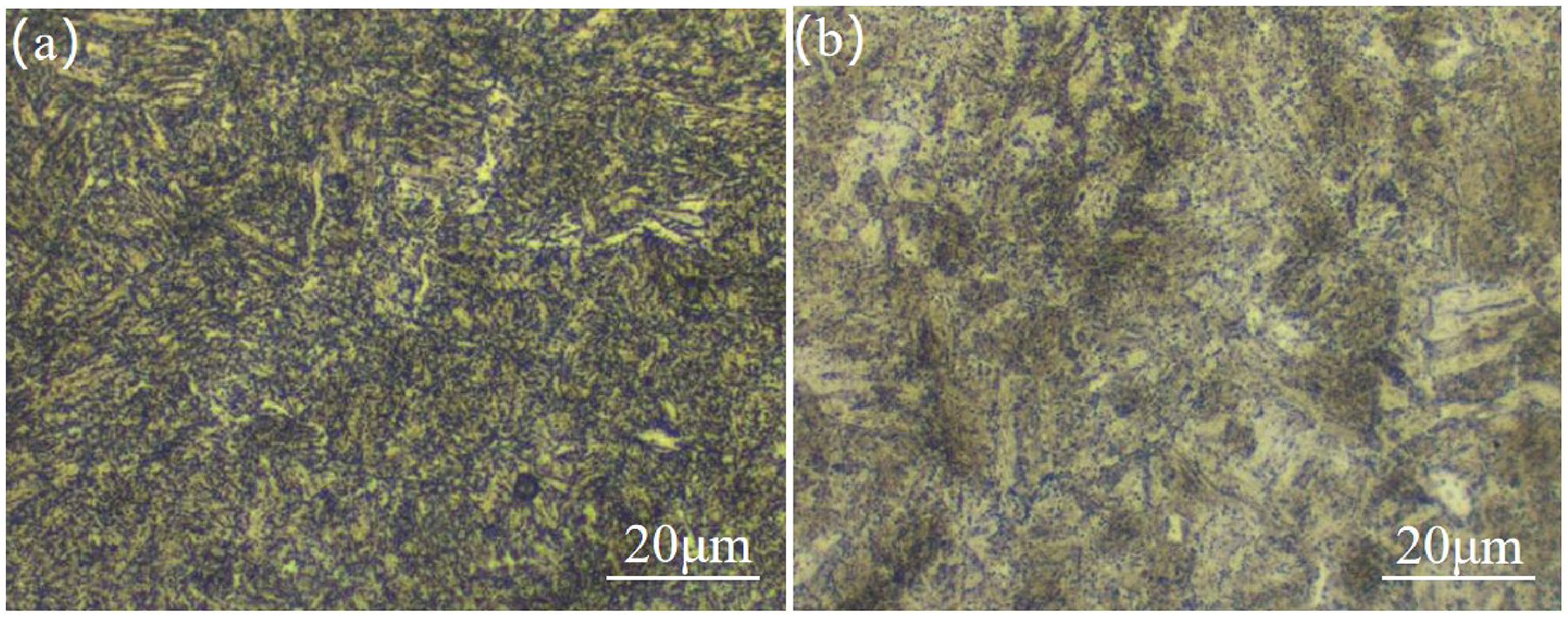
Microstructure of 25Mn2 and 2Cr steels: (a) 25Mn2; (b) 2Cr.
Macroscopic corrosion morphology
Figure 3 shows the corrosion surface morphologies of the two steels with and without corrosion product films under different corrosion conditions. As can be seen, a layer of dark grey corrosion product film homogeneously covered on the surface of the specimens after corrosion test. After the corrosion film is removed, the common 25Mn2 specimen presents typical platform (mesa) morphology characterised by carbon dioxide corrosion, and serious corrosion pits can be clearly identified. While other specimens show uniform corrosion characteristics with a relatively flat surface accompanied by many scattered small pits, indicating the occurrence of similar corrosion pattern.
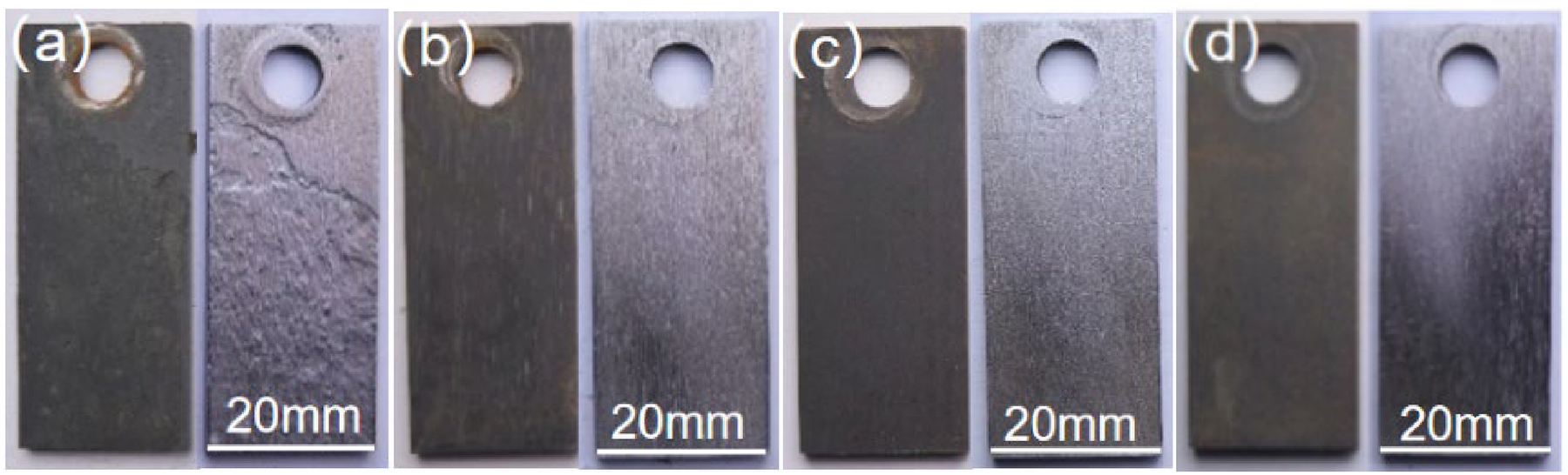
Surface morphology with and without corrosion product films at 50 °C: (a) 25Mn2, 0 m/s; (b) 2Cr, 0 m/s; (c) 25Mn2, 1 m/s; (d) 2Cr, 1 m/s.
Corrosion rate
Figure 4 shows the average corrosion rate of 25Mn2 and 2Cr steels under different corrosion conditions. It can be seen that 25Mn2 steel possesses the highest corrosion rate of 4.91 mm/a at static 50 °C solution, while the corrosion rate of 2Cr steel decreases sharply to 0.99 mm/a under the same corrosion condition. Contrastingly, under the flow velocity of 1 m/s at the same temperature of 50 °C, the corrosion rate of 25Mn2 steel is down to 1.98 mm/a, while that of 2Cr steel has not changed much (1.15 mm/a), and even slightly higher than that at static counterpart. It is concluded that the static corrosion rate of 25Mn2 steel is about 2.5 times higher than that of the dynamic rate, while the static corrosion rate of 2Cr steel is similar to the dynamic corrosion rate at about 1 mm/a. Overall, as an economical choice in comparison with 3Cr steel, 2Cr steel tubing is obviously superior to 25Mn2 suitable to serve under the practical downhole conditions.
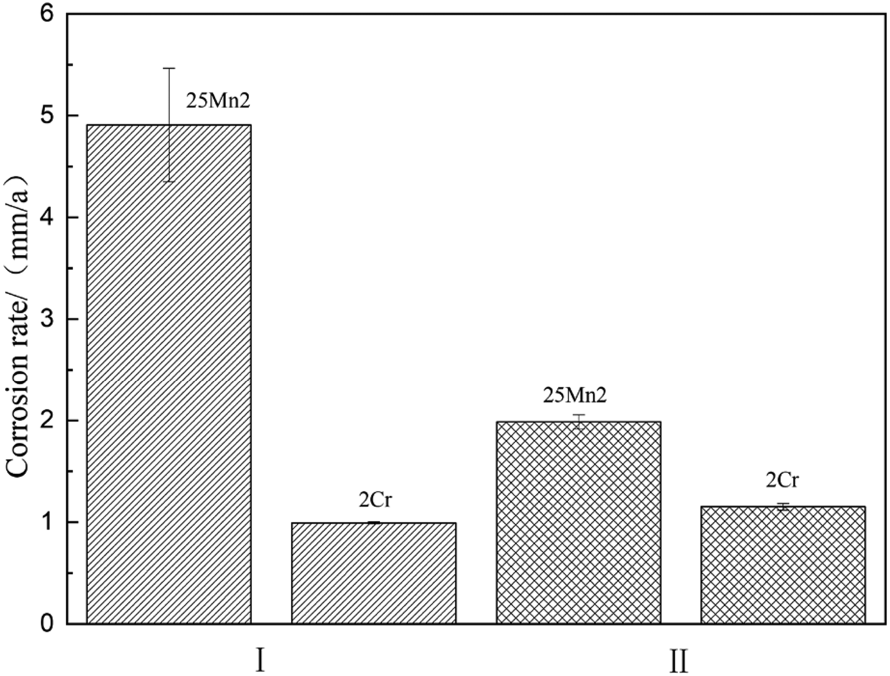
Corrosion rates of 25Mn2 and 2Cr steel under different corrosion conditions.
Phase identification of corrosion product
Figure 5 shows the XRD patterns of the corrosion products of 25Mn2 and 2Cr steels under different corrosion conditions. As shown in Figure 5(a), under the static corrosion condition, the constituent phases of the corrosion film for both steels, 25Mn2 and 2Cr, are mainly of FeCO3 and a small amount of α-FeOOH, and from the XRD peaks it can be seen that the FeCO3 crystal is well developed as the diffraction peaks is sharp and intense, while the α-FeOOH crystalline nature is relatively poor with the characteristic of low and weak peaks. The main orientation of FeCO3 for 25Mn2 steel is (1 0 4), while that for 2Cr steel is (0 1 2), indicating that the addition of alloying element Cr may change the growth orientation of FeCO3 crystal. Figure 5(b) is the XRD pattern under the flow velocity of 1 m/s, the constituent phases of the corrosion film are the same as that of the static condition, it is noted that the matrix iron are also detected owing to the thin thickness of corrosion products. Meanwhile, it is noted that the diffraction peaks of the cementite and graphite appear in the corrosion film with a weak intensity. As the corrosion products are always amorphous or the crystal structure is not perfect, a weak diffraction may also provide the evidence of the graphite presence.
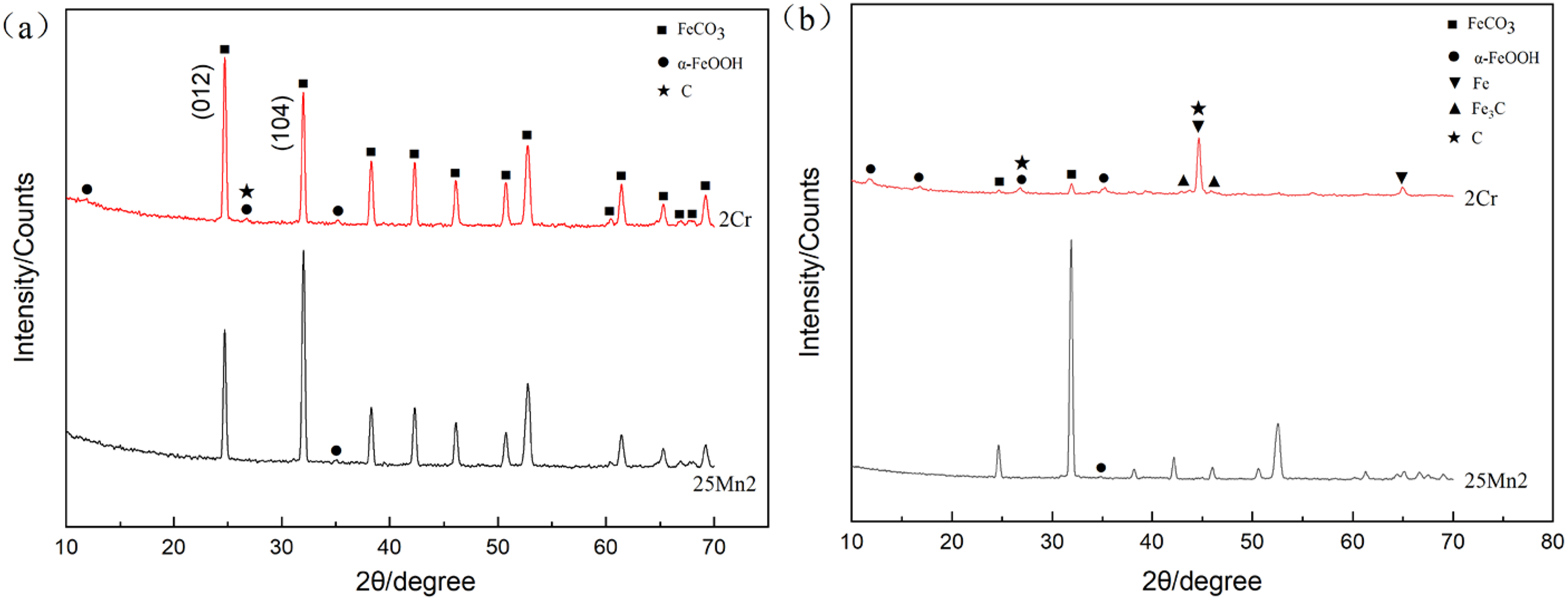
XRD patterns of corrosion films for 25Mn2 and 2Cr steels at 50 °C: (a) 0 m/s and (b) 1 m/s.
Cross-sectional observation of corrosion film
Figure 6 shows the cross-sectional morphology of the corrosion film of the 25Mn2 and 2Cr steels under different corrosion conditions, it can be seen from Figure 6(a) and (b) that the 25Mn2 corrosion film is significantly thicker than that of 2Cr steel under static conditions at 50 °C. The corrosion film thickness of 25Mn2 steel is about 152.7 μm, exhibiting a loose and porous characteristic, while the thickness of the 2Cr steel film is about 41.4 μm, and it is relatively much denser. Both corrosion films show obviously two layers, in which the inner layer interweaves some dark holes on black line boundaries (black arrow) with vast tiny white particles that mostly distribute in the prior austenite grain boundaries (white arrow). According to the constituent of sorbite microstructure, it is obviously that tiny white particles are just the uncorroded Fe3C retained in the matrix once after Fe matrix has been corroded. The outer layer is a pure grey background without the presence of spot-like Fe3C, and the inner and outer layers of the corrosion film are about 130.2 and 19.7 μm for 25Mn2 steel and 29.2 and 10.9 μm for 2Cr steel, respectively.
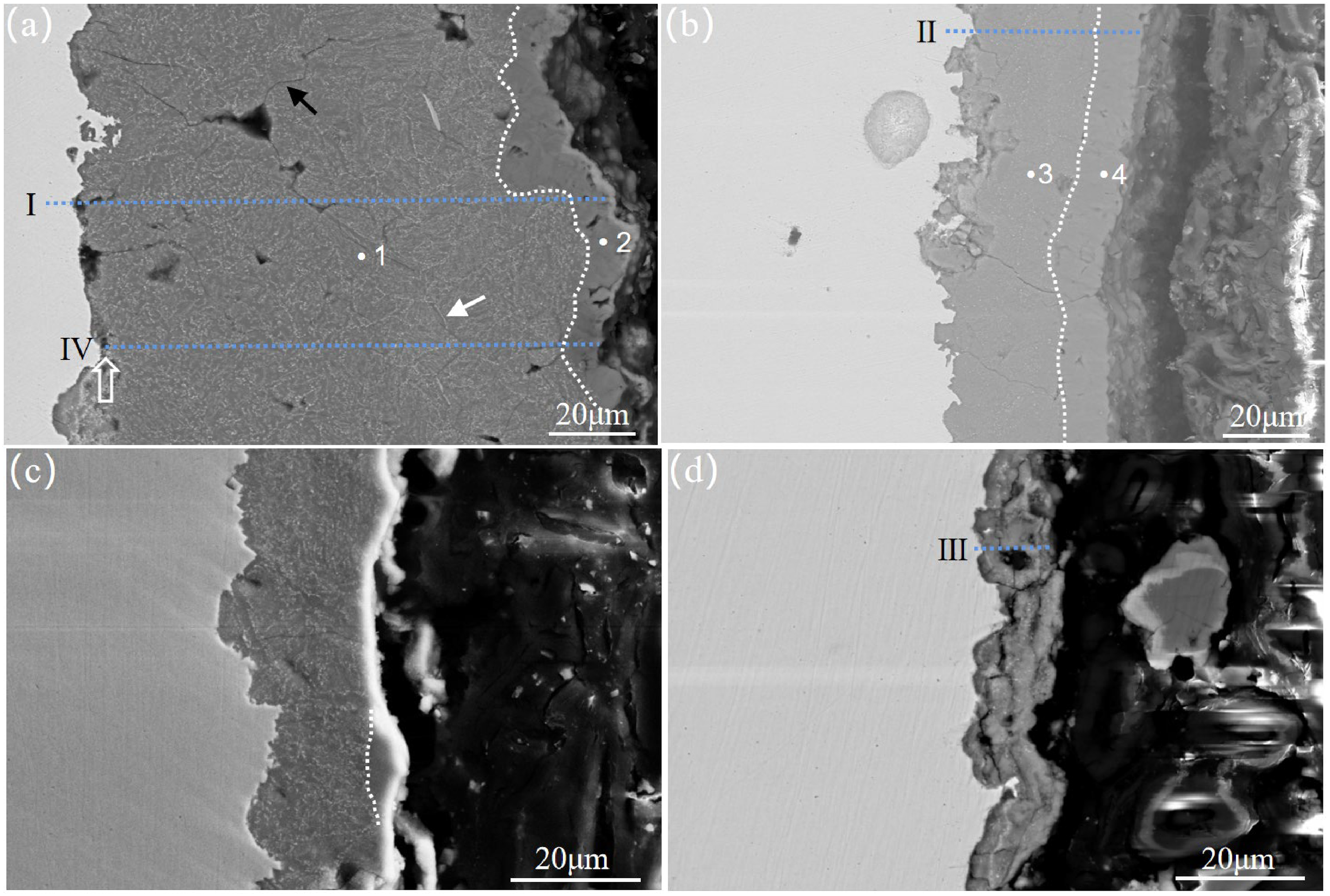
Cross-sectional morphology of corrosion film at 50 °C: (a) 25Mn2, 0 m/s; (b) 2Cr, 0 m/s; (c) 25Mn2, 1 m/s; (d) 2Cr, 1 m/s.
As shown in Figure 6(c) and (d), the thickness of corrosion film decreases significantly owing to solution scouring effect under the dynamic condition at 50 °C, and the thickness of 25Mn2 steel is about 24.5 μm, while that of 2Cr steel is only about 13.1 μm. There still exists a partial residual outer layer in the 25Mn2 corrosion film, while there are obvious cracks in the corrosion film of 2Cr steel and the outer layer appears to be washed off completely, which may account for the non-detection of similar growth orientation of FeCO3 in the XRD profile under the dynamic condition.
Figure 7 shows the composition line scan analysis from inner to outer layers of the corrosion film of 25Mn2 and 2Cr steels. It can be seen from the variation tendency of element distribution, the content of O in the outer layer of the corrosion film increases while the content of Fe decreases in composition with that in the inner layer, meanwhile the Cr enrichment is discriminated in the inner layer of 2Cr steel, according to the effective enhancement of CO2 corrosion resistance in Figure 4, it can safely be deduced that amorphous Cr(OH)3 has been formed in the inner layer.22,23 The content of C near the matrix is significantly increased, which corresponds to the pores of the corrosion film, and the pores and cracks can also be observed in the cross-section image at the pointed arrow (Figure 6(a)). Such sudden change of C element may be due to C contamination at the pores during specimen preparation. However, if the C peak is out of consideration, it is evident that that the overall variation of C content in the inner corrosion product layer is much higher than that in the matrix steel, while the C content carbon in the outer layer is also higher than that in the inner layer and increases significantly close to the edge. The appearance of carbon-rich platform regions in the corrosion product in comparison with the matrix and the increase of C content in the outer layer indicate that the carbon pickup process has occurred.
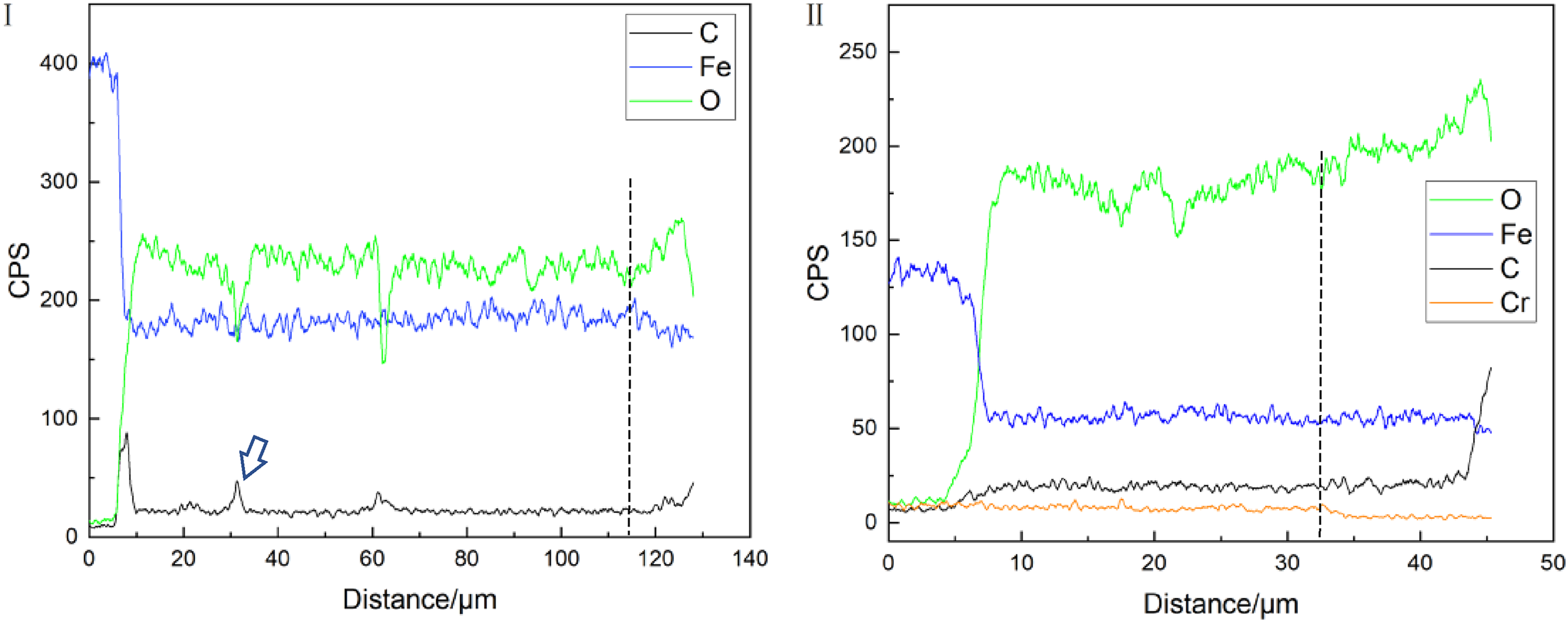
Composition line scans along different positions (the dotted line in the figure is the boundary line between the inner and outer layers), (a) 25Mn2, line I in Figure 6(a); (b) 2Cr, line II in Figure 6(b).
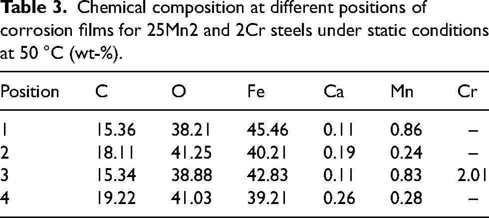
Table 3 shows the EDS chemical composition quantitative analysis at different positions in Figure 6(a) and (b). It can be seen that the content of O and C in the inner layer of the corrosion film of 25Mn2 and 2Cr steel is lower than that in the outer layer, while the content of Fe is higher than that in the outer layer, which are consistent with that of line scans. In addition, it is noted that the Ca element in the solution also participate in the forming process of corrosion film.
Chemical composition at different positions of corrosion films for 25Mn2 and 2Cr steels under static conditions at 50 °C (wt-%).
Discussion
CO2 corrosion is mainly an electrochemical reaction process, and the generally accepted corrosion mechanism is as follows24–27:


Carbon pickup phenomenon
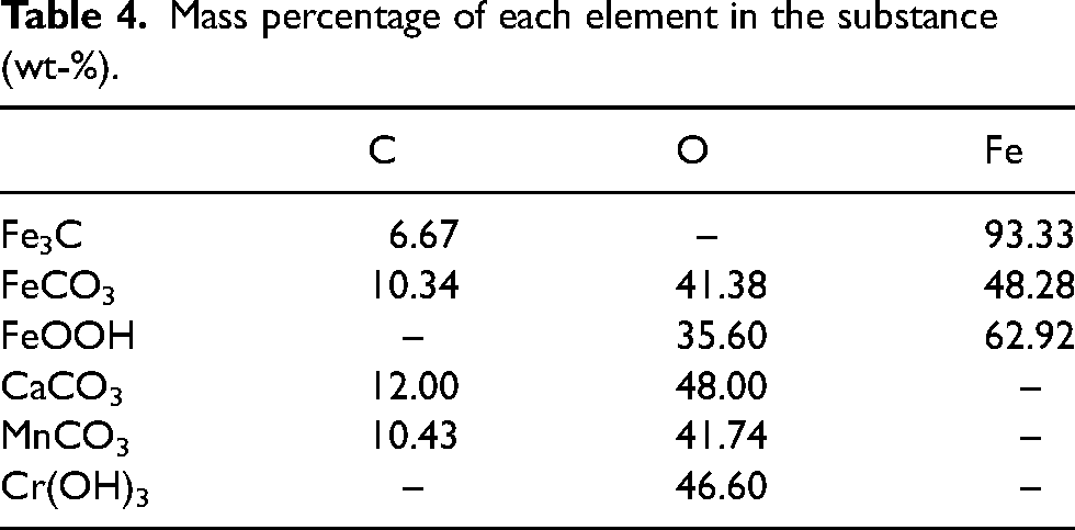
According to the above reaction, it is inferred that the CO2 corrosion is a process of carbon pickup in the corrosion film, which is in accordance to the observation in Figure 7. Table 4 shows the mass percentage of elements in each substance that might be involved in the corrosion process of the two steels according to Table 3. It can be seen that the O content in CaCO3 and Cr(OH)3 is relatively higher, while in FeCO3 and MnCO3 the intermediate level and in FeOOH the less, therefore, the different distribution of these substance in corrosion film regulates the variation tendency of the O and Fe contents from the inner to the outer layer. However, it is noted that the C content of all the compounds is much less than that measured in Table 3. Therefore, the graphite is perceived to be existed according to the above evidence chain.
Mass percentage of each element in the substance (wt-%).
Since the inner layer of the steels is mainly of FeCO3 and Fe3C and α-FeOOH, while the outer layer is of FeCO3 and α-FeOOH, the existence of Fe3C might account for the occurrence of carbon pickup.
Recognition of the role of cementite
It is generally believed that when carbon steel reacts with carbonic acid, the matrix iron Fe will generally generate FeCO3, while the cementite Fe3C acts as the role of cathode to accelerate the corrosion process,28–30 and finally remains in the corrosion products, as shown in the inner layer of Figure 6. However, in the corrosion product film, Fe3C may act as the role of anode and undergo carbon pickup reaction to produce FeCO3 or FeOOH and carbon, the possible reaction formula is as follows:

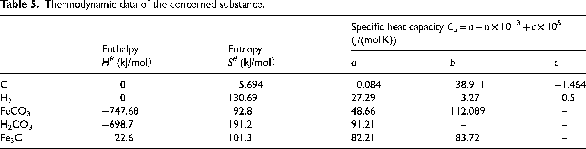
Thermodynamic data of the concerned substance.
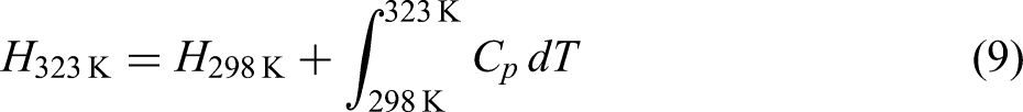
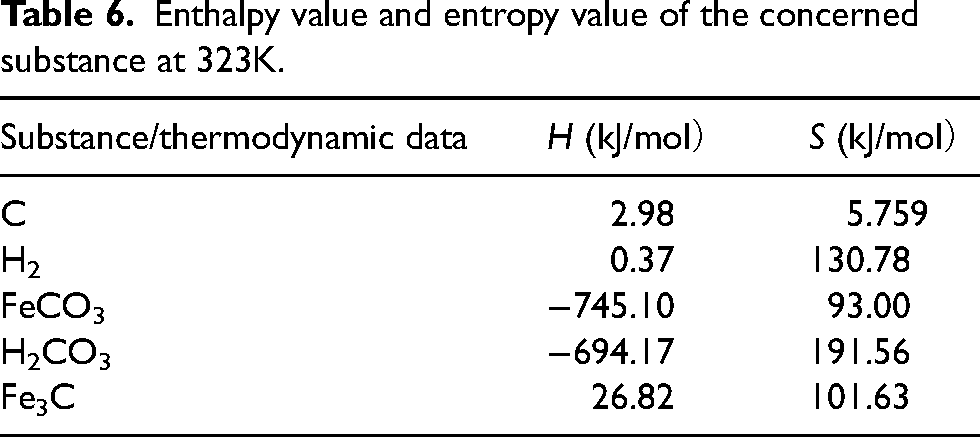
Enthalpy value and entropy value of the concerned substance at 323K.
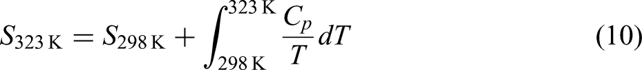
It can be seen that the free energy of Equation (7) at 323 K is

Since Fe matrix acts as large anode and Fe3C acts as small cathode in the substrate, while Fe3C acts as small anode and FeCO3 acts as large cathode in the corrosion film, the possible kinetic process of Equation (8) is shown in Figure 8 schematically. Figure 8(a) presents the process of physisorption, HCO3− in solution is physically absorbed on the anode of Fe3C particles. And then, the process of chemisorption and nucleation occurs under the condition of 50 °C, as shown in Figure 8(b). Fe in the Fe3C particles absorbs the O or OH group in HCO3− so to produce FeOOH and hydrogen, meanwhile the C in Fe3C and HCO3− also precipitates the nucleation of graphite along with it. From the line scans in Figure 7, the C content in the outer layer of 2Cr steel is relatively higher than that of 25Mn2, and the graphite is better developed in the 2Cr steel corrosion film as indicated by the XRD patterns, meaning that the existence of Cr has promoted the precipitation of graphite.
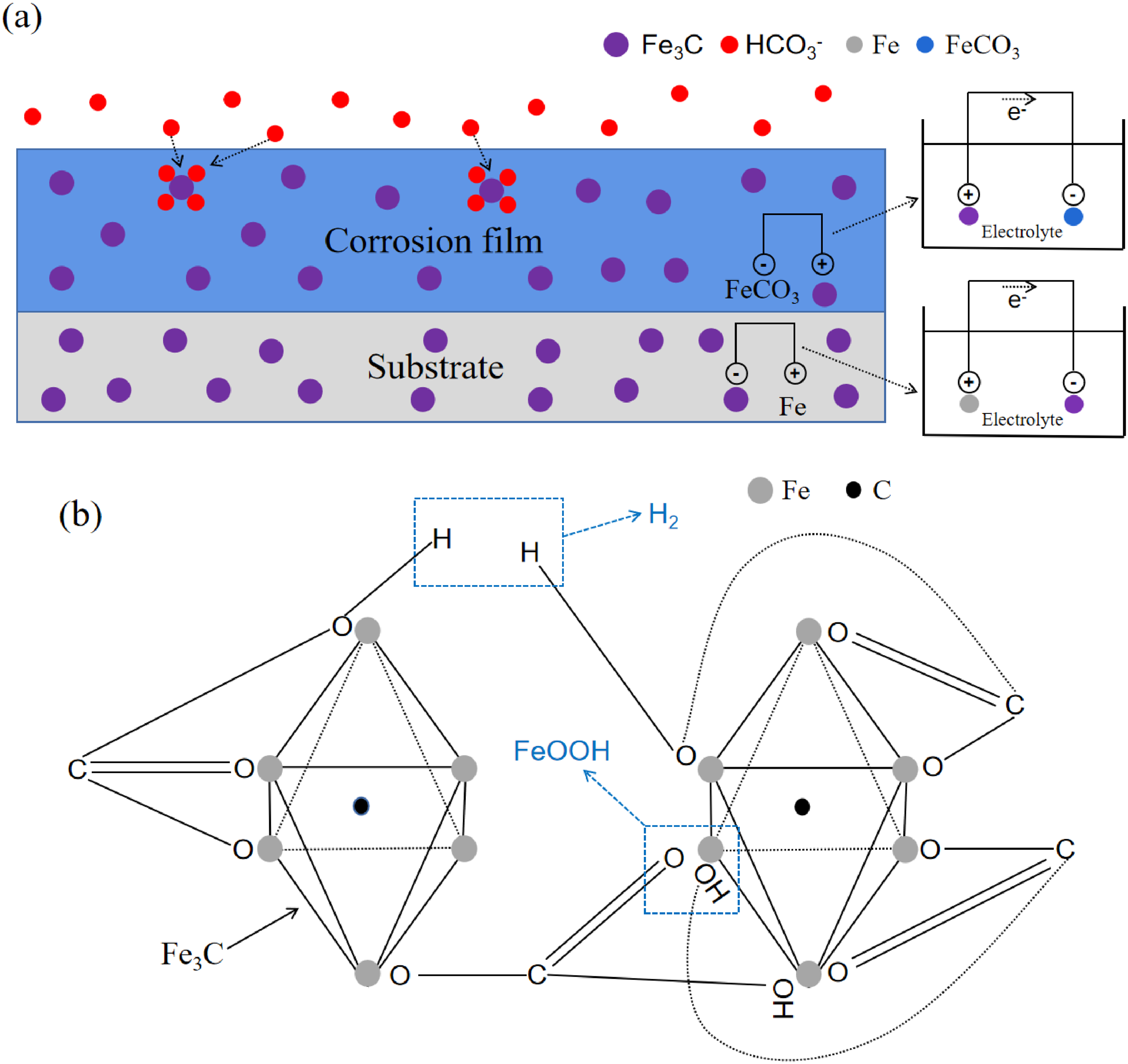
Kinetic process of Equation (8): (a) the process of physisorption; (b) the process of chemisorption and nucleation.
The Cr effect on the reduction of corrosion rate
In the process of carbon dioxide corrosion, when the steel matrix contains Cr, there happens the additional anode reaction
31
:
For the convenience of analysis, Figure 9 represents the variation of Cr and Cl elements corresponding to the line scan positions II and III in Figure 6, it can be seen that the enrichment of Cr in the inner corrosion film of 2Cr steel corresponds to a significant decrease in Cl content (Figure 9(a)), and further enrichment of Cr in the inner layer can more effectively prevent the transfer of Cl ions to the matrix (Figure 9(b)), indicating that the formed Cr(OH)3 corrosion product film has decisive certain cation selectivity, 32 which can effectively prevent anions from penetrating the corrosion product film to the metal surface and reduce the anion concentration at the interface between the film and the metal, and in this way, effectively prevent matrix corrosion.
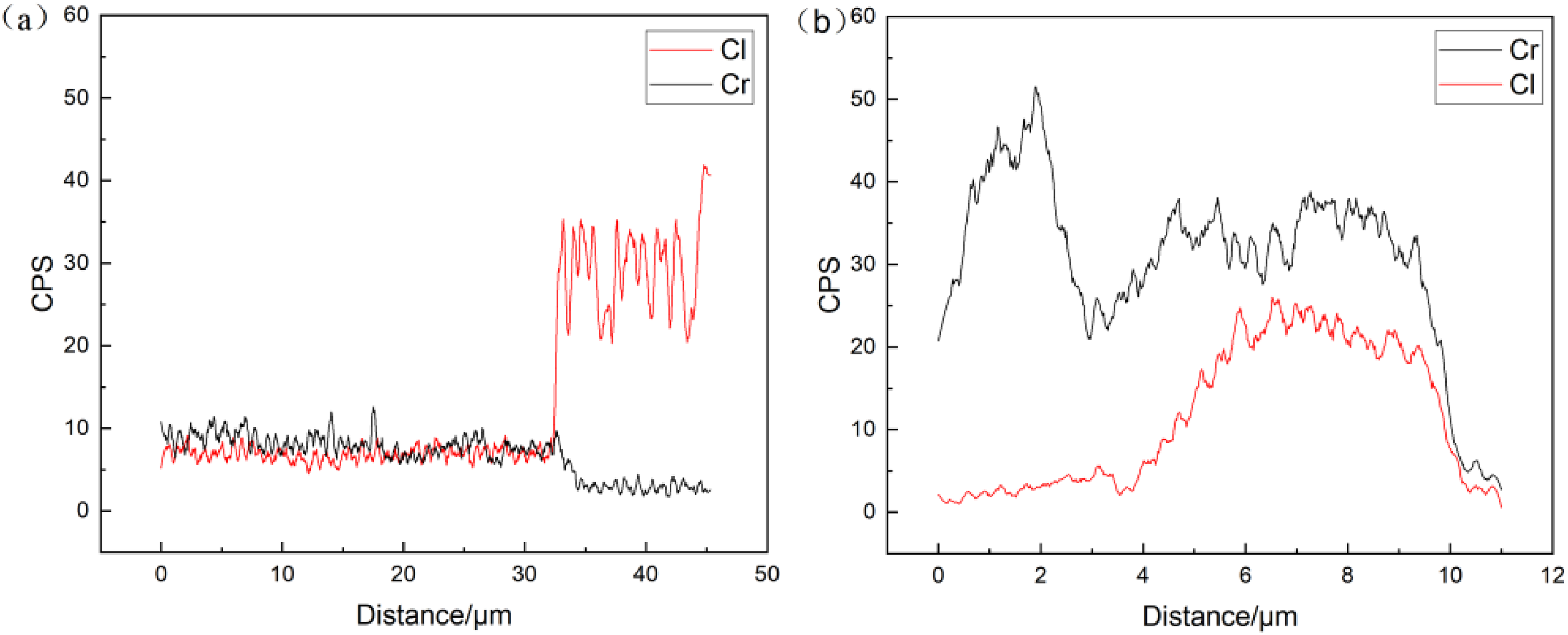
Line scans of Cr and Cl elements along positions in Figure 5: (a) 2Cr, line II in Figure 6(b); (b) 2Cr, line III in Figure 6(d).
Influence of velocity
It is easy to understand that the corrosion rate is higher under the dynamic in comparison with the static corrosion conditions, as is that for 2Cr steel because of scouring effect. However, as for 25Mn2 steel, the static corrosion rate is about 2.5 times higher than that of dynamic corrosion under the flow rate of 1 m/s.
Figure 10 shows the variation trend of Cl− along the position IV in Figure 6(a), it can be seen that Cl− concentration increases significantly at the surface of the corrosion film, while at the interface between the steel matrix and the corrosion film is also obviously enriched, where the point analysis in Figure 10(b) shows that the content of Cl is as high as 3.67%.
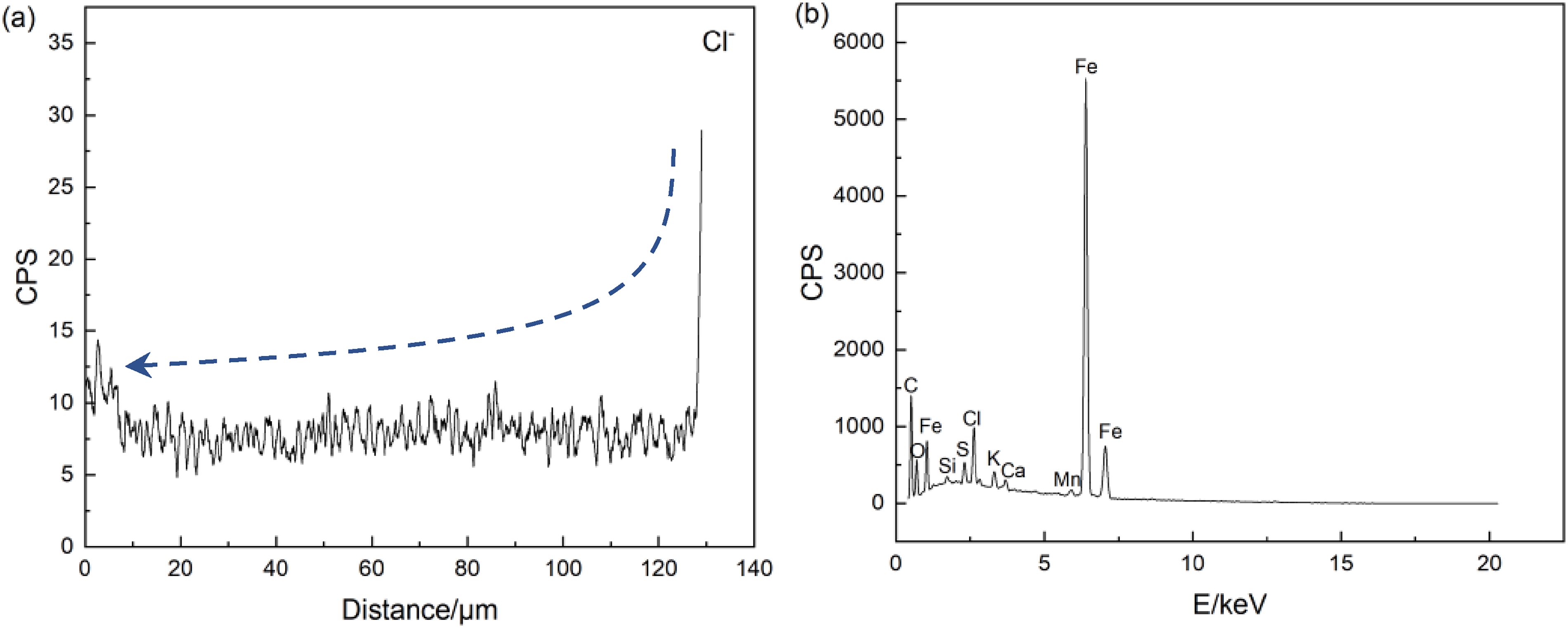
Cl− concentration analysis: (a) line scan Cl− content along position IV in Figure 6(a); (b) EDS pattern at point marked by the arrow in Figures 6(a) and 10a.
Because the 25Mn2 corrosion film is loose and porous, the concentration of Cl− accumulated on the surface of the corrosion product film becomes higher and higher as the corrosion process proceeds under static corrosion conditions, Cl− can diffuse smoothly to the matrix through the passageways in the corrosion film, and thus form a tunnel effect, and therefore effectively accelerate the corrosion process. 33 However, under dynamic conditions, the flow of solution can effectively avoid the occurrence of Cl− enrichment, which is the reason why the corrosion film of 25Mn2 is thicker under static corrosion.
Conclusion
The CO2 corrosion behaviour of 25Mn2 and the 2Cr steels under a certain downhole corrosion condition are concluded as follows:
25Mn2 steel possesses the corrosion rate of 4.91 mm/a at static 50 °C solution, about 2.5 times higher than that of the dynamic solution with the flow velocity of 1 m/s, while the corrosion rate of 2Cr steel keeps at about 1 mm/a under both the static and the same dynamic corrosion. As an economical choice, 2Cr steel tubing is obviously superior to 25Mn2 suitable to serve under the practical downhole conditions. Both steels show two layers of corrosion film at static corrosion. The corrosion film is mainly composed of FeCO3, α-FeOOH and dotted Fe3C in the inner layer, in which enriches with Cr element as for 2Cr steel. The outer layer of corrosion film disappears owing to the solution scouring effect under dynamic corrosion. CO2 corrosion is a process of carbon pickup. The carbon pickup phenomenon observed in the corrosion film is attributed to formation of corrosion product of FeCO3. It is proposed that the carbon pickup may also be due to occurrence of reaction of Fe3C with carbonic acid to produce FeOOH, and the reaction formula is The accumulation of Cr in the form of amorphous Cr(OH)3 in the corrosion film effectively prevents the transfer of Cl− to the matrix. The accumulation of Cl− under static corrosion causes tunnel effect to significantly elevate the corrosion rate. Under dynamic conditions, solution scouring effect is beneficial to prevent the Cl− enrichment from aggravating corrosion.
Footnotes
Declaration of conflicting interests
The authors declared no potential conflicts of interest with respect to the research, authorship and/or publication of this article.
Funding
The authors received no financial support for the research, authorship and/or publication of this article.