
Abstract
The architecture, engineering and construction sector is fragmented, and its computer-aided design systems suffer data loss and errors in workflow between design and realisation. An open source, integrated, modular format is proposed to address the technological nature of these problems. Accordingly, this research updates the notion of the modular format as a more flexible and intelligible computational design method by leveraging knowledge from the computer science and manufacturing sectors where the design and realisation process is intentional and explicit. The research design of this article comprises a theoretical approach combined with an empirical case study. Principles of modularity are extracted from the computer science and manufacturing sectors to assist with a better definition of architecture, engineering and construction computer-aided design processes that use materials and resources more efficiently and sustainably. The methodology of the modular format contributes to the emerging concept of a building lifecycle management system for the architecture, engineering and construction sector.
Introduction
This work is a theoretical and empirical examination of the modular format comprising a review of its development and a case study which advances a new approach. The architecture, engineering and construction (AEC) sector is fragmented, and its computer-aided design (CAD) systems frequently suffer data loss and errors during exchange of files. This fragmentation has also led to cost inefficiencies, poor quality solutions and a tendency for participants to retreat into their own domains.1,2 By contrast, in the manufacturing sector, customers have demanded accuracy, efficiency and reliability fostering the development of complex solid modelling capabilities and fully integrated environments encapsulated by advanced CAD tools, commonly known as product lifecycle management (PLM) systems. Accordingly, the modular format combines the integration of design tools developed by the manufacturing sector with better production techniques, thus providing solutions which can bring the AEC sector into the digital age with its expectations of collaboration, better use of resources and seamless workflows. Management changes, including partnering agreements or integrated project delivery (IPD), would need to occur concurrently with the technological changes introduced by the modular format. As Bock and Linner 3 assert, all aspects of AEC lifecycle workflows including business strategies, modularisation, automation and customer relations have to be coordinated to deliver an integrated and customisable system. However, the focus of this article is the modular format and the refinement of concepts that will improve AEC CAD processes.
Background
A preference for organising parts within the whole can be traced back to Vitruvius’
4
assertion in the 1st-century BC that temple design should be based on the proportions of the human body, a conception in which the part is understood within a hierarchical relationship to the whole. Thus, Mario Carpo describes Vitruvius’ design method, which later influenced Renaissance architects who devised methods of ordering and coordinating parts to ensure that proportional relationships were understood and implemented by the builder: Vitruvius’s design method was based on a proportional modular system, where each modular unit was a constituent part of the building.
5
(pp. 28–29)
Reyner Banham 6 describes a culmination of this approach by Jean-Nicolas-Louis Durand, professor at the École Polytechnique, Paris, France, from 1795, as ‘particulate’, involving a clear identification of parts of buildings which is characteristic of neo-classical architecture. Inadvertently at the time, Durand’s particulate approach laid the foundations for implementation of standardised and modular elements, anticipating the manufacture of industrialised buildings and components. 7
In Vitruvius Redux, 8 Bill Mitchell regarded the singular failing of architectural CAD that it ‘reified these well-established design traditions’, thus limiting the architect’s imagination and, in particular, obscuring the architect’s capacity to read shapes and sub-shapes during the design process. 8 Mitchell 9 suggested the notion of the ‘modular format’ as the antidote to the particulate approach and as a means to improve the intelligibility and flexibility of computational methods in architecture. Nevertheless, this study asserts that the modular format is indeed conceived more effectively as a particulate approach to design. A fuller understanding of the manifestation of modularity in the fields of computer science and manufacturing provides the foundations for this assertion.
For example, Wikberg et al.’s 10 investigation of ‘element-based modular platforms’ is instructive as it describes modularisation as ‘the way a product is decomposed into building blocks (modules) with specific interfaces’. Scheurer 11 also affirms the necessity of defining interfaces, when setting up non-standard projects, a theory built into lean manufacturing processes. Roberston and Ulrichas cited in Wikberg et al. 10 (p. 197) focus on shareability, a feature which enables modules to ‘exhibit high levels of commonality’, while Stehn and Bergstrom 12 note that consideration of modular reusability and shareability can facilitate responses to the upstream flow of engineering and production processes. Concurrently, from the computer science field, Hasselbring 13 (p. 2) described the characteristics and goals of programming modules, including ease of assembly, reusability, flexibility, coupling (of interfaces) and coherence (self-containment).
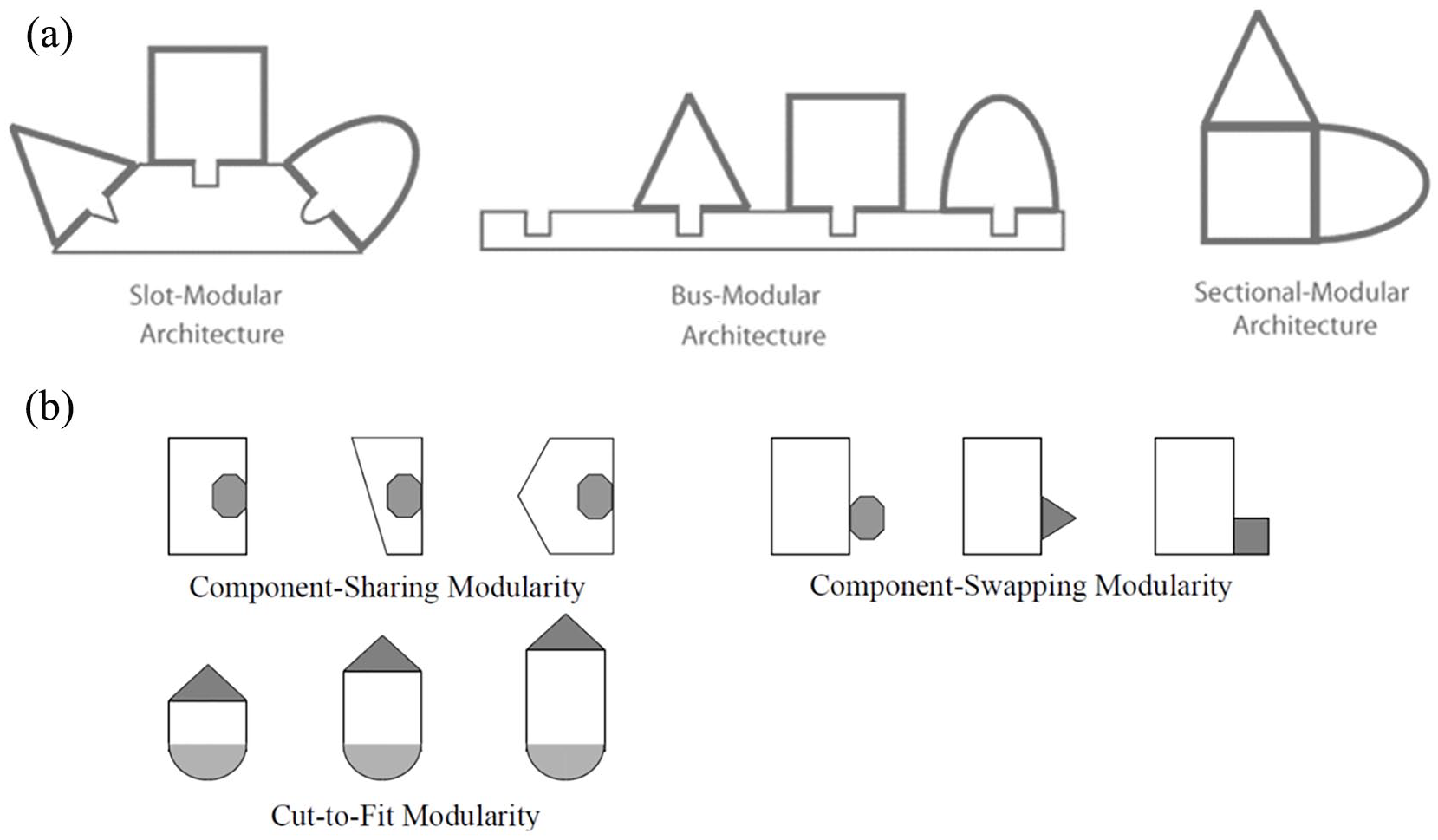
In addition, an advanced understanding of manufacturing sector modularity is provided by Ulrich and Tung 14 who categorised three modular architecture concepts: slot, bus and sectional (Figure 1(a)). Slot modular architecture is examined in the case study. Its sub-categories (Figure 1(b)) may be described in more detail as follows: ‘cut-to-fit’ modularity possesses the property of parameterisation or modifiability where the dimensions of a module can change while its interfaces remain the same; ‘component sharing’ occurs when the same component features in different products; ‘component swapping’ acknowledges that varied components can meet the same interface condition.
Jensen et al.
15
(p. 2) support the notion that product configuration is an effective way to structure modular products that are self-contained and have clear interfaces, while Wikberg et al.
10
call for change to implement: . . . an elaborate definition of the parts that, from a systems perspective and even an industrialised house-building system perspective, support architecture in the built environment.
10
(p. 199)
Only in Japan, due to the unique nature of its housing market, 16 has high levels of modularisation and automation been implemented systemically to improve industrialised house manufacturing. Homes in Japan are considered consumer goods rather than financial investments, and owners expect to ‘scrap and rebuild’ approximately every 26 years 17 (p. 137). Following World War II, their manufacturing industry transformed its approach from mass production to lean production, as developed by Taiichi Ohno at Toyota’s Nagoya car factory. With lean production, products were ‘pulled’ from the factory following placement of the customer’s order, 18 while flexible production lines made different products based on sub-assemblies and parts that arrived ‘just-in-time’. AEC researchers were quick to document these innovations, 19 but slow to recognise the modularisation strategies described above, 2 that facilitate mass customisation of products and foster variety in shape and function, and the reuse and shareability of components.
Toyota transferred its expertise in lean production from the automotive to the housing sector. Toyota Home’s ‘Skeleton and Infill’ system is based on the combination of 10-15 steel frame units to suit the house plan form. 3 Thus, the skeleton is the structural element or chassis subsystem, while the infill comprises the sub-components. Sekisui House, currently the largest of the eight housing manufacturers in Japan 16 (p. 115), was established in 1960 from the housing division of Sekisui Chemical Co. Ltd., also the parent company of Sekisui Heim. By 31 January 2019, Sekisui House had built a total of 2,425,372 houses 20 using an approach to customisation where components and sub-assemblies are organised on site to meet customers’ needs. As part of their integrated and customisable system, Sekisui House developed AUDESEI in 1972, their own in-house automatic drafting and estimation CAD system, which became SIDECS in 1998. 21 In 2008, they merged their customised approach with feature-based modelling using ArchiCAD, parametric modelling using Revit and Building Information Modelling (BIM) techniques, with the aim of making a unified and continuous workflow to reduce repetitive work.
Sekisui Heim, also one of the eight largest housing manufacturers in Japan today 16 (p. 94), combines factory-produced modules – ‘Units’ – to make different house plans. Each ‘Unit’ is unique, made with a steel frame cuboid or volumetric structure, and is part of the Heim Automated Parts Pick-up System (HAPPS) 22 which comprises a seamless workflow from receipt of order to delivery on site. The system’s key innovation is its incorporation of a bill of materials (BOM) with a group of parts identified by ‘menu item master’ (MIM) codes. The MIM codes include many digits which indicate the element (e.g. exterior wall), dimensions, neighbouring parts, interfaces, colour and more. Approximately 4000 MIM codes comprise a house and facilitate just-in-time and in-right-quantity feeding of parts to the assembly line.
These sophisticated examples from Japan are bespoke, closed source, integrated modular systems embedded within PLM systems. Correspondingly in the AEC context, BLM is an emerging theory that addresses the benefits of PLM methods. Several conceptual approaches to BLM have been proposed. Holzer advocates progression from BIM to PLM, 23 while Bonandrini et al. 24 conceive of BLM as a closed source, integrated system similar to PLM. Mangialardi et al. 25 provide a nuanced understanding of the mature structure of PLM and its poor fit to the current state of BIM in the AEC sector. Biccari et al. 26 examine the relevance of configuration views found in PLM systems to BLM. This article advances the proposition that the AEC sector has much to learn from PLM systems. 27 Indeed, the modular format comprises an innovative methodology derived from PLM systems that would be embedded within a new BLM system.
Accordingly, Mitchell’s 9 notion of the modular format is revised as a particulate approach that accounts for these lessons from the manufacturing and industrialised house building sectors and that combines the following interrelated principles: self-containment; well-defined interfaces; reusability, shareability and modifiability; and configurability. The concept of the modular format is enhanced by better understanding of modularity from the fields of computational science and manufacturing where it is an essential condition of components and products. In addition, this article develops the principles of the modular format to advance the concept of open integration of AEC CAD alongside better techniques for making buildings, thus providing a catalyst for change in the AEC sector more generally. This theoretical review which supports the concept of open integration of AEC CAD reinforces the postulation with a case study approach which utilises a closed integrated AEC CAD system to examine the detailed nature of the changes that this postulate demands.
Methodology
An adjunct case study examined a three-storey, 26-apartment development in Brisbane, Australia. This study integrated design and production strategies that combined an advanced CAD system with hybrid prefabrication techniques, including cross-laminated timber (CLT) panelisation and off-site volumetric prefabrication. The project utilised Dassault’s three-dimensional (3D) experience, an advanced CAD system set up on a centrally managed, cloud-based server which enabled participants to communicate remotely via access to a single shared model.
A desktop-based virtual private network (VPN) facilitated navigation of the model, searching for data and files, the loading and launching of applications, and the collaboration between participants. A series of steps defined the design to realisation process of the modular format: setting up of the frame; coordination of data from engineers and suppliers; modular design strategies; and realisation (though not the focus of this study) (Figure 2).
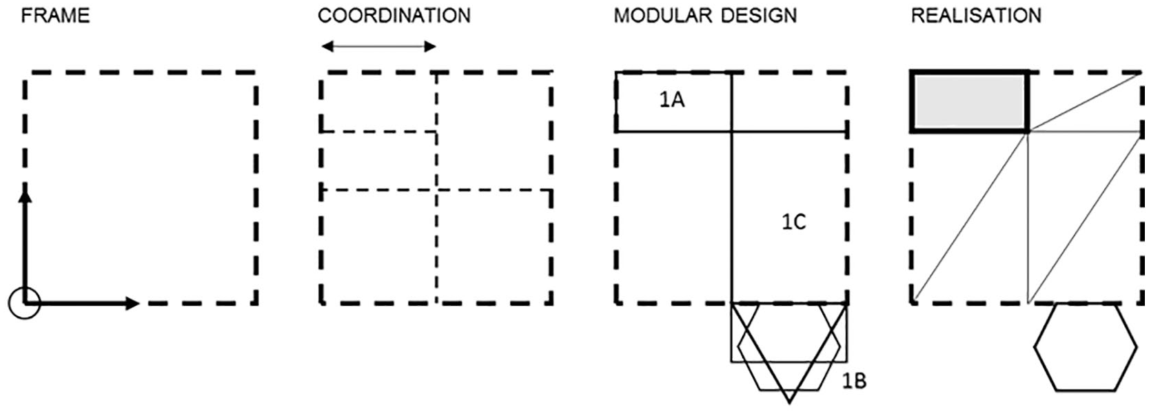
Design to realisation process of the modular format.
Frame
The project began with setting up a framework of variable templates, including the drafting of grids, placement of levels and location of axes in respect to context, and in anticipation of the placement of panellised walls and floors, volumetric bathroom pods and clip-on balconies. Making this spatial framework was a collaborative exercise between participants to determine the points’ precise location and direction, and their relationship with other points and primitives to which parts of the project accreted. This spatial framework defined design intent and presaged realisation as the model developed in complexity (Figure 3).
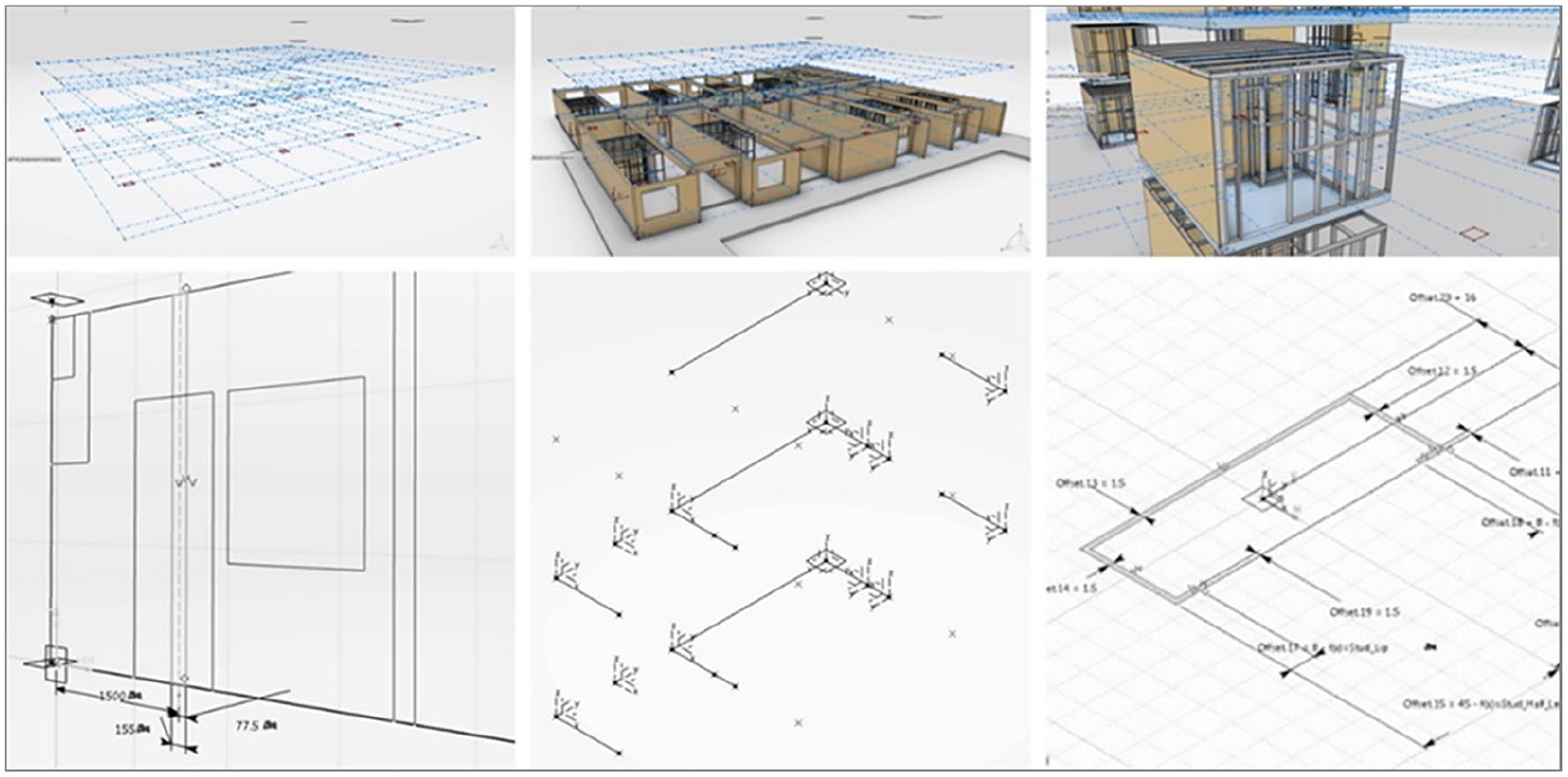
The spatial framework (top-left/middle/right), CLT wall panel template (bottom-left), clip-on-balcony template (bottom-middle) and light gauge steel (LGS) stud part (bottom-right).
These variable templates were explicitly modelled to allow complexity to emerge by investing them with comprehensive parametric properties. Spatial location was precisely defined based on spatial orientation and the relationship of parts to each other. The process captured predictions of future changes and included automated representations for realisation of the project. Parameters defined as ‘features’ were constrained by associations and were also used as the arguments of relations. User parameters were defined at product (assembly), shape (3D framework construction) and feature (part) levels. Two-dimensional (2D) wireframe elements were used to create 3D features using reference planes to support sketches, while the planes’ positioning defined origins and orientations.
Coordination
The advanced CAD’s user interface (UI) gave access to approximately 130 apps, including those for ‘3D Modelling’, ‘Social and Collaborative’ and ‘Information Intelligence’. All apps were viewed and launched from the ‘Dashboard’, the collaborative workspace of the corporate UI. At project level, a hierarchical UI defined a model shared by participants which was driven by a tree-like visual display of its internal structure. Close collaboration with engineers was supported by simulation apps for structural analysis and computational fluid dynamic (CFD) analysis, although these were not used in this project. A single shared model contained complex parametric and scripted knowledge, made accessible by the hierarchical tree of relationships which allowed reuse of each other’s model files.
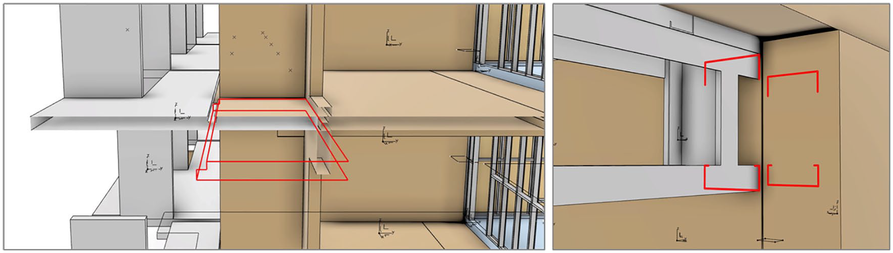
The dimensional and structural properties of CLT panels had been analysed by structural engineers and suppliers during the schematic design stage, enabling setting up of the frame, coordination and modular design to progress with confidence (Figure 4). Therefore, maximum length, width, thickness dimensions and spanning direction of the CLT, as well as the coordinating requirements for glulam infill and support beams, were all considered early during the schematic design stage. Thus, the upstream flow of data had reached the researchers in a timely manner; this, in turn, enabled setting up of the frame, coordination and modular design steps to progress with confidence.
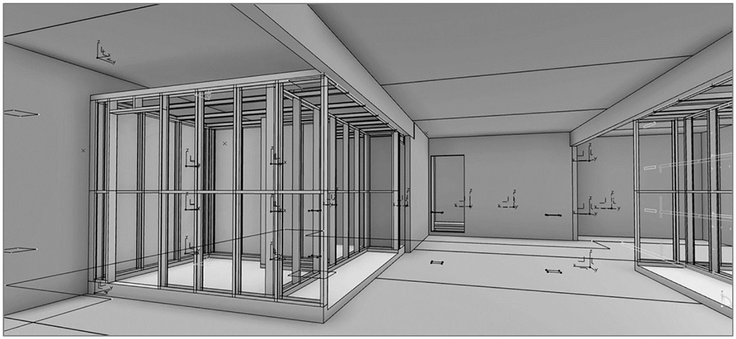
Coordination between CLT wall/floor panels and LGS pods.
Coordination of complex modular relationships used advanced CAD instruments that monitored the status of component accuracy and location in relation to other components. For example, ‘Check’ informed the user whether specified conditions were fulfilled. This was first defined in non-programming language as follows – ‘Check that the rebate depth parameter is less than or equal to the wall thicknesses’. In addition, the ‘Rule’ feature facilitated variations to modules by controlling relationships between parameters. For example, the CLT wall panel’s notches, openings and rebates were activated or deactivated by a file associated with the panel’s location.
Automation was implemented using ‘Knowledgeware’ which embedded ‘intelligence’ into the project. Imperative scripting used Engineering Knowledge Language (EKL) which enabled definition of associative rules to drive parameter propagation and facilitated the transformation and instantiation of objects using ‘Engineering Templates’ (assembly level), ‘PowerCopies’ (part level) and user-defined features (UDFs; at part level).
Visual coordination of parts and components relied on a clear perception of self-contained objects. This ensured that relationships, and types of components and materials could be quickly checked. But a more thorough understanding of coordination was provided by ‘Interference Simulation’ which analysed all clashes and produced a spreadsheet indicating each individual clash detected (Figure 5).
‘Interference Simulation’: clash detection for all components and parts of the model.
Modular design principles
The slot modularity principle of cut-to-fit 14 was applied to panel templates where parametric variations allowed manipulation of dimensions. Interfaces were also parametrically defined to create butt and alternate overlapping joints. For this project, 36 parameters defined the condition of all wall panels including notches, rebates and openings, but potentially enabling extensive variability. The panels’ location, length and height were determined by directional axes and insertion points related to the whole assembly (Figure 6). A floor panel template was created in a similar manner.
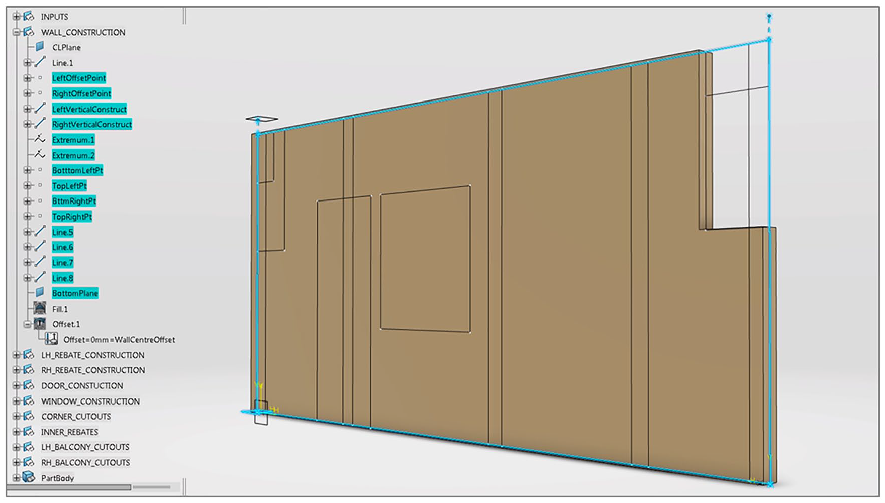
Cut-to-fit: wall panel template parameters × 36 and ‘Rule’ (Graham Day, University of Sydney).
Component sharing principles were incorporated by the bathroom pod where its common interfaces abutted variable wall and floor panel configurations. EKL was used to automate light gauge steel (LGS) stud placement in the volumetric bathroom pods’ wall panels. This used logical names associated with the model’s parameters for looping through lists of new components to be extruded from templates and instantiated at precise locations in the reference frame. Thus, component modelling, which is common to conventional CAD packages, did not occur (Figure 7).
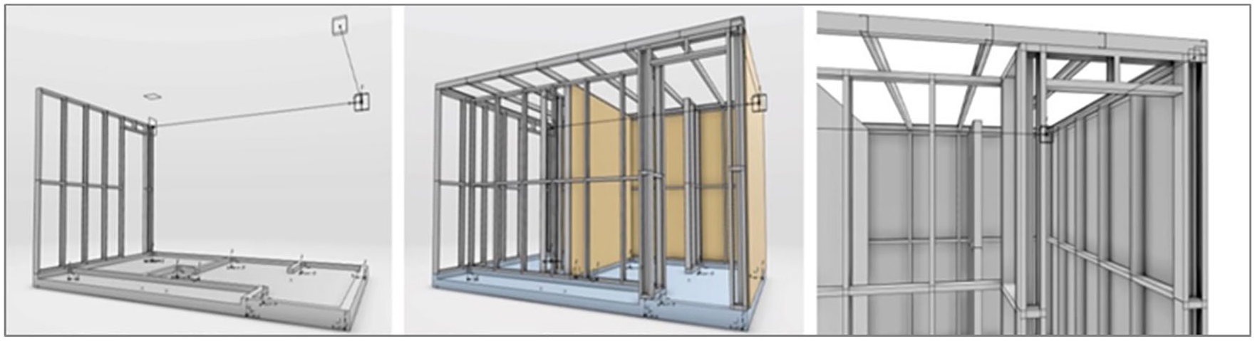
Component sharing: LGS stud placement and volumetric pod assembly.
Component swapping was implemented to create four different types of clip-on balconies whose interfaces with the floor and wall panels were similar. Configurations of clip-on-balcony components were made using spreadsheets. Variations were initially defined in a ‘Design Table’ containing the parameter values of a model file. Then, a ‘Component Family’ was created to provide pre-defined sets of configurations of the wall or floor component that differed with respect to their parameter values. These were incorporated into a ‘Product Table’ at assembly level to capture configurations of the four different balcony types (Figure 8).
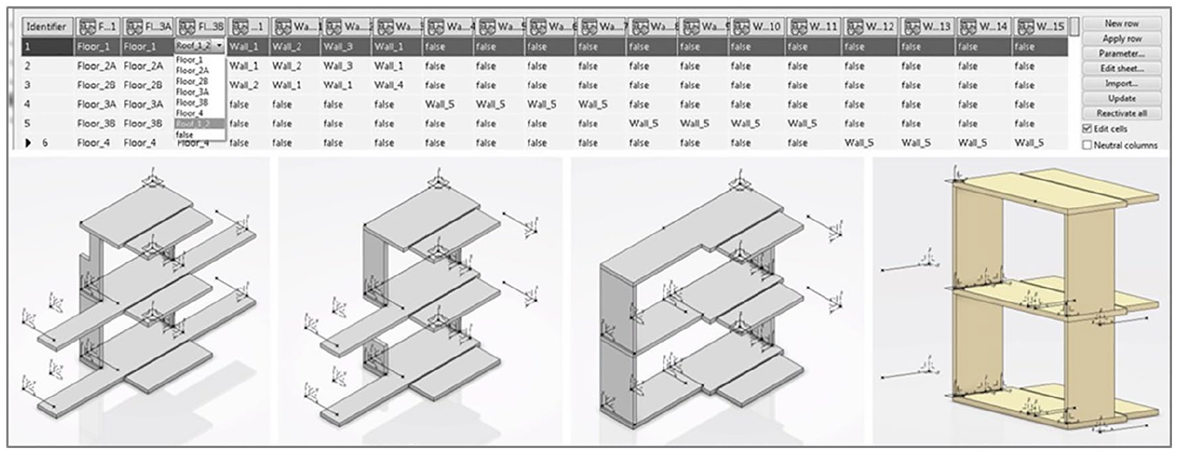
Component swapping: design table and component family (top), and product table (bottom).
Findings
Frame
During setting up of the frame, this study confirmed that the modelling environment accurately replicated both on- and off-site assembly processes where precise spatial understanding is required to locate objects. Formalisation of this understanding also enabled drafting tasks to be semi-automated at the cost of extra effort and collaboration between participants. Setting up of the spatial framework was the foundation which facilitated modelling of the modular format principles.
Drafting
Pre-planning the framework also significantly reduced the drafting load because only a small number of 2D sketches were needed to define parametric relationships capable of generating many alternative 3D modelling solutions, while the parameters themselves were accessible and controlled from a hierarchical tree. Parameters were described as features that can be constrained by relations and can also be used as the arguments of a relation. In this case, ‘user parameters’ were created to allow immediate access to the parameters that pilot geometry and to centralise information that a new user can easily use. User parameters were defined at the product (assembly), shape (3D framework construction) or feature (part) level. For example, as noted in section ‘Methodology’, assembly of the wall panels within the model used a template with 36 user parameters created for the whole project, which allowed for all variations of wall panels. This emphasised that the main task, rather than the task of drafting, was to associate these templates with directional axes, locations and planes within the frame created.
Wireframe
The visualisation and cognitive challenges of advanced CAD differed markedly compared with AEC CAD: in the latter, wireframe setup is hidden, thus masking parametric relationships from the user but making early design workflow quicker. However, with advanced CAD, early investment of time and effort benefitted future decision-making because solutions were intentionally and explicitly shaped with inherent flexibility and modifiability in mind.
Coordination
The project was organised more holistically than conventional AEC CAD projects because the shared UI facilitated full coordination of technical and management processes, while a single shared model allowed participants to contribute according to the roles assigned to them. Corporate, project and model UIs were comprehensive and provided clear visual and conceptual understanding of workflow, progress and goals while remaining open and accessible to all participants.
The advanced CAD models’ high levels of interoperability resulted from hierarchical methods used to define parametric relationships and from rigorous sharing protocols which facilitated access to files and documents, thus avoiding concurrent access issues. Concurrent access to documents was managed by the ‘Collaboration and Approvals’ app, which defined the lifecycle state of the document via its maturity level and via the ability to ‘check in’ or ‘check out’ the document. For example, in the ‘Private’ state, the document was accessible by the owner only; in the ‘In Work’ state, on the contrary, the document could be modified, a new revision created or it could be demoted by the owner to the ‘Private’ state. If ‘Frozen’, the document would be under review; if ‘Released’, it would be available for production and delivery. When no longer in use, the document was promoted to the ‘Obsolete’ state. ‘Check-out’ enabled the document to be downloaded from the cloud to the PC when the document was locked for independent working. With ‘Upload/Check-in’, a new version of the document was automatically created. It was also possible to ‘Reserve’ a document, thus activating a green key icon that indicated owner access or a red key icon that indicated that non-owners were prevented access. In short, to safeguard the documents, the system managed and kept track of all states and of checked-in and checked-out versions.
Automated checks, rules and interference simulations fostered refinement of the modular format principles implemented, while clarity of representation of the distinct modules and assemblies assisted visual coordination and checking. Early collaboration by the participants in setting up the spatial framework ensured effective shareability and modifiability during the parametric manipulations which followed between the wall and floor panels, volumetric pods and clip-on balconies. Interoperability between these parametric models and their scripted links was robust and stood up to constant flexing and changes. In addition, automated rules and checks facilitated monitoring of parametric modifications.
In summary, knowledge captured by EKL scripting demonstrated a robust ability to link parametric modules – stud (part), wall panel (part), volumetric pod (sub-assembly) and building framework (assembly) – in a complex hierarchical whole. This process maximised the productivity of repetitive tasks because intelligence or knowledge was captured as formulas, rules, checks and knowledge patterns within the hierarchical tree of parametric models. These features also facilitated reuse and sharing of parts and assemblies. Design Tables, Component Tables and Product Tables facilitated configuration of modules in the form of spreadsheets. These provided a familiar and easy-to-use parametric technique which increased productivity by simplifying accessibility and visualisation of parametric associations between parts and assemblies. Model instances could be enabled or disabled via the spreadsheets, allowing efficient reuse of assemblies and ease of modification of their parameters.
Modular format
The principles of the modular format utilised in the case study assisted with the setting up of wall and floor panels, volumetric bathroom pods and clip-on balconies. Slot modularity principles enabled modules to be conceived of and to embody self-containment, well-defined interfaces, reusability, shareability, modifiability and configurability. Advanced CAD’s inherent hierarchical structuring of parts and assemblies enhanced implementation of these principles.
Slot modularity cut-to-fit principles were expressed as parametric variations of the modules’ panel size. The interfaces were also parametrically variable as they allowed for butt, and alternate, overlapping joints. The wall panel template with 36 parameters defined the condition of wall panels by taking account of notches, rebates and openings, while the panels’ location, length and height were determined by directional axes and insertion points related to the whole assembly. A floor template was also created in a similar way, with user parameters to control features, and axes and insertion points to determine location. Each instantiated object, wall or floor in a specific location was automatically linked to a drawing output providing data for cutting and machining the CLT panels, while the CLT panel dimensions were restricted by the material’s maximum length and height dimensions and by the cutting machine’s extents.
Slot modularity component sharing principles were applied to bathroom pods which had the same layout for each residential unit, although the immediate context of surrounding wall and floor panels varied. The programming language EKL was used to automate LGS stud placement in the wall panels of the volumetric bathroom pods. Syntax used logical names associated with the model’s parameters and geometry, and enabled lists to be looped through and new components to be instantiated at precise locations in the reference frame. The EKL script associated stud (part) with wall panel (part), with volumetric pod (sub-assembly), with building framework (assembly), thus demonstrating a rigorous and robust ability to parametrically link part to part in a complex hierarchical whole.
Slot modularity component swapping principles defined four different types of clip-on balcony, each meeting the main building’s floor panels and external wall facades in similar ways. Their varied components met the same interface condition, while variation was created and managed using configuration applications common to the manufacturing sector and advanced CAD.
Section ‘Findings’ demonstrates that advanced CAD has features capable of capturing knowledge and integrating this with fully parametric entities developed in a holistically collaborative environment according to modular design principles, a combination which encapsulates this revised version of the modular format.
Reflection
Knowledge capture
Among architects there is hardly a single universalised workflow, and knowledge passes down primarily through people rather than encapsulation in software.
28
(p. 41)
This research confirms that tools and methods already exist that can assist the AEC design and production process by replacing tacit workflows with holistic solutions that capture design knowledge. In the manual and automatic processes of knowledge capture lies the mode of intelligence that architects have wished their computational assistants to possess. Today, with the addition of algorithms that can learn from such knowledge, the architect now has an assistant who can predict better outcomes as well. As the review of Japanese housing manufacturers confirms, knowledge capture is already part of a sophisticated technique implemented by Sekisui Heim with their MIM codes.
Well-formedness
The property of ‘well-formedness’, as Yehuda Kalay 29 remarks, guarantees that the ‘representation will always correspond to the shape it represents’. This enables the architect and the engineer to quantify and evaluate the properties of objects with confidence. It is contended here that wireframe primitives used to set up the spatial framework liberated rather than constrained the design process by enabling intentionally defined variety and explicitly modelled flexibility to be captured, thus fostering the likelihood that shape and representation would indeed concur.
Concept to development
Establishment of interactions and interoperability between parts and assemblies replaced the ubiquitous arrangement of ‘out-of-the-box’ component modelling common to AEC CAD, a process itself only abstractly related to the particulate approach criticised by Mitchell. 9 Intentional composition combined with explicit expression characterises the nature of modelling with advanced CAD which echoes Carpo’s 5 intimation of digital tools: ‘craft-like propensities recalling preindustrial artisanal practices’.
However, advanced CAD interprets design intent reductively rather than in an open and exploratory way. Hence, a conceptual model, a hand-drawn sketch or a virtual reality inspired spatial sequence would transition with difficulty to this rigorous and logical mode, a weakness to be addressed should architects be encouraged to fully engage with these tools.
An open integrated system and building lifecycle management
Advanced CAD systems are open to participants by subscription only, whereas the AEC sector’s CAD tools have mostly been developed as open source applications. The Japanese examples reviewed – Sekisui Heim, Sekisui House and Toyota Home – demonstrate powerful and effective examples of closed source integrated CAD systems which are embedded in a PLM system. But these, and the advanced CAD alternatives discussed, are presently the only fully integrated options available. However, openness and collaboration are a strength because they allow for a wider testing of ideas and foster collective understanding. Hence, there is a need for ‘open integrated systems’ for the AEC sector, as noted by Schodek et al.: Vendor-specific integrated systems clearly share the disadvantage that seamless integration, if at all, exists only within these closed, proprietary environments. A need for open integrated systems is identifiable.
30
(p. 233)
This article’s empirical approach has enabled closer examination of these PLM methods during implementation of an AEC project. The modular format has advanced building lifecycle management (BLM) theory by proposing an open source, integrated, computational design methodology which progresses from the frame, to coordination, to modular design and to realisation. This will form the foundation of a new methodology and a new technology that will integrate the AEC sectors’ building lifecycle stages.
Ambiguous plus unambiguous design
Advanced CAD designs parts and assemblies in an unambiguous manner, while AEC CAD models only partial representations of a design’s final form. This is succinctly explained by the difference between ‘solid’ and ‘component’ modelling, respectively: solid models include the volume contained within bounding surfaces, while component models are polygon meshes which facilitate visualisation and rendering but include no volumetric properties. 30 Ambiguity may be desirable in the early stages of architectural design, but during the development stage unambiguous representations provide reassurance that the goals of the design intent will be met. A smooth transition in workflow between these two representations is needed.
Conclusion
This article re-examined and updated the notion of the modular format initially suggested by Mitchell 9 (p. 8) as a means to improve the flexibility and intelligibility of computational design methods. The updated notion of the modular format now incorporates principles from the manufacturing and computer science fields where modularity embodies self-containment, well-defined interfaces, reusability, shareability, modifiability and configurability. These principles have been empirically demonstrated by a case study which incorporated them into computational design processes and more efficient and sustainable techniques for designing and making buildings.
Encapsulating these principles within the modular format offers solutions to technological problems caused by the fragmentation of the AEC sector, problems which have led to inefficiencies, wasted resources, data loss and errors in AEC CAD workflows. Its take-up by the AEC sector would require the re-organisation of these workflows to precipitate the availability of suppliers’ information and would necessitate changed contractual relationships between participants. AEC CAD has moved beyond the notion that point, line and surface are fundamental elements of a particulate approach to design, as espoused by Vitruvius and reified by Renaissance architects. Instead, placement of ‘out-of-the-box’ components and a library of parts has become the norm to the extent that the principles which define them and their relationship to the realisation of built outcomes are unknown. In contrast, the updated modular format makes these principles and their realisation intentional while capturing knowledge, the source of intelligent evaluations, in an explicit rather than a tacit way.
Footnotes
Acknowledgements
This case study supported the AP14 research project funded by Queensland Government Accelerate Partnerships, Queensland, Australia, from October 2016 to March 2017. Participants included Catherine Humphries, Project Manager, University of Queensland; Graham Day, PhD candidate, University of Sydney; Aquatonic Architects; Bligh Tanner Engineers; and Hutchinson Builders.
Declaration of conflicting interests
The author(s) declared no potential conflicts of interest with respect to the research, authorship, and/or publication of this article.
Funding
The author(s) received no financial support for the research, authorship, and/or publication of this article.