
Abstract
Computational fluid dynamics has been extensively used for fluid flow simulation and thus guiding the flow control device design. However, computational fluid dynamics simulation requires explicit geometry input and complicated solver setup, which is a barrier in case of the cyclic computer-aided design/computational fluid dynamics integrated design process. Tedious human interventions are inevitable to make up the gap. To fix this issue, this work proposed a theoretical framework where the computational fluid dynamics solver setup can be intelligently assisted by the simulation intent capture. Two feature concepts, the fluid physics feature and the dynamic physics feature, have been defined to support the simulation intent capture. A prototype has been developed for the computer-aided design/computational fluid dynamics integrated design implementation without the need of human intervention, where the design intent and computational fluid dynamics simulation intent are associated seamlessly. An outflow control device used in the steam-assisted gravity drainage process is studied using this prototype, and the target performance of the device is effectively optimized.
Keywords
Introduction
Simulation-based design (SBD) has been extensively used in recent years to meet the increasing demand on the product performance. To conduct SBD, computer-aided design (CAD) and computer-aided engineering (CAE) are the commonly used tools: the former for product modeling while the later for physical simulation. They are expected to be seamlessly integrated, where the communications among the participators involved are supposed to be highly effective. 1 However, there are evident gaps in practice that the design intent embedded in CAD is missing during model transfer into CAE, for example, the designable geometric parameters cannot be identified in CAE and thus design changes cannot be accurately determined through analyzing the simulation result. In addition, CAD and CAE are still operated by different groups of engineers because of their distinctive expertise. 2 Intense information communications are required to maintain a consistent product development process; however, this complicates the product development process and severely delays the design cycle time, especially given the cyclic characteristic.
To bridge this gap, a primary idea is to remove the barrier through realizing CAD/CAE integration.3,4 So far, the integration can be categorized into two aspects: maintaining the geometric information consistency and automating the CAE solver setup. Both aspects have been extensively studied, but a mature integration solution is still vacant, especially coming to the field of computational fluid dynamics (CFD), which requires rich experience and strong background knowledge to identify the flow regime and properly select the physics models. Therefore, the purpose of this article is to propose an effective CAD/CFD integration framework, which makes the CAD and CFD tools seamlessly integrated to facilitate the cyclic product development process and also simplify the CFD solver setup. Three novel feature concepts are proposed in this article, where fluid physics features and dynamic physics features are used to convey simulation intent; fluid functional features are used for defining design intent and propelling the formation of inter-feature associations. 5 More descriptions of these feature classes will be given in the following sections.
The CAD/CFD integration system also utilized the CAE boundary feature and CAE effect feature 6 proposed in the authors’ previous work, while the functionality from several perspectives has been enhanced in comparison. With this system, a design engineer without deep knowledge in CFD is expected to be able to conduct the flow control device development independently. Meanwhile, the mechanism of design and simulation intent interaction is deeply discussed.
To assist the CFD solver setup, an effective approach is to embed artificial intelligence (AI) or knowledge into the CFD system. Dating back to 1980s, one of the first-implemented AI/CFD systems was an expert cooling fan design system called EXFAN proposed by Tong.7,8 EXFAN was a rule-based system developed on top of a Fortran CFD code. The EXFAN system starts with a primary input and gradually modifies it through iterative CFD analysis till the design objective satisfaction. The rules are repetitively followed during the iterations. Dannenhoffer and Baron 9 established a hybrid system which incorporates both conventional and expert systems to conduct local compressible flow analysis. Their hybrid system is coupled at a lower level leading to the separation of processing and control, which turned out to be a major benefit.
Another type of expert system was developed to diagnose problems, aid decision making and provide best practices in the CFD environment. Wesley et al. 10 brought forward a CFD expert system by integrating AI and CFD to monitor the user input and inspect unreasonable combinations. Thus, wasted simulation runs could be reduced. Stremel et al. 11 implemented best practices expert (BPX), an expert system, to guide the CFD projects. Users can receive sufficient information about flow properties, object configuration, grid generation, solver selection and guidelines to make decisions and obtain accurate results with less uncertainty. Although helpful to novice users, such kind of systems can only facilitate the CFD solver setup, instead of fully automation. So far, automated CFD solver functions are still insufficient and urgently needed.
CFD expert systems drew research attention when the solvers were in the form of in-house codes, which required special knowledge and training. With the evolution of CFD, more and more commercial systems have been developed and equipped with graphical user interfaces to be user-friendly. Even so, the knowledge behind the solvers is still nontransparent to many junior users. In fact, relying on experts also makes it difficult to develop the CAE-driven optimization programs.12,13 Ideally, the implementation of intelligent CFD solver should inherit the design information from the design stage and transform it into the best-fit simulation model and then, in turn, generate accurate results. Thus, the integration of CAD/CFD will be prompted to a higher level of robustness and efficiency.
The following section introduces the concept of fluid functional feature and fluid physics feature and their roles in the proposed integration system. The concept of the dynamic physics feature, which prompts the generation of a robust simulation model, is described in the “Implementation of the proposed feature concepts” section. In the “Optimization methodology” section, the methodology used for the optimization process is presented. Following that, a case study of a steam-assisted gravity drainage (SAGD) outflow control device (OCD) optimization process is given to illustrate the prospective mechanism of the proposed integration method. A conclusion of the presented work is made at last.
CAD/CFD integration framework
Conventionally, the definition of design intent mainly focuses on geometric modeling aspects. 14 It involves the control of parametric, geometric and constrained relationships to define a part. However, this kind of view is not sufficient because it ignores function which is another constituent of design intent. Mun et al. 15 defined design intent as the functional requirement provided by customers, which is a set of geometric and functional rules satisfied by the final product. From this definition, it is obvious that the formation of design intent starts from the customer’s requirement for functions. Designers fulfill the functional requirement based on engineering knowledge and develop the initial conceptual design using CAD model. CFD simulation should not only transform the CAD geometric model into a CFD mesh model but also the simulation conditions and setup parameters must be transmitted into a CFD meta model. The result should be coherently used by the analyst to run the simulation.
Nolan et al. 16 defined simulation intent as a collection of all the analysis, modeling and idealization decisions and all the parameters required to create an adequate analysis model from an input CAD geometry. Based on this definition, the authors suggest that the generation of simulation intent should occur in the transition process where the association with design intent could be readily setup. Commonly, after the simulation is done, the result has to be used to check the initial design assumption validity and conduct design optimization. Subsequently, the design is further modified to meet the manufacturability and cost constraints. Eventually, an acceptable design is returned to the customer for endorsement. Figure 1 presents this whole product development process, which may take many iterations before the final design is achieved.
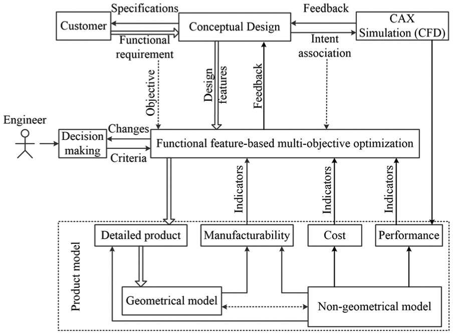
Product development routine.
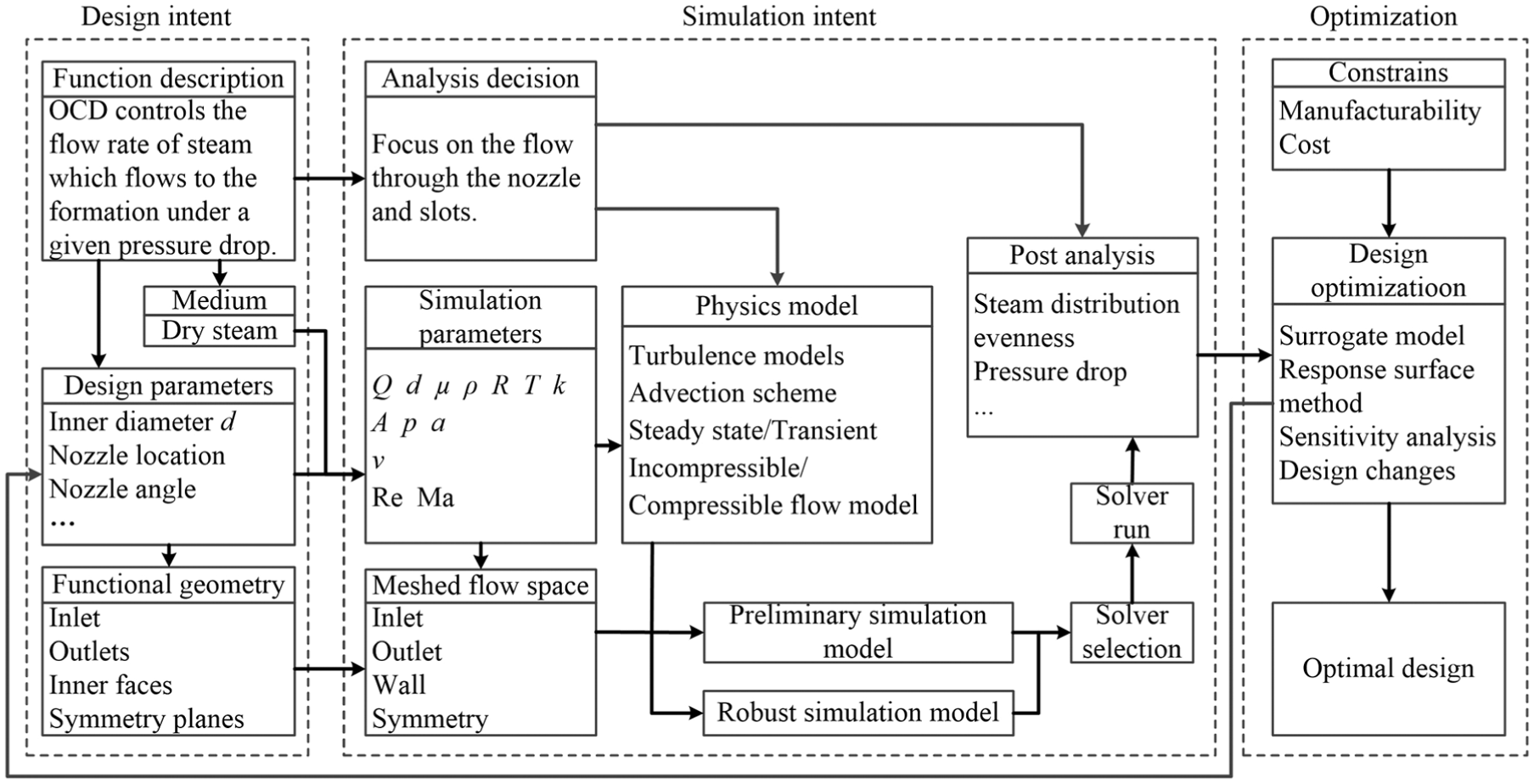
As to this article’s focus of CAD/CFD integration, in order to keep the consistency of design intent in different product development stages and to facilitate the correspondence of the design and simulation models, a CAD/CFD integration framework is proposed here, which is depicted in Figure 2.
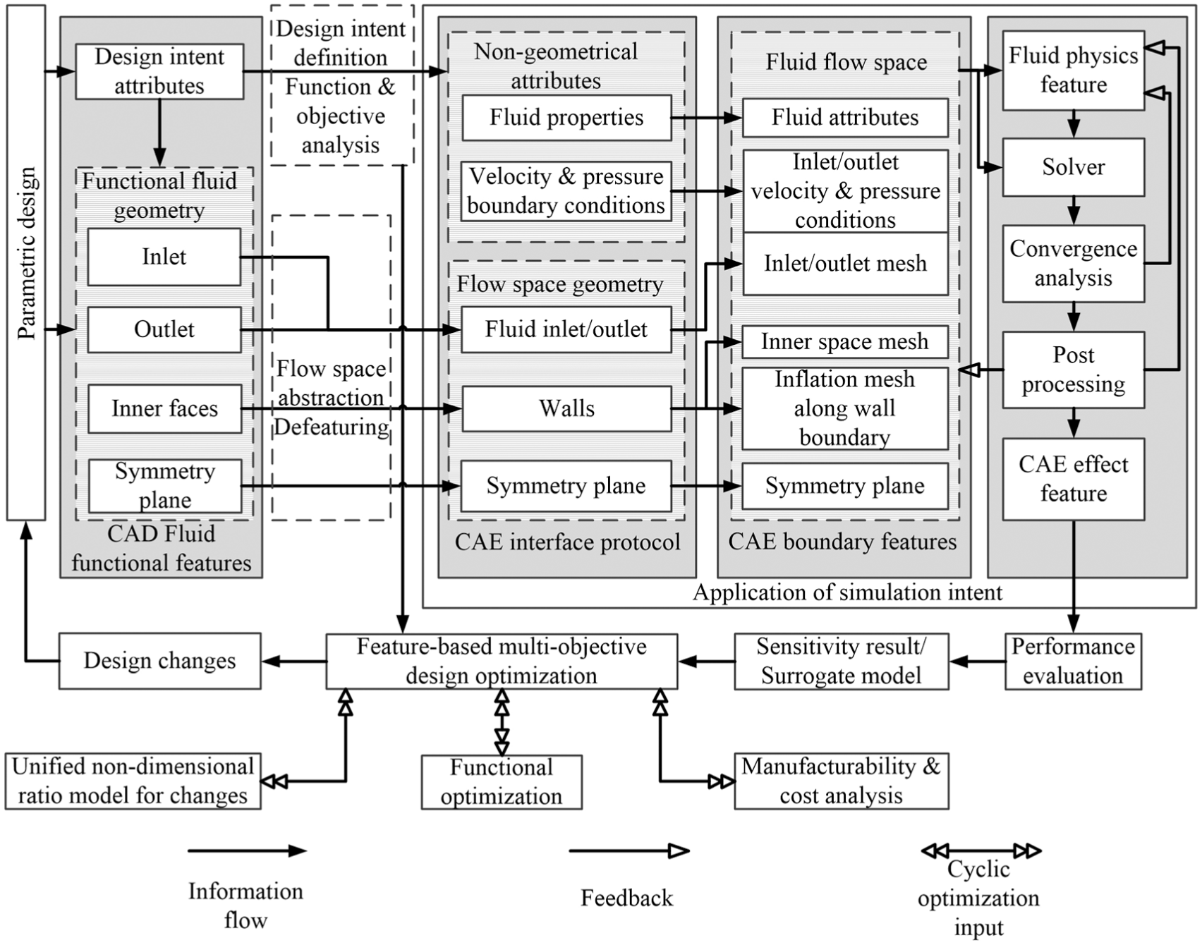
CAD/CFD integration framework.
As aforementioned, the design can be parameterized according to engineering knowledge. The parametric design enables a topology-based representation of the part, which maintains the design intent consistently. 17 Based on the functional requirements, fluid functional feature is defined as a class of design intent attributes which are composed of design parameters and functional descriptions, as well as functional geometry which is controlled by those attributes. 5 The functional fluid geometry can be itemized as inlet, outlet and inner faces enclosing fluid space and symmetry plane if there is any. In this way, the design intent can be fully conveyed by fluid functional features to the downstream analysis stage. The CAD model of the flow space can be extracted by Boolean operations. The face IDs of flow space geometry are assigned specific tags with attributions and boundary conditions attached, which will be recognized as a CAE boundary feature. A CAE boundary feature was defined as a class of features that contains the mapping relations of geometrical dependencies between CAD entities and their associated CAE mesh representations as well as non-geometrical dependencies, such as inherited properties, like fluid properties, fluid space body face names, tags, constitutional structures and conceptual constraints to apply CFD boundary conditions. 6 Consequently, the fluid flow space can be meshed with designated mesh types according to different boundary properties. For example, an inflation layer is applied along the wall boundary to capture the boundary layer accurately. Meanwhile, the boundary conditions are assigned accordingly. The fluid flow space including discrete geometry, boundary conditions and non-geometrical fluid attributes inherited from the design intent, is treated as the input of solving stage.
At the upper-right corner of Figure 2, fluid physics feature is defined as an object class with a characteristic set of fluid simulation setup parameters with a generic data structure and related methods. 5 Then, this fluid physics feature module also models a set of rules to select the appropriate CFD solver regime applicable to each round of simulation. This module is also designed to implement knowledge and best practices which enable the conversion of input data, assist CFD solver setup and generate a robust CFD model. Therefore, the simulation intent is embedded in the fluid physics feature instances. The detailed description of the fluid physics feature class will be illustrated in the next section. Post processing could be conducted based on any converged run. The CFD model including mesh and solver setup parameters could be updated iteratively, leading to a robust model setup. This is a unique requirement of CFD analysis which distinguishes it from linear engineering problems, such as stress analysis.
After achieving the robust CFD model, the initial design can be modified heuristically to approach design objectives. Then, based on the new design, the updated CFD analysis will be obtained accordingly under the aforementioned scheme. The CAE effect features are extracted from the difference between the incremental analysis results. 6 Following that, a sensitivity or surrogate model could be obtained to provide optimization input. Coupling with optimization objectives derived from design intent, operational performance, manufacturability and cost analysis, the optimization process takes different constraints into consideration, which eliminates the redundant communications between designer and other stake holders. Here, a unified non-dimensional ratio model is proposed to calculate the weights of different design criteria and to enable the measurement of performance increments between different designs. Finally, a closed CAD/CFD loop forms, which links the CAD domain and CFD domain consistently. Evidently, the design intent is adhered to throughout the whole process. The transfer of the design intent in this process is denoted by solid arrows which link the relevant blocks in Figure 2. At the same time, design intent and simulation intent are associated through the control of fluid functional features, CAE boundary features and fluid physics features.
Implementation of the proposed feature concepts
In this article, the fluid physics feature is established based on a compressible flow scenario, which is a challenging case in CFD application. The process of physical parameter analysis, CFD solver setup, convergence analysis and robust model generation is shown in Figure 3.
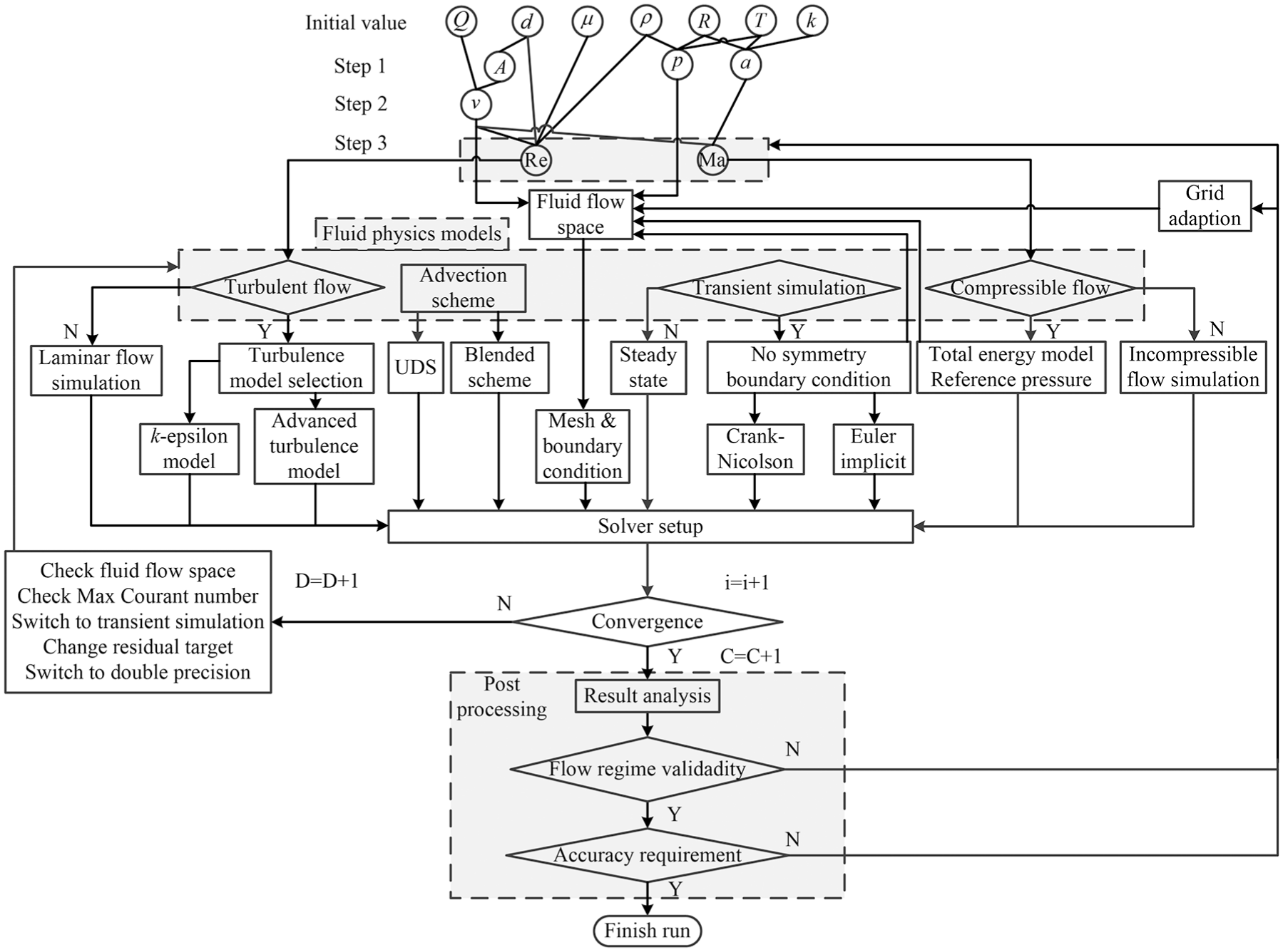
CFD simulation robust model generation cycles.
The initial values are the fluid attributes which are carried over by design intent to achieve specific product functional performance. The physical relationships between these parameters are applied as rules that have the form of equations listed below


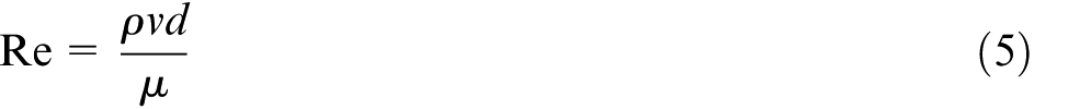

where A is the cross-sectional area of duct, d is the inner diameter of duct, p is the pressure of gas, ρ is the density of gas, R is the gas constant, T is the temperature of gas, a is the speed of sound of gas, k is the specific heat ratio of gas, v is the velocity of gas, Q is the flow rate of gas, Re is the Reynolds number, µ is the dynamic viscosity of gas and Ma is the Mach number.
Consecutively, the parameters in steps 1, 2 and 3 can be acquired through forward chaining. 9 It should be noted that the medium used in this case is ideal gas. If not, the knowledge base should be extended correspondingly. Providing the initial data pool is sufficient, the Reynolds number and Mach number in step 3 can always be obtained regardless of the occurrence sequence of the other parameters. Parameters like velocity and pressure are usually assigned to the boundaries as boundary conditions. As a consequence, they can be used to check the validity of the fluid flow space which will be the input of the CFD solver. The Reynolds number and Mach number are dimensionless quantities which determine the flow regime. Based on the Reynolds number, a turbulence model will be selected if the flow is turbulent. The Mach number judges the compressibility of the flow. A special model and setup are needed if the compressibility effects cannot be ignored. When the simulation is in the start-up stage or faced with convergence problems, lower order discretization schemes like upwind differencing scheme (UDS) and Euler implicit, as well as k-epsilon turbulence model if applicable, have the priority to be selected in order to assist convergence.
The index i will be updated after each simulation run. Indices C and D denoting the status of convergence will also be updated accordingly. The simulation solver setup is recorded no matter if the simulation is converged or not. If a simulation is converged, post processing will be conducted to check whether simulation results match the initial assumptions and expected accuracy. If not, grid adaption will be triggered based on the existing simulation result to examine where local mesh refinement is required. Simultaneously, the peak value of Reynolds number and Mach number will be checked to see whether the flow regime needs to be changed. If a simulation diverged, the system would try to alter the solver setup to achieve convergence. It is highlighted here that each time when a new iteration starts, only one change is made in the solver configuration to obtain the sensitivity toward different simulation schemes. If the simulation still has convergence problems after several successive runs, human intervention is needed to diagnose the problem, which requires more expert knowledge.
After rounds of successful simulations, the mesh is further refined, which is favorable for the application of higher order schemes and advanced turbulence model, if the flow is turbulent. Higher order schemes always have priority, when the iteration index is high. Thus, the final simulation quality can be guaranteed. The cycles stop when all the simulation requirements are satisfied. As mentioned earlier, the simulation setup is recorded dynamically in each iteration during this process. Li et al. 18 define the interim features between various manufacturing operations as dynamic features. Based on this concept, a novel operation planning method is developed for the machining of complex structural parts. 19 Applying the similar dynamic feature concept, in this work for CFD model generation, we define dynamic physics feature as the intermediate states of the fluid simulation model including flow properties, grid distribution and discretization scheme. 5 The dynamic physics feature is developed to facilitate the generation of robust simulation model. The robust simulation model is defined as the applicable CFD regime and simulation setup template with validated physics conditions, which converges into reasonable and accurate results. The understanding of flow physical behavior becomes more and more mature along with the development of dynamic physics features.
Optimization methodology
Optimization is carried out based on an integrated CAD/CFD feature model with associated geometry and parameters, robust simulation models, accurate results, effective optimization inputs and prospective manufacturability constraints. The semantic definitions and their relations among the involved features are shown in Figure 4.
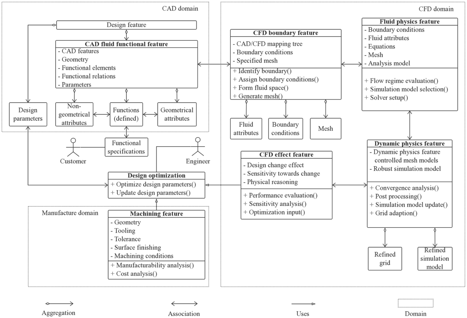
UML diagram representing inter-feature associations.
CAD/CFD integration eliminates many tedious intermediate procedures during the cyclic design loops, for example, repeated meshing and solver setup, which greatly improves the design efficiency. In addition, a critical factor to further enhance the efficiency is to automate the cyclic process by controlling the loops using optimization algorithms. Generally, the optimization can be performed based on gradient-based algorithms, stochastic algorithms and metamodeling-based algorithms. 20 Among them, the metamodeling technique shows advantages of high efficiency compared to stochastic algorithms and more general applicability, given problems where the gradient information is nontrivial to calculate. 21 Metamodeling approximates the empirical relationship between the objective function and the design variables, based on a group of experimental/numerical tests, where design of experiments (DOE) is widely adopted to reduce the number of tests. 22 This is very meaningful, especially when computationally expensive CFD simulations are involved. A general approximation-based optimization problem is formulated in the following equation
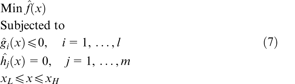
Some widely used metamodeling methods include the response surface method (RSM), the radial basis function (RBF)-based method and the kriging method, 22 where the RBF-based and kriging methods are more suitable to explore highly nonlinear design space, 21 and RSM fits better for engineering problems with a small group of design variables and a relatively regulated design space. 22 In this work, RSM is adopted and the response surface is approximated by quadratic polynomials. 23 To be specific, the quadratic response surface is mathematically described as follows
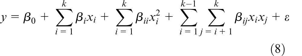
where y is the response function, x is the design variable, k is the number of variables, ε is the error and β is the regression coefficients.
Based on the experimental data, the coefficients in equation (8) can be obtained through regression analysis. Subsequently, the optimal combination of design parameters can be obtained by further optimizing the derived response function.
Case study
The OCD, applied in SAGD process, is studied in this section to show how the system works. In the oil industry, SAGD is applied as a practical method to extract heavy oil from tar sands. As shown in Figure 5, there are two horizontal wells in the SAGD completion. The injection well conveys steam to the formation where the steam cavern forms. The production well, which is drilled around 5 m below in parallel with the injection well, recovers the gravity-drained water and low-viscosity bitumen after heating cycles. The OCD regulates the flow rate of steam flowing to the formation under a given pressure drop. The slotted liner covering the OCD is used to protect the device against the sand surrounding the well. When steam flows into the device, a portion of it flows to the outer space through the nozzles radially located on the device. The majority of steam continues flowing to the downstream. By adding steam injection points between the heel and toe of the injection well, the OCD contributes to creating an even distribution, which alleviates the barbell-shaped steam chamber induced by the traditional two-injection tubing design. 24 Furthermore, the use of OCDs enables the conformance of the steam injection profile with the reservoir “pay thickness” (height of oil sands layer) along the well, which promotes steam chamber growth and reduces steam–oil ratio (SOR). 25
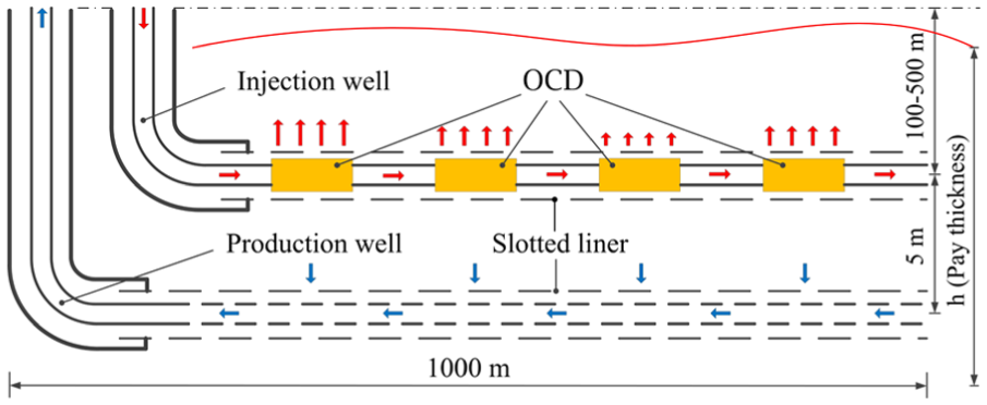
SAGD well completion. 26
The performance of the OCDs is significant to the SAGD process efficiency. Some research has been done to optimize the number and locations of OCDs.27–29 However, the design optimization of a single OCD device through a physically realistic CFD simulation is still needed. Figure 6 shows the overall data flow in the OCD optimization based on the proposed CAD/CFD integration system. This process will be illustrated in detail in this section.
Association of design and simulation intent in OCD optimization.
In this case, water ideal gas (steam) at the temperature of 500 K is assumed to be pumped into the injection well at a flow rate of 0.24 m3/s. Figure 7(a) shows that the functional fluid geometry is itemized as inlet, outlets, inner faces and symmetry planes. In this way, the fluid functional feature is fully defined, which conveys the design intent to the next stage in the integration loop.
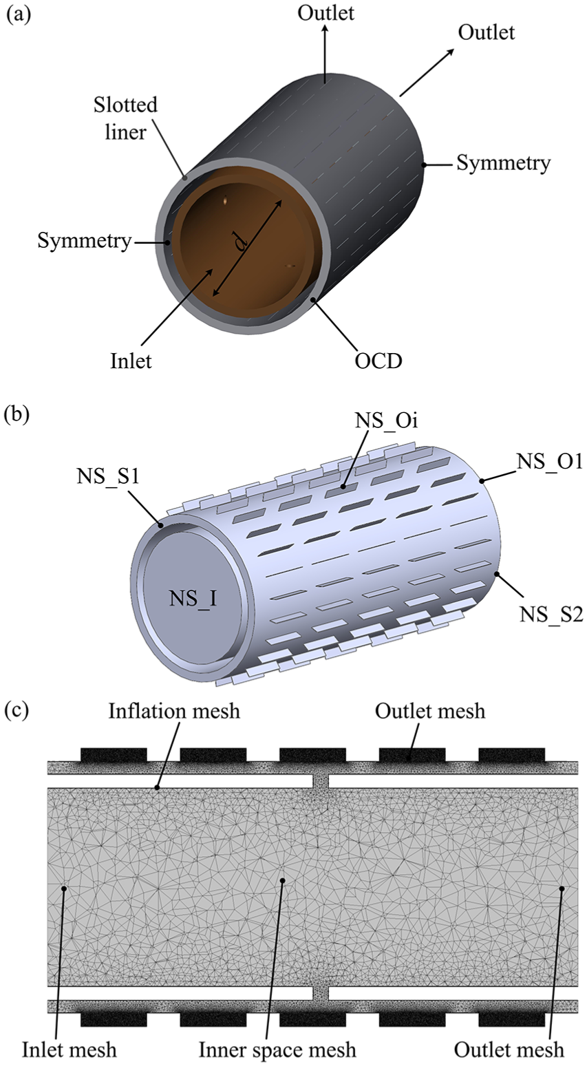
Model conversion in CAD and CFD: (a) OCD and slotted liner CAD model, (b) fluid domain and (c) initial mesh generation.
In order to reduce the process time, the fluid domain can be established using SolidWorks parametrically, as shown in Figure 7(b). Beneficially, the flow space can be easily updated subject to design changes. Tags with attributes, similar to named selections, are assigned to the fluid geometrical faces to transmit boundary information in CAD/CFD conversion. Using the CAD Configuration Manager provided by ANSYS Workbench, the simulation platform can visit and modify the geometry file constructed by SolidWorks. The attributes attached by tags are used to guide the mesh generation as shown in Figure 7(c). Consequently, CAE boundary features are established, resulting in the generation of the fluid flow space, which is the input of the fluid physics feature module.
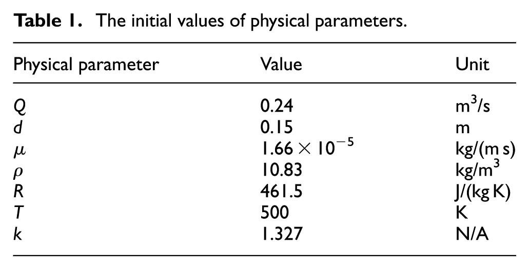
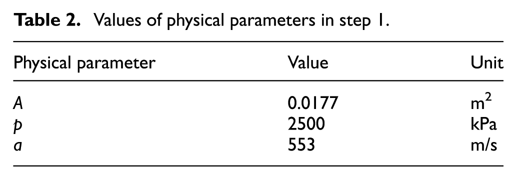
The initial values of the physical parameters are given in Table 1. Table 2 shows the parameters calculated in step 1. The pressure derived in this step is assigned as the pressure inside the tool which is treated as the reference pressure. According to the OCD working conditions, 30 the outlet boundary condition is allocated to NS_Oi and NS_O1 in Figure 7(b) as −50 and 0 kPa, respectively. Here, i is the number of the slots. The inlet velocity is found to be 13.5 m/s in step 2, and it is assigned to NS_I as the inlet boundary condition. In step 3, the Reynolds number is calculated to be 1.32 × 10⁶, which is much bigger than the turbulence transition Reynolds number in a pipe. The Mach number is 0.02, which is much less than 0.3. So, the flow is assumed to be incompressible turbulent flow. The k-epsilon turbulence model and the UDS advection scheme are selected at this initial stage to facilitate convergence. The simulation type is steady state. The fluid physics models selected in this simulation are shown in Table 3. Using ANSYS CFX as the solver, the simulation converges and the Mach number contour obtained from this initial run is shown in Figure 8.
The initial values of physical parameters.
Values of physical parameters in step 1.
Fluid physics models of the initial run.
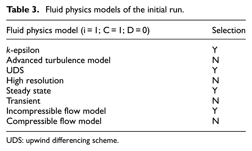
UDS: upwind differencing scheme.
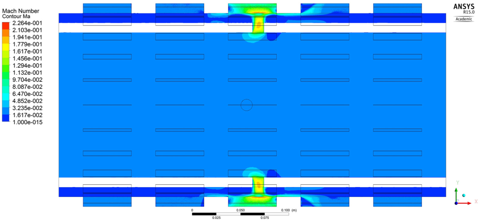
Mach number contour of the initial run.
Although the initial run converged, it is found that the maximum Mach number is close to 0.3, which means that compressibility effects cannot be ignored. Based on the simulation result, grid adaption is conducted, which is shown in Figure 9. The total energy model is selected to activate the compressible flow simulation. The other solver setup parameters remain unchanged in the next run.
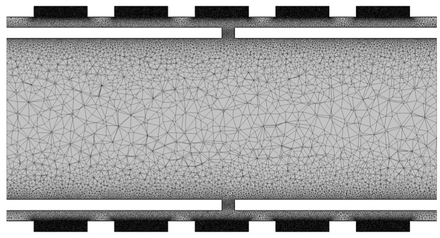
Grid adaption.
After a few iterations, the dynamic physics feature is developed to enable the acquisition of sensitivity toward different physical models. Consequently, a robust simulation model is obtained. The physics models selected for this robust simulation model are shown in Table 4. The velocity vectors derived from this final run are shown in Figure 10.
Fluid physics models of the final run.
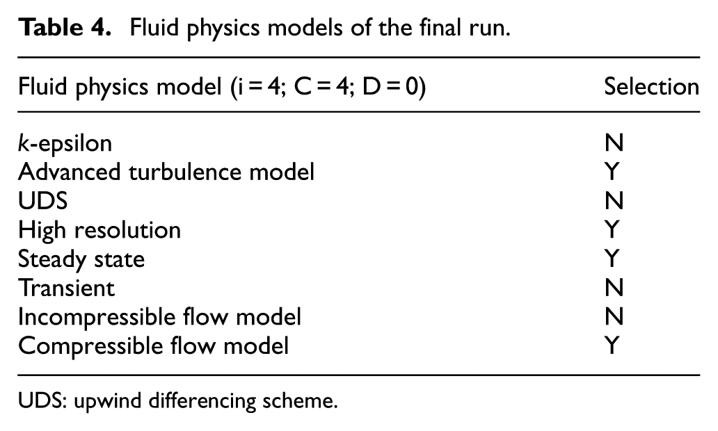
UDS: upwind differencing scheme.
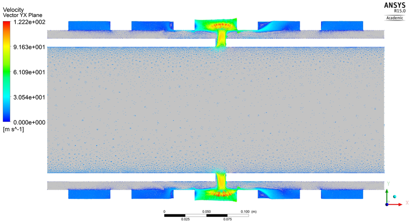
Velocity vectors of the final run.
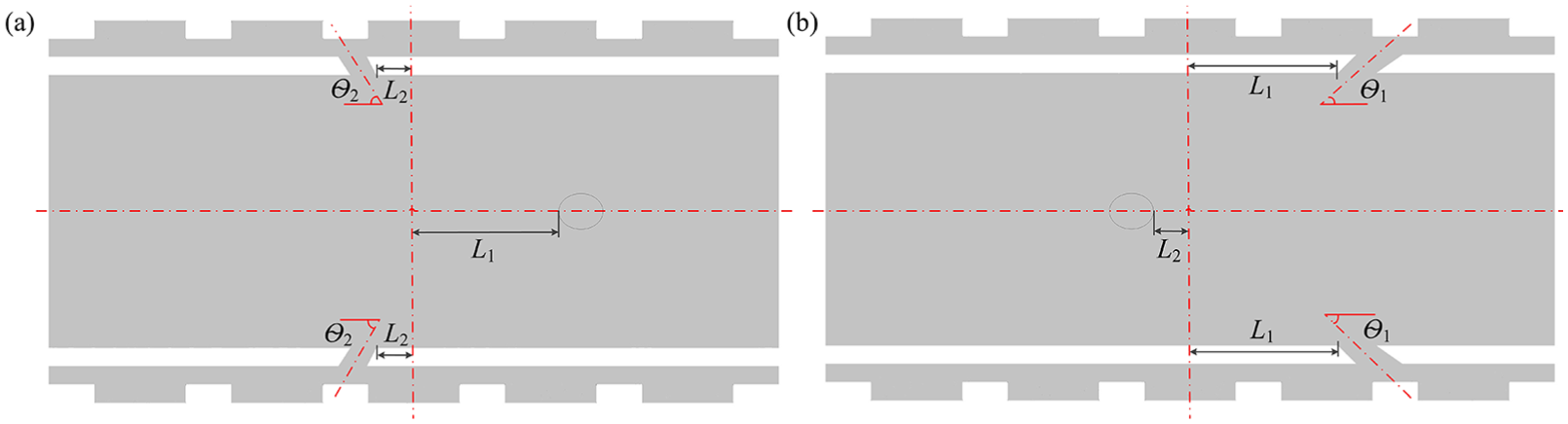
The steam going through the slots is expected to evenly distribute, in order to form the steam cavern more precisely in the SAGD completion. To quantify the steam distribution, the function Es is defined by calculating the deviation of mass flow rate through a specific slot from the even distribution situation, which has the specific expression as
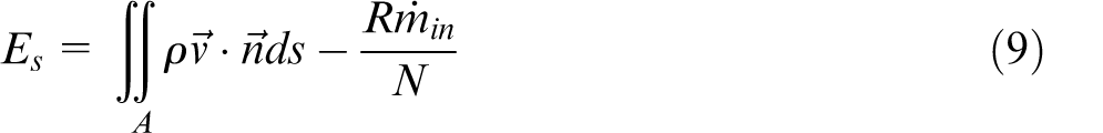
where ρ is the density of steam,
Correspondingly, Eo is defined as the variance of the mass flow rate through slots
Ideally, Eo is 0, that is, the steam flow through the slots complies with the even steam distribution scenario. Hence, a smaller Eo means better overall evenness, which is treated as the optimization objective derived from the design intent. Eo is calculated in CFX-Post as an expression and it turned out to be 2.89 × 10⁻⁶ kg2/s2 in the final run. Eo can be normalized by dividing by the average mass flow rate through the slots.
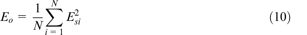
In order to optimize the OCD performance, five design variables are selected to investigate their effect on the steam evenness factor while the other design parameters remain fixed. Four of the variables are shown in Figure 11, where L1 and θ1 control the two nozzles pointing in the same direction with the flow inside the pipe while L2 and θ2 control the two nozzles pointing in the opposite direction. The fifth parameter is the conical angle γ which controls all the four nozzles.
Design variables: (a) horizontal plane cross-section view and (b) vertical plane cross-section view.
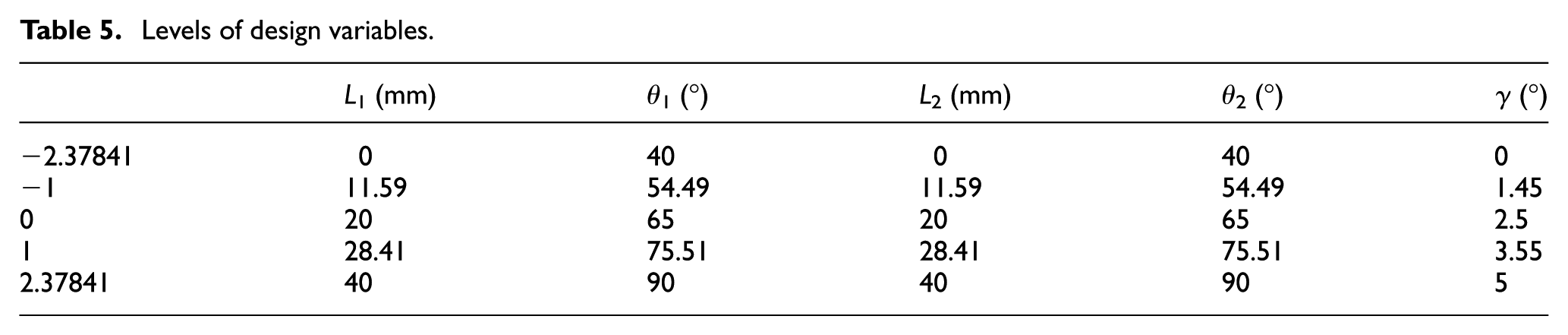
Central composite design (CCD) 31 is applied to design the experiments, which forms 44 sets of experiments subjected to the five design variables with five levels each. The values of the design variables are coded as shown in Table 5.
Levels of design variables.
Under the integrated environment, the fluid geometry can be easily updated to conduct the 44 sets of numerical experiments. The simulated objective values are recorded accordingly. For each design point, the robust simulation model is used to conduct the simulation and ensure the results are trustable. Meanwhile, it should be noted that every time an updated fluid domain occurs, the validity of the robust simulation model is checked according to the method described in section “Implementation of the proposed feature concepts.” If the simulation model failed in a new design, another robust simulation model will be generated for this design point specifically. As a result, the accuracy of each design point can be guaranteed, which provides effective inputs for the optimization process.
Finally, the log file recording the simulation results is post-processed in MATLAB. Judging the result obtained, we found that the error between the derived minimal point’s normalized evenness factor and the value from simulation validation is not acceptable. This is due to insufficient data input while the OCD flow is complex.
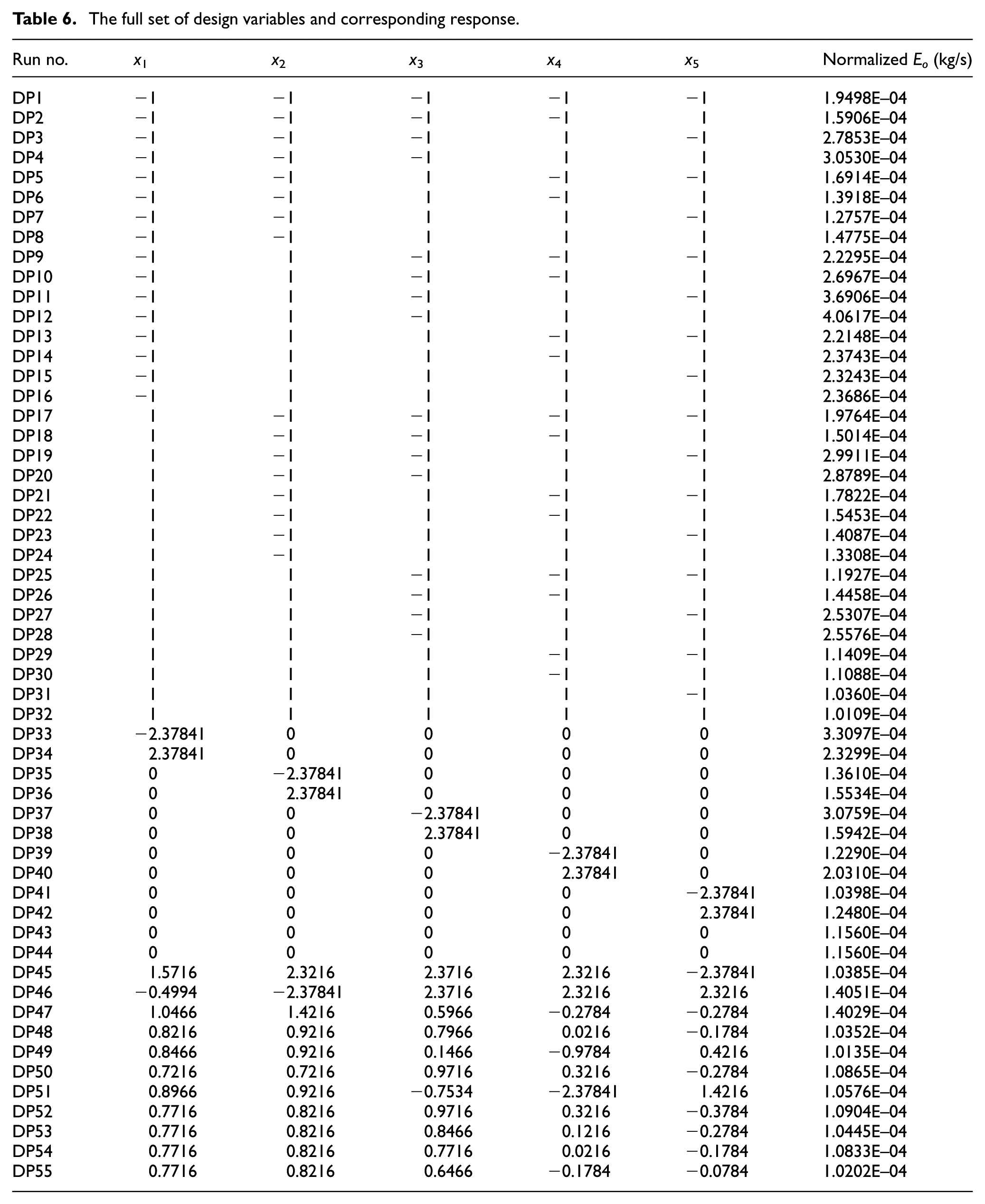
In order to obtain accurate optimization results, more design points are added adaptively based on the initial metamodel. 32 To achieve this, the evenness factor of the derived optimal point through RSM is calculated through simulation and treated as the new input for the next round of approximation. Finally, the full data collected is shown in Table 6. By regression analysis, the response function can be obtained as
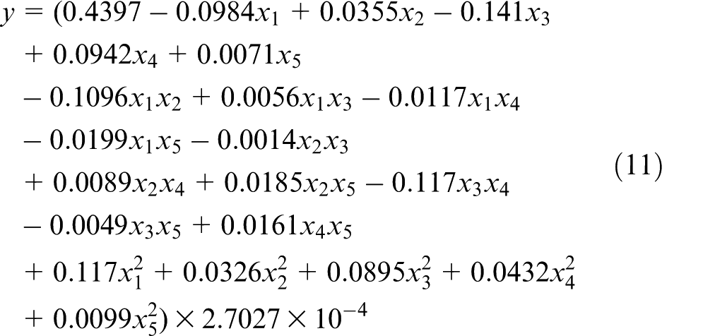
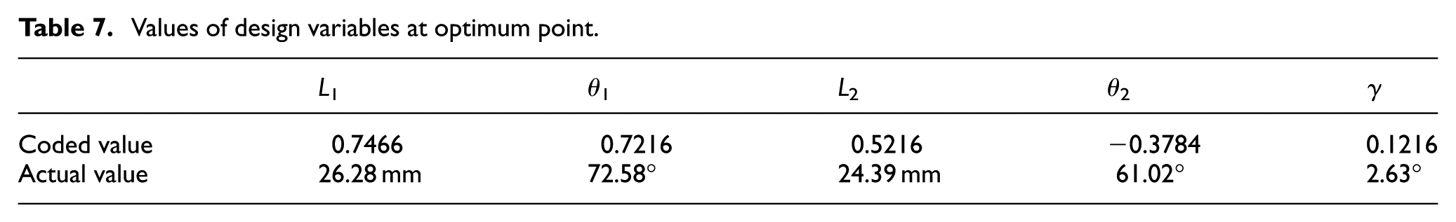
where y is the normalized evenness factor while x1, x2, x3, x4 and x5 are variables which represent the coded value of L1, θ1, L2, θ2 and γ, respectively. The average approximation error of this function is 6.7%. Using this function, the minimal normalized evenness factor is found to be 0.9776 × 10⁻⁴ at the design point shown in Table 7. This design point is validated by simulation, and the simulation result of the normalized evenness factor is 1.0032 × 10⁻⁴, which leads to a relative error of 2.6%.
The full set of design variables and corresponding response.
Values of design variables at optimum point.
The influence of design variables is analyzed, as shown in Figure 12. The green line shows the contour of the response surface against a single variable while all the other variables remain fixed at the point shown in the figure. The two red curves indicate a 95% simultaneous confidence band for the fitted response surface. Obviously, the evenness factor is highly affected by the first and third variables, namely, the nozzles’ distances to the central plane. The effect of the slant and conical angles is quite small. The streamlines flowing through the four nozzles are generated to show how the flow develops in the optimized OCD, as demonstrated in Figure 13.
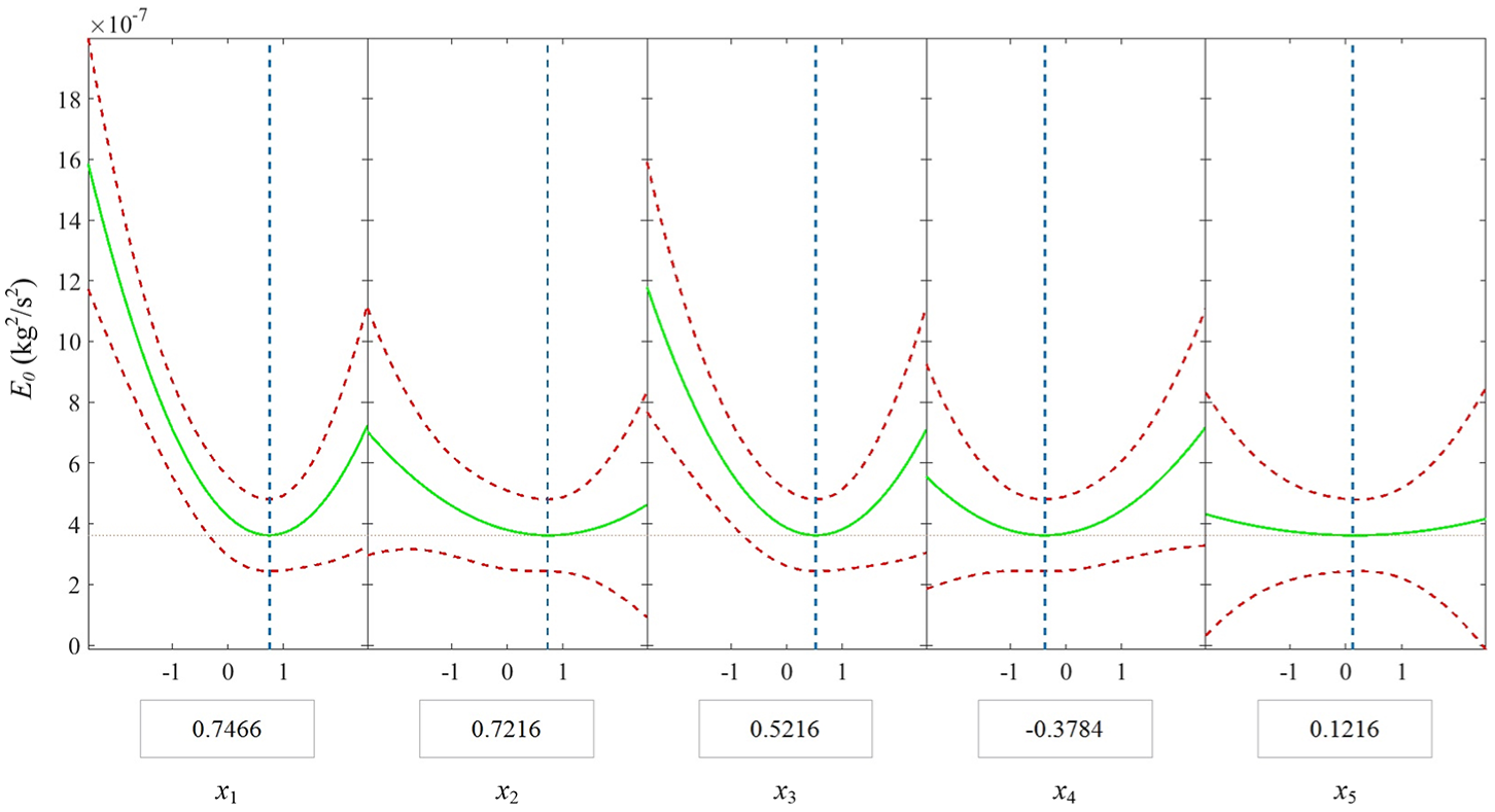
Influence of design variables.
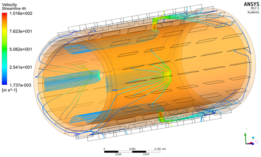
Streamlines through the four nozzles of the optimized design.
Conclusion
This article contributes to a feature modeling and integration method for CAD and CFD to address the solver usability problem faced by many CFD users. The complex CFD solver setup process has been intelligently coupled with feature-based parametric design optimization, which otherwise would be highly knowledge-demanding and would also encumber the cyclic integrated optimization of design via interactions between CAD and CFD. Fluid physics features and dynamic physics features, which convey the simulation intent, have been used to assist input data processing, solver setup, convergence analysis and robust simulation model generation. In this way, semi-automation of CAD/CFD integration has been achieved. Through the collaboration of fluid functional features, CAE boundary features, fluid physics features and dynamic physics features, design intent and simulation intent are associated seamlessly, leading to the consistent transmission of design intent throughout the whole integrated CAD/CFD system.
The effectiveness of the integration system is demonstrated through the case study of OCD applied in SAGD. It should be highlighted that the robust simulation model is constructed progressively under the scheme we put forward. Relying on the robust simulation model, design optimization is conducted to achieve better steam distribution. In this process, the intelligent functions are implemented through physical knowledge and best practices in CFD. By adapting the physical knowledge, this method can be applied to other practical engineering problems. As to typical CAD/CFD integration problems in application fields, the authors would assure that the reported SolidWorks/ANSYS models can be directly applied without major technical barriers. Therefore, this article provides a generic approach to aid decision making in CFD simulation setup and thus facilitate the design optimization.
In the future, the automated function in the CFD model generation process needs to be fulfilled based on the novel feature concepts we proposed. The optimization of OCD can be further conducted, incorporating cost functions and manufacturability constraints.
Footnotes
Acknowledgements
The authors acknowledge Natural Sciences and Engineering Research Council of Canada (NSERC), RGL Reservoir Management, China Scholarship Council (CSC), University of Alberta and Alberta Innovates Technology Futures (AITF). Special thanks to Dr Tsai in University of Alberta for her help with the high-performance computing. The authors declare that RGL is the manufacturer of outflow control devices (OCDs); the example case was generated by the authors for academic interest.
Declaration of conflicting interests
The author(s) declared no potential conflicts of interest with respect to the research, authorship and/or publication of this article.
Funding
The author(s) disclosed receipt of the following financial support for the research, authorship, and/or publication of this article: This research received NSERC Discovery Grant for Y.M., NSERC CRD Grant for C.F.L. and financial support from RGL Reservoir Management’s contracts with Y.M. and C.F.L. L.L. also received stipend funding from CSC, University of Alberta and AITF.