
Abstract
The implementation of structural health monitoring (SHM) systems in existing civil engineering structures could contribute to a safer and more resilient infrastructure as well as important savings. Due to their light weight, small size, and high resistance to the environment, distributed optical fibre sensors (DOFS) stand out as a very promising technology for damage detection and quantification in reinforced concrete (RC) structures. In this paper, the performance of DOFS featuring an external polymeric cladding with rough surface, to accurately assess deflection and crack width of a stainless-steel RC beam subjected to four-point bending is investigated. Several sensor positions, both embedded in the concrete and attached to the surface, are investigated in a multi-layer configuration. The study revealed that embedded sensors yield very accurate results regardless of the sensor position and the load level, that is, service or ultimate loads, being the sensor glued in a premade groove on the steel bar the most reliable solution for high-load levels. Conversely, externally deployed sensors for the assessment of existing structures, described attenuated values for the measured deflections, and, to some extent also the crack width, due to a loss of bond between the sensor and the surrounding concrete, already for service loads. Corrective methods to further use the obtained data are presented, yet the clad DOFS attached to the concrete surface described a significant drop of performance with increasing load levels, showing an important loss of data at 80% of the ultimate load.
Keywords
Introduction
Deterioration of reinforced concrete (RC) structures due to ageing or premature deterioration puts the safety of the users at risk and has a huge impact on the competitiveness and welfare of a country at a global scale, yet the economic impact of replacing existing deteriorated structures would simply be too high. Consequently, methods and techniques allowing for increasing service life, even beyond the one the structure has been designed for, are paramount. Therefore, the implementation of effective damage identification and assessment strategies that allow for a proper evaluation of ongoing deterioration processes is key to enable maintenance/repair/strengthening directed strategies from infrastructure owners aiming at the preservation of the existing infrastructure stock.
In this context, the implementation of a Structural Health Monitoring (SHM) system is stated as a key factor to attain such goal. Indeed, the detailed monitoring of a structure’s performance over its service life would enable the early detection of structural faults, which could prevent the occurrence of potentially catastrophic events while providing valuable information for the optimization of future structural designs. Moreover, with a continuous reliable monitoring system in place, the current time-based inspection model could be replaced by a performance-based or risk-based inspection approach. Furthermore, today’s maintenance paradigm could shift from corrective to preventive, thus resulting in tremendous savings in infrastructure maintenance and a reduction of its associated social impact. However, to date, the use SHM is not yet a generalized practice in civil engineering due to the lack of reliable, scalable and affordable monitoring solutions. 1
Subsequently, the development of SHM systems for damage detection based on optical fibre sensors has risen as a very promising alternative in the last decades. Optical fibre sensors present several advantages compared to traditional sensors, them being small in size, light weight, chemical and corrosion resistant and immune to electromagnetic fields. 2 In this context, Fibre Bragg Grating and Fabry-Perot have been widely researched and to date are the most used type of optical fibre measurements in practice. 3 However, these two types of sensors have clear limitations with respect to the maximum number of measuring points along an optical fibre and their spacing, thus being often referred to as quasi-distributed sensors, making them less suitable for specific applications such as crack detection in concrete structures, thereby failing to provide an accurate description of the structure’s condition.
More recently, Distributed Optical Fibre Sensors (DOFS) featuring unprecedented spatial resolutions have been developed, thereby opening for new possibilities in the development of damage detection systems. The working principle of DOFS is based on the analysis of light backscattering that occurs along the fibre due to three different processes: Raman, Brillouin and Rayleigh scattering. Raman scattering is highly sensitive to temperature variations, consequently its application has been mostly limited to fields other than civil engineering. 4 Brillouin and Rayleigh scattering, on the other hand, are both sensitive to temperature and strain variations, yet they present fundamental differences with respect to spatial resolution and measuring range. Indeed, DOFS based on Brillouin Optical Time Domain Reflectometry (BOTDR) feature a spatial resolution in the order of the tens of centimetres 5 but their measuring range can reach lengths of up to 300 km. 6 Conversely, the sensing range of Rayleigh-based DOFS is currently limited to 100 m, but they boast an unmatched spatial resolution in the sub-millimetric scale. 7
Owing to such capabilities, a significant amount of research has been conducted to investigate the applicability of DOFS for the monitoring of RC structures. As result of those investigations, the suitability of DOFS for the evaluation of key performance indicators has been demonstrated experimentally for Brillouin-based DOFS8–11 and Rayleigh-based DOFS.12–16 Significant efforts have been carried out for the assessment of crack widths using Rayleigh-based DOFS using different approaches. On one hand, strain transfer models that account for the differential strain between the fibre sensor core and the substrate due to the deformation of intermediate layers (cladding, coating, buffer and adhesive) have been developed to establish a direct correlation between the opening width of a crack and the strain measured by the optical fibre sensor. Examples of such models and its application can be found in refs. 17–19. However, the proposed models require the calibration of the shear lag factor, a parameter that depends on the material and geometrical properties of the cables, while such models are not directly applicable to fibre sensors bonded to the reinforcement, where the assumption of perfect bond between the sensor and the cracked substrate (concrete) is not fulfilled due to slip of the reinforcement. On the other hand, several studies have aimed at estimating the crack width based directly on the shape of the strain measurements performed. Rodriguez et al.20–21 presented a methodology to estimate the crack width of bending and shear cracks from strain measurements of DOFS bonded to the surface of the concrete. Similarly, Poldon et al. 22 used nylon-coated DOFS installed on longitudinal reinforcement bars to calculate crack slips and widths as well as to assess the vertical deflections of RC beams through double integration of curvatures obtained from the strain at different heights. Brault and Hoult 23 had previously shown that multiple cracks as well as deflections could be also accurately measured using DOFS longitudinally bonded to the surface of RC beams. Further experimental work by Berrocal and Fernandez24–26 revealed that by using strain measurements from robust DOFS, a good estimation of the crack width of multiple individual bending cracks and deflections in RC beams can be achieved, without the inclusion of strain transfer models between the fibre core and the substrate element, both for short and long-term monitoring.
Despite of the very promising results, two aspects remain to be further investigated; the type of optical fibre sensor commonly used in a large part of the available research is a thin polyimide-coated low-bend loss fibre featuring a diameter of between 125 and 155 µm, which present several limitations, both practical and technical.27–30 Consequently, later studies driven by the need of more robust solutions have investigated benefits and drawbacks of DOFS featuring one or more protective layers (cladding, coatings, buffers, etc.) around the glass core,19,31,32 yet the study of new clad/robust sensors is needed to validate its use in monitoring of RC structures. Additionally, while most of the research has shown very promising and interesting results on the application of DOFS for SHM systems, most of this research is on newly built structures, that is, embedded sensor solutions; therefore, applications on existing structures, that is, where the sensor is deployed attached to the surface of a hardened concrete element, are very scare, focused on on-site applications33–38 and limited to service loads.
This paper reports the results of an investigation of the suitability and performance of clad optic fibre cables to assess cracking and deflections of stainless-steel RC beams under service and ultimate loads. In particular, the work focuses on the analysis of Rayleigh scattering based DOFS measurements without the use of strain transfer models between the fibre core and the substrate element. Therefore, laboratory experiments were carried out to assess the performance of clad fibre optic cables deployed at different positions of the concrete section, both embedded in the concrete and externally glued to the surface. The results were compared against other techniques such as Digital Image Correlation (DIC), to evaluate its performance and reliability. Furthermore, this study investigates the suitability of the use of clad DOFS in existing structures for service loads and its limitations under ultimate loads.
Experimental programme
An experimental programme was devised to investigate the performance of clad DOFS to provide accurate information about a structure’s serviceability condition and ultimate limit state under cyclic loading, for both new and existing structures. The programme also studied different deployment positions for the sensor. Therefore, a RC beam, outfitted with DOFS deployed in a multi-layer configuration, was cast and cyclically loaded in two stages: (a) an initial set of cycles under service loads; and (b) a subsequent set of cycles of increasing load up to failure. The most relevant aspects of the experimental programme are described in the following.
Geometry and reinforcement layout
The specimen used in this work was a RC beam with a total length of 3 m and a rectangular cross-section of 200 × 250 mm. The beam was reinforced with three ∅16 mm rebar at the bottom and two ∅10 mm at the top. Moreover, six ∅8 mm closed-loop stirrups equally spaced at 200 mm were placed on either side of the beams. All reinforcement was made of duplex stainless-steel reinforcement type EN1.4362 with nominal yield strength of 700 MPa. Plastic spacers were placed between the stirrups and the bottom and lateral sides of the form to ensure a clear concrete cover of 20 mm. The ends of the bottom bars were bent upwards to improve the anchorage. The geometry and reinforcement layout of the beam is presented in Figure 1(a) and (b). (a) Geometry of the beam specimen, reinforcement layout and DOFS configuration (all measurements in mm) and description of the sensor name coding (b) test setup configuration.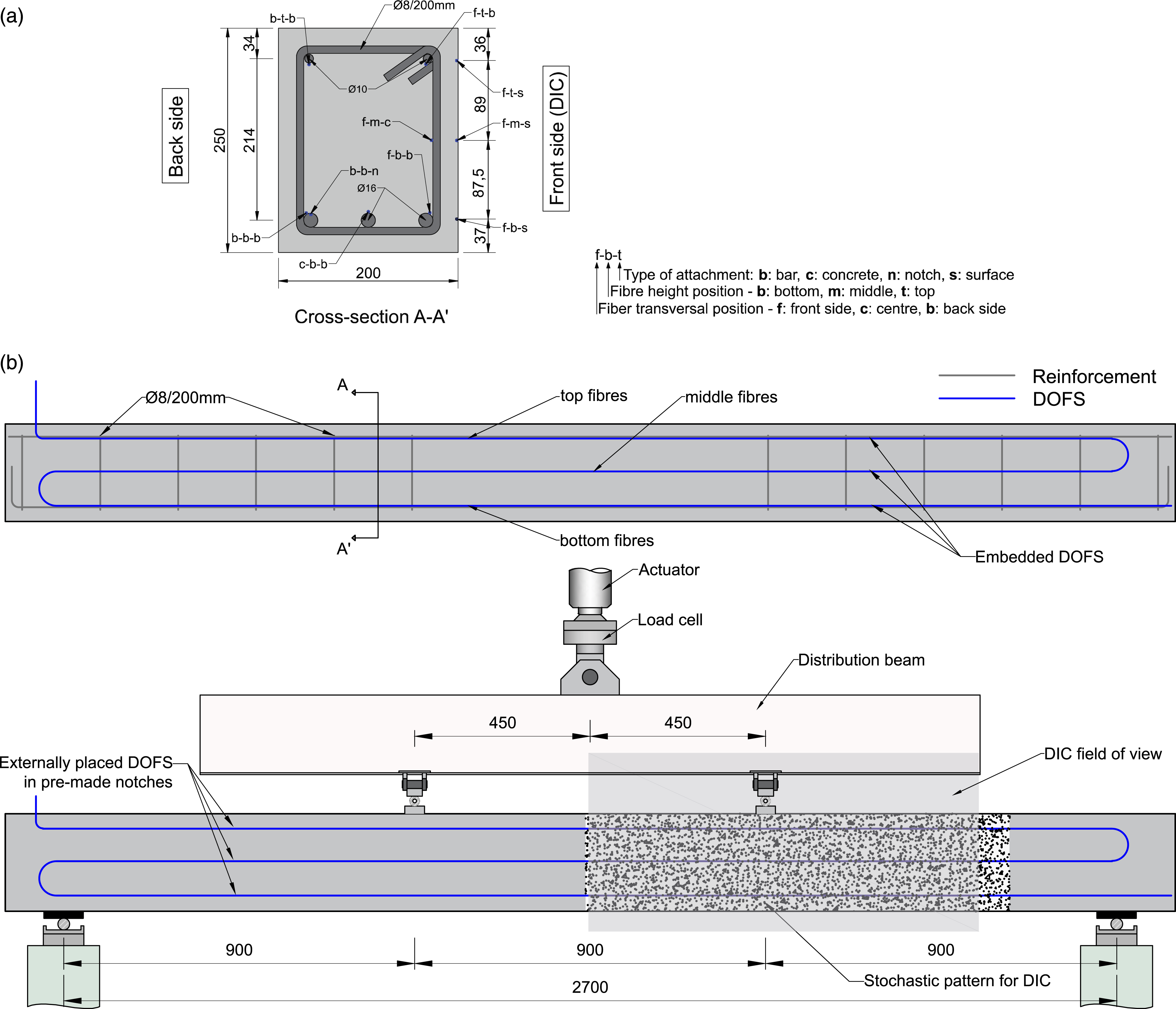
A self-compacting concrete mix with a water-to-cement ratio (w/c) of 0.45 was used to cast the beams. The mix included a sulphate resistant Portland cement with low C3A content and moderate heat development. Following the casting, the beam was covered with a polyethylene sheet to reduce moisture evaporation and stored in an indoor climate (20 ± 2°C and 60 ± 10% RH) for a month until it was tested. The concrete compressive strength at 28 days was 65.1 MPa (CoV = 5.2%) based on tests performed in accordance with EN 12390-3:2009 39 on three 150 mm cubes.
Instrumentation
In this study, the clad fibre optic cable BRUsens V1 from Solifos, featuring an external polymeric cladding with rough surface, was used. The V1 cable has a 2.8 mm diameter and its minimum bending radius, when tensioned, is about 56 mm, which makes it stiffer and more suitable for surface applications than other cables without a protective cladding, such as the 125 µm-thick polyimide-coated fibres commonly used in several research studies, see, for example, Refs. 21, 40 and 41. Conversely, the V1 cable can be easily handled and deployed without risk of rupture, making it especially suitable for embedding in concrete and post-casting applications. Furthermore, a recent study by the authors showed that clad/robust cables are less sensitive to local disturbances, thus less prone to yield strain reading anomalies. 24
A single 50 m long clad DOFS was installed in a multi-layer configuration to monitor the variation of strain along the beam in the region between the supports at 8 different locations of the beam’s cross-section: inside the concrete above the two outer tensile rebars (f-b-b and b-b-b); inside the reinforcement bar inserting it into a previously milled groove (b-b-n); inside the concrete under the compressive rebars (f-t-b and b-t-b); inside the concrete at mid-height of the cross-section (f-m-c); and the last three were externally inserted on pre-made notches on the concrete surface, at the top, mid and bottom levels of the section height (f-t-s, f-m-s and f-b-s), see Figure 1(a) and Figure 2(a) to (d) for clarity. The DOFS were either supported along the longitudinal reinforcement (f-b-b, b-b-b, f-t-b and b-t-b), fixed to the stirrups (f-m-c) or glued with a two-component epoxy resin (b-b-n, f-t-s, f-m-s and f-b-s). Installation of the optical fibre sensors: (a) installation of clad DOFS cable in a reinforcement bar by inserting it into a previously milled groove; (b–c) installation of clad DOFS on the surface of a reinforcement bar by mechanically anchoring the cable to the reinforcement with electric tape; (d) installation of clad DOFS attached to the concrete surface inserted in previously milled grooves.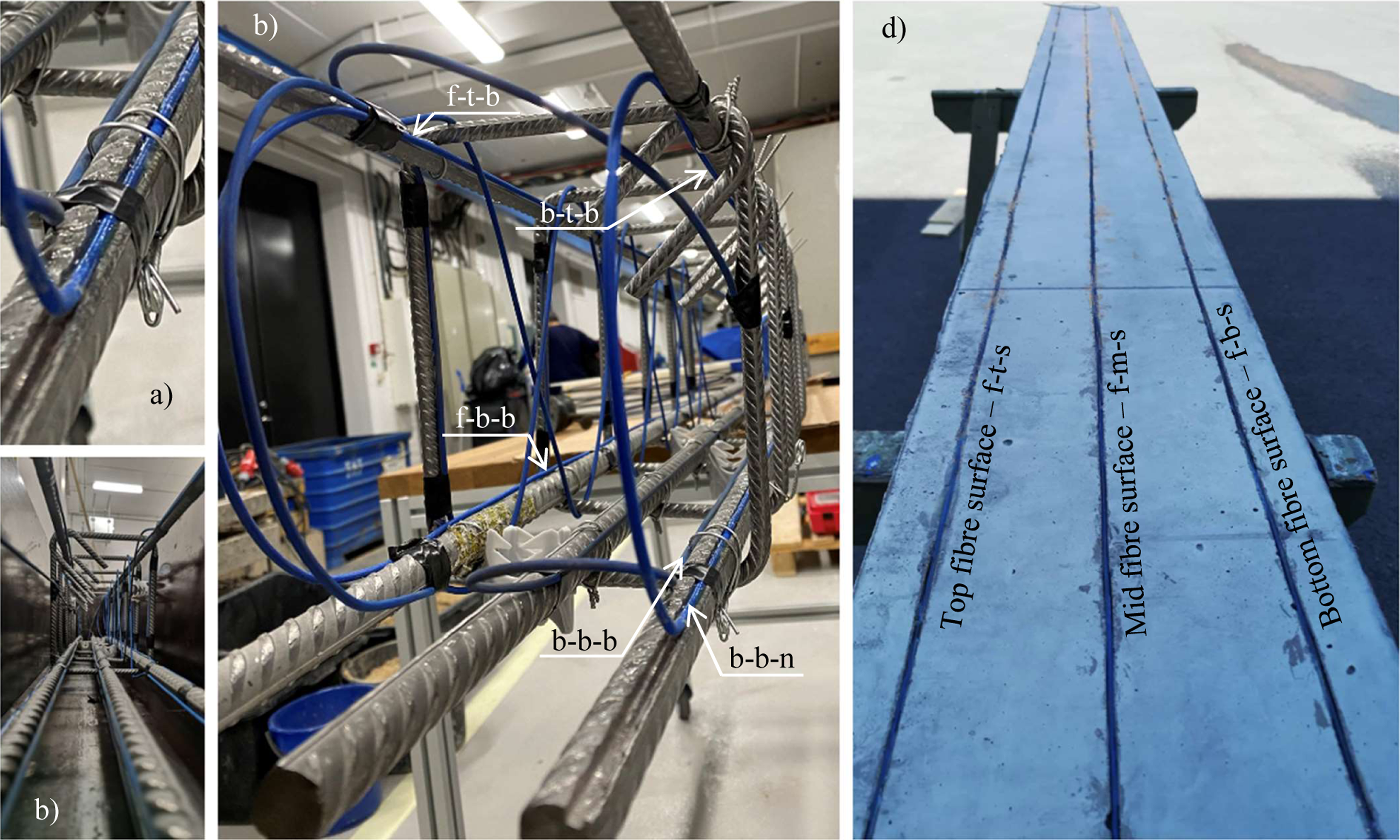
The Optical Distributed Sensor Interrogator (ODiSI) 6000 series from Luna Inc. was used as data acquisition unit. This instrument offers a strain resolution of 1 µε, a maximum strain range of ± 15000 µε and a sample rate that can go up to 250 Hz depending on the gauge pitch, cable and length and number of active channels. In all tests, the largest available spatial resolution between measuring points provided by the interrogator was chosen, namely, 2.6 mm. This configuration provided a combined accuracy (sensor + interrogator) of ± 15 µε, whereas the sample rate was set at 1 Hz. It is worth noting a cubic Hermite polynomial interpolation with a spatial resolution of 10 mm was performed on the measured raw data before proceeding to the analysis of the results in order to reduce the data volume without compromising the accuracy.
Digital Image Correlation was also used on one of the lateral sides of the beams to measure the full-field deformation and surface strains. For that purpose, the commercially available system from GOM, ARAMIS®, consisting of an adjustable stereo-camera setup was employed with a sampling rate of one picture per second. The DIC system provided a maximum measurement volume of 980 × 795 × 795 mm3 which enabled the monitoring of the half central part of the beam comprised between the two loading points and half of the shear span comprised between a point load and the support, see Figure 1(b). The results of the DIC were used as reference to assess the accuracy of the DOFS in determining the position and width of the cracks as well as the beam’s deflection.
Test setup and loading procedure
The beam was simply supported on rollers and loaded under four-point bending. The clear span between the centre of the supports was equal to 2700 mm. The load was introduced using a single actuator acting on the middle of a steel distribution beam equipped with two movable bearing supports symmetrically placed at 900 mm from the rollers, thus dividing the beam in three equal spans of 900 mm, see Figure 1(b). Loading was applied under displacement control using a closed-loop feedback system at a displacement rate of 3 mm/min. Several load cycles were performed reaching a maximum total load of 80 kN for the cyclic test (serviceability load levels up to 60% of the ultimate load) and unloading down to 5 kN total load. The test to failure was conducted similarly, that is, applying cycles, up to the failure of the beam was reached. The loading setup is schematically illustrated in Figure 1(b) and the loading scheme in Figure 3(a) and (b), for the SLS and ULS loading respectively. Loading setup and load versus time for both: (a) cyclic test (SLS) and (b) loading to failure (ULS).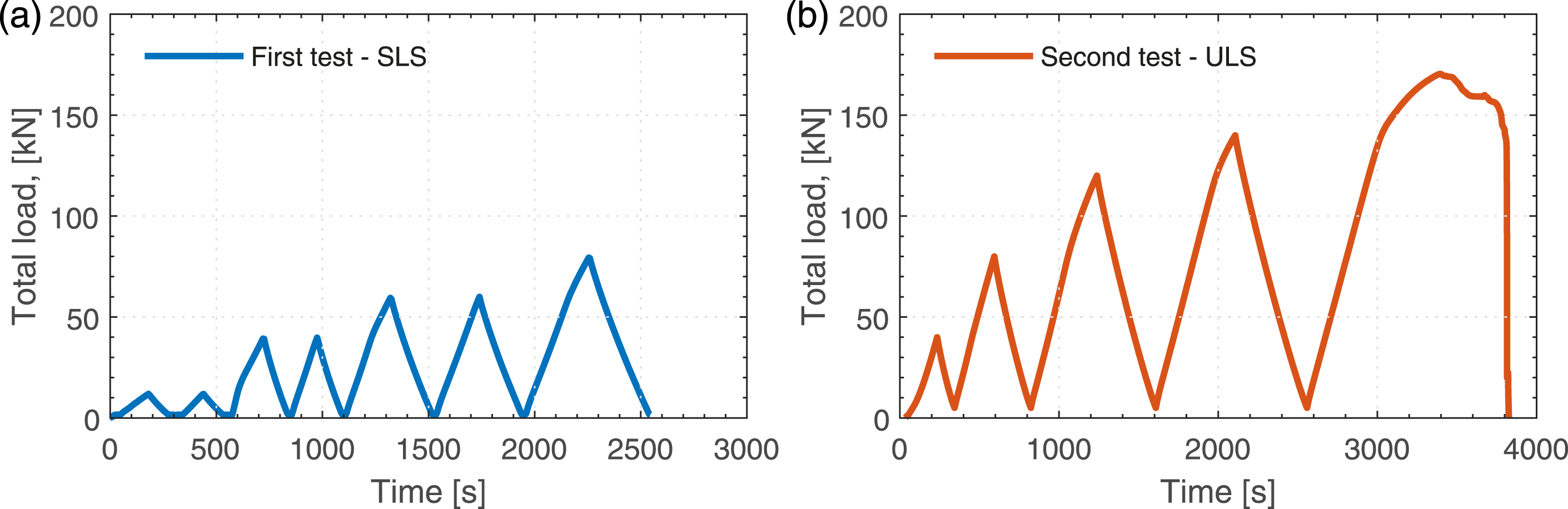
Characterisation of the stainless-steel mechanical properties
Using an MTS Universal Testing machine, the stainless steel used in this study was subjected to direct cyclic tensile loads, conducted up to failure. The steel quality for the bars used in the described beam, is of EN 1.4362, according to European standards. A length of 65 mm was clamped at each bar end, through which the load was directly applied to the bar. Total machine displacement as well as bar deformation were registered during the tests. The bar deformation was measured using an extensometer with a gauge length of 50 mm positioned at the middle of the bar.
Results and discussion
Stainless-steel mechanical properties
The results from the cyclic tensile test conducted on the stainless steel rebars, exemplified the characteristic behaviour of duplex stainless steel. The absence of a clear yielding stress, with the corresponding plateau before the hardening phase, which is commonly seen for carbon steel was observed. Conversely, the results display a smooth transition between the quasi-elastic and plastic phases of the material. However, the quasi-elastic phase of the material shows the presence of plastic deformation after the unloading of the bar, at virtually any stress level reached, see Figure 4. Further, such plastic deformation is observed to grow with the maximum stress level reached in the bar, indicating that the plastic deformation on the bar becomes more significant when the bar is subjected to higher stress levels. On the other hand, as shown in the detail of Figure 4, the plastic strain measured after two consecutive cycles of the same amplitude does not seem to vary, indicating that the material responds elastically for cycles of the same or lower amplitudes, being necessary to overcome the former maximum stress to develop a new and larger plastic strain on the material. Results of the material test conducted on stainless-steel bars used in this study: characteristic stress-strain curve for a tested bar and a detail of the quasi-elastic branch showing the small plastic strains due to cyclic loading.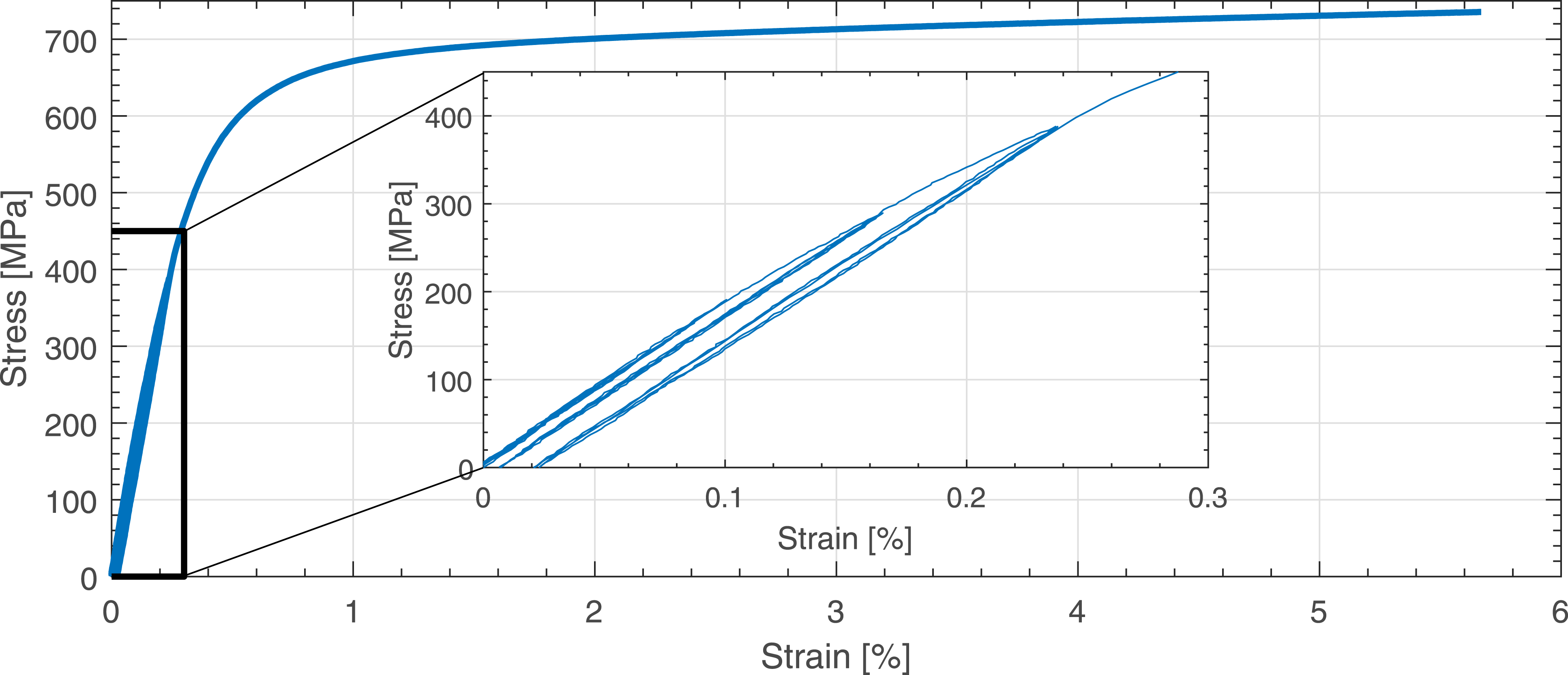
Distributed optical fibre sensor strain profiles in RC beams under four-point bending
As described in ref. 26, there are several factors that may have a significant impact on the robust/clad DOFS measurements when embedded in concrete. First, the non-uniform field of strains along the span of the beam will mobilize the shear response of the coating in the case of perfect bonding. Second, the appearance of cracks in the concrete will create steep strain gradients in the reinforcement bars. In that scenario, the strain transfer between the rebar and the DOFS would be sensitive to the properties and the thickness of the adhesive used as well as of the fibre coating/cladding. Nevertheless, both carving a notch along all the reinforcement bars in a structure to accommodate the DOFS and using adhesive to bond the DOFS to the rebar surface seem unpractical solutions in real-scale projects. Therefore, in this study clad DOFS were as well simply embedded in the concrete and fixed to the reinforcement with electrical tape, thereby providing strain measurements that might, in principle, differ from the clad DOFS embedded in the reinforcement notch. Furthermore, to study the possibilities and performance of clad DOFS applied to existing structures, the optic fibre cable was glued with a two-compound epoxy in previously made notches on the concrete surface. For this deployment method, the aforementioned effects are especially relevant since even larger strain differences can be expected at the crack position, leading to steeper strain gradients that can affect the measurements. These aspects are investigated in the following.
Analysis of DOFS strains
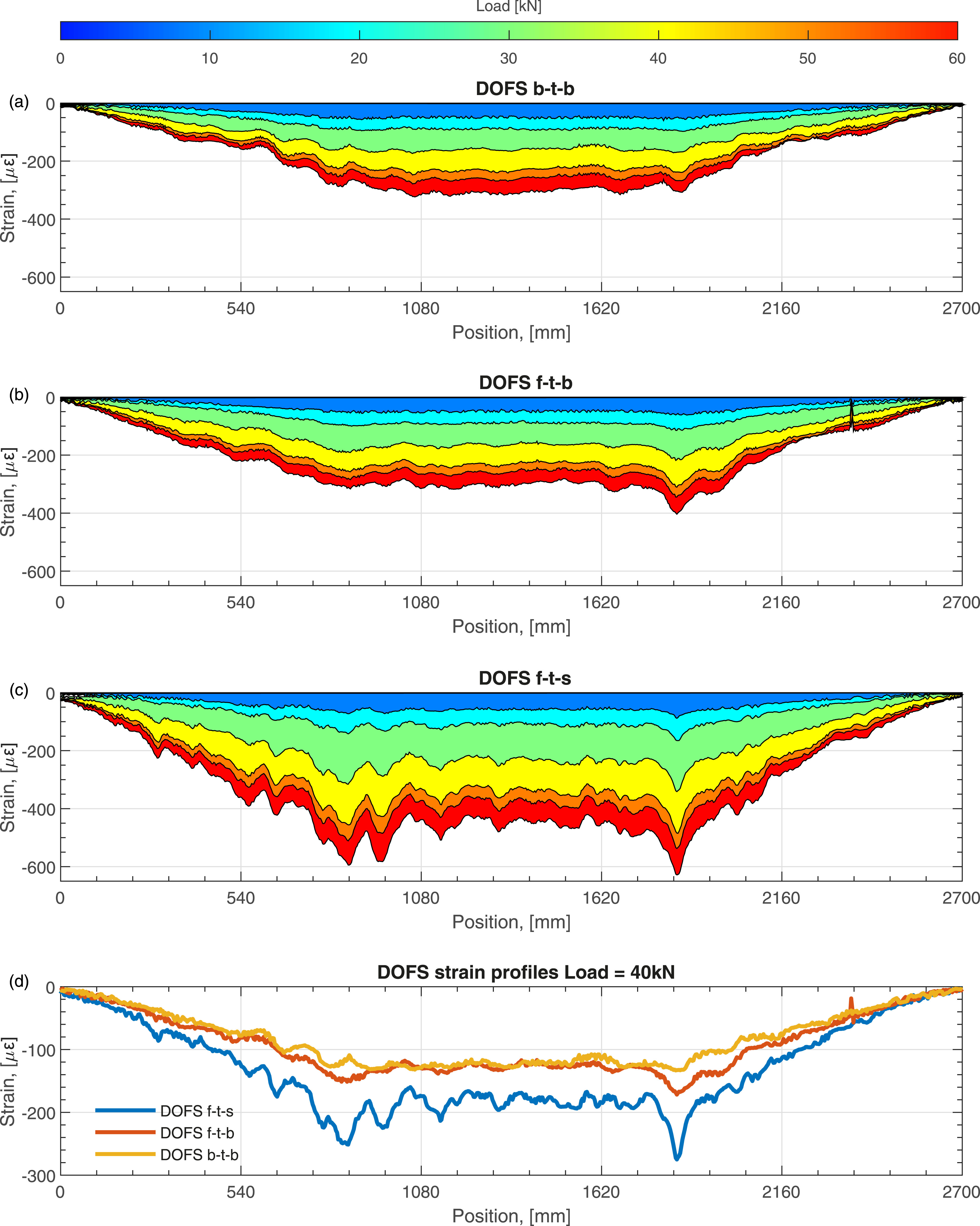
In Figure 5 and Figure 6, the strain profiles for six different positions of the clad DOFS in the beam are presented with increasing load levels and further compared between them for a load level of 40 kN. As expected according to classical beam theory, the magnitude of the strain is maximum for the DOFS positioned at bottom, Figure 5(a) to (c), and it decreases proportionally to the decrease in distance to the neutral axis, becoming negative for the DOFS positioned at the top reinforcement located in the compressive zone of the section, see Figure 6(a) to (c). Accordingly, the magnitude of the strains increases with the increase of load. In addition, the appearance of strain peaks evidences the formation of cracks, and they can be observed early in the loading process. Those peaks grow subsequently higher and more distinct with increasing load level. Comparison of distributed strain profiles obtained by DOFS embedded and attached on the concrete surface in the tensile zone. Comparison of distributed strain profiles obtained by DOFS embedded and attached on the concrete surface in the compression zone.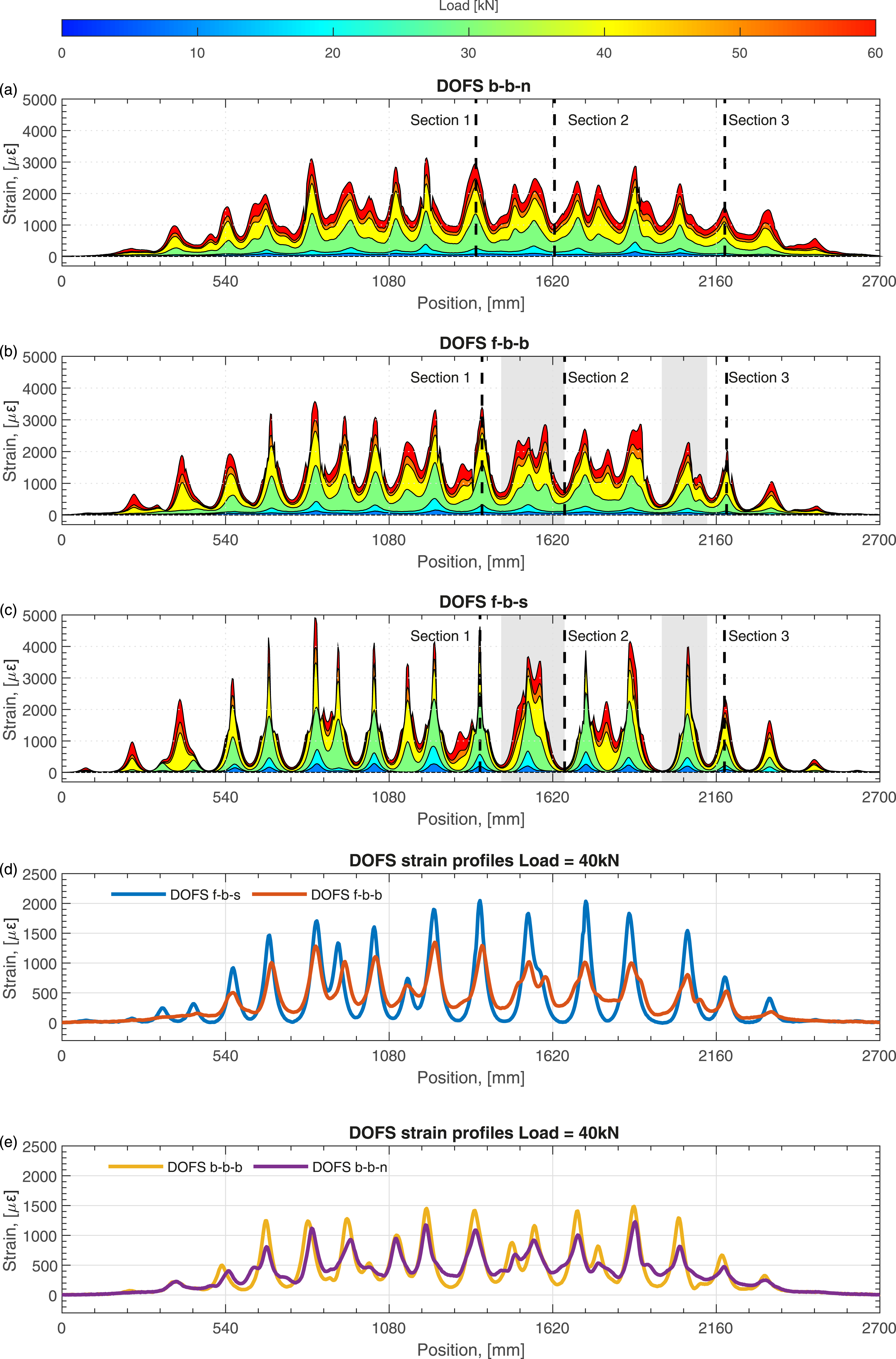
A closer look to Figure 5(a) to (c) reveals that obvious differences exist between the strain profiles measured by the DOFS depending on its position and attachment. A direct conclusion from Figure 5(c) is that positioning the sensor on the concrete surface after the concrete has hardened leads to more incipient peaks linked to the crack position. Moreover, when comparing such strain to any other measurement, that is, DOFS b-b-b and DOFS b-b-n, it can be seen that this concentration effect develops very rapidly with increasing load levels, being the strain magnitude in some cases double than for the DOFS placed at the notch (b-b-n). In addition, when comparing the DOFS f-b-s to the strain profile measured by the DOFS simply attached to the steel bar, DOFS f-b-b, for a certain load level, see Figure 5(d), it can be seen that the strain measured between consecutive peaks, is of lower magnitude, being this effect more noticeable at the valley, indicating that the DOFS f-b-s strain is closer to the concrete strain while the strain measured by the DOFS f-b-b is closer to the actual strain in the bar. Similar differences but to a lower extent can be observed in Figure 5(e), for the sensor attached to the bar and the sensor embedded in the notch, namely, b-b-b and b-b-n, respectively, where the latter is expected to measure a strain even closer to the actual steel strain while the former is expected to show an in-between measurement concrete/steel strain.
The observation of different crack patterns on the front and back sides of the beam is confirmed when comparing the strain profiles of b-b-n, f-b-b and f-b-s DOFS, Figure 5(a) to (c) respectively. Likewise, differences in crack patterns between sensors deployed on the same side, namely, f-b-s and f-b-b DOFS, are also denoted. Even though the majority of the strain peaks are located at a similar position, in some cases the strains measured on the surface or inside do not completely agree, indicating that occasionally two cracks observed on the surface may convolute into one before reaching the bar and conversely, two cracks at the bar level can merge before reaching the surface. This can be seen, for instance, at the shaded zones indicated in Figure 5(b) and (c), between 1500–1600 m and 2000–2100 mm.
Similar principles are observed when looking at Figure 6(a) to (c). However, as the DOFS are placed in the beam’s compression zone, the effect of cracking is not as perceptible compared to the corresponding measurements from the DOFS placed on the tensile zone. Still, a wavy shape for the strain measurements can be observed denoting the variation of strains due to the presence of cracks; hence, the change of the neutral axis position between cracked/uncracked zones. The comparison between the DOFS measurements of the different positions, inside and outside the concrete, see Figure 6(d), clearly indicates that, once more, the DOFS attached to the concrete surface is more sensitive to strain variations, depicting larger variations of strain between cracked/uncracked zones and being the measured strain between cracks closer to the concrete strain. The later can be argued by the presence of two remarkable peaks in the measurements. Those peaks occurred under the point loads; therefore, it is expected that the concrete under such regions describes larger longitudinal strains due to the loading plate pressure introduced by the load in the beam.
A further comparison of the tensile strain measurements is presented in Figure 7, where the strain of two sections, namely,
Introduction
and
Experimental Programme
in Figure 5(a) to (c) corresponding to a crack and a valley, respectively, are shown during the entire loading process of the beam. A first observation is that in both cases the measured strains follow the load introduced in the beam, see Figure 3(a), increasing its value with increasing load and decreasing it with decreasing load, independently of the position of the sensor. However, it is as well very clear that the position of the sensor strongly influences the obtained measurement, being the DOFS f-b-s the one giving largest strain values at
Introduction
, cracked, and the DOFS b-b-n the lowest. Conversely, the measurement at the valley yields the opposite behaviour, being the strain measured by DOFS b-b-n the largest and the strain measured by the surface DOFS the smallest. Obviously, this observation is in line with previous observations made, which already indicated this difference of behaviour between cable positions. Nevertheless, a very interesting remark from Figure 7(a) and (b) is that the DOFS is able to accurately capture the plastic deformation occurred in the steel bar, even between cracks where the strain level reached is significantly smaller. This plastic strain, as previously described in the material characterisation, occurs already for very low stress/strain levels, and the sensor, regardless of its position in the beam, can capture it. Strain evolution in time for Introduction section and Experimental programme section indicated in Figure 5(a)–(c), that is, crack and valley, respectively.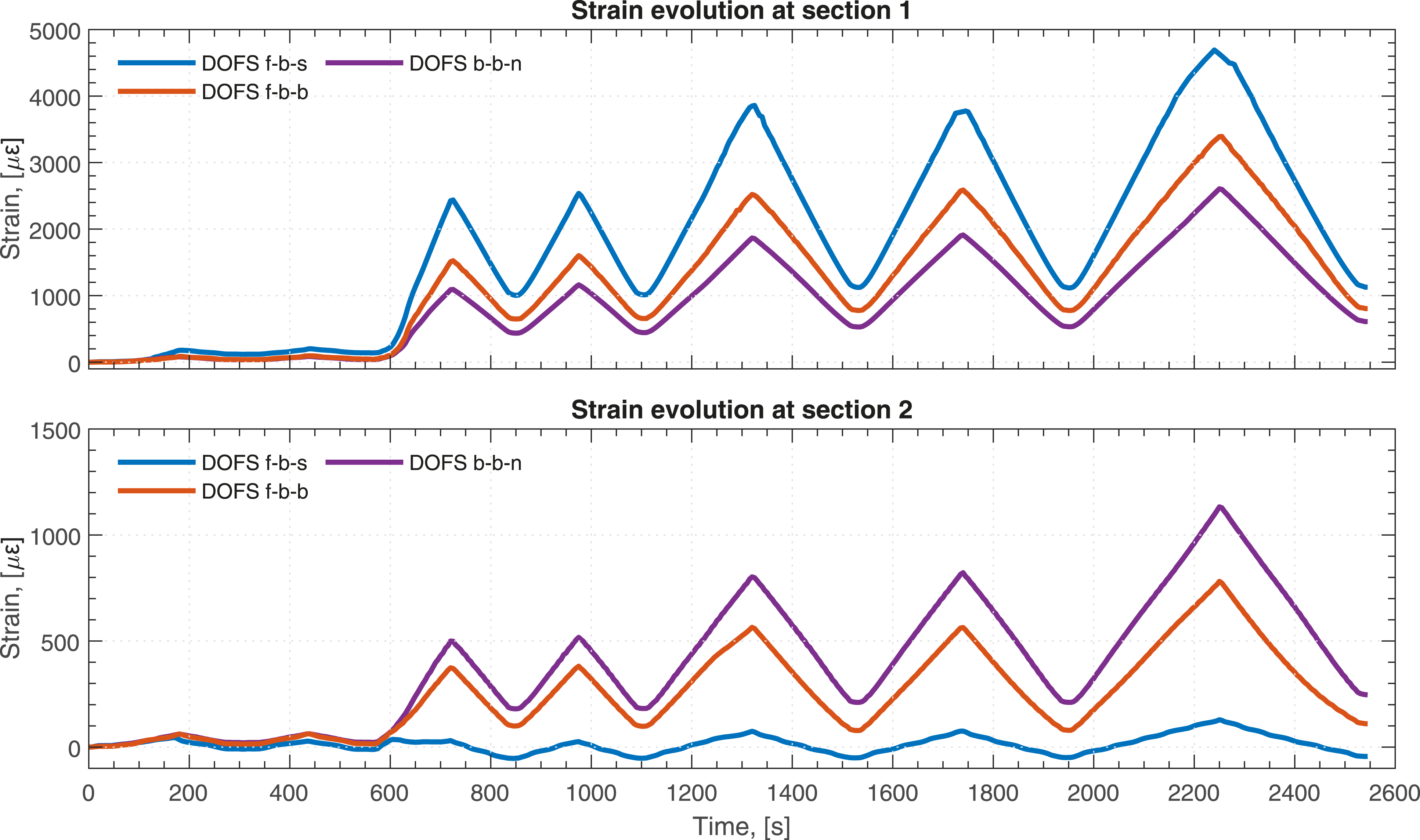
Assessment of bending cracks
In this section, the ability of DOFS, placed at different locations, to simultaneously identify the position and calculate the width of multiple cracks in RC beams subjected to bending is investigated.
Locations of cracks
As previously shown in DOFS Strain Profiles in Reinforced Concrete Beams under Four-Point Bending, the distributed nature of the strain measurements based on Rayleigh scattering provides a straightforward way to identify the position of cracks, which appear as well-defined peaks in the strain profile. In addition, as already shown in previous studies, robust DOFS embedded do not require complex post-processing algorithms to analyse the strain data thanks to their smoother signal output. The same conclusions can be formulated for the sensor used in this work, the clad DOFS V1, despite the absence of the protective steel mesh compared to the V9. 26 Thus, the crack locations can be unequivocally identified as the local maxima in the strain profiles measured by the DOFS.
To show the ability of DOFS for detecting cracks, the strain profiles of the beam measured by DOFS f-b-b and DOFS f-b-s for one load level, namely, 80 kN, are shown in Figure 8. It can be seen that the locations of the crack candidates, that is, those corresponding to strain peaks, have been identified based on the strain profile of DOFS f-b-s. In the same figure, a picture of the 2D strain field computed by the DIC at the same load level has also been added as an overlay to show the actual crack pattern on the concrete surface. Additionally, the (re-scaled) surface strains along a horizontal line at the height of the DOFS cable (f-b-s), obtained from the DIC, have been drawn in the same plot to facilitate the comparison of the crack locations. Location of individual cracks based on DOFS strain profiles and comparison with the crack pattern identified by the strain field from measured with DIC. Note that DIC strains are re-scaled and plotted solely to illustrate the location of the cracks.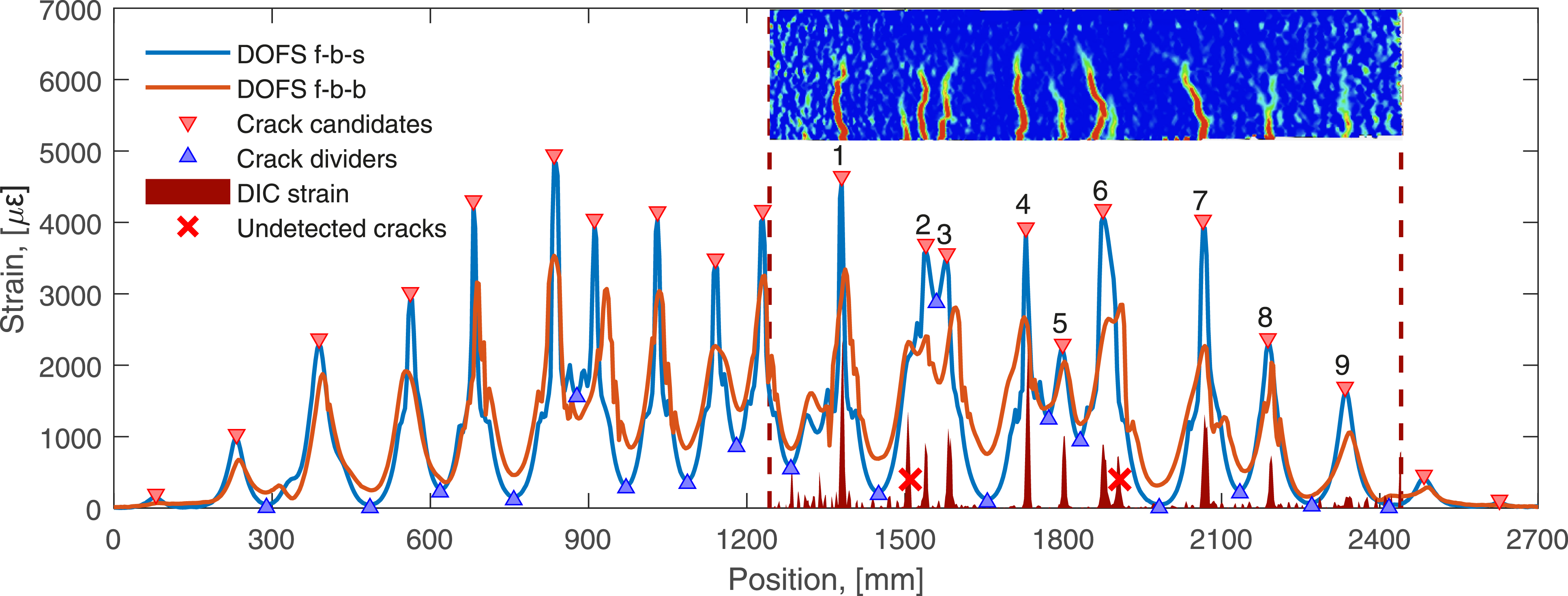
From Figure 8, it can be observed that 10 distinct cracks were formed on the concrete surface based on the DIC strain field, whereas only 9 crack candidates could be identified within the DIC measurement region by both DOFS presented. The disagreement between DIC and DOFS measurements is mainly due to the fact that for some cracks DOFS strain measurements displayed a convoluted strain peak instead of two distinct peaks. This observation is even valid for DOFS measurements performed on the concrete surface, in spite of the increased capacity to accurately detect crack positions, due to more prominent strain peaks at the crack location. In addition, the differences observed between DOFS f-b-s and DOFS f-b-b indicates that the crack formation process differs between the surface and the inside where cracks can grow in different ways from the outside to the inside and from the inside to the outside. Further, in line with previous observations, when using robust DOFS embedded in concrete, 26 it is advisable as well for DOFS attached on the surface to perform the crack detection as a recurrent process taking into account the load history in order to identify when the strain rise of a new forming crack merges with the strain peak of an already existing crack thereby hindering their individual identification.
Measurement of crack widths
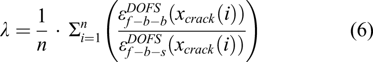
The approach proposed by the authors of ref. 24 and further developed by the authors of refs. 25 and 26 is used in this section to measure crack widths from the different strain measurements. Therefore, the crack width of individual bending cracks can be calculated with an accuracy of ± 20 µm based on the strain measured by the DOFS at the tensile reinforcement according to equation (1)
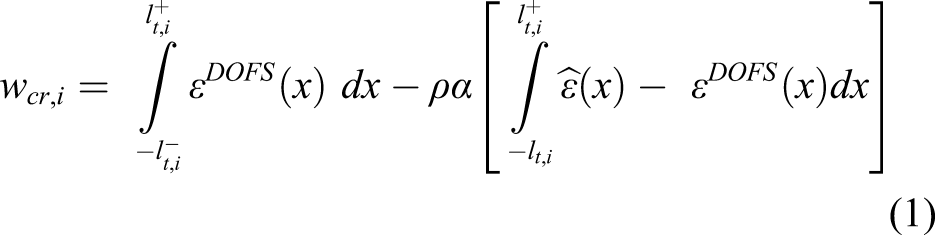
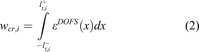
This simplification should yield reasonable results and an upper limit of the crack width, being the actual crack width equal or smaller, depending on the real contribution of the surrounding concrete. Based on the described method, the evolution of crack width in time for the different identified cracks in Figure 8 is plotted in Figure 9 where a comparison of the crack width calculated from the different DOFS front measurements, that is, DOFS f-b-s and DOFS f-b-b and lastly DIC is presented. Comparison of crack width computed by DOFS strains and measured by DIC for the cracks identified in Figure 8.
As observed in Figure 9, the proposed method and the corresponding simplification can be used to determine the crack width at different position using DOFS regardless of its placement. However, it is worth noting that for large crack widths the integration of the DOFS f-b-s may lead to some attenuation, which can result in a lower crack width than expected compared to DIC or DOFS f-b-b, for example, crack 1, crack 4 and crack 7. Additional discussion on this phenomenon is provided in later sections. From crack 5, it can be confirmed that the cracking occurs differently in the inside and outside of the element. In this particular case, the crack starts developing at the bar and subsequently grows to the surface. As a consequence, the crack width measured by the DOFS f-b-b yields larger crack width than both the DOFS f-b-s and the DIC. Furthermore, from crack 9 it is clearly seen that the capacity and accuracy for quantifying the crack width of DOFS is better than the DIC, which for very low crack width and positions close to the image edges yields values with a lot of noise.
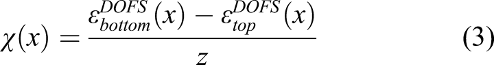
Assessment of beam deflections
In this work, deflections were calculated through the double integration of the curvatures as defined by equation (3) Comparison of deflections computed by DOFS strains and measured by DIC (a) and their corresponding absolute and relative errors (b–c) with respect to the DIC.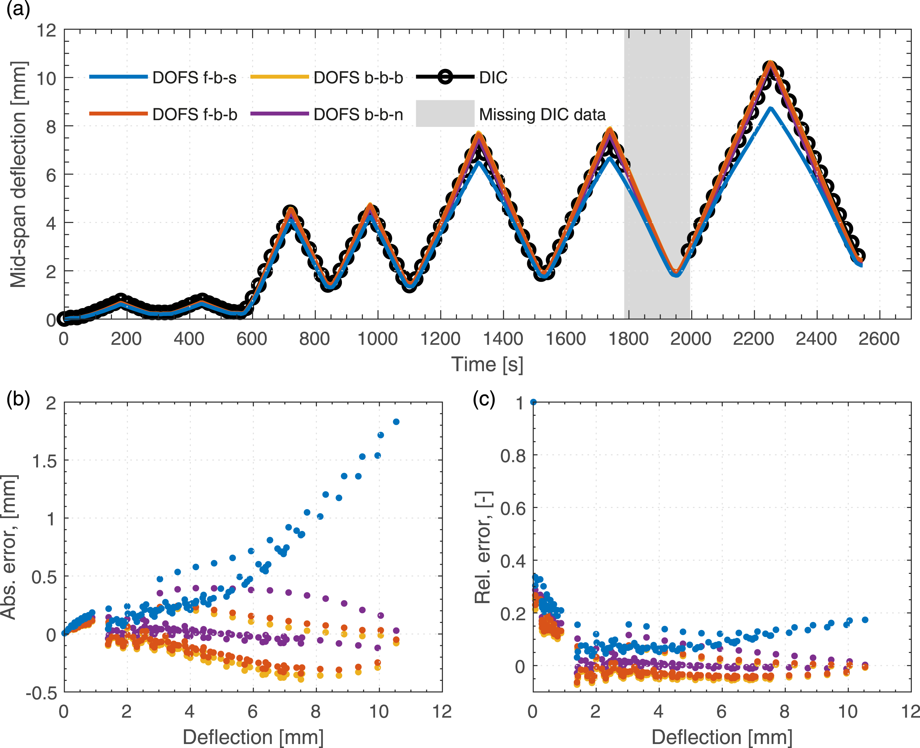
Overall, the deflections calculated by the DOFS showed a consistent agreement with the DIC measurements, except for the DOFS placed on the concrete surface that systematically underestimated the calculated deflection for values exceeding 4 mm of deflection. The maximum absolute error was found to increase with increasing deflection in all cases, reaching a maximum of about 2 mm for the DOFS f-b-s. In relative terms, however, it can be seen how the error is very large at small deflections, basically before concrete cracking. For embedded DOFS, it decreases rapidly with increasing deflection, reaching relative errors close to 0%. Conversely, after an initial reduction of the relative error for the surface DOFS, the relative error grew rapidly after the deflections exceeded a value of 4 mm, reaching up to 20%, which is a direct consequence of the attenuated values seen for large deflections.
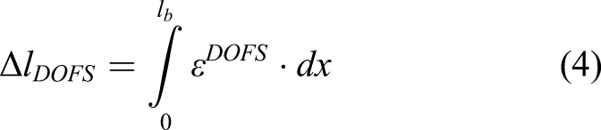
In order to understand the observed differences in both the deflection and the crack width calculated with DOFS f-b-s compared to either DIC or embedded DOFS, the total elongation of the fibre optic cable for the different positions is calculated as Elongation of the DOFS cable at different positions.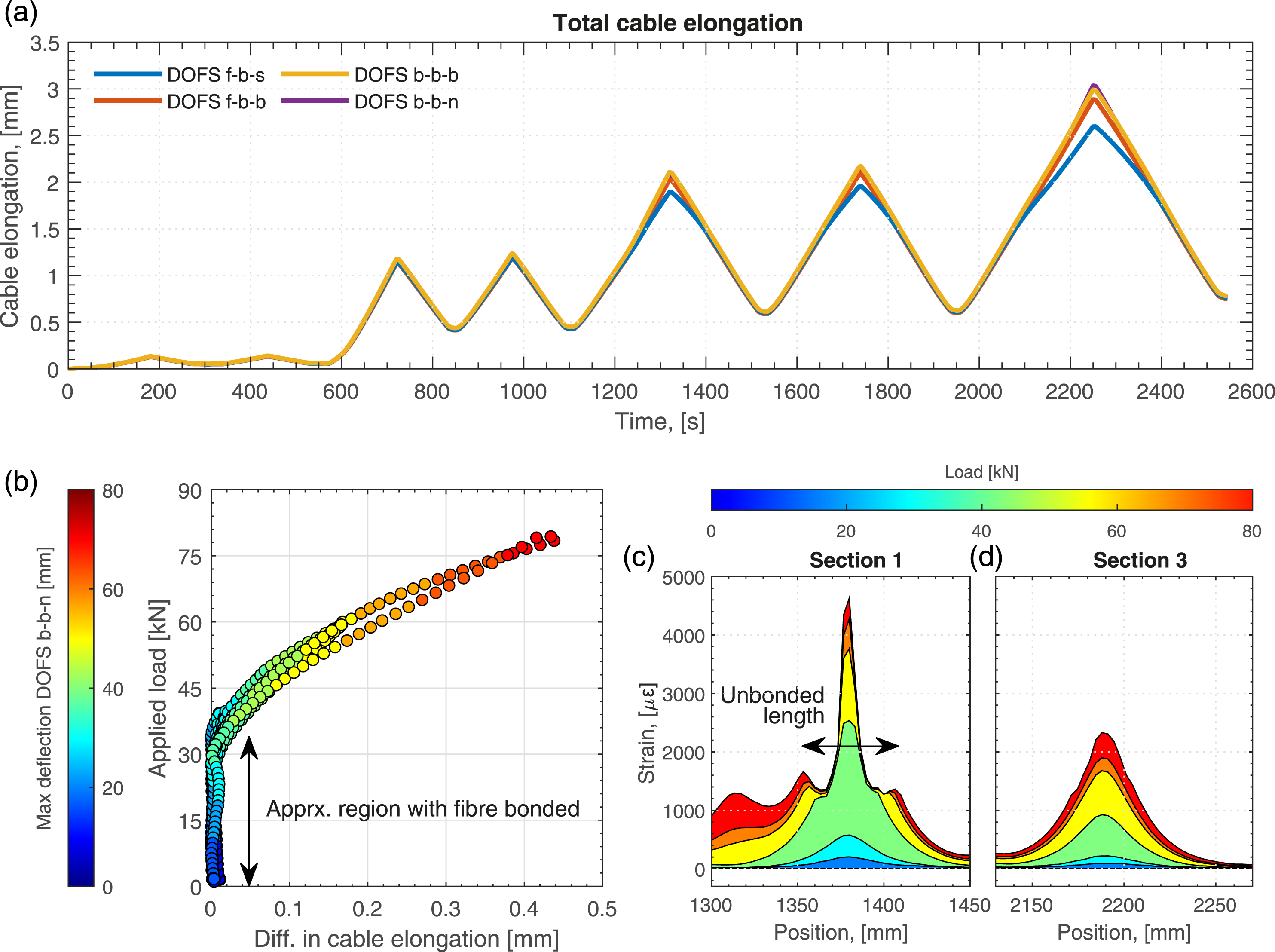
A possible explanation that clarifies the presented observations is that a loss of adhesion between the fibre and the concrete occurred, most likely at the cracks, due to high strain concentration. To further validate this assumption, a detailed view of the measured strains by DOFS f-b-s at Introduction and Results and Discussion for different load levels described in Figure 5(c) is illustrated in Figure 11(c) and (d). As it can be noted the shape of the strain between consecutive valleys is very similar for the two selected sections up to around 40 kN, describing a continuous strain field. Moreover, the portrayed shapes are in agreement with observations made for the DOFS embedded in other positions. Nonetheless, as soon as the applied load overcomes this magnitude, the shape of the strains is meaningfully affected and the strain peak significantly contracts losing the described natural continuity of the strains between valley and peak, and even describing a slight reduction of strain before a very abrupt increase. The described length of disturbed strain to the left and right of the crack is estimated to be the length of cable that loses adhesion with the concrete, see Figure 11(c). Further, if the elongation of the cable for Introduction and Results and Discussion is now compared to each other, namely, crack 1 and crack 8 in Figure 9, it can be clearly seen that the DOFS f-b-s is in perfect agreement for crack 8, but not for crack 1, due the aforementioned loss of adhesion and the subsequent loss of strain continuity.
A further analysis is shown in Figure 11(b), which describes the difference of elongation between DOFS f-b-s and DOFS b-b-n, that is assumed to be the most accurate measurement due to its deployment in the notch, with respect to the applied load. The colours of the markers indicate the maximum deflection calculated by DOFS b-n-n for each corresponding load level. Two important observations can be made; first, the load threshold for which exists a fairly good compatibility between surrounding material and sensor is validated to be approximately 40 kN, below such value no appreciation of loss of adhesion is seen. This happened consistently for all cycles, indicating that even though the glue was probably broken in the first cycle, still a certain load level was needed to break the adhesion of the fibre due to natural friction with the surrounding material and develop slips. Second, once this load level is exceeded, the difference between cable elongations and, consequently, the loss of adhesion of DOFS f-b-s, increases non-linearly with both load and deflection.
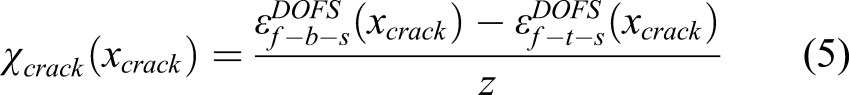
Correction methods for the calculation of deflections by clad DOFS on concrete surface
In order to obtain a more accurate estimation of the beam deflection using DOFS attached on the concrete surface, or at least values that are on the safe side, three different alternative methods are proposed and presented in Figure 12(a) to (f). The first and more conservative method assumes that the contribution of the uncracked sections of the beam is not significant and therefore, the beam deflection is governed by the curvature at the cracks. Accordingly, the calculation of the curvatures can be expressed as Comparison of deflections computed by DOFS strains and measured by DIC for beams 1, 2 and 3 (a–c) and their corresponding absolute and relative errors (d–f) with respect to the DIC.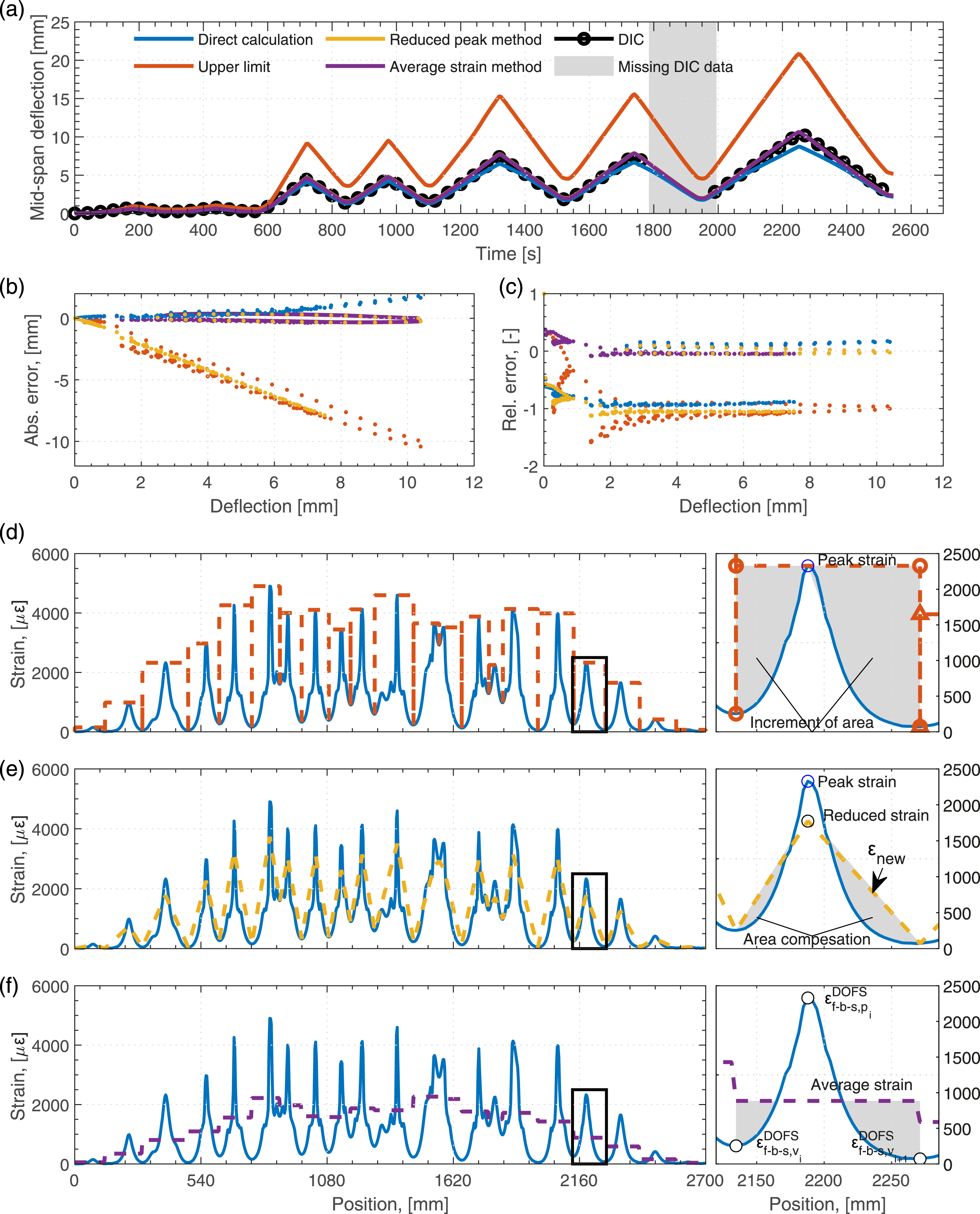

If
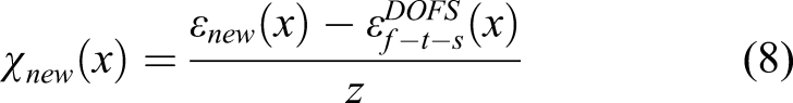
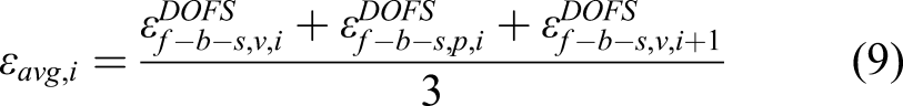
An additional method, intended to be independent of the measurements from DOFS at any other position but at the concrete surface is proposed. This method consists in assuming a uniform value of the strain between consecutive valleys that is calculates as
Performance of DOFS under high strains
An important limitation of the use of DOFS in RC structures is that due to the crack formation process, natural to the material, strain concentrations can occur and subsequently a loss of measuring capacity. That is not the case of other continuous materials where the strain levels are expected to be uninterrupted in the media and easier to measure for such type of sensors. This issue becomes even more relevant if the sensor is directly attached to the concrete surface since, as it has been previously shown, the concentration of strain in the cracks is much more pronounced. In Figure 13 the strain filed measured by DOFS at the different locations, that is, DOFS b-b-n, DOFS b-b-b and DOFS f-b-s, is plotted for the central moment zone of the beam with respect to time, for the loading process of the beam to failure according to Figure 3(b). It must be noted that DOFS did not give strain values for a load higher than 140 kN, as indicated in Figure 13(a). (a) Applied load to failure, (b–d) strain fields measured by DOFS in the constant bending moment zone, (e) strain in time for crack 4 in Figure 9.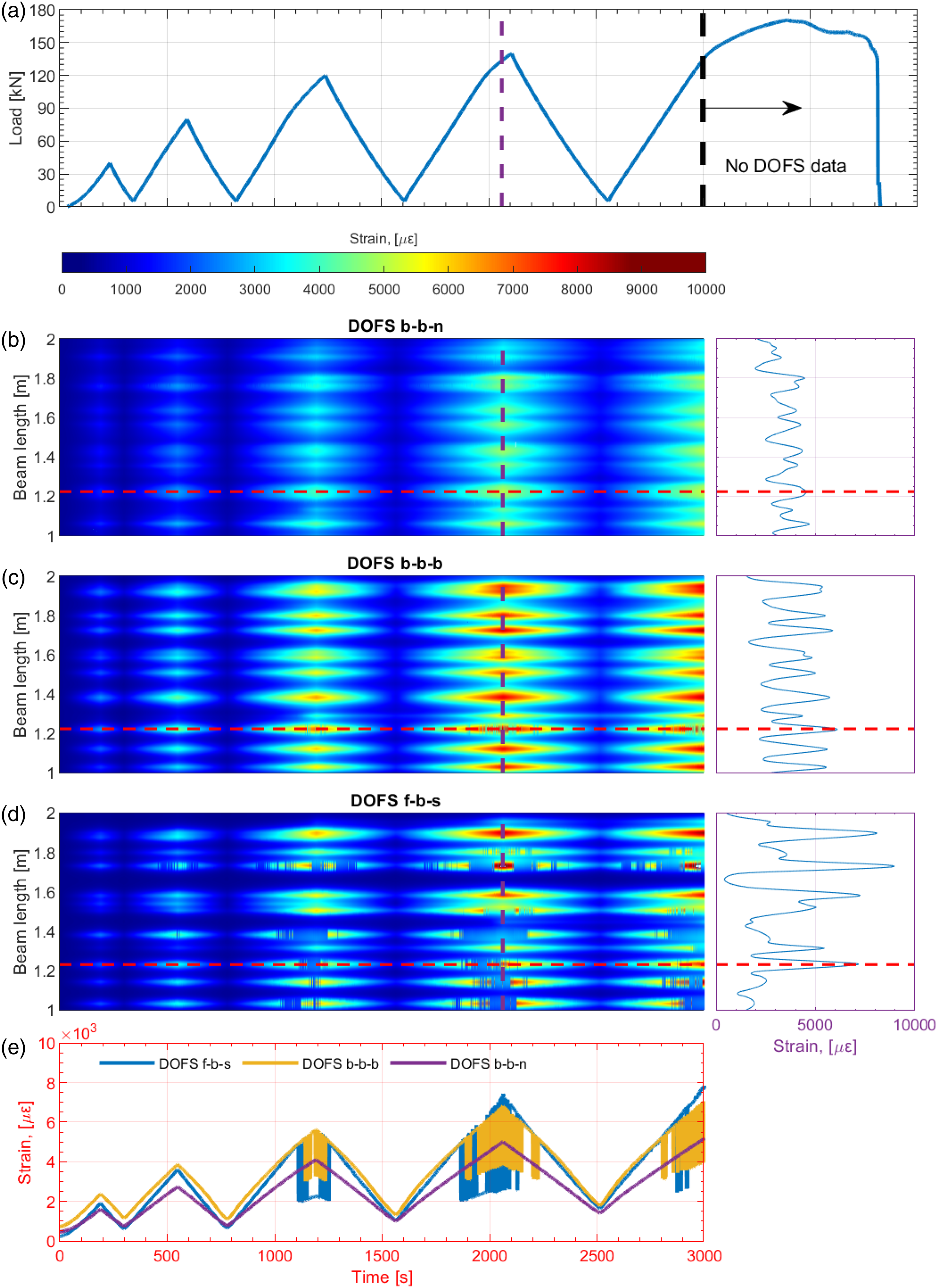
Several observations can be made from Figure 13. The strain fields depicted by embedded DOFS are similar regardless to the load level, presenting both positions continuous strain values in time and space. It is worth noting that one of the cracks, crack 4 in Figure 8, describes some loss of data in time for the DOFS b-b-b, most likely due to large crack widths occurring there. The DOFS b-b-n presents a clear description of the strains both in time and space. Conversely, the strain field depicted by the DOFS f-b-s shows obvious spatial and temporal absence of strain data for already very low load levels. This absence of data clearly increases with increasing load level, presenting important gaps in several regions of the sensor for load levels around 120 kN or above. Moreover, the presence of gaps in the collected data for load levels beyond 140 kN was excessively extensive which made it impossible to reconstruct any strain profile and, therefore, further evaluate the structural behaviour. It is worth noticing that the failure load level was for this particular beam around 170 kN, being the DOFS able to yield trustworthy measurements up 80% of the ultimate load.
Despite of the observations presented in Figure 13, as shown in Figure 14 the collected data was still enough to allow for the calculation of the beam deflection with good accuracy. On top of that, once the load goes under the threshold for which the DOFS yielded significant absence of reading, the measurements are again clear and in good agreement to the DIC, which indicates a good robustness of the sensor. Comparison of deflections computed by DOFS strains and measured by DIC for cracks 1, 2 and 3 (a–c) and their corresponding absolute and relative errors (b–c) with respect to the DIC.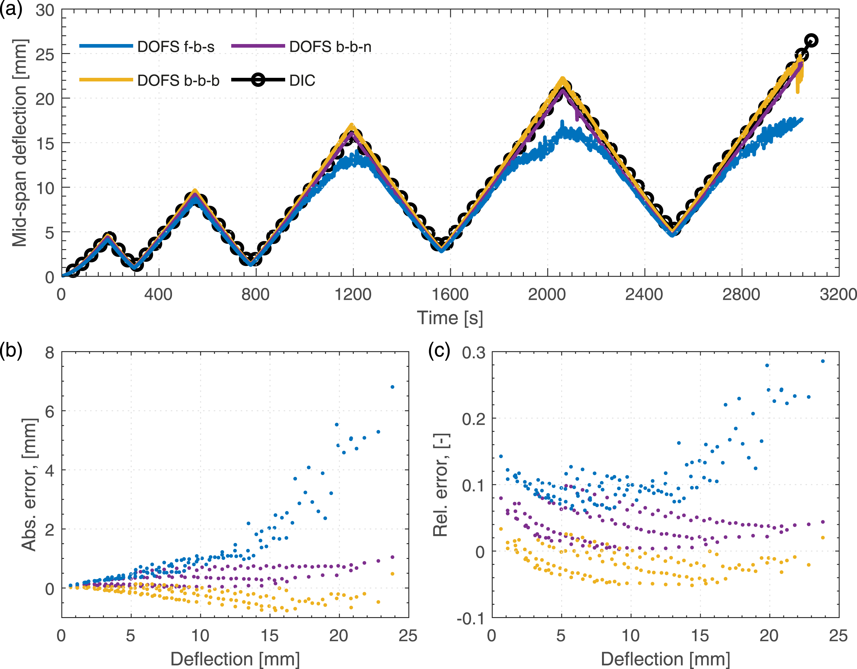
Conclusions
This article investigated the performance of clad DOFS based on Rayleigh backscattering for the monitoring of strains in RC structures as well as its applicability for the monitoring of existing structures by using sensors attached to the concrete surface after casting. A beam was cast with a clad fibre optic cable deployed in a multi-layer configuration and the beam was subjected to cycling loads for both service and ultimate loads while continuously monitored. The main conclusions drawn from this study are the following: • The clad DOFS described strain fields without the characteristic anomalies shown by polyimide-coated fibres used in many other studies. No significant differences are observed between the sensor employed in this study, the clad V1 fibre optic, compared to other more robust alternatives such as the steel reinforced V9 sensor. • The strain profiles showed evident differences depending on the DOFS position. DOFS embedded in the steel bar notch depicted a smoother description of the strains, showing both higher strains at valleys and lower strains at peaks. Conversely, DOFS attached to the concrete surface, yielded high strain values at the cracks and very low at the valleys, being the later closer to the actual concrete strain. • Regardless to the deployment position, the clad sensor showed a very good capacity to describe the structure behaviour, even recording very small plastic deformations that occurred on the stainless-steel reinforcement, regardless of its position in the beam. • The crack detection with the DOFS f-b-s seemed to be easier thanks to the pronounced strain peaks due to the concentration effect. However, similar issues as for other sensors were detected: secondary late cracks may grow close to an existing one, leading to a convoluted strain peak that prevents the distinction of two individual cracks. Therefore, the strain history must as well be considered. • Using DIC as a reference, it was demonstrated that the values of deflection and crack widths calculated based on the measured DOFS strains were shown to be very accurate for service loads and embedded sensors. However, DOFS attached to the surface yielded slightly deviated values for both crack width measurements and deflections. A further investigation of such deviations concluded that beyond a certain load level the sensor was detached from the concrete losing adhesion thereby describing attenuated values of the measured strains. The impact of such behaviour was shown to be more significant for the calculation of deflections, which were systematically underestimated, compared to the crack widths where only a few of them were affected by this issue. Two methods were proposed to correct the DOFS surface measurements for the deflection calculation and obtain values as accurate as for the embedded DOFS, under service loads. • The use of clad DOFS for load levels above service range is only recommended when the sensor is embedded in a notch in the bar, which showed very accurate values in its measurements up to 80% of the ultimate load. The DOFS attached to the surface described important gaps of strain measurements both in the spatial and temporal domains, which prevented calculating trustworthy values for the deflections beyond service loads.
In general, the use of clad DOFS V1 embedded in the concrete described a good performance for the monitoring of RC structures both in service and ultimate loads. The use of V1 to monitor existing structures is more delicate, moreover due to problems with the sensor detachment at low load levels, close or slightly under service loads. Even though methods to correct and therefore calculate trustworthy values for the deflections were presented, alternative sensor solutions, such as V9, should be explored to mitigate the debonding effect and minimize the loss of data under high-load levels, in exchange of losing some accuracy in the results and a more costly deployment due to its high stiffness.
Footnotes
Acknowledgements
The authors would like to acknowledge the contribution of the company Outokumpu for providing manufacturing and providing the stain-less steel used in this work.
Declaration of conflicting interests
The authors(s) declared no potential conflicts of interest with respect to the research, authorship and/or publication of this article.
Funding
The author(s) disclosed receipt of the following financial support for the research, authorship, and/or publication of this article: This research has been performed as part of the project: ‘Sensor-driven cloud-based strategies for infrastructure Management – SensIT’ funded by the Swedish Transport Administration (Trafikverket) under the grant TRV/BBT 2017-028.
Data availability
The data generated in this work con be accessed and download under Open Data Commons Public Domain Dedication and License (PDDDL 1.0) agreement, from the “Svensk nationell datatjänst” (SND) public servers. 43