
Abstract
Marine Dual Fuel engines have been proved an attractive solution to improve the shipping industry sustainability and environmental footprint. Compared to the conventional diesel engines, the use of additional components to accommodate the natural gas feeding is associated with several safety implications. To ensure the engine safe operation, appropriate engine control and safety systems are of vital importance, whilst potential safety implications due to sensors and actuators faults or failures must be considered. This study aims at investigating the safety issues of a marine dual fuel (DF) engine considering critical operating scenarios, which are identified by employing a Failure Mode, Effects and Criticality Analysis. An existing verified digital twin (DT) of the investigated DF engine, capable of predicting the engine response at steady state and transient conditions with sufficient accuracy is employed to simulate the engine operation for the identified scenarios. The simulated scenarios results analysis is used to support the risk priority number assessment and identify the potential safety implications by considering the manufacturer alarm limits. Appropriate measures are recommended for the investigated DF engine safety performance improvement. This study demonstrates a methodology integrating existing safety methods with state-of-the-art simulation tools for facilitating and enhancing the safety assessment process of marine DF engines considering both steady state conditions and transient operation with main focus on switching operating modes.
Keywords
Introduction
Background
The maritime industry is a significant contributor to the global greenhouse gas emissions accounting for 3.5−4% of the worldwide carbon dioxide (CO2) emissions. 1 To mitigate the air pollution impact of the maritime industry, a series of regulations for non-greenhouse gaseous emissions including nitrogen oxides (NOx) and sulphur oxides (SOx), as well as greenhouse gas emissions have been enforced by the International Maritime Organisation (IMO), 2 the European Union (EU) 3 and the United States Environmental Protection Agency (EPA). 4
Responding to the imposed regulatory framework, the use of marine dual fuel (DF) engines are considered as an attractive solution,5–8 as they can achieve high output whilst combining fuel flexibility, low emissions, high efficiency and reliability. These engines can typically operate at either the gas or diesel modes, as well as the shared fuel mode, where both gas and diesel fuels can be used in defined percentages. The marine DF engines typically run under steady state conditions using the same fuel type, although relatively slight power demand fluctuations may occur due to vessel weather conditions changes. Switching to a different mode needs to be implemented either when the vessel approaches or leaves Exhaust Control Areas (ECAs) or when a failure occurs in the fuel systems and their components, that is, pressure loss of the natural gas fuel supply. 9 In this respect, the engine manufacturers ensure smooth and reliable operation quantifying the interactions between the engine components during both steady and transient conditions, including operating modes switching. Apart from ensuring these engines operation at the highest efficiency and the lowest emissions, it is a prerequisite to ascertain their safe operation.
Safety is defined as the state where a system operates without causing any harm to humans, environment and assets. 10 When considering the marine engines safety, it can be inferred that the environmental aspect is related to the airborne emissions, whereas the human safety aspect can be jeopardised either by exposure to engine emissions or to hazards owing to engine components failures or faulty operation. The NOx and PM emissions generated during the combustion process have been proven to be harmful for human health, thus increasing the potential for human deceases in the area of operation. 11 Asset-related risks may negatively impact the humans’ safety, considering the additional hazards induced by marine DF engines, when their safe operation is not ensured (for example, in cases of fires, explosive environment, gases leakages, etc.).
Hence, industrial standards (IACS unified requirements, 12 IGF 13 and ICG 14 Code, IEC, 15 European Commission directive (ATEX) 16 and SOLAS Convention 17 ) have been established to ensure that the engine manufacturers develop environmentally sound, reliable and safe engines by taking into account all the potential hazards that may occur during the engine operation. The identification and qualitative or quantitative risk assessment are therefore crucial. Moreover, the additional risks introduced by the gas fuel utilisation in marine DF engines, are addressed by supplementary assessments, mainly described in the gas safety concept reports. 18
Even though these engines operate at acceptable safety levels and demonstrate satisfactory reliability, there is space for further improvement of the engine safety system by accommodating cutting-edge technological advancements, as discussed in the following sections.
Marine diesel/DF engines design and operational hazards
Comparing the marine DF engines with the conventional marine diesel engines, a number of additional components is introduced. These components and their associated functionalities may lead to new hazards and unpredicted hazardous interactions of the engine sub-systems, unless properly handled.19,20
In marine diesel engines, the hazardous situations include conditions such as high oil mist concentration in the engine crankcase, turbocharger (T/C) compressor surging, diesel engine camshaft overloading, inadequate lubrication, cooling and fuel supply, increased or fluctuating thermal loading and sudden engine tripping, which under worst case scenarios, may lead to high risk engine operating conditions.21,22 For instance, component faults or failures in the auxiliary systems of a diesel engine may lead to engine inappropriate cooling, lubricating and fuelling.23,24 Other failures leading to hazardous situations include the engine components health deterioration, such as piston rings, stuffing boxes, fuel injection system and air filters.23,25,26 Furthermore, hazardous situations may also be associated with either the engine sensors and/or actuators faulty operation or the engine control hardware malfunctioning, demonstrating more severe impact when the engine operates at high loads. With regard to the engine sensors, common issues may be associated with the charge air/exhaust gases pressure or temperature sensors, 27 the engine speed and crank angle sensors,27–29 as well as the engine lubricating oil and charge air coolant pressure or temperature sensors. The actuators faults may be related to the diesel fuel rack actuator and the diesel fuel injectors (misfire issues) 30 as well as the valves clearance. 31 Less common are the issues occurring due to malfunctions/failures of the engine control system software and hardware, which exhibit major impact on the engine operation and therefore must not be neglected.
Marine DF engines operate with additional inherent hazards such as, knocking and T/C compressor surging during transients.32,33 Deviations from the expected ranges of the engine performance parameters may trigger the engine safety functions, such as gas trip (emergency fuel change from gas to diesel), slowdown or even shutdown, which may render the engine temporarily unavailable. This may lead to system-level hazardous conditions including the ship position loss or a total blackout; both are associated with a risk for collision, contact or grounding accidents. 34 The ship-board storage and use of natural gas increase the risk for fire and explosion accidents.35,36 Hazardous situations in marine DF engines are also associated with the engine sensors and/or actuators faulty operation. In specific, the gas (fuel) manifold pressure sensor, the Gas valve Unit (GVU) as well as the Gas Admission Valve (GAV) actuator are considered safety-critical components, as their potential faults can significantly affect the engine control response, and therefore the engine operation in the gas mode. Moreover, the exhaust waste gate (EWG) system is also of vital importance, as an EWG valve actuator potential failure may lead to turbocharger overspeed, which is associated with several hazardous scenarios for the engine, ship and crew. Lastly, the engine control system is classified as safety-critical, due to its fundamental impact on the fuels control (i.e. type of fuel, injected fuel amount). Therefore, despite the fact that marine DF engines are considered vastly reliable, are still prone to component failures or faulty conditions due to either hardware or software deficiencies/issues (minor and rarely major issues).37,38
The failure modes of the engine control systems are associated with the failures of either sensors or actuators. Sensors can respond by giving erroneous measurements in terms of offset, drifting, bias and gain errors25,39–42 or by giving zero output. Actuators can either become non-responsive to the control commands or exhibit a deteriorated/erroneous response. 43
Safety analysis studies review
The technological advancement of new systems, their complexity and high cost of their failures or downtime has led to the adoption of an ‘identify and control’ approach in safety engineering for dealing with hazards and accidents. 10 To mitigate the safety implications, and hence the hazardous conditions, the engine manufacturers employ several methods and tools to identify, analyse and control all the safety concerns during the design phase.18,44 A number of approaches can be used for the systematic identification of hazards including Preliminary Hazard Analysis (PHA), Hazard and Operability study (HAZOP), System-Theoretic Process Analysis (STPA), Failure Mode Effects Analysis (FMEA) and Failure Mode, Effects and Criticality Analysis (FMECA). 20 The implementation of FMEA or FMECA is considered a pre-requisite for the type approval of marine engines by the Classification societies, and therefore, this method constitutes the most common approach employed for these engines safety assessment.45,46 However, FME(C)A is usually employed in combination with other tools including Fault Tree Analysis (FTA), Event Tree Analysis (ETA), HAzard IDentification (HAZID) and HAzard and OPerability (HAZOP) studies. More advanced methods can be also employed for the engines safety analysis as reported in Dionysiou et al. 47 and Pai and Prabhu Gaonkar 48
The FME(C)A implementation for marine engines safety assessment is also reported in a number of studies. In specific, Banks et al. 23 applied a high level FMEA to a diesel engine for the purposes of development and assessment intelligent diagnosis techniques. Similarly, Cicek et al. 24 employed FMEA to the fuel system of a marine engine to promote the application of preventative maintenance. Cicek and Celik 26 applied FMEA to identify the potential causes leading to crankcase explosions on-board ships. Ling et al. 49 performed FMEA for the diesel engine cylinder aiming to propose new risk metrics. Lazakis et al. 50 followed a combined approach of FMEA and FTA to identify the critical components in a marine diesel engine.
Nonetheless, engine simulation is a useful method for supporting the safety analysis and verification of the engine as reported in Theotokatos et al. 51 Vera-García et al. 52 investigated the improvements of a failure database used for a marine four-stroke high-speed diesel engine. The developed database was assembled by implementing FMEA, as well as an analysis of the symptoms obtained in an engine failure simulator. The FMEA was performed following the methodology of Reliability-Centred Maintenance (RCM), whilst the engine response against failures was obtained from a failure simulator based on a thermodynamic one-dimensional model, which was adjusted and validated with experimental data.
From the preceding literature review, the following key findings are identified: (a) Due to the increased number of components compared to diesel engines, the marine DF engines are considered more prone to components faults or failures; (b) FME(C)A (in combination with ETA and/or FTA) constitutes a well-established safety assessment tool employed by the engine manufacturers to identify high-risk (or even hazardous) operational scenarios and apply mitigation actions, where necessary; (c) Safety implications due to safety critical components (sensors/actuators) faults or failures, as well as their impact on the engine response, for either steady or transient state, have not been investigated for marine DF engines; (d) Safety assessment studies for marine DF engines (along with hazardous scenarios simulations) are not reported in the pertinent literature.
Research aim
This study aims to identify potential marine four-stroke DF engines safety implications caused by faults or failures in the engine control system during steady and transient state operations, as well as to provide recommendations for improving the safety metrics, and therefore the engine safety performance. To realise this, an FMECA was performed for the case of a marine DF engine leading to the identification of several risk-critical cases. Subsequently, a modified version of an existing marine DF engine digital twin (DT) developed in the GT-ISE software53,54 is employed to investigate by simulation the engine behaviour in the identified hazardous cases. The engine sensors and actuators faults or failures contribution to hazards, and the associated safety implications are revealed via the analysis of the derived simulation results, whilst considering the engine manufacturer design and operational limitations. Risk mitigation actions are also proposed.
The novelty of the present study stems from the analysis of the safety implications induced by sensors and actuators faults or failures in DF engines during operation using FMECA and digital twin simulations. The study practical contribution is based on the identification of new hazardous scenarios introduced by faults and failures in the DF engines control system. Moreover, this study provides recommendations of practical measures to address the identified critical hazards during the design phase.
The remaining of this article is structured as follows. The employed methodology and materials are described in Section 2. Section 3 provides the employed systems characteristics and the model description. Section 4 briefly presents the FMECA methodology. The results of the conducted FMECA and the modelled critical failure scenarios are provided in Section 5. The main findings and conclusions of this study are summarised in Section 6.
Methodology
The methodology established to achieve this study aim involves the utilisation of a detailed digital twin (DT) that sufficiently represents the engine behaviour under a variety of conditions in combination with a FMECA. The designed research methodology consists of four phases, which are presented in Figure 1. The activities involved in each phase are described as follows.
Phase 0: This phase is considered the background phase of this study identifying the reference engine system characteristics. From the pertinent literature on the marine diesel/DF engines, it is deduced that marine four-stroke DF engines have attracted limited interest in-terms of their safety performance. This study employs a digital twin (DT) of a marine four-stroke DF engine (W9L50DF) that has been previously developed and validated for steady state and transient conditions (including mode switching).53,54 The latest version of this digital twin is described in detail in Stoumpos and Theotokatos 55 and apart from the engine thermodynamic modelling, it accommodates the Faulty Operation Simulator (FOS) interface, the Alarms and Monitoring System (AMS) and the Engine Safety System (ESS), which are grouped and linked with the Engine Control System (ECS), forming the unified engine controls (UEC; brief descriptions on these models are provided in Section 3.
Phase 1: Phase 1 focuses on the FMECA implementation for identifying the most critical DF engine components. A number of DF engine components are analysed to identify possible failure scenarios that need to be handled. Primarily, the analysis focuses on the systems, the risk aspects and failure types of which differ from the ones of the conventional diesel engines. This phase allows for the identification and assessment of the most critical DF engine components and the investigation of the safety implications imposed by the actuators and sensors failures. In this respect, this phase is essential for revealing and comprehending the interactions and effects of the engine critical components to the engine operation.
Phase 2: The definition and simulation of the case studies under investigation are carried out in this phase. The identified case studies are based on the FMECA results and the identified most safety-critical engine components at both steady state and transient operation (including mode switching), which consider the most onerous conditions (cases) for the engine operation. The simulation results are analysed and safety implications are identified, considering the manufacturer’s design and operational limitations.
Phase 3: This phase is associated with the recommendations of countermeasures to address the safety implications identified during the case studies simulations. The percentage reduction in the Risk Priority Number (RPN) is calculated for each case study considering the risk mitigation and prevention measures as well as recommendations, to semi-quantitatively assess the safety performance improvements. The simulation results are also used to reassess the severity index of the identified scenarios exhibiting critical RPN.
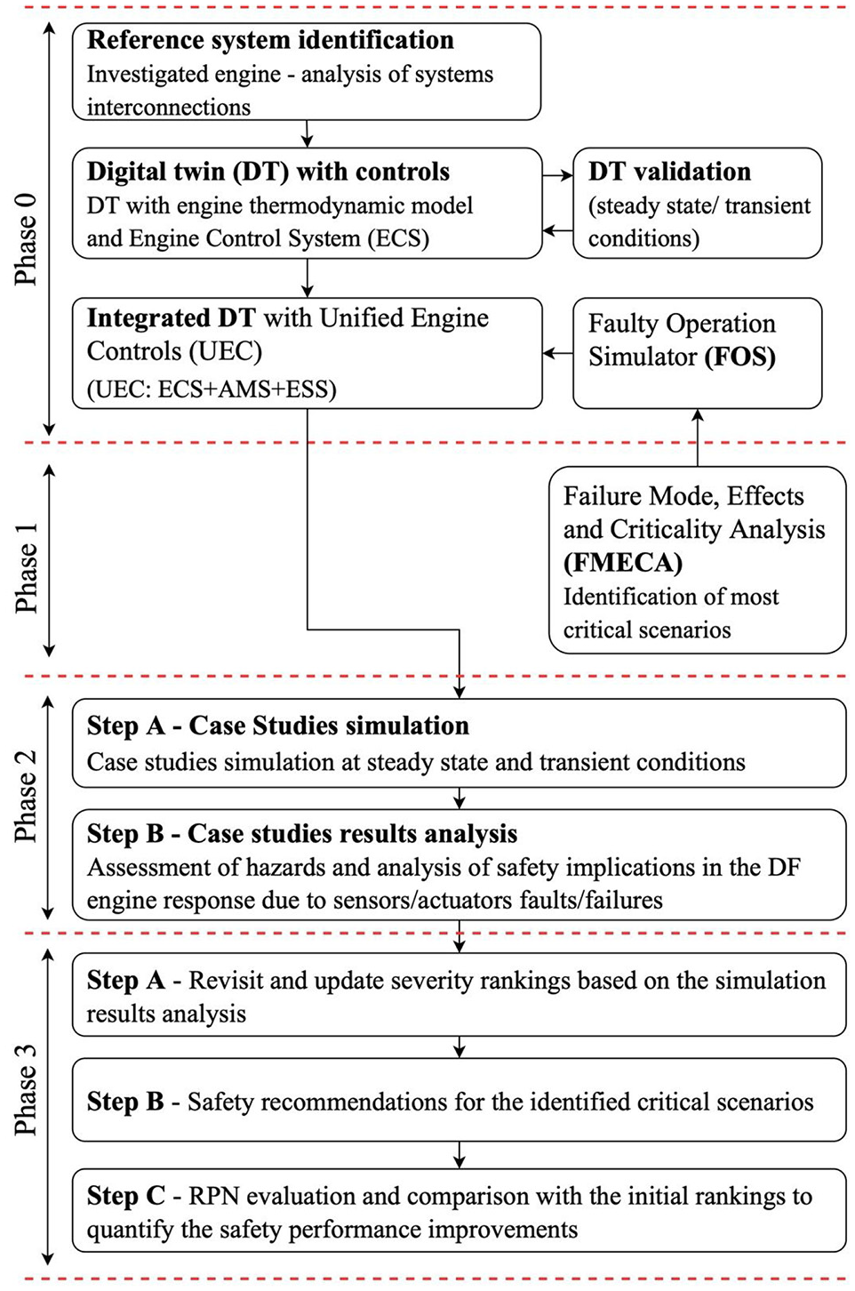
Methodology layout.
Employed systems/models description
Investigated engine
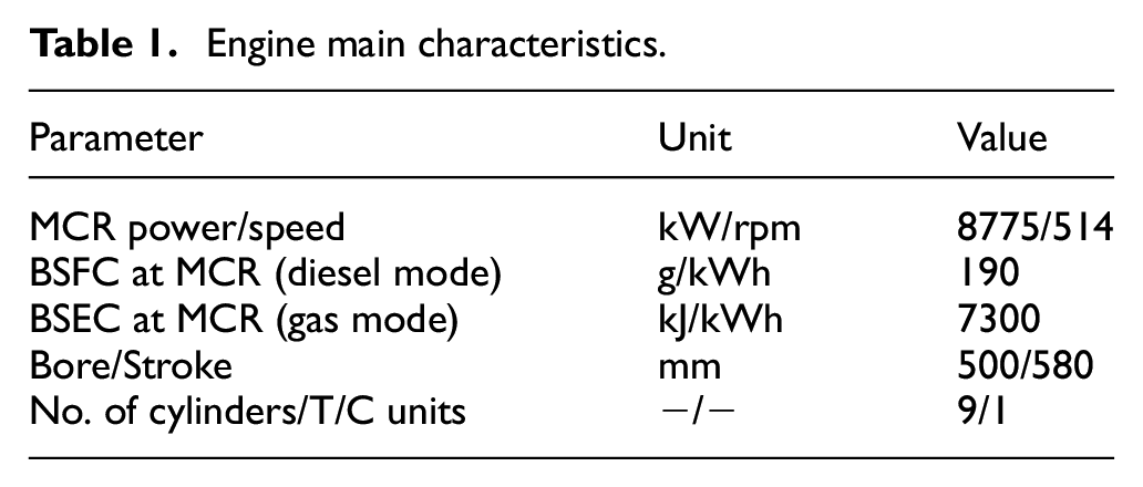
The reference system selected for investigation in the present study is the Wärtsilä 9L50DF. 9 This is a marine four-stroke DF engine, equipped with a turbocharger unit, able to mainly operate in the following modes: gas mode (DF), diesel mode (DI), whilst offering fuel sharing mode as optional. The engine geometrical and operational particulars are reported in the manufacturer product guide 9 whereas the main engine characteristics are illustrated in Table 1.
Engine main characteristics.
Engine digital twin (DT), unified engine controls (UEC) system and FOS
The engine digital twin (DT) employed in this study was realised in the GT-ISE. 56 This software provides the tools, libraries and functionalities to address the inherent complexity of the engine and its control system modelling as well as the interfaces required for the programming of the controller logical functions. In addition, GT-ISE is a tool that has been extensively used in both academia and industry 57 for modelling a considerable variety of engine types, sizes and fuels.
The DT of the Wärtsilä 9L50DF engine (Phase 0) consists of the engine thermodynamic zero/one-dimensional (0D/1D) model representing the main engine, and the Engine Control System (ECS) functional model representing the engine control systems. Both the engine thermodynamic model and the ECS functional control structure and functionalities are reported in previous publications of the authors53,54 and therefore, will not repeated herein. The modelled engine subsystems and components as well as the interactions with the considered control monitoring and safety systems are illustrated in Figure 2.
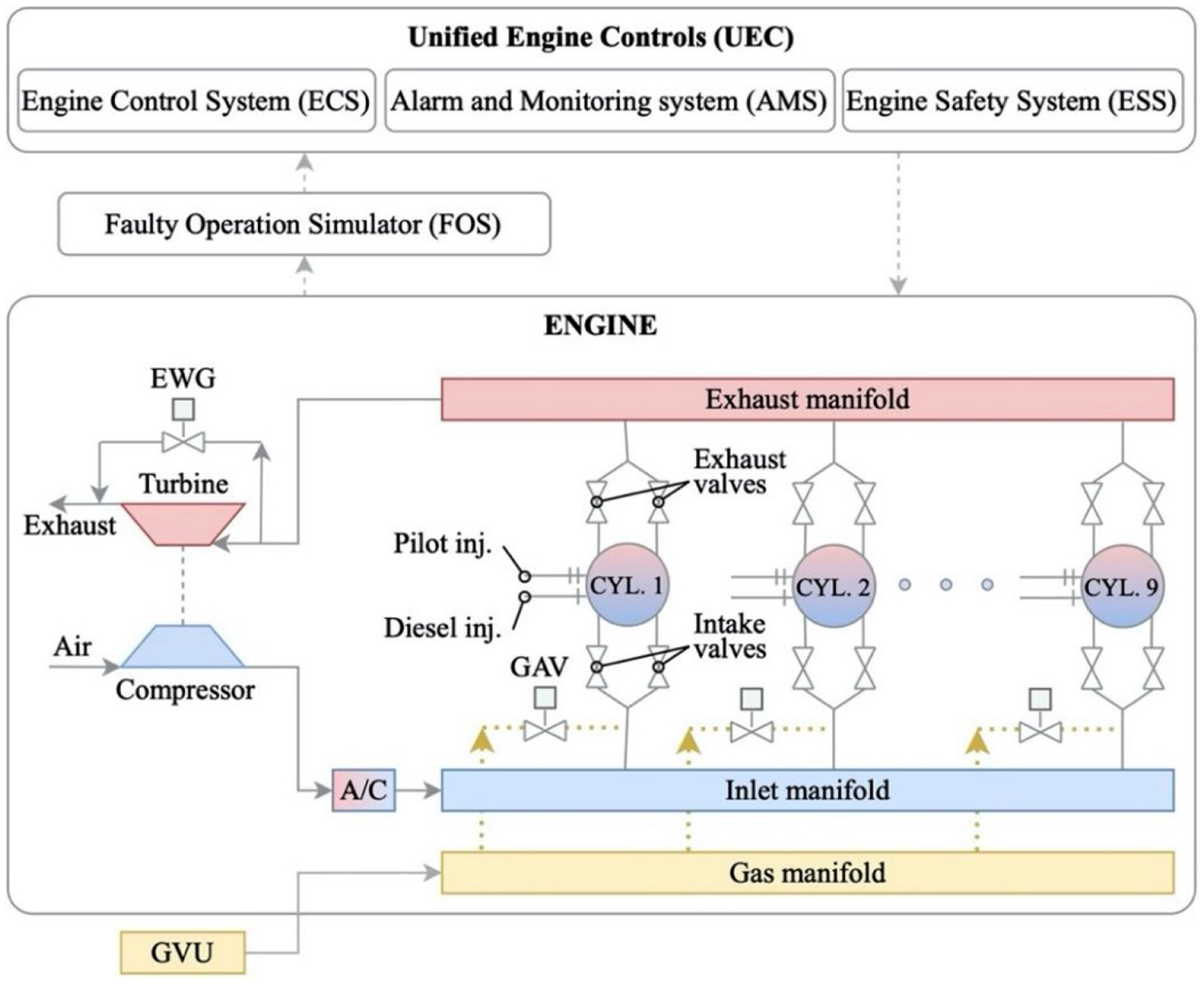
Investigated engine digital twin (DT) and faulty operation simulator (FOS) layout.
The Alarms and Monitoring System (AMS) and the Engine Safety System (ESS), which are grouped and linked with the Engine Control System (ECS) forming the unified engine controls (UEC), primarily exchange safety-critical information for the engine operation, and secondly monitor several engine performance parameters activating appropriate alarms (when the manufacturer’s defined thresholds are surpassed) for avoiding hazardous operational scenarios. The Faulty Operation Simulator (FOS) allows for the investigation of the engine response under critical components (actuators/sensors) faults or failures via simulations. This is achieved by handling actuators and sensors signals, and thus reproducing faulty or failure component conditions, when activated. Component failure rates and faulty operation data (errors) for simulating actuators and sensors faults or failures were either retrieved from the pertinent literature review or were defined based on authors’ experience. It must be noted that the engine sensors and data acquisition system dynamics are not modelled in this study.
Failure mode, effects and criticality analysis (FMECA)
FMECA is a method that is used to identify potential failure modes and to assess the impact of those failures on the system, applicable to different system abstractions and system levels. 58 In this study, the engine control system critical components are identified and ranked based on the frequency, detectability and impact of a potential component malfunction using FMECA employing the worksheet proposed by IEC, 59 with minor amendments.
The failures ranking is carried out based on the Risk Priority Number (RPN), which is calculated as the product of occurrence, severity and detectability according to the following equation:

where O, S and D denote the occurrence, the severity and the detectability of the failure modes, respectively.
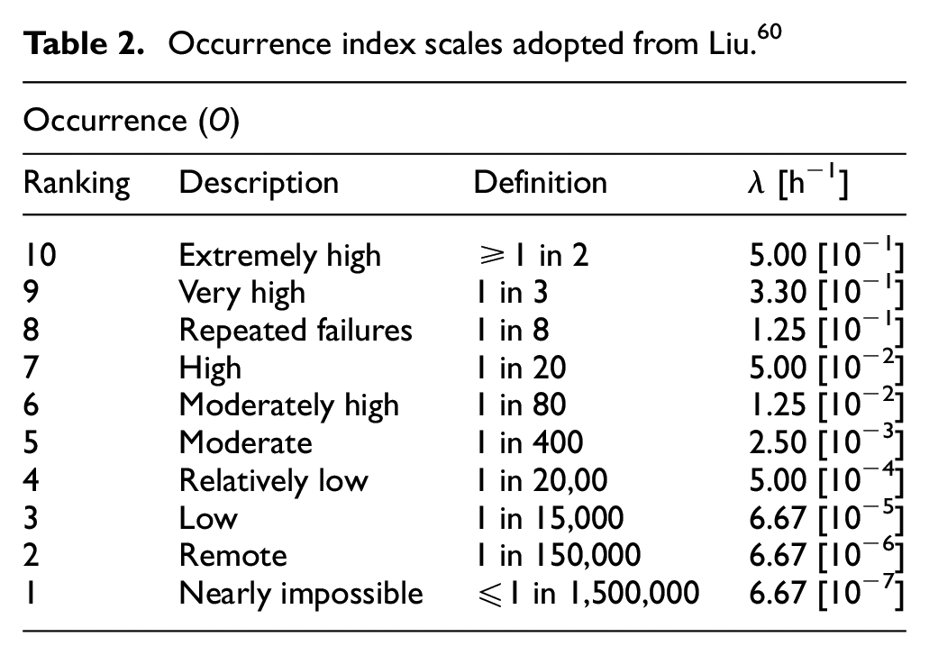
For the ranking of the occurrence, severity and detectability, the tables reported in Liu 60 are used, which are presented in Tables 2 to 4. The frequency ranking is based on the OREDA database complemented by other databases. 61 For estimating the detectability, the engine detectability subsystems/components are considered. For estimating the severity ranking the consideration of potential engine components redundancies along with the authors’ expertise is used. For verifying the FMECA results, safety analysis reports from similar engines are employed. The critical failures are determined using the Pareto 62 80/20 rule, according to which the 20% of the identified failure scenarios are considered as critical and are further investigated by simulation.
Occurrence index scales adopted from Liu. 60
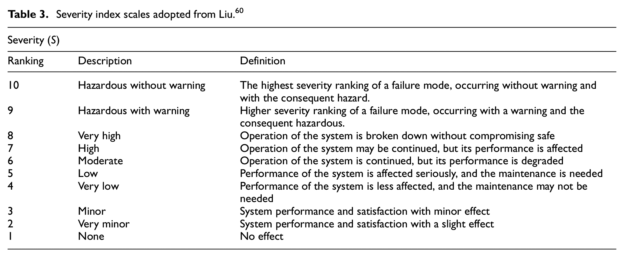
Severity index scales adopted from Liu. 60
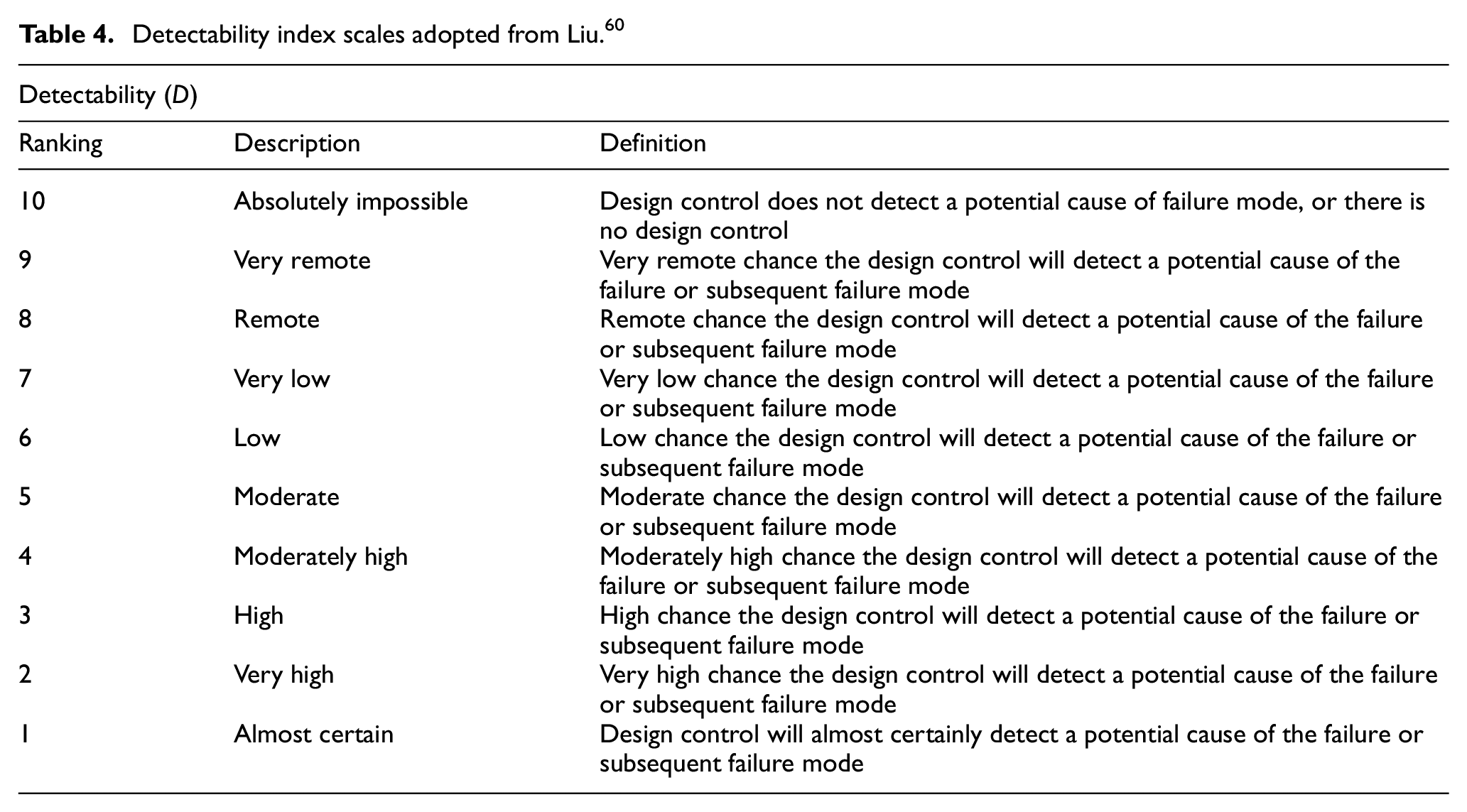
Detectability index scales adopted from Liu. 60
The following engine systems are considered in the FMECA: (a) the pilot injection system; (b) the GAV; (c) the GVU; (d) the diesel fuel system; (e) the EWG valve actuator; (f) the speed sensors for the engine and the turbocharger; (g) the pressure sensors (including boost and gas (fuel) manifold pressure); and (h) the temperature sensors. These systems constitute the main components required to control the combustion process and the switching of the engine operating modes.
For carrying out the FMECA, only the engine response is considered, disregarding any impact on the ship and its systems. It must be noted that the FMECA is based on the assumptions that the engine manufacturer maintenance procedures and intervals are followed, whereas the engine systems are operated and maintained by qualified personnel.
Results and discussion
Phase 0 – engine simulation tool (digital twin) validation/verification
The engine simulation tool was validated for a number of steady state operating points (25%, 50%, 75% and 100% loads) as reported in Stoumpos et al., 54 as well as in transient operation scenarios as presented in Stoumpos et al. 53 and Theotokatos et al. 51 The derived performance and emissions parameters compared with the respective data experimentally obtained from the engine shop tests and the available data published in the pertinent literature. The maximum percentage error identified after the comparison between the measured and the predicted parameters was found below 3.5% and 2.5% for the steady state and the transient operations respectively, thus indicating that the employed simulation tool provides adequate accuracy.
Phase 1 – FMECA results
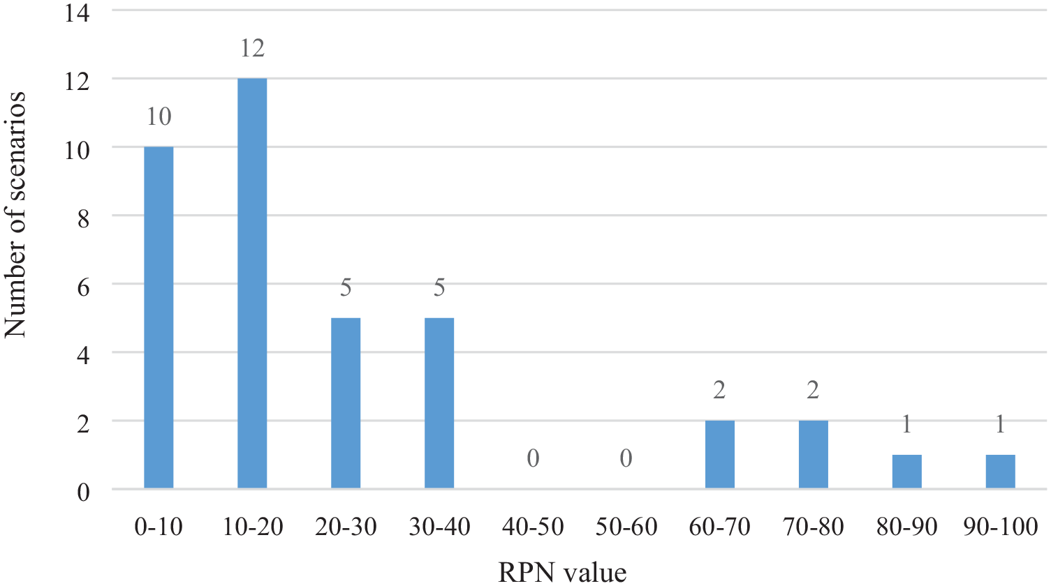
Following the FMECA application, in total 38 hazardous scenarios (case studies) were identified, the distribution of which is provided in Figure 3. It can be inferred that the RPN of the identified scenarios is generally low to moderate, which implies that the engine manufacturer has already taken appropriate risk mitigation measures, such as enhancing the failure detectability of the engine components (actuators/sensors), which reduces the RPN.
Distribution of the identified hazardous scenarios by FMECA.
Using the Pareto 80/20 rule, eight scenarios (case studies) were finally classified as critical (their RPN ranking corresponds to the top 20% scenarios). The description of these scenarios is presented in Table 5. The occurrence for these scenarios was determined using failure data primarily from the OREDA database 61 leading to the rankings in the region of 2 or 3 (low or remote likelihood of occurrence). Less common are the issues occurring due to software and hardware malfunction or failure on the engine ECS, however, their functionality exhibits major impact on the engine operation under faulty conditions and must not be neglected. The severity was determined using the potential consequences of the failures and their impact on the engine. High severity was assigned to scenarios related to the speed and boost pressure sensors as well as the EWG valve, as their faults/failure can lead to serious engine damages. Low severity ranking was assigned to the other scenarios, as they lead to engine degraded performance. The detectability was ranked in the region of 3−4, as the investigated engine already employs several detection systems.
Selected critical scenarios to be further investigated by simulation.
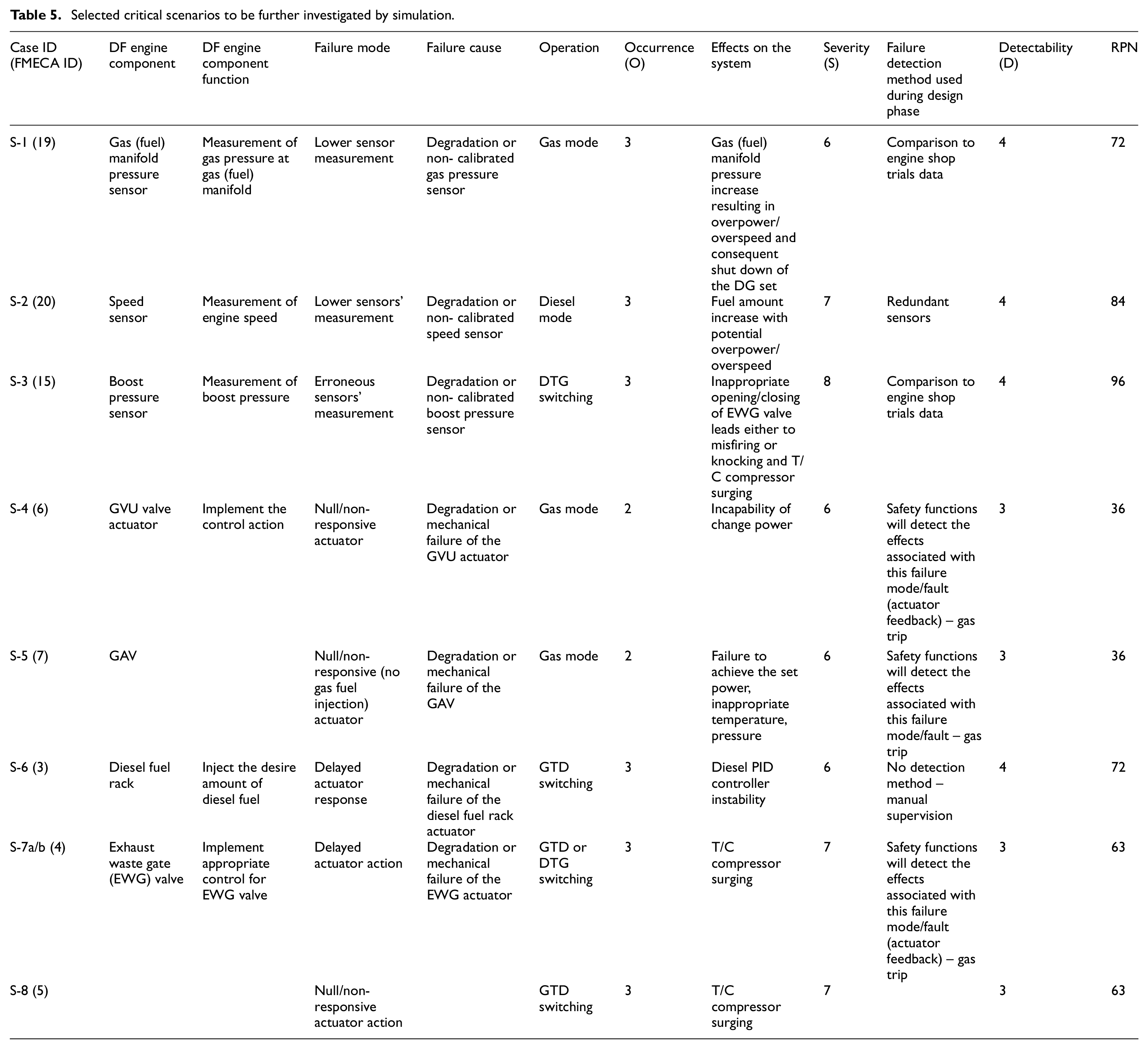
The RPN ranking presented in Table 5 reveals that the faulty engine components identified for the scenarios S-2 and S-3 are categorised as critical due to their high severity index (which denotes that these components considerably affect the engine operation). In this respect, the speed and boost pressure sensors are vital engine components, due to their impact on the engine control; potential faults occurring on these components will considerably affect the engine response. Other critical failures (exhibiting the highest RPN values) are interconnected to the EWG and GVU valves’ actuators, the diesel fuel rack actuators, the GAV and the pilot fuel injector.
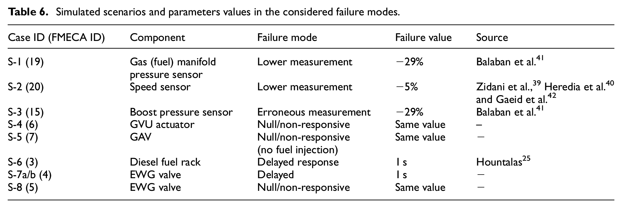
For these selected scenarios (case studies), simulation runs were carried out to identify the engine and its components response at faulty conditions. The list of simulation runs (case studies) along with the considered failure modes ad the affected parameters values are provided in Table 6. As the EWG valve and its control was found critical for the engine response, the case studies S-7a and S-7b are simulated to further investigate the potential engine safety implications. These case studies (S-7a and S-7b) are investigated for both the gas to diesel (GTD) and diesel to gas (DTG) modes switching. The simulation case studies S-1 to S-8 are performed for transient conditions, which are considered more risky, where the engine initially operates under the normal/healthy state and for a given time the sensor/actuator demonstrates a faulty response. The alarm limits for several engine performance parameters are taken into account to identify responses that lead to potential safety implications for the engine.
Simulated scenarios and parameters values in the considered failure modes.
Phase 2 – critical failure scenarios simulation results
The findings drawn from the analysis of the derived simulation results of the cases studies S-1 to S-8 are presented in Table 7. As shown in Table 7, the ECS response as well as the faults effects on the engine response are identified, whereas the potential safety implications, which were derived by taking into account the engine manufacturer design and alarm limits are reported for all case studies. Summarising the findings of Table 7, the faults related to the gas (fuel) manifold pressure sensor at the gas mode operation (case study S-1) may be associated with potential misfiring issues due to the lambda values exceeding 2.4 as well as the exhaust gas temperature surpassing the alarm limits by 2.3% for approximately 1 s. It must be noted that the gas fuel PID controller is able to identify discrepancies in the gas (fuel) manifold pressure via the speed sensor feedback and counterbalance this safety implication by reducing the GAV injection duration.
Simulated case studies and summary of the derived results.
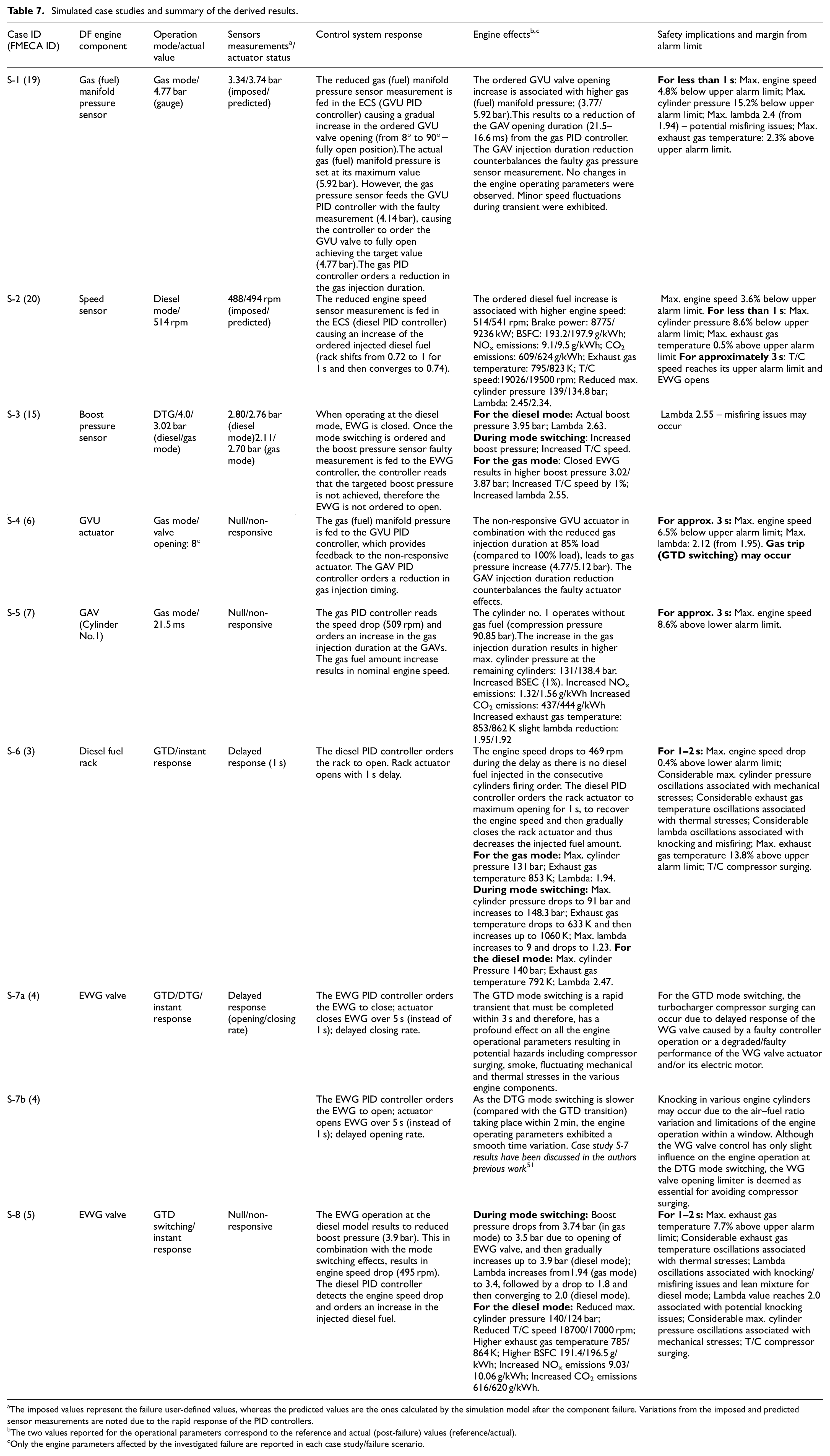
The imposed values represent the failure user-defined values, whereas the predicted values are the ones calculated by the simulation model after the component failure. Variations from the imposed and predicted sensor measurements are noted due to the rapid response of the PID controllers.
The two values reported for the operational parameters correspond to the reference and actual (post-failure) values (reference/actual).
Only the engine parameters affected by the investigated failure are reported in each case study/failure scenario.
For the case study S-2, the speed sensor faulty operation at the diesel mode seems to have a major effect on the T/C speed, in the case of engine over-fuelling; the T/C speed exceeds its alarm limit by 4.3% for 1 s, whereas the exhaust gas temperature exceeds its alarm limit by 0.5% for 3 s. Special consideration should be given on the fact that the speed sensor has a direct and critical impact on the diesel fuel PID controller, thus, to the diesel governor and the delivered diesel fuel amount into the engine cylinders.
For the case study S-3, a boost sensor fault is investigated under DTG modes switching, causing increased boost pressure and T/C speed due to the fault impact on the EWG valve controls. The lambda values recorded are relatively higher than expected after the mode switching (in the gas mode), which may lead to potential misfiring issues. Therefore, it can be inferred that the boost sensor related faults are critical for the engine operation due to their considerable impact on the EWG controller (especially in the gas mode), and consequently to the engine response.
Furthermore, the engine response captured in the case studies S-4 and S-5 is found within the set alarm limits, where the gas controller countermeasures for the introduced faults in each case (GVU valve actuator and GAV, respectively); switching to the diesel mode may occur in the former case. On the contrary, the diesel rack and EWG valve faults introduced in the case studies S-6 and S-8, respectively under the GTD mode switching, demonstrate that the engine response can be greatly affected. Specifically, for the case study S-6, the speed reaches its lower limit for a period of 1−2 s, the exhaust gas temperature exceeds the alarm limits by 13% and the T/C compressor surging occurs. In addition, considerable oscillations are observed for the maximum cylinder pressure, exhaust gas temperature and lambda, which may be associated with mechanical and thermal stresses as well as knocking/misfiring issues. Case study S-7 exhibits similar engine response to S-6, with the exhaust gas temperature exceeding its alarm limits by 7.4%. Hence, it can be concluded from case studies S-6 and S-7 that the diesel rack and the EWG valve along with their controllers are of crucial importance for the engine smooth operation. Potential faults in these components or their control and feedback sensors can have severe impact on the engine response with considerable safety implications. Lastly, with regards to the case studies S-7a and S-7b, the key findings are discussed in detail in authors previous work. 51
Phase 3 – ranking update and safety recommendations
The findings from the simulation results analysis were used to update the severity rankings for the critical scenarios, which have been initially determined based on the authors’ expertise and previous FMECA studies. For instance, for the scenario S-1, considering the gas fuel PID controller ability to counterbalance the gas fuel manifold pressure sensor failure, the severity could be reassessed to 5. Similar conclusions can be made for the scenarios S-4 and S-5, where lower severity can be assigned. Based on the findings from the simulations results, the severity ranking for the scenarios S-2, S-3, S-7 and S-8 remained the same with their initial estimations. For the scenario S-6, the severity ranking was increased to 7 (from the initial 6) to reflect the significant engine speed reduction and considerable increase of the exhaust gas temperature. The reassessed severity is depicted in Table 8. Based on the preceding discussion, it is deduced that the simulation results analysis verified and updated the severity rankings, which were initially estimated based on the authors’ experience and the pertinent literature.
RPN percentage reduction.
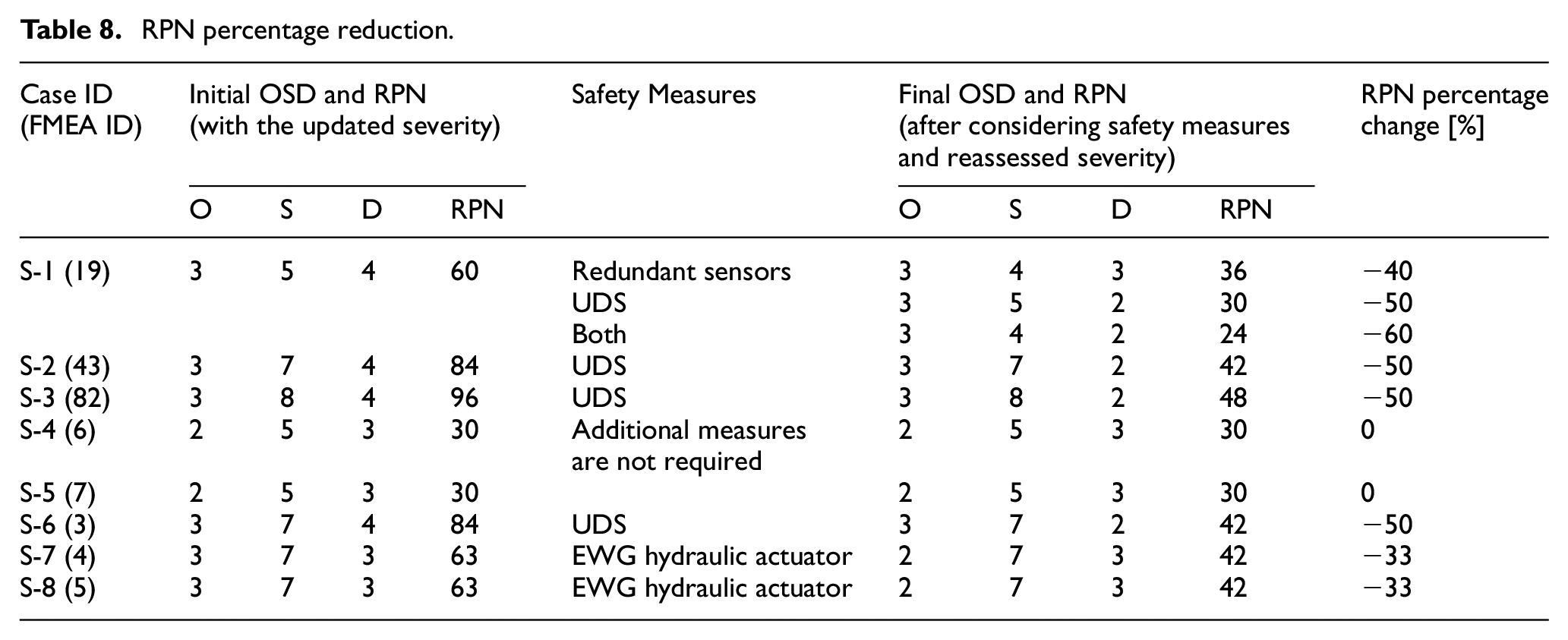
To reduce the RPN for the investigated scenarios, the risk reduction measures presented in Table 8 are recommended. In specific, for the scenario S-1, redundant sensors and/or intelligent health monitoring systems with corrective actions capabilities (such as UDS 55 ) may be employed to improve the detectability and reduce the scenario severity. These risk reduction measures are expected to provide an additional layer for the gas (fuel) pressure evaluation, when the ESS compares these measurements against the pre-set values recorded from the engine shop-trials. Similarly, the scenarios S-2 and S-3 can benefit from an intelligent health monitoring system (e.g. UDS) in terms of detectability, as any faulty (biassed) measurements can more confidently and accurately be detected. It must be noted that for the scenarios S-2 and S-3, redundant sensors are commonly used. Nevertheless, based on the authors’ experience double sensor failures have still been exhibited (in rare occurrence), where the associated impact on the engine operation is high. Moreover, despite the fact that the scenario S-1 and S-3 demonstrate similar sensor faults, these are assessed differently due to the ability of the engine to perform gas trip (GTD fuel mode switching) when the gas (fuel) pressure sensor fails (S-1; as well as the fact that the gas PID controller counterbalances the faulty gas pressure measurement as previously discussed), whereas the boost pressure sensor is used in both diesel and gas modes. Hence, there is no alternative action to reduce the fault/failure impact on the engine operation (as reflected by the higher severity in S-3 compared to S-1).
Scenarios S-4 and S-5 demonstrate low RPN, therefore it was deemed that no additional measures are required. For the scenario S-6, the diesel fuel rack position is commonly verified by manual supervision. This can be directly improved by using intelligent health monitoring systems that employ Machine Learning (ML) tools that apply corrective actions to faulty sensor signals and demonstrate prognostics capabilities to accurately predict potential component failures. For the scenarios S-7 and S-8, the recommended risk reduction measures are fundamentally interconnected with the rapid EWG response required (as the simulation results revealed), as well as the actuator reliability, which can be primarily achieved by the replacement of electric actuators with hydraulic actuators, which are proven to be more reliable and are expected to reduce the occurrence of the EWG actuator failures. Lastly, regular components maintenance/inspection and sensors calibration are envisaged as primary risk reduction measures for all the investigated scenarios, in accordance with the specified intervals by engine manufacturer recommendations.
Discussion
An objective of the safety analysis is to provide safety recommendations. Virtual simulation platforms can assist the safety engineer and the designer of the investigated engine to identify the consequences in cases of failure scenarios and to quantify operational parameters responses by comparing with the upper and lower alarm limits. The safety analysis will also be benefitted through the verification of the FMECA results based on state-of-the-art simulation tools. Thus, Severity and Detectability can be more effectively assessed to reflect of the realistic conditions expected in each identified critical scenario.
In addition, safety recommendations can be more sophisticated and case specific. In principle, the safety recommendations are interconnected with measures to decrease the Occurrence, Detectability and/or Severity (where applicable), and thus the RPN. The latest developments on materials, advanced design algorithms and novel artificial intelligence and ML systems pave the way towards the implementation of new methods for reducing RPN, either individually or in combination with existing methods. For example, Occurrence of a failure (e.g. pilot fuel injector) can be reduced by introducing new and improved materials and design optimisation. Severity of a failure scenario may be reduced by slowing down the engine, or using redundant components, therefore reducing the potential impact. Therefore, it is apparent that the improvement of the Occurrence and Severity rankings are associated with very specific methods. On the contrary, detectability may be improved by either focussing on redundancy of components to ascertain the measurements (or generally signal) trustworthiness or by introducing intelligent systems for the engine and its components health assessment such as the unified diagnostic system (UDS) described in Stoumpos and Theotokatos. 55
Conclusions
This study proposed the use of a simulation tool of high fidelity to complement the safety assessment process for marine dual fuel engines considering the expected operating conditions and taking into account sensors abnormalities and sensors’/actuators’ degradation. By conducting an FMECA, the engine operation hazardous scenarios were identified, whereas their risk priority number was quantified by ranking their occurrence, severity and detectability. Subsequently, the critical scenarios were identified and further investigated by simulation. The analysis of the simulation results allowed for revisiting and updating the severity of the identified critical scenarios, thus their more accurate RPN ranking. For each critical scenario, appropriate measures were recommended and the RPN was re-evaluated and compared with the updated RPN, allowing for the quantification of the safety improvement.
The main findings of the study are the following:
The identified critical hazardous scenarios included faults related with the speed sensor (S-2), the boost pressure sensor and the diesel fuel rack. The main reason these are deemed critical is due to their fundamental contribution and effect to the ECS controllers and consequently to the controlling actions to the engine.
The FMECA results highlighted the importance of the boost pressure and speed sensors failures as well as diesel fuel rack failure, especially during the fuel transient operating modes, where rapid and extreme fluctuations in lambda values are noted, and engine alarm limits are exceeded.
The EWG valve actuator failure was found to be critical due to the impact of the valve response time on the engine operation and the T/C compressor surging effect.
The GVU and GAV (scenarios S-4 and S-5) were found to be of moderate risk; ECS counterbalance failure effects and gas trip can be applied.
The engine operation in the identified hazardous scenarios can suffer from mechanical and thermal stresses, knocking or misfiring occurrence, T/C compressor surge effect and overspeed.
The simulation results analysis supported the quantification of the engine operating parameters variation in the investigated operating scenarios, and thus, the more accurate ranking of their severity.
The simulation results analysis verified the initial rankings for the severity of the critical scenarios, as only slight variation of the initially provided severity ranking took place. Hence, simulation effectively supported the verification of the FMECA results.
The recommended measures included the use of intelligent diagnostics and prognostics, alternative technologies for the fast and accurate actuation of the fuels rack, sensors redundancy as well as hardware upgrades (such as hydraulic actuators) to improve the engine components response time and reliability.
The recommended measures achieved a reduction of the critical scenarios RPN in the range 33%−60%, thus contributed to the substantial enhancement of the engine safety.
This study demonstrated the engine safety assessment process can directly be benefitted from the use of simulation tools. The results from simulation studies function as an additional knowledge source, supporting the quantification of the consequences from the engine operation and hence, facilitate the update of the corresponding severity rankings. In this respect, the simulation results can be employed to complement the experiential knowledge used in the safety assessment process, thus resulting in more confident safety analysis results. The proposed methodology is applicable to other marine engine types. Taking into account the immense pressure of the shipping industry to operate with a net-zero safety profile, this study supports the pertinent decision-making processes, as the safety measures can be evaluated during the design phase and the simulation tools are expected to provide additional insights to the safety engineers. Considering that engine diagnostic tools based on Machine Learning) have continuously been developed, their adoption in the short-term by the engine manufacturers is expected for the identification the engine systems/components faults. In such cases, the methodology presented in this study can constitute a useful safety assessment tool not only for failure modes detection, but also for components faulty operational scenarios identification.
The limitations of this study are as follows. The ‘semi-predictive’ combustion model was selected for modelling the combustion process of the investigated engine. Therefore, failures related to the pilot injector cannot be accurately simulated. The developed engine thermodynamic model does not accommodate engine knocking and/or misfiring prediction, whereas the engine knocking and misfiring detection controls are not included in the Engine Control System (ECS) model. The OREDA database, which is used in offshore installations, has supported the rankings of the investigated marine DF engine. Recommendations for future research studies include the use of other safety techniques and integration with machine learning tools for the safety analysis of marine engine as well as the development of the recommended risk reduction measures and testing in a virtual environment their effectiveness.
Footnotes
Appendix
Acknowledgements
The authors greatly acknowledge the funding from DNV AS and RCCL for the MSRC establishment and operation. The opinions expressed herein are those of the authors and should not be construed to reflect the views of DNV AS and RCCL. Gamma Technologies support is also greatly acknowledged by the authors.
Author Contributions
Conceptualisation, S.S., V.B. and G.T.; methodology, S.S., V.B. and G.T.; software, S.S.; validation, S.S. and G.T.; formal analysis, S.S., V.B. and G.T.; writing – original draft preparation, S.S., V.B. and G.T.; writing – review and editing, S.S., V.B., G.T. and E.B.; visualisation, S.S. and V.B.; supervision, G.T. and E.B.; project administration, G.T. All authors have read and agreed to the published version of the manuscript.
Declaration of conflicting interests
The author(s) declared no potential conflicts of interest with respect to the research, authorship, and/or publication of this article.
Funding
The author(s) received no financial support for the research, authorship, and/or publication of this article.