
Abstract
Digital Twin has become a frontier research topic in recent years and the important development direction of intelligent manufacturing. For numerical control machining, a Digital Twin system can be used as an intelligent monitoring and analysis center by reflecting the real machining process in a virtual environment. The machining simulation is the key technology to realize this kind of application. However, existing machining simulation systems are designed for off-line situation that cannot be used directly in Digital Twin environment. The challenges for machining simulation are analyzed and explained in this article: (1) complete process data representation in simulation system; (2) executing in cooperating with computer numerical control system; (3) more efficient simulation algorithm. In order to meet these challenges, a new machining simulation system is proposed. STEP-NC standard is used to save complete process data exported from the computer-aided manufacturing system and synchronization algorithm is developed based on the communication data of computer numerical control system. Most importantly, an optimized tri-dexel-based machining simulation algorithm is developed to perform high efficiency that can follow the real machining process. Finally, a Digital Twin system for NC machining is presented that has been tested and verified in a workshop located in COMAC (Commercial Aircraft Corporation of China Ltd).
Introduction
Digital Twin is an important development direction of intelligent manufacturing.1,2 It sets a new way to utilize virtual simulation environment to reflect the physical world. For intelligent manufacturing, virtual environment proves a powerful tool to build smart platform for real manufacturing equipment. The concept of Digital Twin is also related to big data,3,4 cloud-based manufacturing5,6 and other attractive concepts, which make it having more possibilities. 7 Digital Twin was first prosed by Professor Grieves in 2003 and it becomes a frontier research topic from 2014. Digital Twin has been discussed and applied by many scholars in multi-domains including manufacturing, energy, design, assembly, and equipment monitoring. In the foreseeable future, the development of Digital Twin is more extensive.
Many research works have been proposed to show the possibilities of Digital Twin in manufacturing. Tao presented a comprehensive review about the State-of-the-Art for Digital Twin in industry. 1 Yun et al. 8 proposed a data-centric middleware to build a Digital Twin Platform used in distributed multi-systems in automobile manufacturing and an example is shown about the development of car advanced driver-assistance system (ADAS). In Moreno et al.’s 9 research, a virtual simulation environment reflecting a sheet metal punching machine is presented and the way to construct Digital Twin system is summarized as five steps. In Cai et al.’s 10 research work, a virtual machine tool is constructed by fusing the sensor data and the surface roughness is evaluated. Digital Twin is also applied to improve the intelligence in manufacturing process control. As discussed in Rosen et al.’s 11 work, a Digital Twin system can replace the function of manufacturing execution system (MES) while an example production line is presented to support this argument. For product design, there are some applications of Digital Twin, such as the research works presented by Fei et al. 12 and Schleich et al. 13
The significant of applying Digital Twin in manufacturing has been discussed adequately in the research works mentioned above. For computer numerical control (CNC) machining, the improvement on intelligence by Digital Twin is to monitor the real machining process in the virtual environment. As a comparison, existing CNC machining process is not intelligent enough. It is similar to a black box: the input to CNC is a NC program and the output is the machined part. There is not sufficient attention paid to the intermediate machining process. It is difficult to obtain accurate geometry and processing schedule of the part being processed. Advanced, the degree of conformity between real machining process and designed process requirements determines the quality of the product. Digital Twin system for CNC machining provides a new mean of monitoring and evaluating the process.
For a typical Digital Twin system, five elements are needed: 14 physical entity, virtual entity, services, Digital Twin data, and connection. Considering the machining process, the data from CNC system or other sensors are timing information such as cutter locations, cutting force, spindle power. States of machined part, cutter, or machine tool cannot be acquired directly from these original data. Therefore, simulation is the key function to reflect the real machining process and this is the main concern of this article. Corresponding to the five elements of Digital Twin, this article focuses on the implementation of virtual entity and Digital Twin data. For virtual entity, a new modeling & simulation method is researched to bridge over the gap between the design process and machining process. For Digital Twin data, the data fusion method is inspected cooperating with the new modeling & simulation and CNC system.
Existing research works on model & simulation method in Digital Twin are valuable for this article. For example, a web server-based Digital Twin modeling structure is proposed by Schroeder et al. 15 Data exchange between heterogeneous systems is also discussed by Schroeder et al., 16 and the automation ML is adopted to achieve this. The important feature of this new model & simulation method is to integrate information from multiple domains. But the specified modeling method of machining process and CNC is not discussed before. Data fusion is a characteristic function in the studies of Digital Twin and has aroused the scholar’s interest. Coronado 5 discussed a reference system architecture for shop floor Digital Twin application and the problems of data fusion in the physical and virtual workshop model are discussed. Cai et al. 10 developed a Digital Twin system for a milling machine in which the monitoring data is classified according to the designed machining process and the surface roughness can be predicted. All these research works contain a common idea that information from product design and process planning is important for Digital Twin to implement data fusion. There are few researches on data fusion through simulation technology.
In this article, machining simulation method is reformed to integrate with CNC in-process data and the real machining process is monitored in virtual simulation system. Dynamic in-process workpiece geometry calculation is the core problem to be resolved in this article. This in-process model can be used to estimate machining status including current working step, tool path being executed, and remaining processing time. In addition, the geometry simulation result is the prerequisite for physical simulation. Physical simulation results, cutting force and material removal rate, are critical data for tool wear evaluation, surface quality evaluation, process planning, and other analysis of the machining process. Executing synchronously with real machining process, this application can be called on-line simulation which is used for monitoring and evaluating the machining process. Therefore, simulation-based Digital Twin system is helpful to improve the intelligence of machining process. Because the research is in its infancy and limited by the length of the article, this article discussed on-line geometry machining simulation implementation and application.
Machining simulation is an essential technology for the Digital Twin system proposed here. However, existing simulation methods are not designed for on-line mode and should be modified. Combining with communication with CNC, a novel machining simulation system is developed. First, data flow from computer-aided manufacturing (CAM) system to simulation is reformed and the STEP-NC standard is used to represent complete process data. Second, a tri-dexel-based simulation method is proposed that Boolean operation and mesh generation algorithms are optimized to be efficient enough for synchronously executing with machine tool communication. This system has been tested and verified in a workshop located in COMAC (Commercial Aircraft Corporation of China Ltd). The test results show that this system is suitable for 3-axis and 5-axis machining. Finally, to show the efficiency of the optimized machining simulation method, statistics of single updating time consumption and test cases are illustrated.
Structure of rest article is listed as following: In the following section, challenges for machining simulation system in Digital Twin environment are discussed. In the next section, a machining simulation system for Digital Twin is presented and optimizing strategies that overcome the limitation of existing simulation method are explained. Cases Studies are presented next, and some experiments are performed in COMAC. In the final section, conclusion and future works are presented.
Challenges for machining simulation system
Machining simulation has been successfully applied in manufacturing for decades. Existing simulation systems are designed to validate the machining process and check error in the off-line situation. However, for on-line situation, the machining simulation system should be reconsidered. In this section, challenges for applying machining simulation in Digital Twin are discussed.
From design to machining, the workflow of traditional machining simulation and Digital twin system are compared. The relationship of simulation system, CNC system, and computer-aided design (CAD)/CAM is illustrated in Figure 1. In traditional off-line situation, the machining simulation is used to validate the tool path before the G-code is sent to CNC for machining and there is no connection between simulation and CNC. CAM system provides the necessary data for simulation, including tool path, workpiece geometry, cutter geometry, and working step information. In Digital Twin environment, machining simulation is a reflection of real machining process and executes synchronously with CNC system. Based on machining simulation, machining status monitoring can be achieved, for example, demonstrating the geometry machined workpiece, identifying the current working step, evaluating remaining processing time. Cutter locations are acquired from CNC system in real time to reflect the real machining process and the tool path from CAM system is used as samples for comparing. It is obvious that machining simulation system for Digital Twin is quite different from the traditional system including input, output, and executing mode.
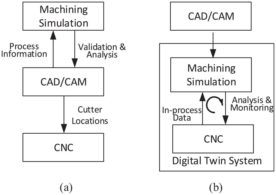
Data flow comparison between traditional off-line simulation (a) and on-line simulation (b) in a Digital Twin system.
The difficulties of applying machining simulation in Digital Twin can be summarized as three points, data integrity, cooperation with CNC system, and efficient machining simulation algorithm. These difficulties are discussed in the following subsections.
Complete process data
Machining simulation in Digital Twin environment needs complete process data to reflect the real machining. Communication data from CNC should be matched with the design data to achieve the data fusion in virtual simulation system. The communication data from CNC are raw and unorganized, such as cutter location, feed rate, and spindle speed, that are unusable in machining simulation. Complete process data from CAM are also necessary to reorganize the communication data. However, in traditional workflow, the data output from CAM is also incomplete. G-code contains only tool path information which is even not enough for off-line machining simulation. Using G-code is also inconvenient to distinguish working step for further analysis. The shapes of tool and workpiece are manually imported or more automatically imported from CAM. 17 The geometry models of tool and workpiece are necessary for Boolean operation in machining simulation and complete process information in CAM is important for data fusion in Digital Twin system. In summary, three types of data are lost in traditional workflow: tool geometry, workpiece geometry, and complete process information.
Cooperation with CNC
Different from the off-line simulation, the on-line simulation system must execute synchronously with CNC in Digital Twin to monitor real machining status. In this mode, cutter locations are acquired from CNC in each update cycle and Boolean operation is performed every time. So the count of cutter locations from CNC is much more than G-code. The comparison between these two cases is illustrated in Figure 2. And some commonly used optimization methods are not available. In off-line simulation (Figure 2(a)), the envelope volume of tool is built for two adjacent cutter locations to skip the intermediate feeding process. Because a large proportion of the tool path is plain line (straight line, arc line), the cutter envelope volume helps to reduce the number of Boolean calculation. However, in on-line simulation (Figure 2(b)), the cutter locations are obtained from CNC and the amount of points increases greatly. For each cutter location, Boolean operation is performed and the visualization is updated that consume a lot of computing resource.
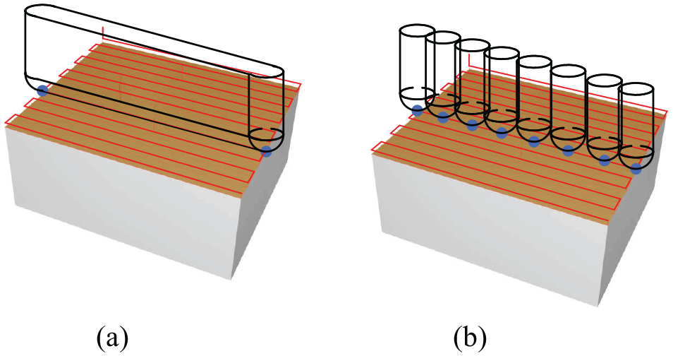
A dramatic increase in the number of cutter locations. (a) Off-line simulation: only one cutter envelope volume is generated between two adjacent cutter locations. (b) On-line simulation: Boolean calculations are performed for every cutter location from CNC system.
For machining process monitoring, the current working step must be identified by virtual machining system from a set of adjacent cutter locations from CNC system. Identifying the right working step is an important function, because this is the basis of executing machining simulation synchronously. On one hand, tool geometry is determined by the current working step and this information is passed into simulation system to cut the workpiece with right tool shape. On the other hand, finding right working step makes the process analysis more purposeful because process requirements are different for different working step. In addition, analysis results are organized into working step struct that can be traced by CAM system to improve processing technology.
More efficient machining simulation
To meet the challenges mentioned above, high efficient machining simulation is necessary. In this section, the efficiency of existing simulation methods is compared. This article concentrates on geometry machining simulation which is the fundamental function for Digital Twin. Physical simulation is also essential for machining status estimating:18,19 cutting force, surface quality, and tool wear. Credible physical simulation depends heavily on efficient and accurate geometry simulation. 20
Various geometry simulation methods have been researched during the last decades. Existing geometry machining simulation methods mainly fall into three categories: 21 solid-based, object space-based, and image space-based. The most accurate simulating result with the highest fidelity can be achieved by the solid-based method, 21 which requires CSG or B-rep model for analytical intersection.22,23 Boolean operation in solid-based method takes a lot of calculation time as the geometry becomes complex. Hence, this method is rarely used for fast tool path verification. 7 In industrial application, object space-based method (Octree, 24 Z-map, 25 etc.) and image space-based method (Z-buffer, Tri-dexel, etc.) 17 are frequently used. Ideas of these two methods are the same: workpiece geometry is subdivided into simple elements with limited amount to balance accuracy and space complexity.7,21 Compared with the image space-based method, object space-based method consumes much more memory, because over-fine subdivision can generate dramatic numbers of elements. 26 Moreover, the triangle mesh generation in object space-based method is also time-consuming.27–29 The comparison result is listed in Table 1. Image space-based method maintains a better balance between efficiency and accuracy.
An intuitive evaluation of machining simulation algorithms, including efficiency, accuracy and interactivity.
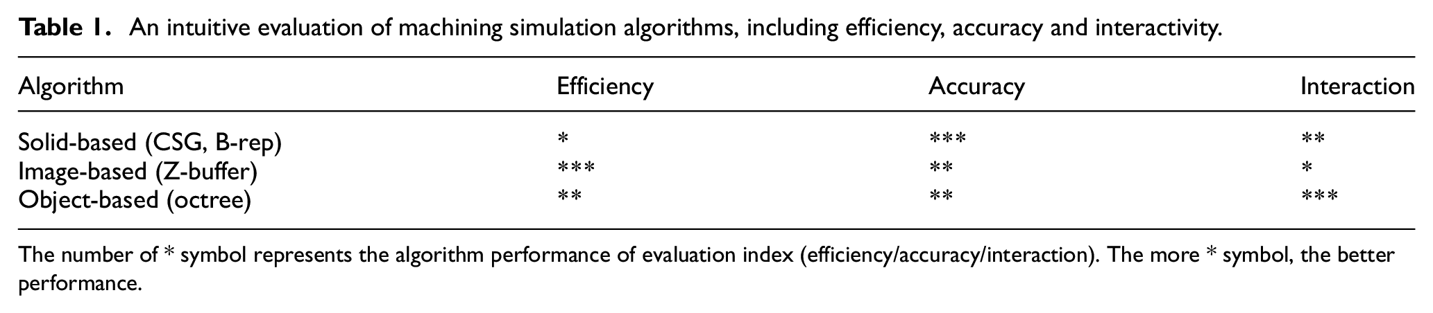
The number of * symbol represents the algorithm performance of evaluation index (efficiency/accuracy/interaction). The more * symbol, the better performance.
A machining simulation system for Digital Twin
To handle the challenges listed in previous section, a specified and optimized machining simulation system is proposed. This system can be app applied in Digital Twin environment cooperating with real CNC machine tool. The traditional simulation system is reformed in three aspects. First, STEP-NC standard is used to represent the complete process data from CAM system. Second, communication with CNC system is achieved by using MTConnect and OPC unified architecture (OPC-UA). The communication data are matched with STEP-NC data in every updating step to provide a stable on-line monitoring for machining simulation. Third, the optimized tri-dexel-based simulation method is developed to reduce the computing resource consumption as far as possible to follow the real CNC machining process.
The structure of this Digital Twin system is illustrated in the Figure 3. There are three modules in this system: STEP-NC process data, on-line simulation, and cooperation with CNC. On-line simulation algorithm is the key module to this system. STEP-NC file provides static theoretical process information and cooperation with CNC provides dynamically revised processing information. Machining status monitoring is the objective of this system which is an indispensable function for intelligent CNC machining.
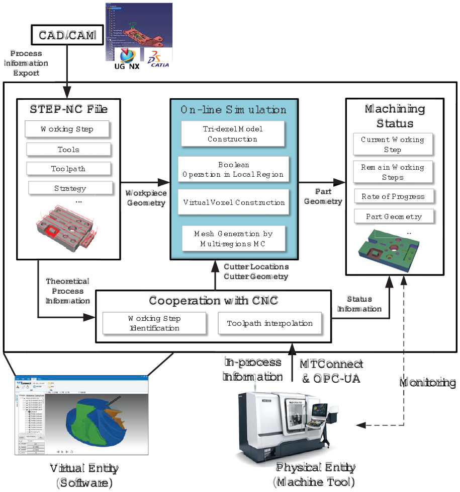
The structure of the Digital Twin system for machining.
Complete process data in STEP-NC
As discussed in previous section, Digital Twin system for machining needs a complete process data model to reflect the real machining process. In traditional machining simulation system, G-code is adopted to describe the machining process for decades. However, G-code file only contains low-level data and some process information is lost when output from the CAM system. To solve this problem, STEP-NC standard is applied to replace G-code. STEP-NC is intended to be the next generation information exchange standard for NC machining. Compared with G-code, STEP-NC standard provides more possibilities to represent process information. Because of this advantage, STEP-NC standard can also be used as an intermediate format between software in manufacturing. 30
CAM system is the source of process information in the field of numerical control machining. Process information in CAM system includes working step, geometry of workpiece, geometry of tool shape, and tool path. All these information can be mapped into STEP-NCs data structure as listed in Figure 4. By applying secondary development technology, process information in CAM system is exported automatically and written into a single STEP-NC file. In virtual simulation system, STEP-NC file is parsed and the process information is organized as an internal data structure.
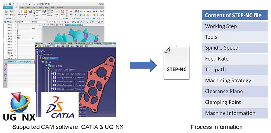
The complete process information from CAM system is stored in a STEP-NC file.
The STEP-NC-based data model is applied in various modules of the Digital Twin system. On one hand, simulation system reads STEP-NC file as input and the complete process data can be accessed. On the other hand, communication data from CNC system are matched to the STEP-NC data structure to achieve data fusion.
Connect with CNC
To access the machining status in virtual environment, the simulation system is connected with the CNC system. For modern CNC system, it becomes more and more open for data acquisition and connecting with other equipment to achieve intelligent functions. OPC-UA is a general machine tool communication technology and has been widely supported. It allows other devices to interconnect with the CNC system via a network cable and the data are obtained in the form of network message. OPC-UA simplifies the way to communicate with machine tool and has strong expandability. In this Digital Twin system, OPC-UA is combined with MTConnect communication protocol to achieve connection with CNC.
MTConnect is a structured machine tool information expression and use a XML structure to hold information. It is not difficult to transmit the MTConnect XML over the network. For this Digital Twin system, the most obvious advantage of MTConnect is the structured data representation of a machine tool that can be corresponded with the STEP-NC data structure. So, OPC-UA and MTConnect are combined that supports the connection between virtual simulation system and CNC system.
However, data from CNC system cannot be used directly in machining simulation. In-process data from CNC system mainly contain primitive information such as cutter locations and feed rate. Therefore, communication data must be traced to find the right working step in virtual machining system. The proposed tracking method contains two parts: first one is to trace the current working step and tool path; second one is the interpolation between adjacent cutter locations.
The tracking process can be described as a neat question: given a collection of chronological points, how to find the corresponding part in theoretical tool path. This can be classified as a searching problem. In this article, the k-d tree searching method is applied to solve this problem. This method is able to find the nearest point from the tool path points efficiently.
With the influence of sampling frequency, the middle points on the tool path between two adjacent cutter locations may be lost. As show in Figure 5, this phenomenon modifies the geometry of tool path used in machining simulation and further influences the geometry of virtual workpiece. This problem is unique in the on-line situation, that is not found in an off-line simulation system. In off-line simulation, the tool path in G-code is interpolated to drive tool movement. In the same way, lost points in Digital Twin machining system can also be repaired by interpolation. And this function is developed based on the ability to trace the right part of the theoretical tool path.
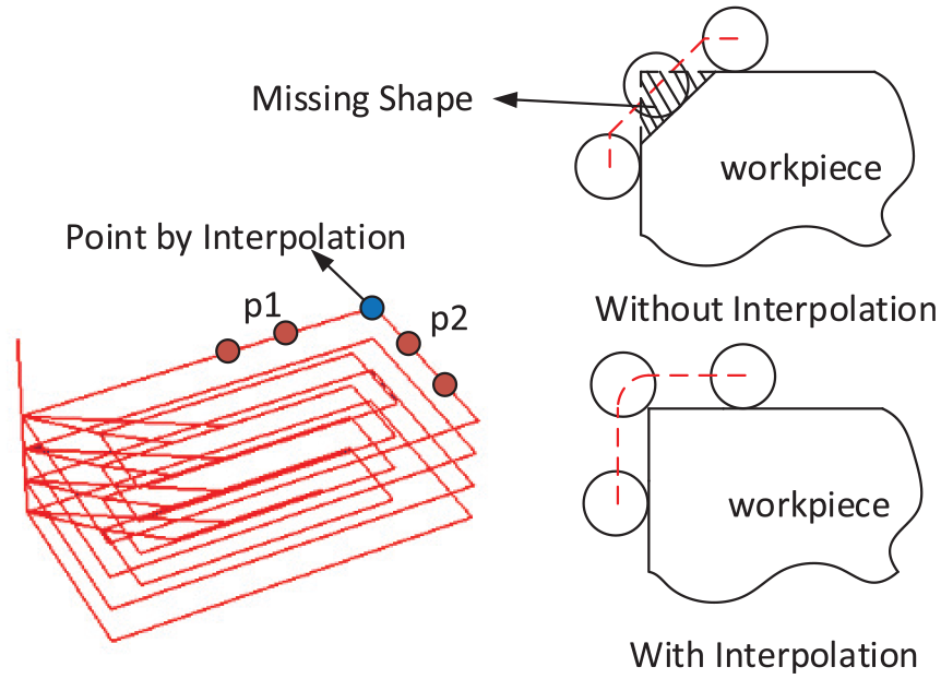
The phenomenon of missing cutter locations during CNC monitoring.
Time step of communication updating is an important indicator that determines the degree of synchronization of virtual machining simulation. Small time step limits the machining simulation to have enough time for Boolean calculation and visualization model updating. However, too frequent communication updating will burden the CNC system and influences the normal CNC control.
As the OPC-UA is applied in CNC connection, the time step is determined by the provider of machine tools. In current state of technological development, the time step of OPC-UA is 100 ms and some advanced CNC machine can update in 50 ms. This means that, within 100 ms, all the simulation-related calculation should be able to finish execution including tool path tracking, cutter locations interpolation, Boolean operation, and visualization model updating.
Optimized tri-dexel simulation method
As discussed in previous section, the increased number of cutter locations and communication updating time step limit the available computing time of machining simulation. To meet these requirements, an optimized tri-dexel-based machining simulation method is proposed. As explained particularly in this section, optimization strategies are designed to improve the efficiency of Boolean operation and mesh generation.
Tri-dexel is a modeling method for discrete representation of workpiece geometry. This method is a combination of multiple z-buffer data structures, which contain three z-buffer along three axis directions keeping orthogonal to each other. There are a lot of research work on tri-dexel-based machining simulation methods.31–33 Tri-dexel-based simulation method combines the advantages of both octree-based method and z-buffer-based method. Compared with octree-based method, this data structure requires smaller memory and performs more efficiently. 29 Compared with z-buffer model, the tri-dexel model is more suitable for applying mesh generation method to create fidelity visualization effect.
There are three steps in the typical tri-dexel-based simulation method. First is to initialize dexel models from the workpiece geometry and tool geometry. Second, Boolean operation is performed between the workpiece dexel model and tool geometry. Third, visualization mesh model of workpiece is generated from tri-dexel model. The last two steps are performed repeatedly for every cutter location acquired from CNC system. A typical tri-dexel modeling process is illustrated in Figure 6. Due to the large amount of dexels, these two steps are time-consuming operation. And optimizing strategies are proposed based on the independence of dexel.
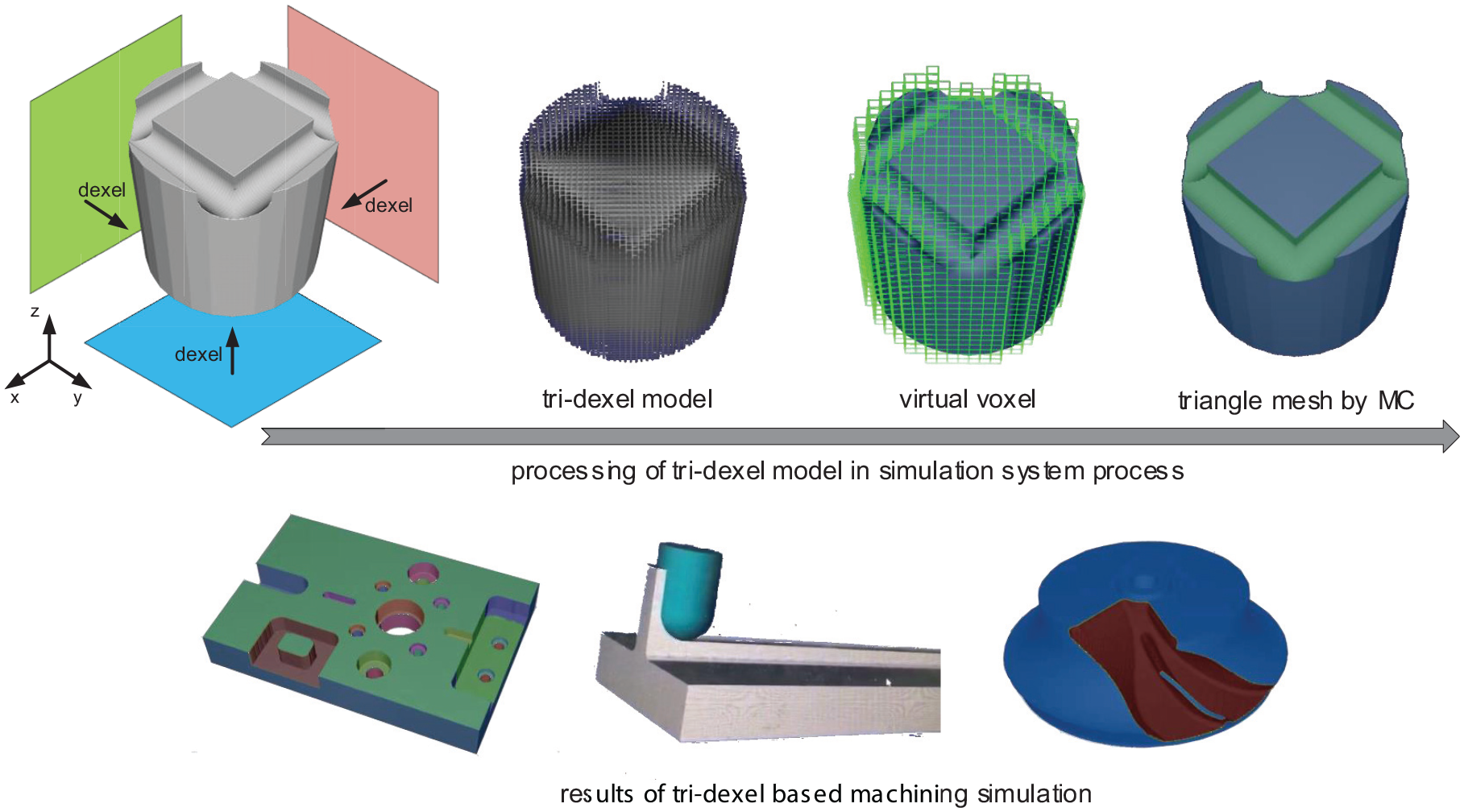
Tri-dexel modeling process and the result of Boolean operation.
To minimize the number of dexels that need to be computed in Boolean operation, the tool bounding box is used to narrow the scope of intersection. First, the dexel model of workpiece is built from the bounding box of workpiece. The dexels are distributed in the three planes and are labeled with an integer index value. These three planes are, x-y plane with index i-j, y-z plane with index j-k, x-z plane with index i-k. The tool bounding box is mapped into the integer index that is represented with three pairs of index value. As shown in Figure 7, the maximum and minimum index value are computed and the Boolean operation is limited into a local region. Inside this region, the dexel model of tool is computed from the theoretical tool geometry expressed with parameter model. Updating dexel model from parameter model of tool is a time-consuming operation especially for the complex geometry shape. Hence, this local updating strategy greatly reduces dexel amount and saves computing resource

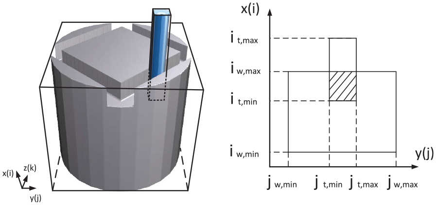
Bounding box of tool is used to perform Boolean operation in local region.
Visualization model generation is a challenging task for z-buffer model which has been researched by many scholars. Colored image effect of z-buffer model is researched in the early stage.34,35 Then, triangle mesh model is getting more attention29,31,36 for interactive visualization on graphics processing unit (GPU). In this article, the concept of virtual voxel is proposed to apply machining cubes algorithm for mesh generation. Bounding box of the workpiece can be divided into a set of neatly arranged voxels. The size of one virtual voxel is equal to the distance between two adjacent dexels. Each voxel is labeled with a unique index(i, j, k) as shown in Figure 8, which is different from the dexel’s index in Figure 7. A voxel is in connection with 12 dexels along three directions and part of these dexels contribute points on the edge of voxel. Using the notations in Figure 8, the unique index of a virtual voxel can be calculated based on formula 1. In the program, a map data structure is designed to store the voxel object and the unique index is the key value of map. By applying this map structure, points of dexel model can be traversed in parallel for three directions and the procedure of voxel construction is simplified.
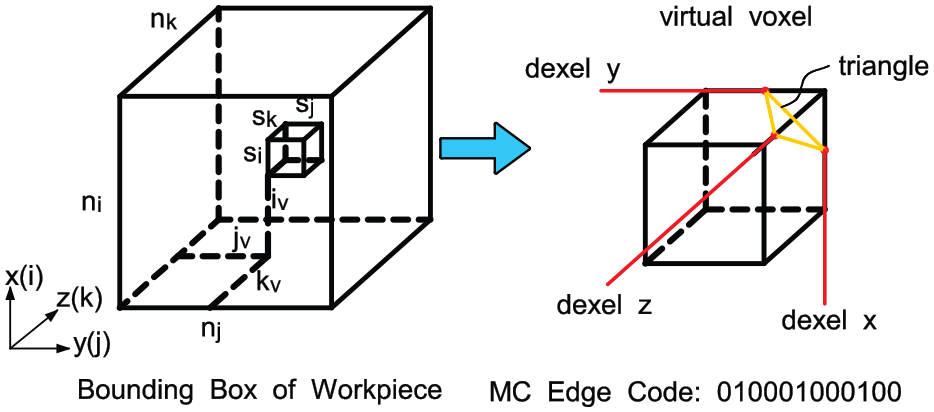
Encoding rules of virtual voxel and marching cubes edge code identifying.
By building virtual voxel model from tri-dexel, it is possible to apply the marching cubes (MC) algorithm in mesh generation for interactive visualization. Inside a virtual voxel, the state of point location on edge is estimated as shown in Figure 8. This state is represented as 12-bit binaries and every bit indicates that whether a certain voxel edge is occupied by a point. Taking this edge code as input, MC algorithm can find the order for connecting points. Compared with MC algorithm for distance field model, the step of edge points interpolation calculation is skipped.
For dynamic mesh generation, the simplest updating strategy is to rebuild all the mesh structure by MC algorithm. However, there is a small part of the workpiece that is intersected with tool during one simulation time step. To reduce repetitive calculation, the workpiece is divided into multiple parts for mesh updating. As illustrated in Figure 9, two models are divided into 2 × 2 × 2 parts which are labeled with different colors. It is obvious that the method of workpiece division can be used for complex geometry(cow in Figure 9(b)) and simple geometry (cylinder in Figure 9(a)). In Boolean operation, workpiece parts that intersect with the tool are marked and the MC algorithm is executed for these local regions. The influence of the count of workpiece parts on the calculation time is discussed in next section.
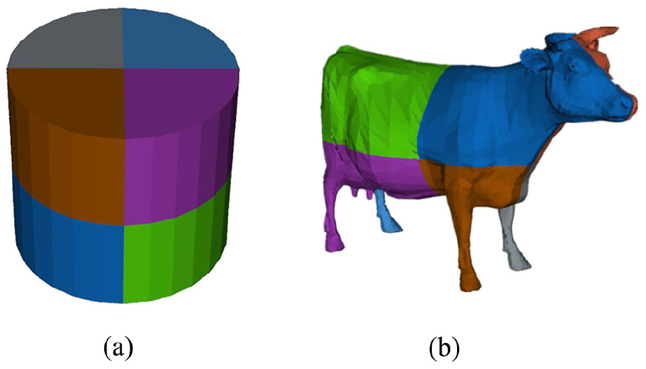
Results of multi-regions MC algorithm with the 2 × 2 × 2 workpiece division. (a) the cylinder model demonstrates the result applied to simple geometry and (b) the cow model demonstrates the result applied to complex geometry.
In summary, the methods of Boolean operation and mesh generation are optimized to decrease calculation time in tri-dexel-based machining simulation. In next section, quantitative analysis of efficiency optimization is presented. The efficiency of machining simulation is also verified comparing with the CNC communication data updating. By combining several optimization strategies, updating process of the simulation system is fast enough to follow the CNC to build an attractive Digital Twin system for machining process.
Case study
To verify the Digital Twin system proposed in this article, virtual simulation system is connected with a real machining tool to monitor the machining process synchronously. Experiments were conducted at COMAC’s manufacturing plant. The simulation system is developed with C++ programming language and OpenGL is used to render an interactive 3D window. SIEMENS 840D sl system is installed in the selected machine tool and supports OPC-UA and MTConnect. Virtual simulation that executes on a PC which is connected with the machine tool through net wire. Hardware condition of experimental environment is illustrated in Figure 10. The experiment shows that the virtual simulation system can display the workpiece geometry synchronously during the whole machining process and the interactive viewing is supported.
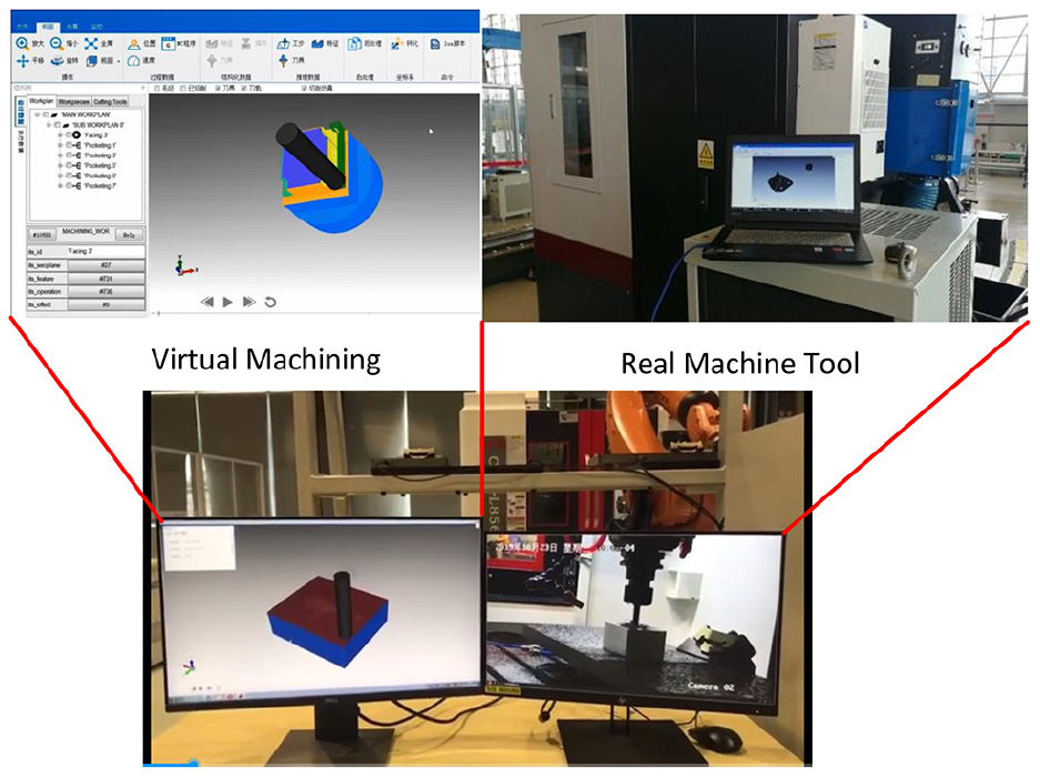
The experiment environment including virtual machining and real CNC machine tool.
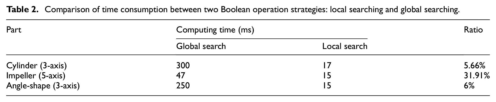
By implementing the optimization strategies, the efficiency of machining simulation is improved. First, time consumption in a Boolean operation is counted and the experimental results are compared for local searching method and global searching method. As listed in Table 2, it is obvious that the local searching method reduces the time consumption in Boolean operation by using tool bounding box. For the three tested parts, local searching method takes 5.66%, 31.91%, and 6.0% times to global searching. The calculation time of teh Boolean operation is limited less than 30 ms, that reserves sufficient computation time for mesh generation.
Comparison of time consumption between two Boolean operation strategies: local searching and global searching.
The relationship between number of subregions and time consumption of MC algorithm is plotted in Figure 11 to illustrate the influence of workpiece subdivision on simulation efficiency improvement. With the number of subregions increasing, the time consumption of MC algorithm is reduced. When the workpiece is divided into 2 × 2 × 2 subregions, the average time consumption of MC is 120 ms that is more than the connection updating time step, so the simulation cannot follow the CNC system. In the Digital Twin system, the number of subdivisions is set to 8 × 8 × 8, and the MC algorithm takes only 20 ms to generate mesh model.
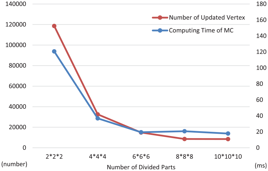
The computing time of MC algorithm declines with more divided parts number.
By using optimization strategies in Boolean operation and mesh generation, the time consumption of one simulation updating is limited less than 50 ms. And the CNC connection updating time step is stable, which is 100 ms. The remaining time can be utilized to execute the tool path matching algorithm and working step information extraction from STEP-NC data structure as mentioned previously. Therefore, the virtual machining simulation is executed synchronously with the real machining process. Three parts are tested in this Digital Twin system to verify the machining process intelligent monitoring. In Figure 12, the simulation results and machined parts are compared to demonstrate the effectiveness of the virtual simulation system.
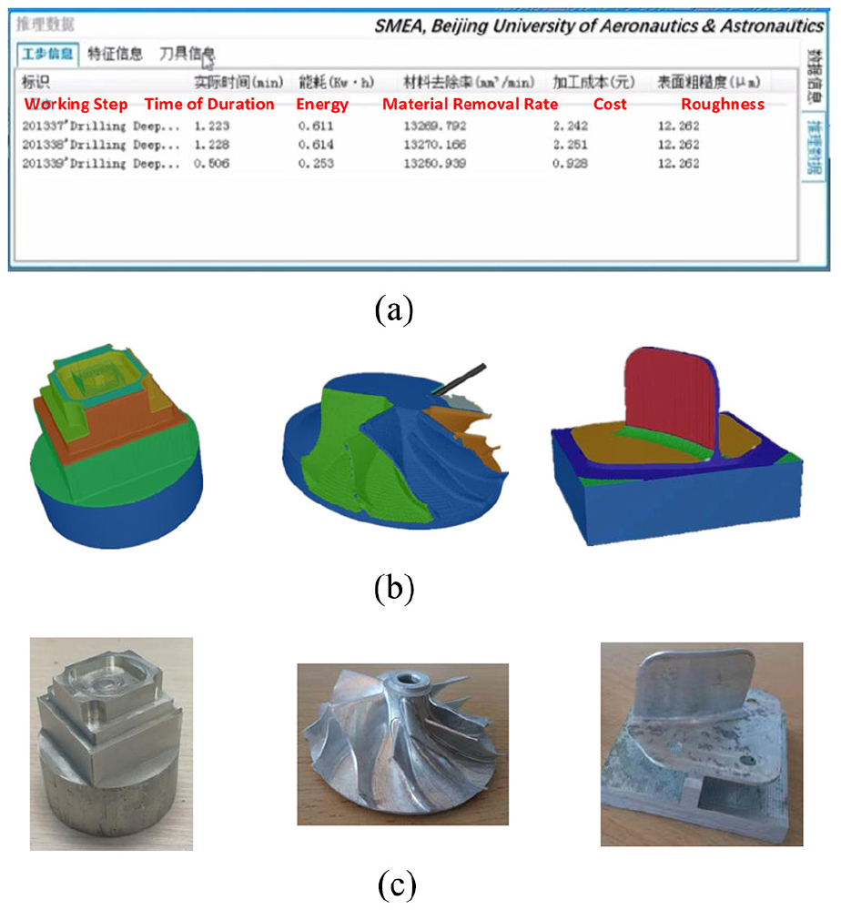
The simulation result from Digital Twin system and real machined part: (a) machining status monitoring and evaluation, (b) in-process workpiece geometry from machining simulation, and (c) real machined part from CNC machine tool.
With efficient machining simulation method, the machining process is monitored in a virtual environment. The experimental results are illustrated in Figure 12. Working step is recognized dynamically that indicates the machining progress. In Figure 12(a), some meaningful parameters of machining status are also evaluated including time of duration, energy, material removal rate, cost, and roughness. In-process workpiece geometry calculation is another kind of machining monitoring as shown in Figure 12(b). As an important function of intelligent machining, the monitoring information makes the CNC machining process no longer a black box. 37 In addition, monitoring information is an important data base for cloud manufacturing. 38 By integrating with network applications, machining status can be upload dynamically to the cloud for other intelligent applications.
Conclusion and future works
Digital Twin is a development direction of intelligent manufacturing and facilitates information fusion from design to manufacturing to make closed-loop manufacturing possible. The virtual machining system in digital twin environment is the most critical and difficult function. In this article, challenges for machining simulation in Digital Twin system are discussed which is quite different from the traditional off-line simulation. First, the virtual simulation system needs complete process data from CAM system for on-line tracking. By using the STEP-NC standard, the complete process data are exported automatically and read by the simulation system. Second, communication data from CNC are primary (cutter locations) and should be matched with the theoretical tool path. The k-d tree searching method is used to find the right part of tool path and the missing points during the communication updating step can be completed using interpolation. Third, the demand for high efficiency of machining simulation is more than off-line situation. The count of cutter locations is increased and the communication time step limits the available computation time for on simulation updating. To handle this problem, an optimized tri-dexel-based simulation method is proposed. The calculation is simplified in Boolean operation and mesh model generation.
The proposed Digital Twin system for machining is tested in the real manufacturing plant in COMAC. Both 3-axis and 5-axis workpieces are supported. The experiments show that the virtual simulation system can keep synchronous with the real machining process. Updating time in one simulation step is limited under 50 ms. Virtual workpiece produced by simulation is contrasted with the real part that proves that the virtual system can correctly reflect the shape of machined parts.
For further researching, there are some work that can be done to enhance the functionality of this system. First, the physical simulation can be integrated based on the efficient geometry simulation method. With the abundant physical state information, cutting force, surface quality, and tool wear will be estimated and it is useful for machining process planning and processing tasks distribution. Moreover, a cloud-based virtual machining monitoring platform can be constructed by combining this Digital Twin system with network.
Footnotes
Declaration of conflicting interests
The author(s) declared no potential conflicts of interest with respect to the research, authorship, and/or publication of this article.
Funding
The author(s) disclosed receipt of the following financial support for the research, authorship, and/or publication of this article: This research was supported by the Ministry of Industry and Information Technology (CN)(Special Program) and Commercial Aircraft Corporation of China Ltd.