
Abstract
As the piston ring is inserted into the bore, it is forced against the liner by radial tension, thereby creating a seal. Radial tension not only affects the piston ring’s seal, but also significantly influences its tribological properties. To investigate the effect of non-uniform radial tension of piston ring on the lubrication properties, a contact finite element model of piston ring and cylinder liner tribo-pairs is constructed in this study. The contact pressure distribution between the tribo-pairs is determined based on this model. The obtained pressure is then regarded as the non-uniform radial tension of the ring, which is fitted to a formula. The formula is validated in two ways. Firstly, its generality is verified by simulating several different piston rings using the contact model and comparing their results with the formula. Second, a test rig was designed and set up to measure the piston ring’s circumferential tension. To verify the formula’s accuracy, an equivalent principle model of distributed pressure and concentrated force was proposed. This formula is used as an initial force to modify the piston ring mixed lubrication model. Based on this model, the lubrication performance of the piston ring with uniform radial tension and non-uniform radial tension into consideration is investigated. The findings demonstrate that the piston ring radial tension is of significance to its lubrication performance and can be modified to lessen local friction and wear issues, particularly those related to the piston ring gap, and thus improve the dependability of the piston ring.
Keywords
Introduction
With the increasing need to improve technical indicators such as reliability and thermal efficiency in internal combustion engine (ICE), the piston ring-cylinder liner (PRCL) tribo-pair has become increasingly important in enhancing overall engine performance. Because the piston ring’s free shape deviates from a perfect circle and its outer profile is larger than the cylinder liner, elastic force is required for it to fit into the bore’s inside wall and form a primary seal.1,2 This research focuses on investigating the initial radial tension resulting from contact between the ring and bore, along with its impact on the piston ring’s lubrication performance.
The radial tension is a crucial factor that determines the sealing and lubrication performance of piston rings. If the radial tension is too large, it can result in severe system friction loss and abrasion, while if the tension is too small, contact between the ring and bore may be lost, leading to the appearance of an extra gas flow channel3,4 and blow-by. This can cause lubrication failure, oil consumption, and ultimately reduce the thermal efficiency and economy of ICE. Moreover, the distribution of piston ring tension plays a vital role in the tribological performance of piston ring/cylinder liner friction pairs.5–7 Therefore, it is of great significance to study the distribution of piston ring tension and its influence on the lubrication performance of piston ring/cylinder liner tribo-pair.
The radial tension of piston ring is related to its free shape closely. 8 Generally, the piston ring free shape is determined by the customed-designed radial tension. However, the ring free shape tends not to present according to the design requirements due to its elastic property. Therefore, it is very important to establish the contact model between PRCL according to the piston ring free shape to determine the radial tension of the actual piston ring. Some researchers9–11 established differential equations using the relationship between the radial deformation of the piston ring and the section bending moment. Further, the relationship between the contact pressure distribution and ring deformation was obtained through different correction methods, which was verified by experiments. Tomanik et al. 12 overcome the shortcoming that the current method could not identify subtle local pressure changes and proposed to use then optical devices to measure the ring free shape which was then taken as parameter input to calculate the radial tension of the ring. The effectiveness of this method was verified. Cheng et al.13,14 developed a three-dimensional analysis model of the piston ring and proposed a force release method to calculate the radial contact pressure distribution between PRCL. To verify the model, they used two methods: the comparative radial tension contact method and light tightness method, respectively. Baelden and Tian 15 developed a curved beam finite element model and used it to explain the non-uniformity of piston ring and cylinder liner contact pressure. However, this model is only applicable to the oil ring. Subsequently, Liu et al., 16 Liu and Tian, 17 and Bhouri et al.18,19 extended the theory to the compression ring. Akalin and Newaz 20 established the contact finite element model of PRCL and analyzed the influence of contact surface characteristics on contact stress.
The above research studied the radial tension distribution of piston rings in detail by simulation modeling and experimental methods. However, as an important performance parameter of piston ring, the radial tension distribution cannot only affect the contact characteristics of PRCL, but also the tribology and lubrication performance. This importance arises from the fact that the tribological behavior of PRCL tribo-pairs is dependent on the distribution of oil film thickness (OFT), which can be directly influenced by the radial tension distribution. Unfortunately, the above research failed to consider this relationship. For the tribological analysis of PRCL tribo-pair, plenty of research are available for reference. In previous studies, however, the main assumption of the PRCL lubrication model is that the PRCL system is axisymmetric for simplified calculation.20–23 From the point of ICE design, this assumption is too idealistic.
Moreover, under working conditions, the inner surface of the cylinder liner is subjected to high thermal load, leading to its deformation and causing the PRCL system to become non-axisymmetric. We have made corresponding achievements in this field. 24 In recent years, with the continuous development of the tribological performance analysis model of PRCL, scholars have begun to pay attention to the non-uniform contact between PRCL. Most of these studies focus on the circumferential non-uniform characteristics of the PRCL system caused by cylinder liner deformation.25–28 However, the circumferential non-uniform tension distribution of piston ring is not within the scope of research. Only a few studies15,16 pay attention to the influence of the piston ring circumferential non-uniform tension. These studies only focus on medium high-speed machine diesel engines with small bore, rather than low-speed two-stroke marine diesel engine (LTDE) with large bore. In addition, the Poiseuille derive oil flow along circumferential direction of piston ring was ignored, which makes the research on the non-uniform problem of PRCL system only exist in a non-uniform model geometry, rather than the lubrication.
This work is based on the research work mentioned above that was overlooked. Firstly, a transient mixed lubrication model of PRCL is established, taking into account the ring structure and circumferential oil flow inhomogeneities. Secondly, the assumption of ring uniform radial tension (URT) is abandoned, instead, the real ring non-uniform radial tension (NURT) is taken into consideration. To get the ring radial tension distribution, the parametric modeling of PRCL contact model is studied by the secondary development of ABAQUS based on Python language. This model is used to replicate the whole process of the piston ring being installed into the cylinder liner from the free state, to obtain the ring-bore contact force. Furthermore, a test bench was constructed to validate the simulation result, and the comparability of the test results with the simulation results served to validate the correctness of the results. The PRCL contact force is regarded as the ring radial tension, which is used as an initial force to input the lubrication model to improve the piston ring mixed lubrication model. This is the main innovation of this work. The establishment of this model carries great significance for the lubrication analysis of PRCL tribo-pairs in ICE, particularly for LTDE.
Mixed lubrication model
Piston ring mixed lubrication model
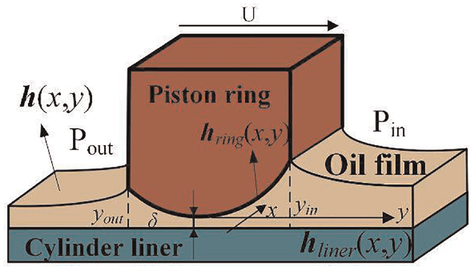
In this work, a Cartesian coordinate system was constructed as shown in Figure 1, in which the positive direction of the y-axis is from the bottom dead center (BDC) to the top dead center (TDC), the x-axis represents the circumferential direction of the piston ring. To establish the piston ring lubrication model, an average Reynolds equation that considers the surface roughness factors followed by Gaussian distribution is introduced to study the lubrication performance of the tribo-pairs,
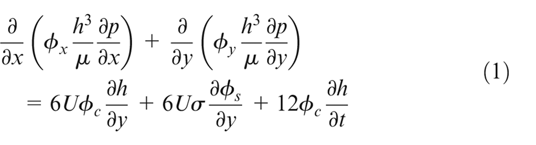
where h is the OFT, p the oil film pressure, μ the oil viscosity, U the piston ring reciprocation speed, ϕx and ϕy the pressure-flow factors, ϕc the contact factor, ϕs the shear-flow factor. The factors can be found at reference. 29 The clearance between ring and bore can be described as


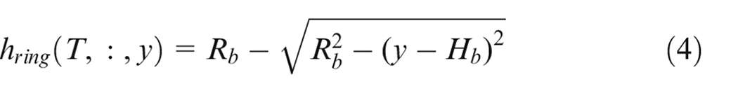
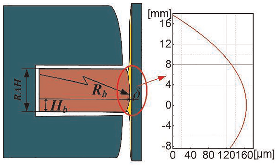
where, δ is defined as the clearance between the ring and bore, T crank angle, x the circumferential direction of piston ring, y the axial direction of piston ring, hring the piston ring running face profile as shown in Figure 2, Defliner the cylinder liner shape, Defring the piston ring deformation in the radial direction. For LTDE, the profile of the piston ring running face is usually a circular arc, therefore it can be described as equation (4).
Schematic diagram of OFT.
Schematic diagram of piston ring profile.
An elliptical bore is used in this work, which can be described as
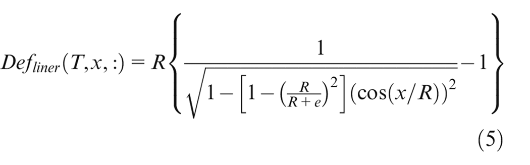
where Hb is the distance from the center of the circular arc profile to the piston ring bottom, Rb the radial of the circular arc profile, R is the nominal radial of the cylinder line, e the ovality of the elliptical cylinder liner.
Piston ring structure model
A structural deformation model of the piston ring is introduced in this study. The piston ring can be assumed to be a curved beam following Baelden’s 15 theory. The domain model of finite element form can be expressed as

where, [K] represents the ring stiffness matrix, {u} the generalized displacement vector of piston ring, {Fext} the external force vector. For each ring finite element, the element stiffness matrix
Force analysis acting on the piston ring.
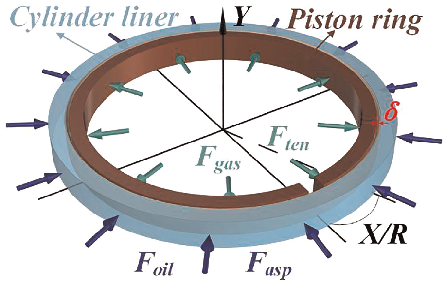
As was already mentioned, the forces per unit length acting on the piston ring running face are related to the OFT and the piston ring deformation. Therefore, the two forces can be expressed as
The force acting on the ring back can be obtained by the following equations.
In addition, the piston ring radial tension generated when the piston ring is compressed into a circle shape from its free state, is regarded as the fourth force. In previous studies,4,31,32 this force is usually assumed to be uniform along the circumferential direction. The assumption is acceptable in the axial symmetry model. However, when it comes to a detailed analysis of the impact of piston ring radial tension on the lubrication performance, this assumption no longer works. A detailed study of the radial force will be carried out in Section 2.5.
Asperity contact model
The asperities present on the two surfaces start to generate contact behavior and asperity contact force simultaneously, as the ring is less than 4σ separates from the bore. According to the simplified Greenwood and Tripp’s 33 theories derived by Hu et al., 34 the asperity contact model can be described as
Where pasp is the asperity contact pressure, E1, E2, ν1, and ν2 represent Young’s modulus and Poisson ratio of PRCL respectively, Kp, Ap, ω are constants.
Piston ring/liner contact model of finite element model
As the piston ring moves from a free state to an installed state, the radial displacement of the ring is too large to apply the small deformation theory. Compared with the nominal radius of the piston ring, the radial width of the piston ring is small enough, so the piston ring can be treated as a curved thin beam. Accordingly, the relationship between stress and strain of piston ring becomes linear and meets the conditions of the superposition principle. According to the Maxwell-Mohr theorem, 35 the deformation of any point on the piston ring that is forced by an external force can be expressed as follows:
Where, δrd is the radial deformation of piston ring, Fm the bending moment produced by the external force, Fm1 the bending moment generated under unit load, Fn is the axial force produced by external force, Fn1 is the axial force generated under unit load, Fr the radial force, Fr1 is the unit radial force; Area the area of the piston ring section, G is shear modulus, Kcoe is the section shape coefficient, s the arc length of the piston ring. The piston ring free shape can be obtained by adding together the nominal radius of the piston ring and the associated position deformation.
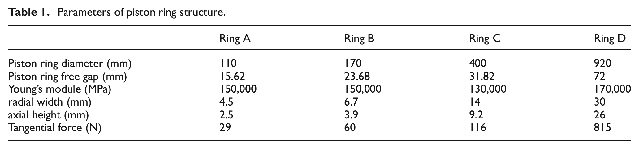
The piston ring’s free shape was measured using a profilometer and compared with the theoretical result, as shown in Figure 4. Since the piston ring is symmetrical, only half of it was measured for the piston ring’s free profile measurement. The shape of piston ring A is used to test the accuracy of the model, as illustrated in the picture, and the construction parameters of piston ring A are presented in Table 1. It can be seen that the result of this work and the experimental result match, which verifies the correctness of the piston ring’s free shape theory. The work ensures accurate geometric input for the PRCL finite element contact model.
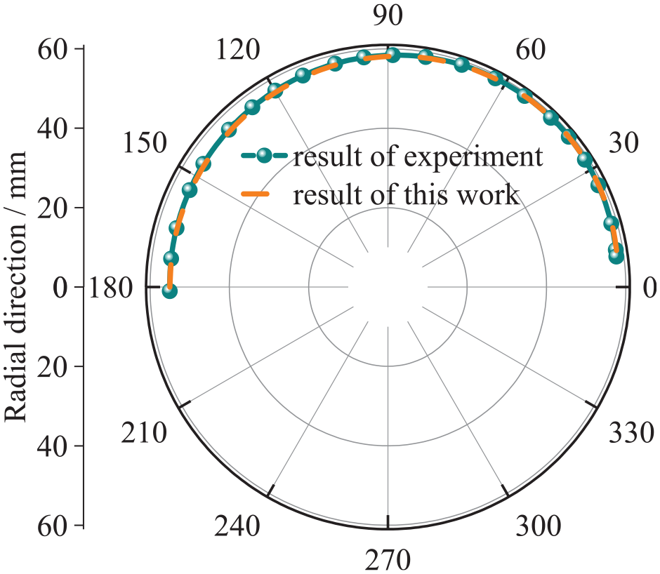
Verification of piston ring free profile.
Parameters of piston ring structure.
The 3D piston ring simulation model was established based on the piston ring’s free shape. Further, the finite element contact model of PRCL was established by ABAQUS simulation software, as shown in Figure 5.
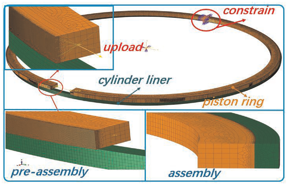
Piston ring/cylinder liner simulation contact model.
The PRCL is divided by hexahedral mesh. The nonlinear contact problem of the system is simulated using the augmented Lagrange method in ABAQUS. The model simulates the assembly process of piston ring through four analysis steps, which can be specifically described as:
(1) Loading process: Completely fixed constraints are applied to the 180° section of the piston ring. Then, applying concentrated force load to the open ends of the piston ring to cause it to close.
(2) Installation process: The degree of freedom in axial direction of the piston ring section is released and the displacement load is applied to make the piston ring installed inside the cylinder liner.
(3) Force release process: Gradually release the load so that the piston ring opens inside the cylinder liner.
(4) Constrain release process: Release all the constraints, and adjust the contact state between the piston ring and the cylinder liner to finally achieve stability.
Determination of the distribution of ring tension
The piston ring radial tension distribution function has been developed in various forms with good performance that can be applied directly as empirical formulas. However, significant differences exist between the various forms of empirical formulas. Therefore, the purpose of this work is to obtain the pressure distribution (treated as radial tension) between the ring and bore as the piston ring is closed to a round one from the free state by the establishment of the PRCL finite element contact model.
By post-processing, the contact pressure obtained from the finite element model, the radial tension curve in the circumferential direction of the piston ring can be determined. For an ideal piston ring, the radial pressure distribution is symmetrical about the line over the piston ring opening and the center of the circle, which can be treated as an even function. Consequently, various forms, such as cosθ, θ2, θsinθ, sin2θ, etc., can be used to form the piston ring radial tension. The optimal combination of these forms can yield the desired piston ring radial tension distribution function. According to the development of piston ring profile design,36,37 the piston ring tension profile should satisfy two main conditions: (1) the pressure distribution function should be as simple as possible, generally an even function; (2) in the angular range of (−π, 0), the fewer extreme points, the better.
Based on the above conditions, we obtained the tension distribution curve for half of the piston ring, shown in Figure 6. The input parameters are shown in Table 1, Ring B. It can be seen that within the 95% confidence interval, we obtained an empirical equation for the radial pressure distribution with respect to the geometric parameters such as piston ring gap, piston ring geometry, and Young’s modulus which can be written as the following form.
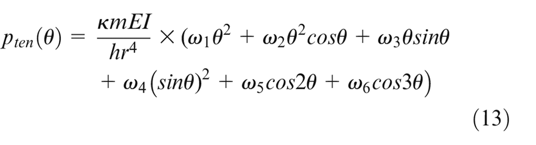
Where, m is the piston ring gap in free state, θ is the angle between any point on the piston ring and the ring gap; κ, ω1, ω2, ω3, ω4, ω5, ω6 are constants taken as 0.37, 0.92846, 0.9791, −0.02778, −1.55909, 0.41803, −0.08911 respectively.
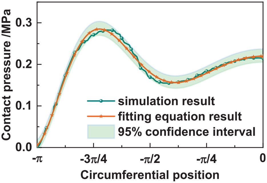
Comparison of piston ring radial tension between simulation and fitting equation.
Test system and model verification
Generality of the fitting equation
To inspect the generality of the fitting equation, secondary development of ABAQUS was carried out based on the Python language, and a parameterized ring-bore contact model was established. Radial tension distributions of several different piston rings were simulated according to the process described in Section 2.5. The parameters of piston rings are shown in the table below.
Figure 7 shows the comparison of piston ring radial tension between the simulation and fitting equation. It can be seen that for piston rings of different dimensions, the distribution trends and amplitudes of both results are close to each other. Therefore, the generalization of the piston ring radial tension fitting equation is verified.
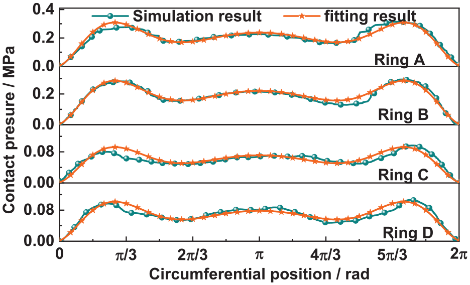
Results of generalization verification of ring radial tension fitting equation.
Test system and equivalent relationship
Since it is difficult to measure the contact pressure between piston rings and cylinder liner by test, a test rig is designed to measure several reaction forces at different positions of the piston ring. The idea of the test bench is to arrange a limited number of force sensors at different locations around the piston ring circumference, and the force sensors are in contact with the surface of the piston ring. The diagram of the test system is shown in Figure 8.
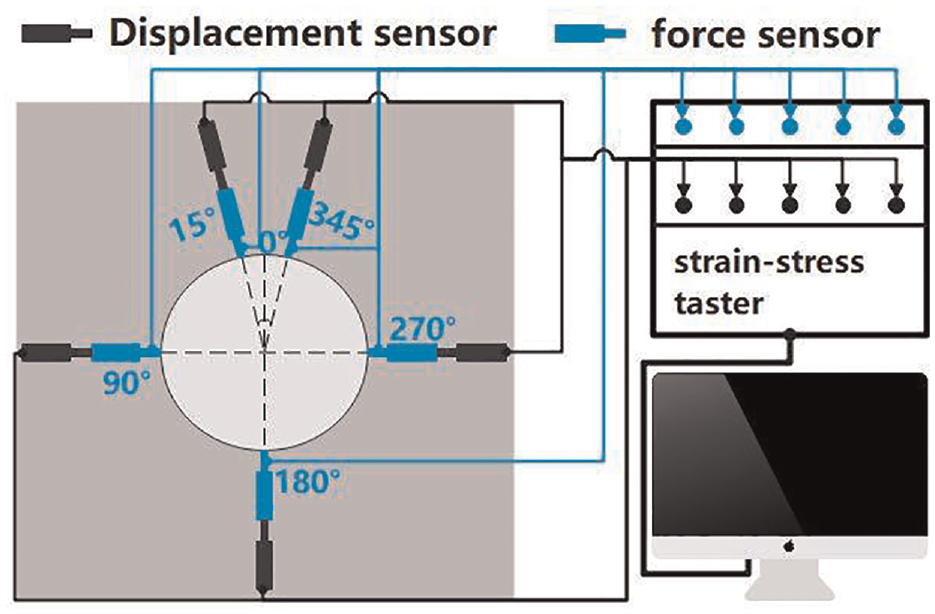
Test system.
More detailed information is shown in Figure 9. The test rig is equipped with five force sensors and five displacement sensors, of which eight sensors are symmetrically distributed, and two sensors are located with the symmetry axis. The fixing mechanism mainly includes the installation base, fixing bracket, rigid rod, sleeve, etc. The sleeve and rigid rod are connected by a pin, and the measuring range is controlled by controlling the length of the rigid rod extension. The measuring system mainly includes displacement sensors and force sensors. The displacement sensor is connected to the force sensor through the fixed bracket, and the two axes coincide. The displacement sensor can be used to measure the radial tension distribution of the piston ring when local deformation occurs in the cylinder liner by adjusting the displacement sensor. The force sensor is in direct contact with the part to be tested. Only force sensors are used in this research. The sleeve can be moved with the expansion and contraction of the rigid rod, thus adapting to the different sizes of the parts to be tested. The positioning system mainly consists of guide rail, turn table, and sliding block. The bar guide and the rotatable circular table are inscribed with scale lines. The four sliders can be attached to the bar guide by fixing pins and can be used to fix the piston ring.
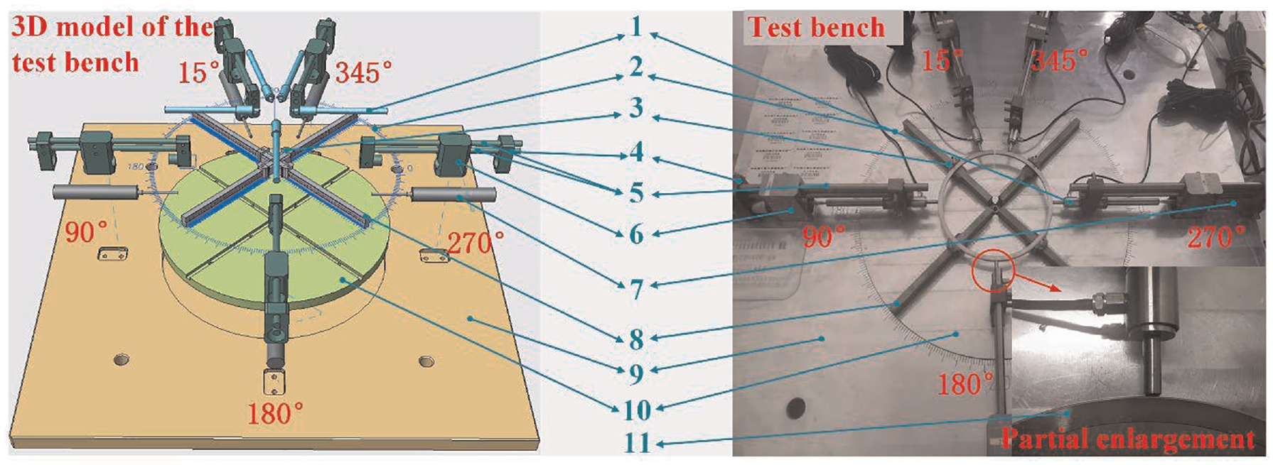
Piston ring radial tension test bench. 1. Force sensor. 2. Scale line. 3. Sliding block. 4. Sleeve. 5. Rigid rod. 6. Fixed support. 7. Displacement sensor. 8. Guide rail. 9. Installation base. 10. Turn table. 11. Test sample.
Before the experiment, the sliding block was fixed on the guide rail according to the nominal diameter of the piston ring and then installed the tested ring. The process is to simulate the piston ring installation into the cylinder liner. Subsequently, the force sensor was attached to the outer surface of the piston ring and fixed to release the sliding block. Force signals were recorded and saved on a computer.
Notably, the experiment resulted in bearing reaction forces measured in N, while the radial tension obtained from equation (13) represented distributed pressure forces measured in Pa. Therefore, it is necessary to study the equivalent relationship between the effects of the two types of forces to make the simulation analysis and verification more convincing.
To establish the equivalent relationship between the bearing reaction force and the distributed pressure force, this study draws on the finite element method in processing the distributed pressure and the bearing reaction force. 38 When a curved beam is subjected to distributed pressure force and concentrated force respectively, the equivalent load of the ith degree of freedom on the finite element can be expressed as
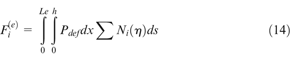
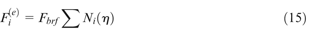
So, the equivalent relationship between the distributed pressure and the bearing reaction force can be descript as
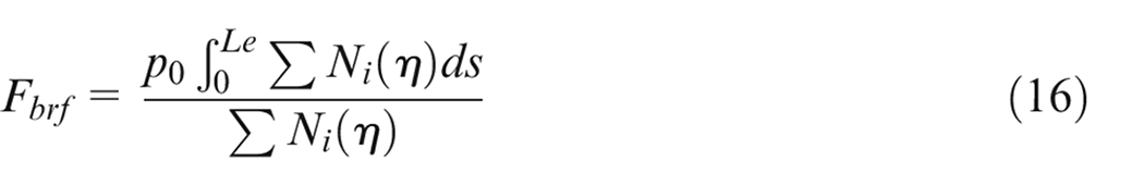
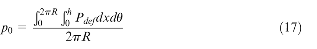
Figure 10 shows the loading diagram of two types of forces on a half ring. In Figure 10(b), measurement points 1 and 2 correspond to the position of the force sensor in the test bench, respectively.
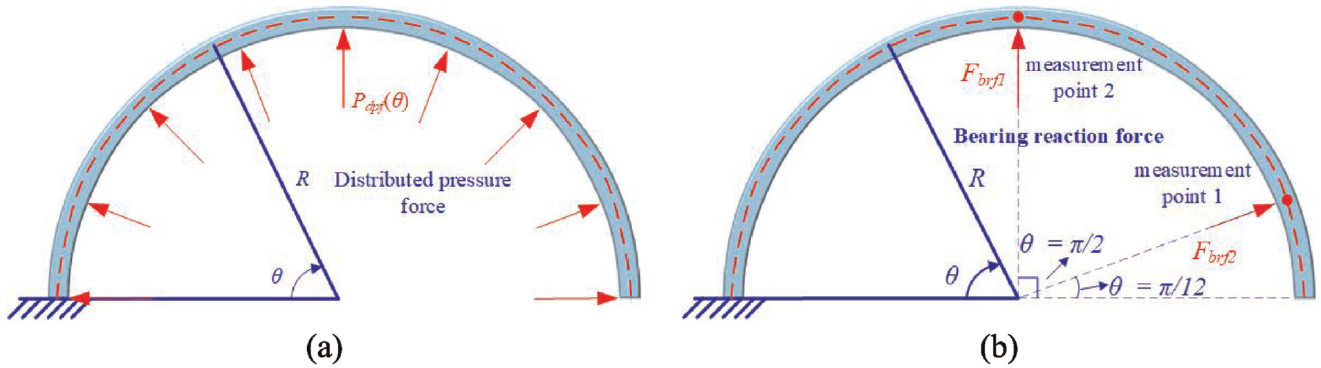
Schematic of force load applied: (a) uniformly distributed pressure and (b) concentrated force.
Figure 11 shows the radial deformation of the piston ring obtained by applying distribution pressure force and by using the bearing reaction force obtained by formula (17) to the curved beam, respectively. It can be seen from the figure that under the action of two types of forces, the piston ring deformation basically remains the same, there is a small difference only at position (degree from 0 to 30). This is because measurement point 1 to the free end of the piston ring is not subject to any external force, resulting in the curved beam radial deformation difference.
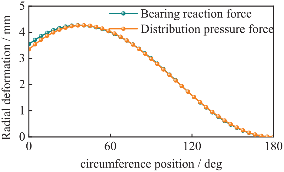
Deformation of curved beam under different load types.
Verification of piston ring radial tension fitting equation
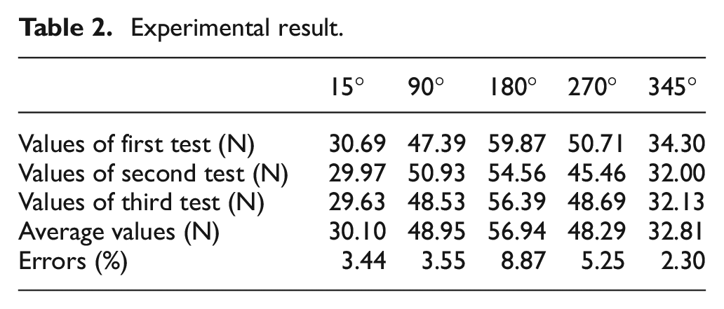
To ensure the accuracy of test results of the piston ring radial tension, several repeatability tests were conducted, which are shown in Table 2. The errors were calculated as the difference between the maximum and minimum values among three tests. The maximum error was at the 180° position. The errors arise due to the reference of the fixed slider position is the scale line which may cause an error of about 0.1 mm. Additionally, a small displacement error may have a large impact on the test results. Furthermore, the existence of sensor accuracy and inherent testing errors contributed to the data error, which remained within the acceptable range.
Experimental result.
The verification of the piston ring radial tension is achieved by setting the bearing reaction force and distribution pressure force equivalence method. This method helps convert the contact pressure between the piston ring and the cylinder liner into several concentrated forces at the corresponding position of the measurement point. The comparison results are shown in Figure 12. This calculation method assumes that the piston ring is a bending beam with its fixed end at the position of θ = 180°. Therefore, the force at the position cannot be obtained directly and needs to be obtained by force balance of the whole piston ring. As shown in Figure 12, the results of this work show good agreement with the measured results at the corresponding position. The maximum error occurs near 345° with an error of 8.75%. Considering the certain systematic error of the experiment, the errors obtained is within the acceptable range. This also verifies the correctness of the PRCL contact model and the fitting equation of the radial tension.
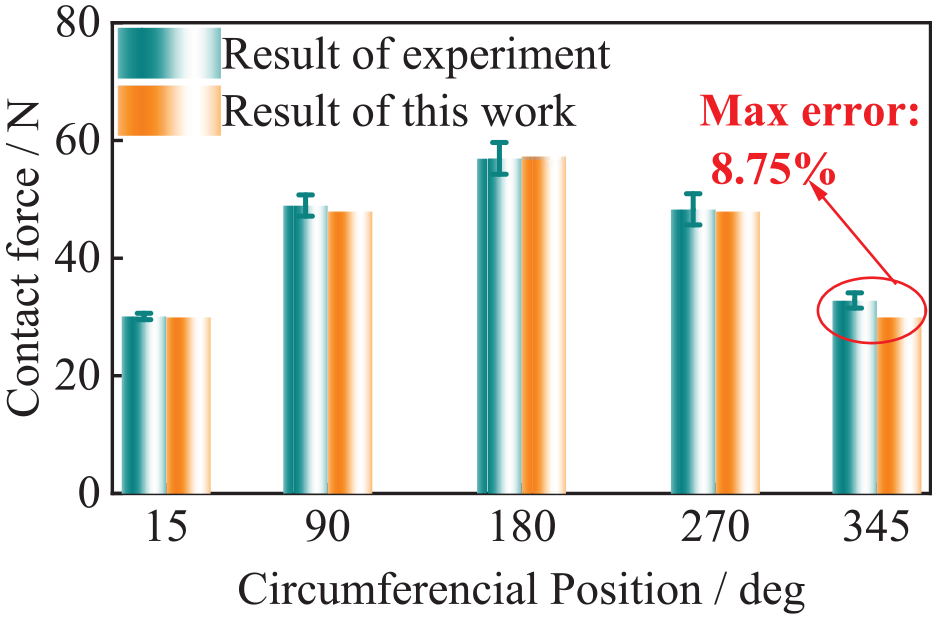
Verification of contact force.
Results and discussion
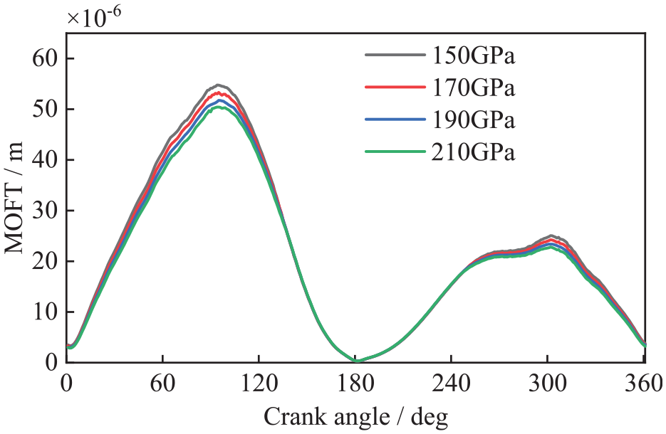
Parameter inputs
The parameters of a LTDE used in this research are listed in Table 3.
Parameter inputs.
Results analysis
Before the lubrication analysis of the PRCL tribo-pair, it is necessary to determine the relative position between the ring and bore. In this research, the two ends of the major axis of the elliptic bore are corresponding to 0 and π, respectively, while the two ends of the piston ring gap are located at the position of 0 and 2π. All subsequent results are based on this positional relationship.
Lubrication properties with URT and NURT into consideration
In this section, a transient mixed lubrication model is used to analyze the lubrication performance of the piston ring considering the radial deformation. Two different types of piston ring radial tensions are taken into account. The first one considers the URT into consideration, which is calculated by pten = Ften/R according to literature, 15 where pten is the radial tension pressure of the piston ring per unit length, Ften is the piston ring tangential tension force, R is the piston ring radius. The second one considers the NURT obtained via the empirical formula (equation (13)) developed in this research. The input parameters of the PRCL of the LTDE used for the work are shown in Table 3.
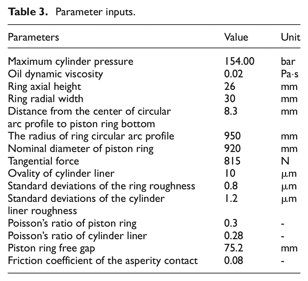
Figure 13 shows the distribution of OFT h(T, x, 0) between the ring and bore during a working cycle, the upper part of the figure shows the result considering URT while the lower part shows the result considering NURT. It can be seen from the contour plot that the OFT distribution varies obviously at all points, except those near the TDC, with the consideration of two types of different radial tensions. The OFT is an important parameter to determine the piston ring lubrication performance. Consequently, the variation in OFT distribution highlights the importance of accounting for radial tension when evaluating piston ring lubrication performance, emphasizing the necessity of considering NURT.
OFT distribution considered the URT and NURT, respectively.
Additionally, Figure 13 displays a more prominent difference in the OFT distribution between the ring and bore when considering URT and NURT. The position of minimum oil film thickness (MOFT) is different. The position of the MOFT is indicated by the green dotted line when URT is considered and by the orange dotted line when NURT is considered. It is obvious that the position of the MOFT between the ring and bore is significantly different near BDC and the middle stroke (0°–132° and 253°–360°) for the two different types of tensions. That is due to the fact that near the BDC, the gas pressure is lower enough and the piston ring speed is slow. Therefore, the dynamic pressure effect (
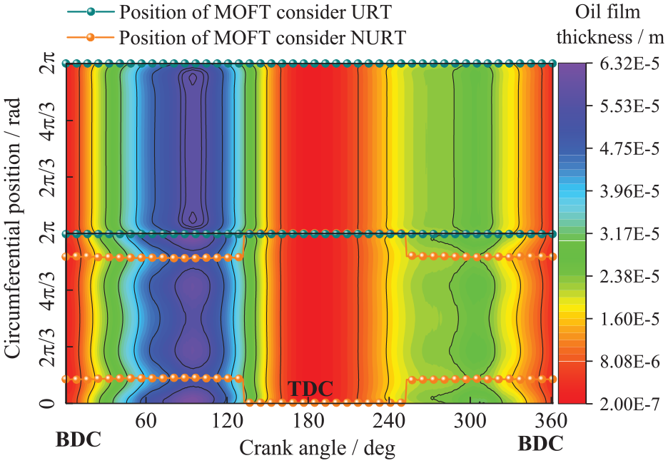
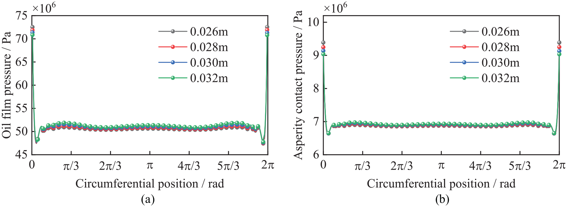
Figure 14(a) and (b) indicate the oil film pressure distribution poil(180, x, 0) and the asperity contact pressure distribution pasp(180, x, 0) along the circumferential direction of the ring and bore at the TDC. As shown in the figure, the maximum load carrying capacity of the oil film and the asperity contact pressure along the circumferential direction of the piston ring occurs at the piston ring end gap, as mentioned before. According to the average Reynolds equation (1) the oil film pressure poil increases with the decrease of OFT h, while the asperity contact pressure pasp is similar according to the asperity contact model. Moreover, considering the effect of URT, the maximum oil film pressure is 7.288e7 Pa and the asperity contact pressure is 9.228e6 Pa, while considering the effect of NURT, the maximum oil film pressure is 7.131e7 Pa and the asperity contact pressure is 9.132e6 Pa. By comparison, it can be seen that the oil film pressure and the asperity contact pressure are lower when taking the NURT into consideration. The comparison demonstrate that the piston ring radial tension is of significance to its lubrication performance. The piston ring radial tension can be modified to reduce the local friction and wear problem (especially those related to the piston ring gap), thus improve the reliability of the piston ring. Additionally, the results emphasize the importance of developing this model for piston ring structural design and low-friction design.
Comparison of results considered the uniform and non-uniform radial tension at TDC: (a) maximum oil film pressure poil(180, x, 0) and (b) maximum asperity contact pressure pasp(180, x, 0).
Influence of Young’s modulus
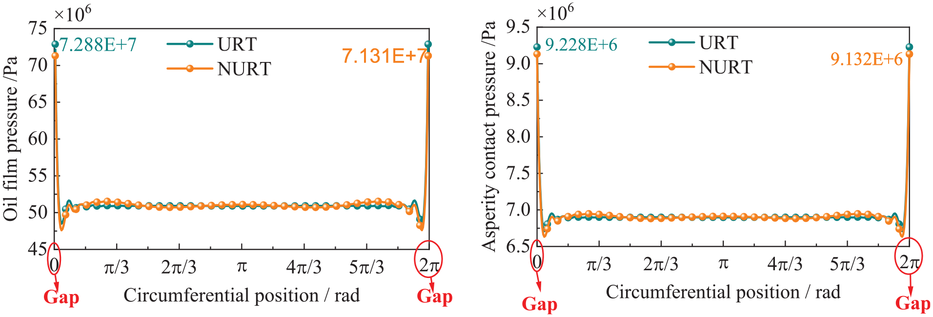
Figures 15 and 16 illustrate the effect of different ring elastic modulus on the MOFT and the average tribological properties of piston ring as a whole. As we can see, the MOFT decreases with the increase of piston ring elastic modulus, while the friction forces and friction loss increase. This is due to the increase of piston ring radial tension with the increase of elastic modulus, causing an increase in the combined external force on the piston ring according to equation (7), which is of similar conclusion with Ma et al. 39
MOFT of piston ring of different Young’s module.
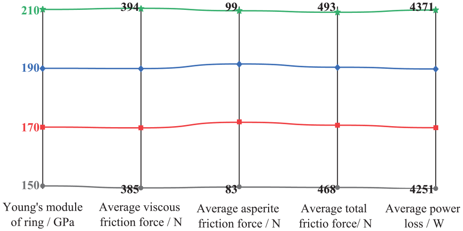
Piston ring average lubrication performance of different Young’s module.
To obtain more specific information, Figure 17 shows the variation of the maximum load-carrying capacity of oil film poil(180, x, 0) and the asperity contact pressure pasp(180, x, 0) at TDC. As we can see, the load-carrying capacity of oil film decreases while the asperity contact pressure increases with the increase of the piston ring elastic modulus at the TDC. This is because the increase of elastic modulus leads to the increase of the piston ring stiffness, which increases the deformation resistance of the piston ring. In a sense, the requirement for oil film bearing capacity is diminished by the increase in ring stiffness. Therefore, the maximum load-carrying capacity of oil film decrease as the elastic modulus increases. It is known from the asperity contact model that the increase of the piston ring elastic modulus also leads to the increase of the coefficient Ksap, which makes the asperity contact pressure increases significantly with the increase of the elastic modulus. Therefore, raising the ring’s elastic modulus will somewhat worsen the piston ring’s lubrication properties, whereas a smaller elastic modulus can ensure the ring’s lubrication performance under the premise of ensuring the mechanical properties of the ring.
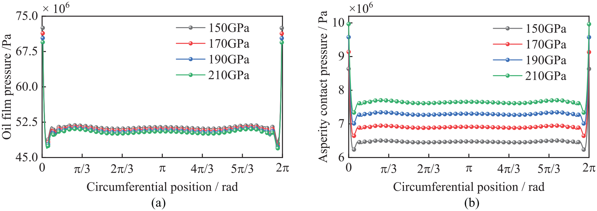
Comparison of results considered the uniform and non-uniform radial tension at TDC for different values of Young’s modulus: (a) maximum oil film pressure poil(180, x, 0) and (b) maximum asperity contact pressure pasp(180, x, 0)
Influence of ring cross-section
The cross-section of the piston ring directly affects the piston ring cross-sectional area moment of inertia I as shown in the expression of the unit stiffness matrix and equation (13). Thus, more likely to affect the ring stiffness and ring tension, so this section focuses on the effect of the radial width on the lubrication performance of the ring.
The effects of various ring radial widths on the MOFT and the average tribological performance are shown in Figures 18 and 19. The results reveal that with the increase of piston ring radial width the MOFT decreases while the friction force and power loss increase, which is due to the increase of piston ring radial tension and the combined external force on the piston ring with the increase of the ring radial width by the expression of unit stiffness matrix and equation (13). However, this growth is not particularly noteworthy in terms of average asperity friction force. The local distribution trend of the oil film pressure and the asperity contact pressure in Figure 20 further supports the aforementioned conclusion. Higher gas pressure retains stronger conformability in TDC, as Ma et al. 40 illustrated, in consequence, increased piston ring tension has minimal effect on the two forces. Therefore, it is sufficient to keep the existing design with the premise of ensuring the ring dynamics performance.
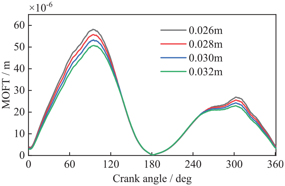
MOFT of different ring radial width.
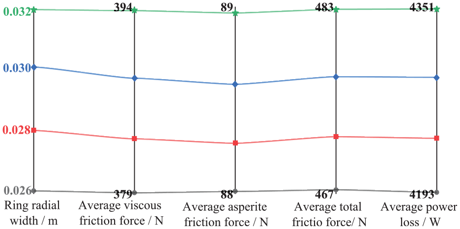
Piston ring average lubrication performance of different ring radial width.
Comparison of results considered the uniform and non-uniform radial tension at TDC for different values of cross-section: (a) maximum oil film pressure poil(180, x, 0) and (b) maximum asperity contact pressure pasp(180, x, 0).
Conclusion
In this work, the radial tension distribution of piston rings is investigated based on the 3D piston ring-cylinder liner contact finite element model, and then is used to modify the piston ring mixed lubrication model as an initial force. Base on this model, the lubrication performance of the piston ring with uniform ring tension and non-uniform ring tension into consideration is investigated and some conclusion can be gained as follows.
(1) In the present model approach, the empirical equation (13) developed in this study for the radial tension distribution of the piston ring has been demonstrated to be applicable across different scales, thus verifying its versatility and usefulness;
(2) A significant effect on the oil film thickness distribution is exerted by the non-uniform ring tension of piston rings, compared to the consideration of uniform ring tension. This effect is particularly pronounced in the middle stroke, where the velocity is higher, and the load-carrying capacity of the oil film is larger;
(3) The piston ring radial tension is found to be a critical factor affecting its lubrication performance. By adjusting the radial tension, the local friction and wear problem, especially in the piston ring gap, can be mitigated, leading to improved reliability of the piston ring;
(4) The Young’s modulus of the piston ring is observed to have a significant effect on the lubrication performance, while the radial width has a weaker effect. Therefore, proper material selection and geometric design of the piston ring are crucial in achieving optimal lubrication performance.
Further work
The simplicity of the model employed in this study has resulted in a formula for the radial tension of piston rings that may not be fully representative of all possible design and operational conditions. Hence, it is important to conduct further research in order to refine the formula and ensure its applicability to varied contexts, including different models and designs of low-speed marine engines, as well as different lap joint interfaces.
In future research, research should be directed toward two key areas. Firstly, special attention should be paid to the applicability of the formula for the radial tension of piston rings across different types of ring gap especially lap joint ring gap. Various ring gap can substantially influence the contact stress and deformation of piston rings, leading to variations in the distribution of the radial tension across the rings. Therefore, future investigations should look closely at the effects of different end gap on piston ring behavior, and develop a new and improved formula for the radial tension of piston rings.
Secondly, it is essential to investigate the suitability of different models of marine diesel engines with respect to piston ring design. As each engine type is characterized by unique operational conditions and design requirements, it is vital to explore the applicability of the current formula for the radial tension of piston rings across a range of engine models. Further research is needed to develop tailored formulas for the radial tension of piston rings that can address specific design and operational contexts.
In conclusion, future research should focus on refining the formula for the radial tension of piston rings to ensure its appropriateness to different types of ring gap and marine diesel engine, and to establish more comprehensive design guidelines that take into account the varied operating conditions and design parameters of these engines.
Footnotes
Appendix
Acknowledgements
The authors would like to sincerely express their appreciation.
Declaration of conflicting interests
The author(s) declared no potential conflicts of interest with respect to the research, authorship, and/or publication of this article.
Funding
The author(s) disclosed receipt of the following financial support for the research, authorship, and/or publication of this article: This research work is supported by the Study on Tribology and Lubrication Technology of the Marine Low-Speed Engine, the Lubrication Property Analysis and Experiment Verification of Highly-intensified Piston Assembly (No. DE0305), and the Shandong Provincial Natural Science Foundation (No. ZR2022QE183).