
Abstract
Reducing energy use and improving engine efficiency is a complex task however to date a continued reduction of lubricant viscosity has proved effective. Reducing viscosity decreases hydrodynamic friction and pumping losses however it can also exacerbate boundary friction losses. Detailed and representative component level experimentation is required to understand the effects of viscosity reduction on friction and opportunity for further optimisation. This paper presents a novel motored reciprocating Tribometer which has been developed to measure the friction between complete cylinder liners and three-piece oil control rings. The system holds individual or multiple rings stationary in a bespoke ring holder and reciprocate the cylinder liner thereby replicates the relative kinematics of the components in service. The new design has many operational advantages to identify and benchmark the individual contribution of oil control ring friction including near total isolation of oil ring-cylinder liner bore conjunction, pure rectilinear motion and use of full components without resorting to split liner/ring geometries. The experimental rig is used to measure friction at the three-piece oil control ring- cylinder liner conjunction when lubricated with two low viscosity lubricants. The results show prevalence of mixed regime lubrication across the speeds, temperatures and lubricants investigated. The oil control ring under investigation is shown to operate in mixed regime lubrication and at cold start the introduction of lower viscosity lubricants such as 0W-8 showed higher level of oil control ring-cylinder liner friction in comparison to the 0W-40. The information and experimental facility are of critical use for engine designers when considering the potential contradictory component efficiency behaviour when moving to ultra-low viscosity lubricants.
Introduction
A typical spark ignition internal combustion engine has an efficiency of between 30–40%. 1 A large proportion of the losses are thermal, but as much as 15–20% 2 of the overall losses can be attributed to engine friction. Almost half of which can be attributed to the piston assembly. The piston assembly losses can again be divided between the piston skirts and ring pack losses. Of which the oil control ring-cylinder liner friction accounted for 50–75% of ring pack losses.3,4
The oil control ring is comprised of one, two or three pieces. The constituent components of the three-piece design are a single piece expanding-separator and two thin segments that interface with the cylinder liner (6627 type. 5 ). By design the compression/expansion gasses exert considerable radial force on the top compression ring during combustion, restricting blowby. 6 The inter ring pressure directly above the oil control ring as result of the compression/expansion gasses that bypass the top rings and crankcase pressure on the lower face result in a negligible change in radial forces of the three-piece oil Control Ring due to their diminutive magnitude and thin axial cross section of the oil control ring segments.7–9
Extensive modelling and experimental research have been conducted regarding piston compression rings, 10 however, proportionally less consideration has been given to three-piece oil control rings. Of the three types of oil control ring, the single piece twin land oil control rings (6625 type 5 ) and two-piece twin land oil control rings (6626 type 5 ) have been the major focus of research. 11 Söderfjäll et al.12,13 showed a significant difference in friction between a stepped land oil control ring and a standard Euro 6 oil control ring (6626 type) using a hybrid engine-tribometer test rig. Research has also been carried out on two-piece oil control ring by, 14 however these are in essence a twin land with a coil spring expander (6626 type). Other research regarding twin land rings, such as surface texturing, has also been carried out 15 demonstrating a significant increase in hydrodynamic load carrying support is achievable with partial surface texturing. All this work however has concentrated mainly on the behaviour of 6626 type oil control rings.
In contrast to the twin land ring (6626 type), expander/segment ring often termed three-piece oil control rings (6627 type) ring segments can move reasonably independently even though linked as a single mechanism within the ring groove. The dynamical behaviour of the three-piece oil control ring are different to those of the twin land oil control ring. 16 This is most evident at the top dead centre and bottom dead centre points. At these points the individual segment can expand independently and remain in contact with the cylinder liner during piston secondary motion. Mansouri and Wong 17 show the effect of oil availability and piston clearance on skirt friction and piston secondary motion can be significant. In a similar fashion oil control ring groove wear geometry and rail face wear has been shown by 16 to significant effect oil transport through the rail liner interface. More recently 18 highlighted the importance of oil control ring twist and third land pressure to improve top segment scrapping during in the up stroke.
The experimental techniques that have been employed to measure two-piece oil control Ring friction (6626 type) include various floating liner and piston ring tribometer descendants.12,13,19,20 Westerfield et al. 19 used a floating liner engine to investigate two-piece oil control ring friction. The use of floating liner engines has the benefit of measuring complete ring pack and piston friction under conditions very similar to those found in application. However, challenges arise in separating the individual frictional contribution of each component, manufacturer of bespoke precision consumable components, engine vibration isolation and time intensive engine builds. Alternatively other studies have used piston ring tribometers to investigate sectioned Top compression ring and liner sections.21,22,23 These experiments face significant challenges associated with alignment and conformability of ring and liner sections which would only worsen if the same methodology were to be used for a three-piece oil control ring. Söderfjäll et al.12,13,20 presented a hybrid tribometer and floating liner system, built on top of a 6-cylinder engine. The test rig accepts full ring and liner components addressing the conformability and representative kinematics issue incurred by piston ring tribometers.
This paper outlines a novel experimental methodology where the conventional approach of a reciprocating piston is replaced by a reciprocating complete cylinder liner. This combines the advantages of piston ring tribometer and floating liner engine to achieve measurement access, isolation of component friction, repeatability, balancing, use of complete piston ring and liner components and representative relative component kinematics. In this paper the new test rig is used to show the frictional losses of low viscosity oil formulations on three-piece oil control ring friction. This type of experimental equipment has hitherto not previously been reported in literature.
Test rig design
A test rig has been designed to isolate the frictional contribution of the piston ring pack and cylinder liner interface. By holding the piston ring stationary in a bespoke holder and reciprocating the liner at 90° to the three-piece oil control ring contact surface an accurate measurement can be obtained. The test rig is designed to accept complete liner and ring components avoiding challenges created by sectioned liner and ring samples which have relieved hoop stresses inherent when they are cut or rolled. The improved conformity of the current design overcomes the issues discussed when using sectioned rings highlighted by.22,24
The test rig, shown in Figure 1(a) and (b), comprises of three major systems: the drive system, a heating system and the data collection system.
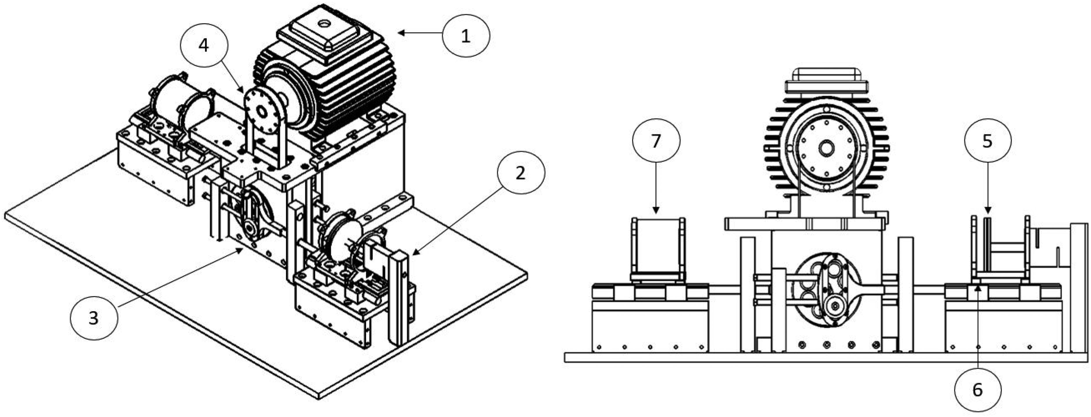
Test rig schematic.
Drive system
A 50 Hz three-phase 2.24 kW motor (1) rated at a maximum rpm of 2800 was used. The mount also contains the main drive system. The output shaft has been adapted to accept a rotary encoder (NI9401 5 V DC), with a resolution of 1500 pulses per revolution and max speed of 5000 RPM, positioned at the end of the motor drive and correlated to the linear motion of the reciprocating liner. The motor was mounted between two rails to ensure alignment of the motor pulley and drive system pulley.
The drive system comprises of a 30 mm toothed belt transferring drive from the motor “keyway located” pulley to the central shaft pulley mounted in the motor drive support unit (Figure 1 item 3). The two drive wheels and pulley are attached to the shaft and located by square drive pegs inserted into the shaft. The drive wheels are controlled in thrust by two flat end needle roller bearings (Thompson type). A hardened steel pin supporting a needle roller bearing to drive the yoke and arm is positioned off centre from the central shaft. The drive yoke (3) consists of three major components, the yoke, the yoke insert and the connecting rod. The Scotch yoke mechanism was selected to provide a compact and precise drive mechanism capable of closely replicating the relative piston ring cylinder liner kinematics. Dynamically the mechanism minimised excitation of the system in the direction normal to the test bench as the out of balance mass in this direction is limited to that of the pin. The system was completely counterbalanced using a mirror of the mechanism. The reciprocating components of the assembly are light weighted to reduce the joint forces and inertial torque. A hardened Steel insert is used to provide a wear resistant surface to the Aluminium Yoke.
The liner carriages (6 &7) are mounted on linear race low friction bearings running on hardened steel rails. The carriage consists of a base plate and two machined end plates that locate and support the liner. The rails on which the carriage reciprocates are mounted on an aluminium sump.
Heater system
The heating system consists of an insulated multi-plate block secured to the carriage box and contoured to allow the carriage to reciprocate inside (insulation not shown in image for clarity purposes). Six 300 W pencil heaters are inserted into the layer plates of the heater block and two in the carriage support. The block and support are heated, by conduction, to be stored and subsequently transferred inward to the reciprocating liner and shuttle. Four of the heaters are shown in Figure 2(a), Heater H1-3 are located in the heater block, and H4 in the carriage support structure. The remaining 4 heaters are distributed in the same manner of other side heat block and carriage support structure. All of the eight of pencil heaters are controlled by a heater controller.
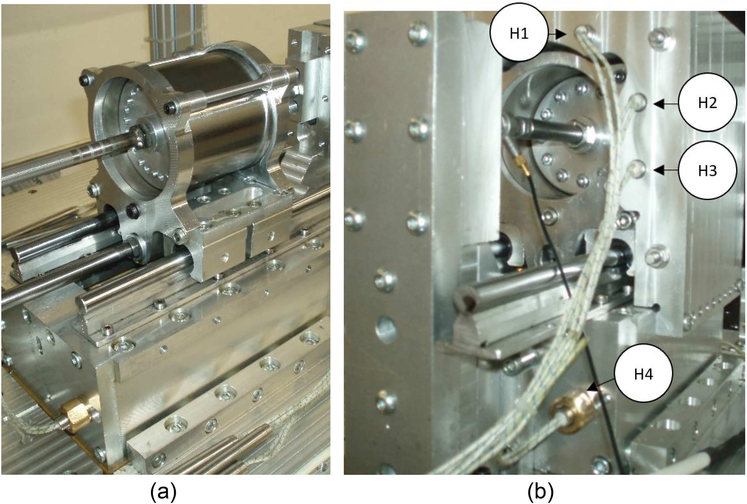
Test rig images (a) liner shuttle and ring holder assembly (b) heat block, liner shuttle and ring holder assemblies.
Data acquisition
A rotary encoder (NI9401 5 V DC), is positioned at the end of the main motor output shaft with a 0° degree rotation aligned with TDC reversal. This can then measure, by degrees of rotation, the position of the liner throughout its stroke. A piezo electric compression and extension load cell is routed through a signal conditioner that allows data to be collected via Lab View software. The low mass ring holder and ring holder support and high stiffness of the load cell ensures the natural frequency of the axial vibration mode of the friction measurement system is sufficiently high to avoid associated complications. The ring is held in a bespoke 2 piece disc, as seen in Figure 3, connected to the load cell. Any piston skirt friction found in floating liner test is all but eliminated with only minor viscous drag from the ring holder-cylinder liner interface. Initial experiments were conducted without an oil control ring to ensure this. The replacement time of ring(s) and cylinder liner(s) is considerably reduced in comparison to engine or floating liner tests and the load cell calibration can be performed at any time during testing.
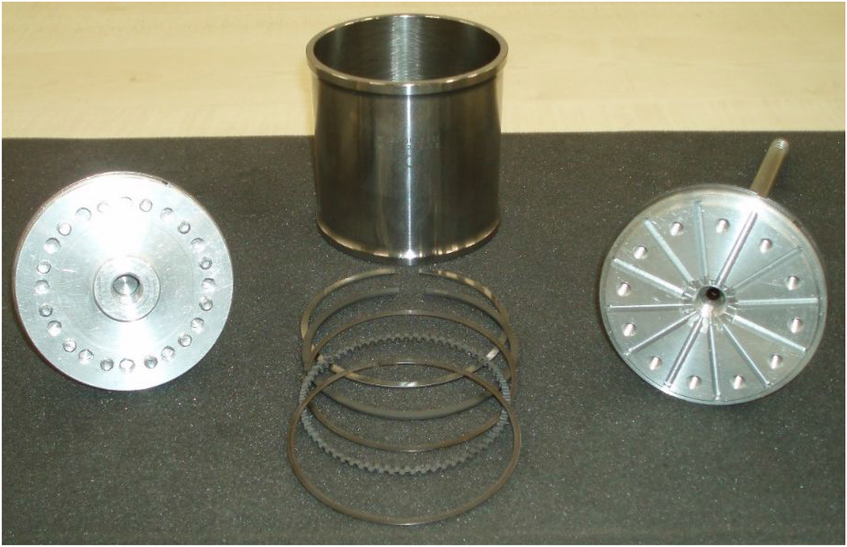
Test samples including oil control ring, ring holder and cylinder liner.
To facilitate accurate calibration of the load cell, seen in the top right-hand corner of Figure 1(b), a connection, via a cantilever arm, is positioned in alignment to a deadweight loading plate. This is connected to the load cell via a flexible connection running over low friction pulley wheels. Incremental masses were added to the loading mechanism and readings taken. This procedure is conducted at the beginning and end of all test sessions to ensure consistency of data during experiments. The cycle average friction repeatability of measurements for a three-piece oil control ring (removed and refitted before each measurement) and cylinder liner has a standard deviation across all measurements of 0.73 N.
Specimens
The lubricant, cylinder liner and oil control ring test samples used in the experiments are described in the following sections.
Cylinder liner
The cylinder liner is manufactured from 19MNV6 stress relieved steel with Nickel Ceramic Coating with a 30° crosshatched surface texture. The liner dimensions are, 80 mm bore with a 60 mm stroke. This represents a 1200cc four cylinder in-line engine. The test rig running at 1200 rpm will give a mean piston speed of approximately 2.7 m/s. The physical liner, ring pack and ring disc can be seen in Figure 3.
The Ra (Arithmetical Mean Height) and Rq (Root Mean Squared) roughness values for the oil control ring segment and cylinder liner were measured before and after use. This was done to establish any potential wear or alteration to the core surface roughness that may occur to either the piston ring or the cylinder liner.
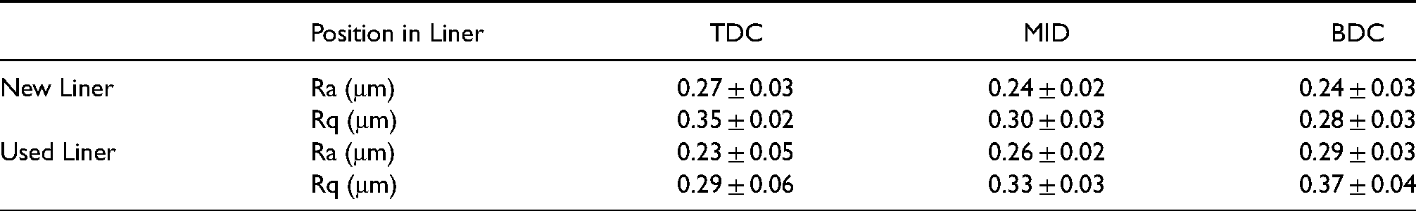
Table 1 show the Ra and Rq roughness values of new and used liners. The measurements were taken to determine if any change in the surface roughness height distribution occurred during the experiments. The liner was measured by TallySurf (CLI 2000) at three points along the axial length in the areas of TDC, BDC and Mid Stroke. Each position along the length of the liner was measured in turn at three equispaced circumferential locations. The measurements were conducted over a 6 mm length in the direction of sliding ensuring full coverage of the TDC and BDC regions.
New and used liner. Ra Rq values at TDC, BDC and Mid Stroke.
Oil control rings
A steel 100 series (6627 type) 25 three -piece oil control ring produced by Nippon Piston Ring Corp was used in the current study. The two segments have a nitrided contact face. The expander was the waveform type as shown in Figure 3. It is important to note that the expander supports the segment and exerts a small amount of tension on the segment to the liner surface. This is in conjunction with any elastic tension of the segments. The roughness of the rings measured before and after the rings were run are shown in Table 2.
Segment contact face roughness.
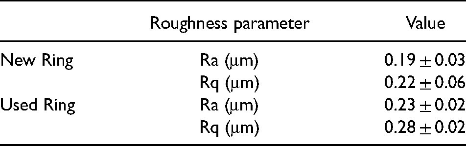
It can be observed from the data collected that only a small change in segment contact face roughness occurs during the experiments. Visscher et al. 26 also observed a small increase (0.012 μm) in oil control ring rms roughness during the first 32 h of their engine test. Ring groove tolerances were produced to prevent relative angles forming between the ring and the groove (ring twist) but allowing rotation and expansion. The segment contact face width axial profiles taken opposite to the ring end gap are shown in Figure 4 for a new and worn oil control ring segment.
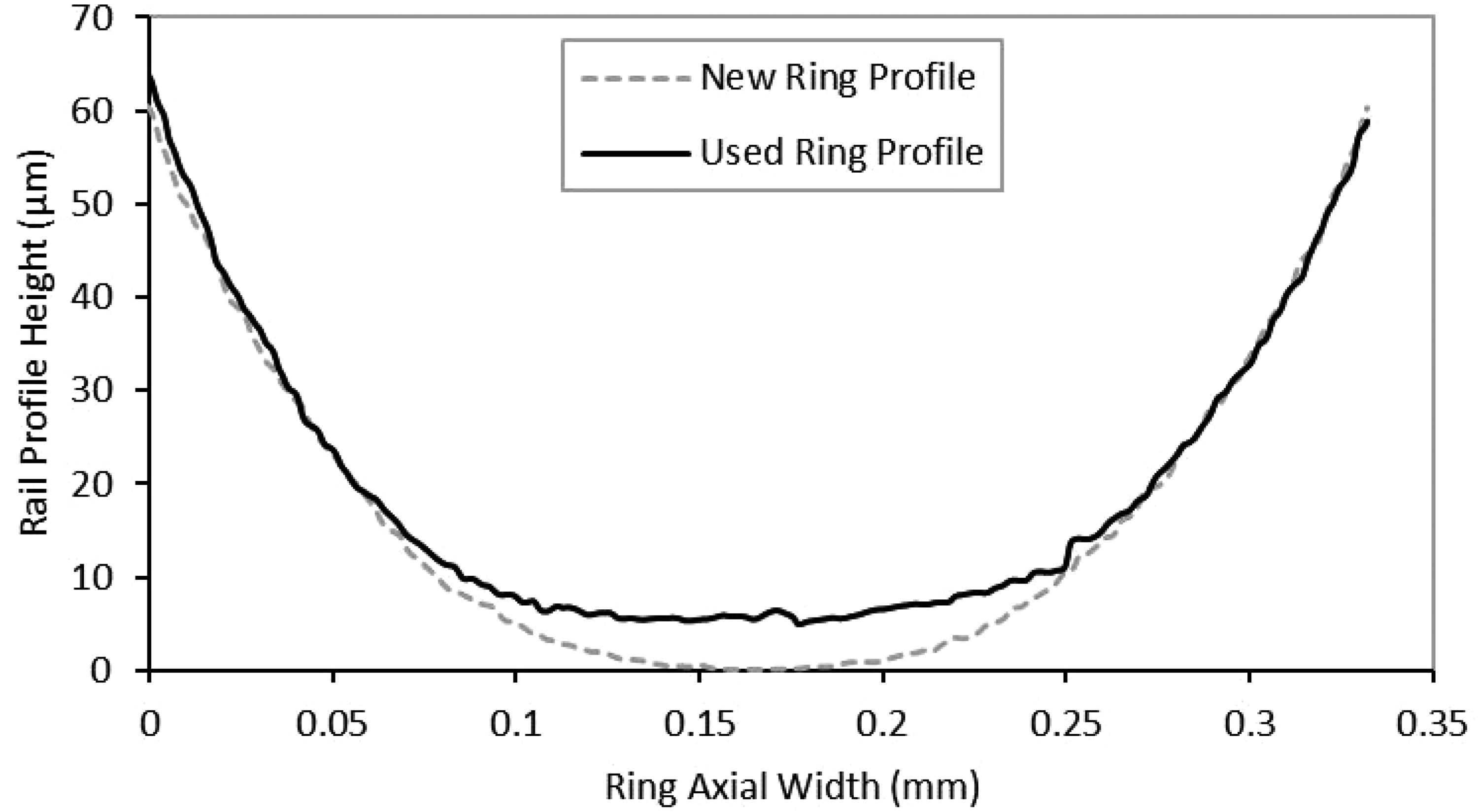
Oil control ring segment contact face profiles.
Lubricants
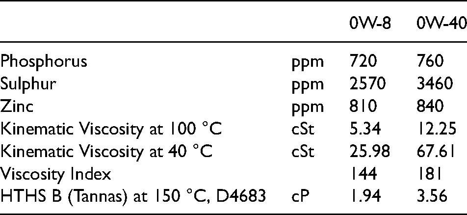
The Lubricants and relative viscosities that were used in the test can be seen in Table 3. The lubricants used in the experiments contained similar additive packages, with the only significant variable being that of lubricant rheology.
Lubricant viscosity.
Methodology
Prior to initial installation of the three-piece oil control ring, the ring disc holder, and liner were thoroughly cleaned using petroleum ether to remove all traces of lubricant and wear debris. On reassembly of the three-piece oil control ring the ring groove was flooded with the chosen lubricant. The end gaps of all three of the oil control ring components were radially staggered at 120° in the ring grove. As a reference point the expander end gap was placed at the 0° position. This was done to ensure equal static ring forces were distributed against the liner face. This also served to evaluate any rotational movement that may occur with any of the ring components during operation.
As the ring, ring disc holder and ring disc shaft were removed from the liner, and its interconnection to the load cell separated at every change in position of the ring, the removal of lubricant on both the ring disc and cylinder liner was carried out. Using this combination of settings consistently repeatable results were obtained during all tests.
To ensure the newly fitted ring was run in the rig was then motored at 500 rpm for five minutes, following the constant speed running the rig speeds were increased and decreased between approximately 300 and 1200 rpm. The rig was kept running and was not returned to stationary at any point during the individual tests.
Further lubricant was added to the liner and ring interface with the ring running to ensure a fully flooded contact inlet was maintained during the experiment. The rig was stabilised for 15 s at a constant 300 rpm. Measurements were taken over three individual five second periods with five second intervals between each measurement.
This procedure was repeated for 600, 900 and 1200 rpm. Following the measurements the rig was gradually reduced in speed to 300 rpm and shut down.
Results
Ambient temperature friction characteristics
The aforementioned test rig and experimental methodology were applied to demonstrate the test rig capability by determining the oil control ring-cylinder liner frictional behaviour when serviced by two low viscosity lubricants. The experiments were conducted at an ambient temperature of 20°C and elevated temperature of 80°C which are representative of an engine cold start and steady state operation respectively. The tests were conducted at cranking speeds of 300 engine RPM up to a light cruising speeds of 1200 engine RPM.
The crank angle resolved friction trace for 300 and 600 rpm serviced by the 0W40 lubricant is shown in Figure 5. The thin lines either side of the bold average line represent plus and minus one standard deviation. The standard deviation is crank angle specific and is taken from at least nine tests including at least 3 reassemblies and fitments of the oil control ring. A reduction in friction is shown to take place across the stroke and could be attributed to increased lubricant entrainment and load carrying capacity and during the deceleration phase a benefit from squeeze film effects. The magnitude and shape of the crank angle resolved measurements is similar to those obtained through floating liner engine testing conducted by Westerfield et al. 19
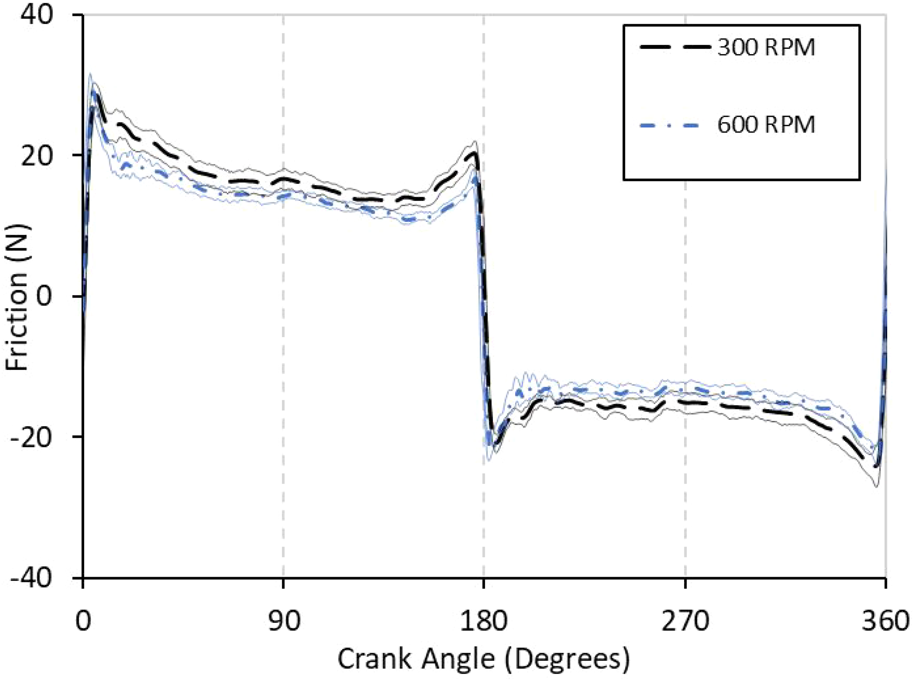
0W40 At 20 °C 300 and 600 RPM.
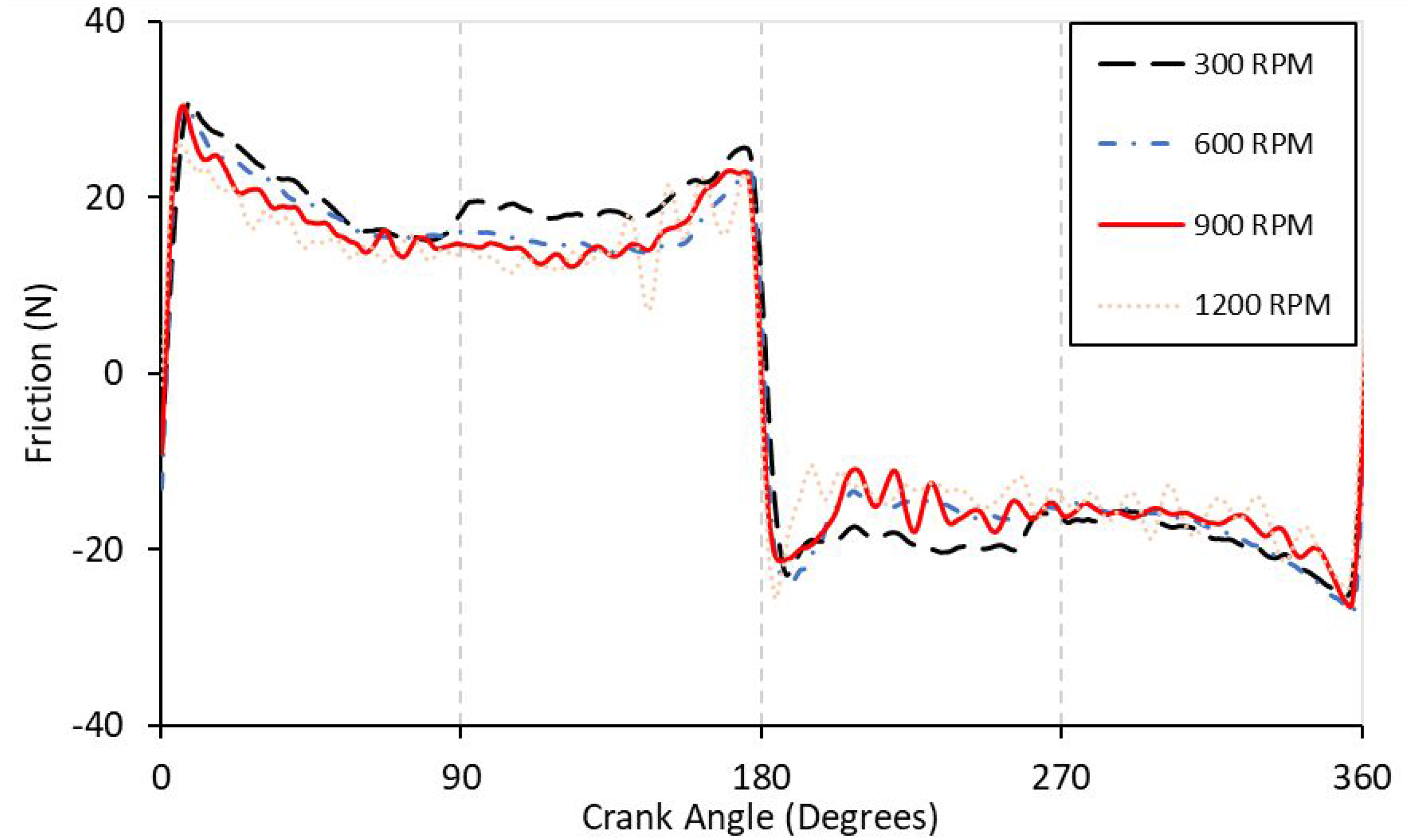
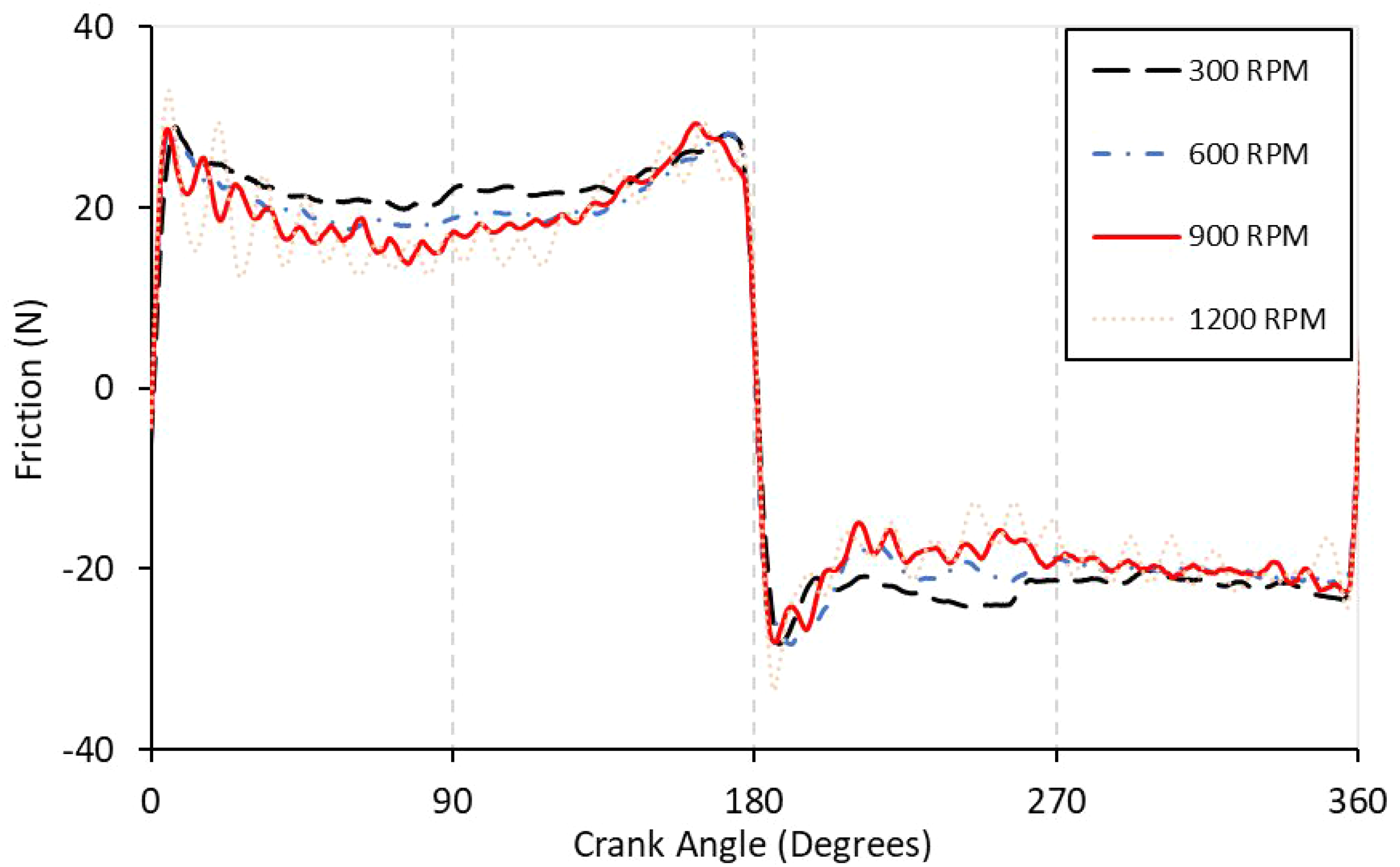
In Figure 6 the frictional behaviour for each of the 4 speeds investigated when lubricated by 0W40 oil are presented. The most significant change in the friction traces is the transition from high boundary friction at reversal to a mixed regime lubrication at mid-stroke. Overall, the results are across the speed range are very similar in trend an magnitude. This result is in agreement with Westerland et al. 19 who used the floating liner technique to measure an almost constant friction coefficient across the mixed regime lubrication region of stribeck curves for a similar three-piece ring.
0W40 At 20 °C 300, 600 and 900 and 1200 RPM comparison.
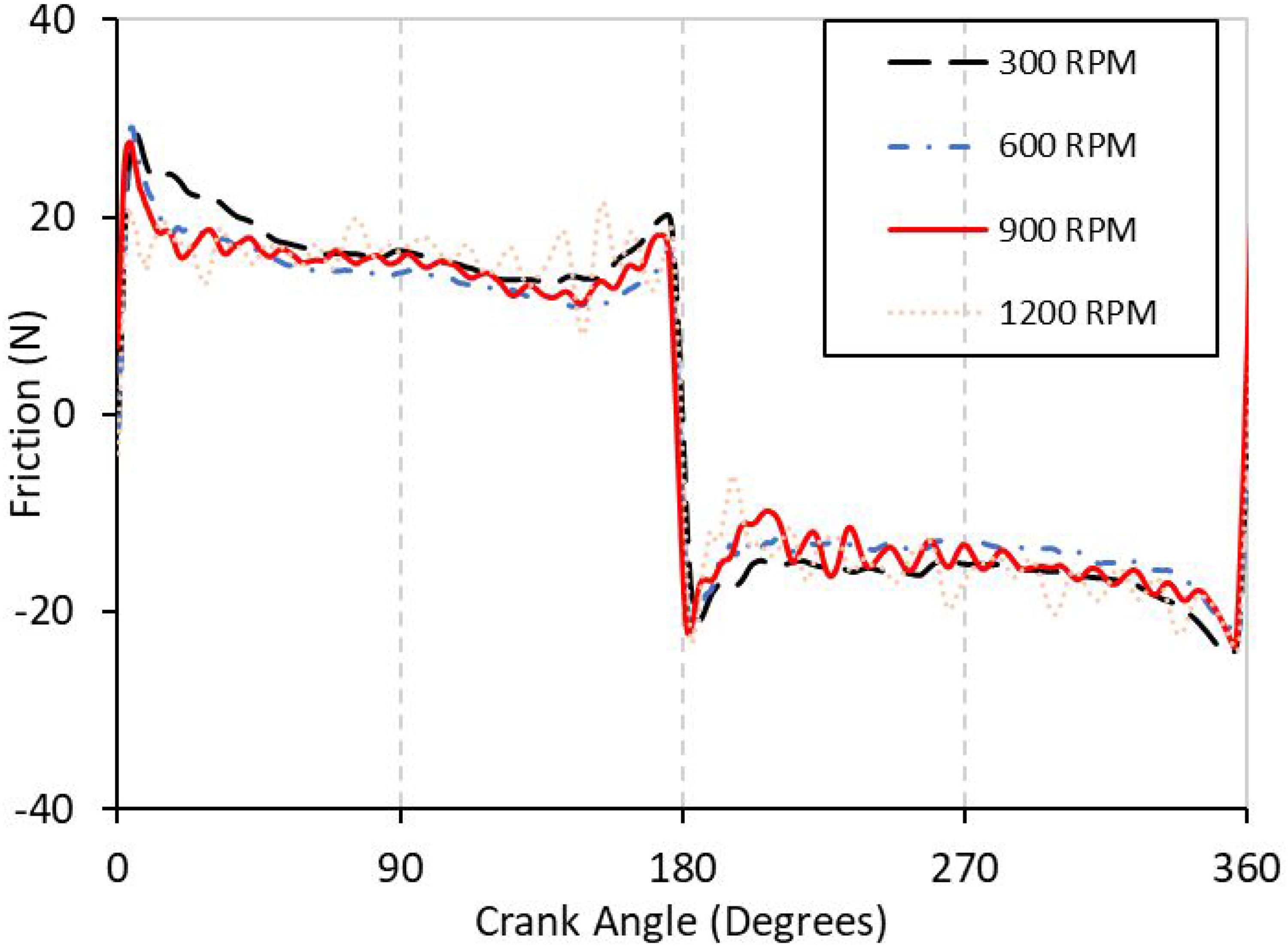
A comparison of the friction traces for the 4 chosen operating speeds when lubricated by the less viscous 0W8 oil is shown in Figure 7. As with the results for the 0W40 at ambient temperature the minimum friction occurs near to mid stroke and the maximum at reversal which is consistent with mixed regime lubrication. It can also be noticed that as the speed increases the transition from peak reversal friction to a reduced mid stroke friction value occurs earlier in the stroke.
0W8 At 20 °C 300, 600 and 900 and 1200 RPM comparison.
The traces shown in Figure 8 show the friction data for 0W8 and 0W40 lubricants at 600 RPM. The viscosity data for each is presented in Table 3. Again, the thin lines either side of the bold average line represent plus and minus one standard deviation. It can be seen from the results that the less viscous 0W8 lubricant gave higher friction values than that of the more viscous 0W40 lubricant. This behaviour is consistent with mixed regime lubrication, during which increased viscosity serves to increase hydrodynamic load carrying capacity and as a result reduce asperity frictional losses. In addition, the higher viscosity is also shown to reduce boundary friction during the deceleration phases this could be the result of an enhanced squeeze film load carrying capacity which mitigates asperity contact and boundary friction.
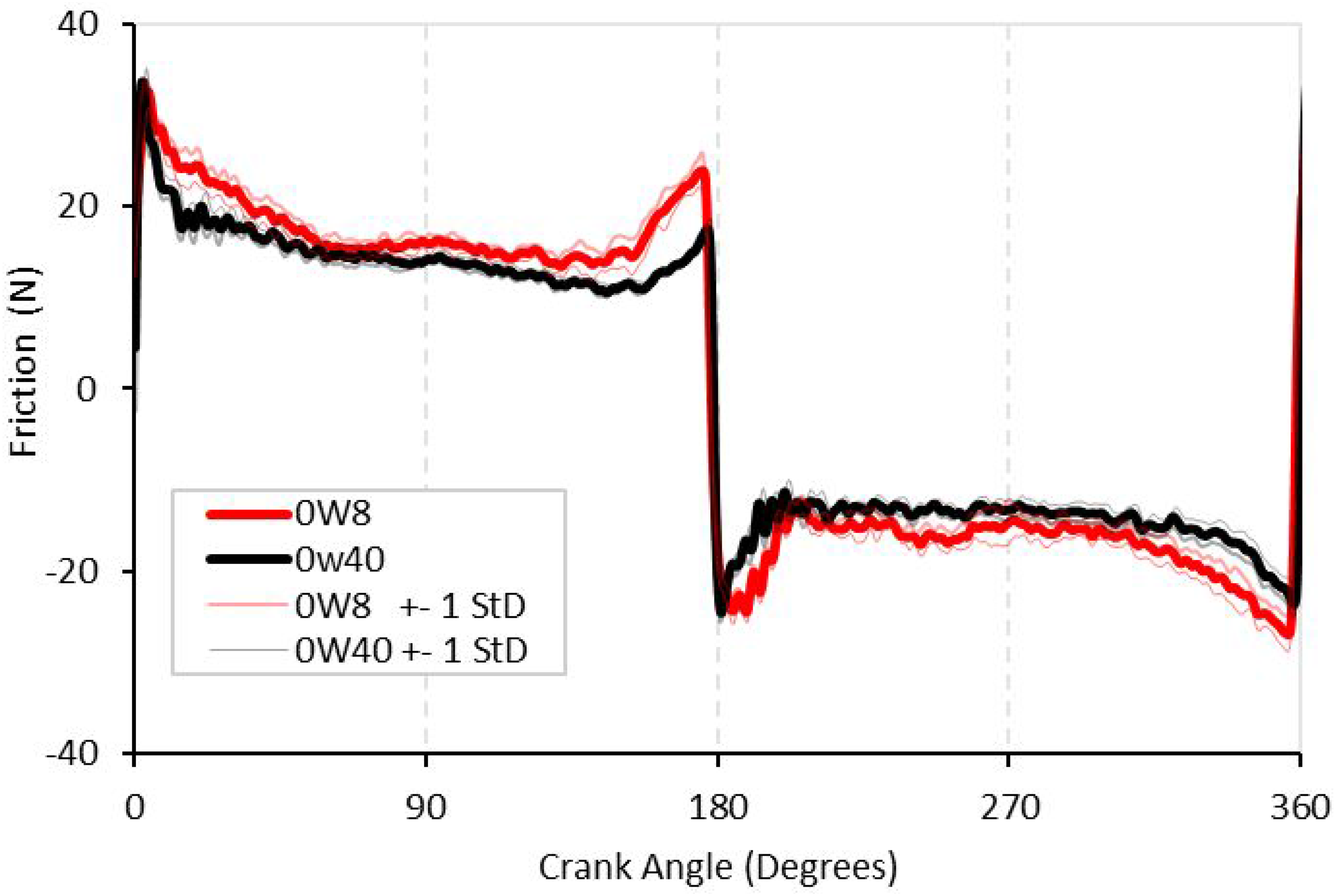
Crank angle resolved friction for 0W8 and 0W40 at 20 °C at 600 rpm.
The parasitic frictional power loss for the oil control ring lubricated by the two lubricants investigated is shown in Figure 9. The mid stroke frictional power losses are greatest due to the high relative surface velocities at this location in the stroke. The reduction in mid-stoke friction as a function of lubricant viscosity is shown to be the key differentiation for component parasitic power losses.
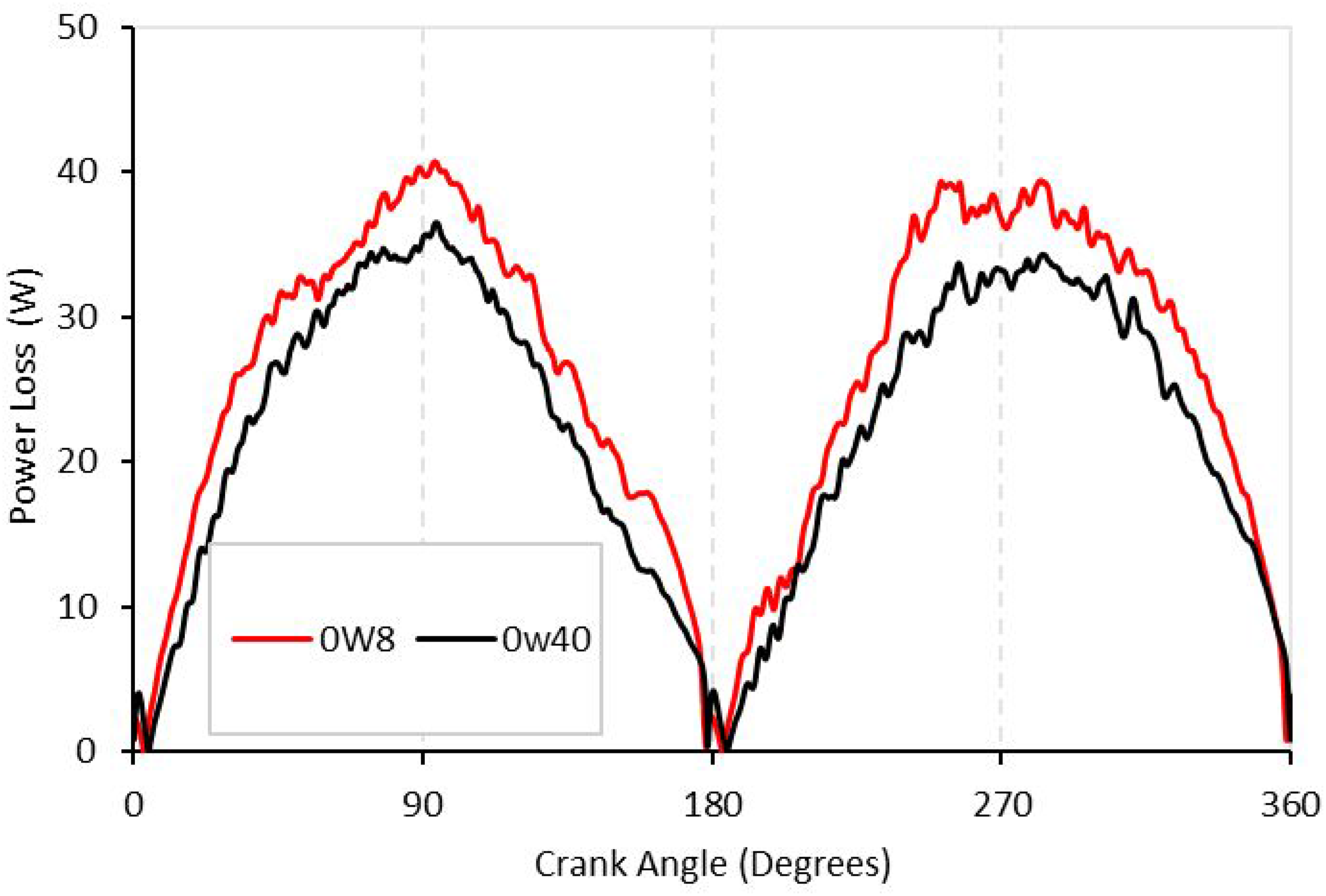
Crank angle resolved friction power losses for 0W8 and 0W40 at 20 °C at 600 rpm.
High temperature friction characteristics
Commonly internal combustion engines are designed to operate within a given temperature window, an elevated temperature of 80°C was considered to be representative of common cylinder liner temperatures and suitable to show the higher operating temperature capability of the test rig. In Figure 10, friction values measured at 80°C are presented throughout the testing range of 300, 600, 900 and 1200 RPM for the 0W40 and 0W8 lubricants. The cycled average friction values are very similar for each of the lubricants due to the reduced difference in viscosity of the lubricant at 80°C.
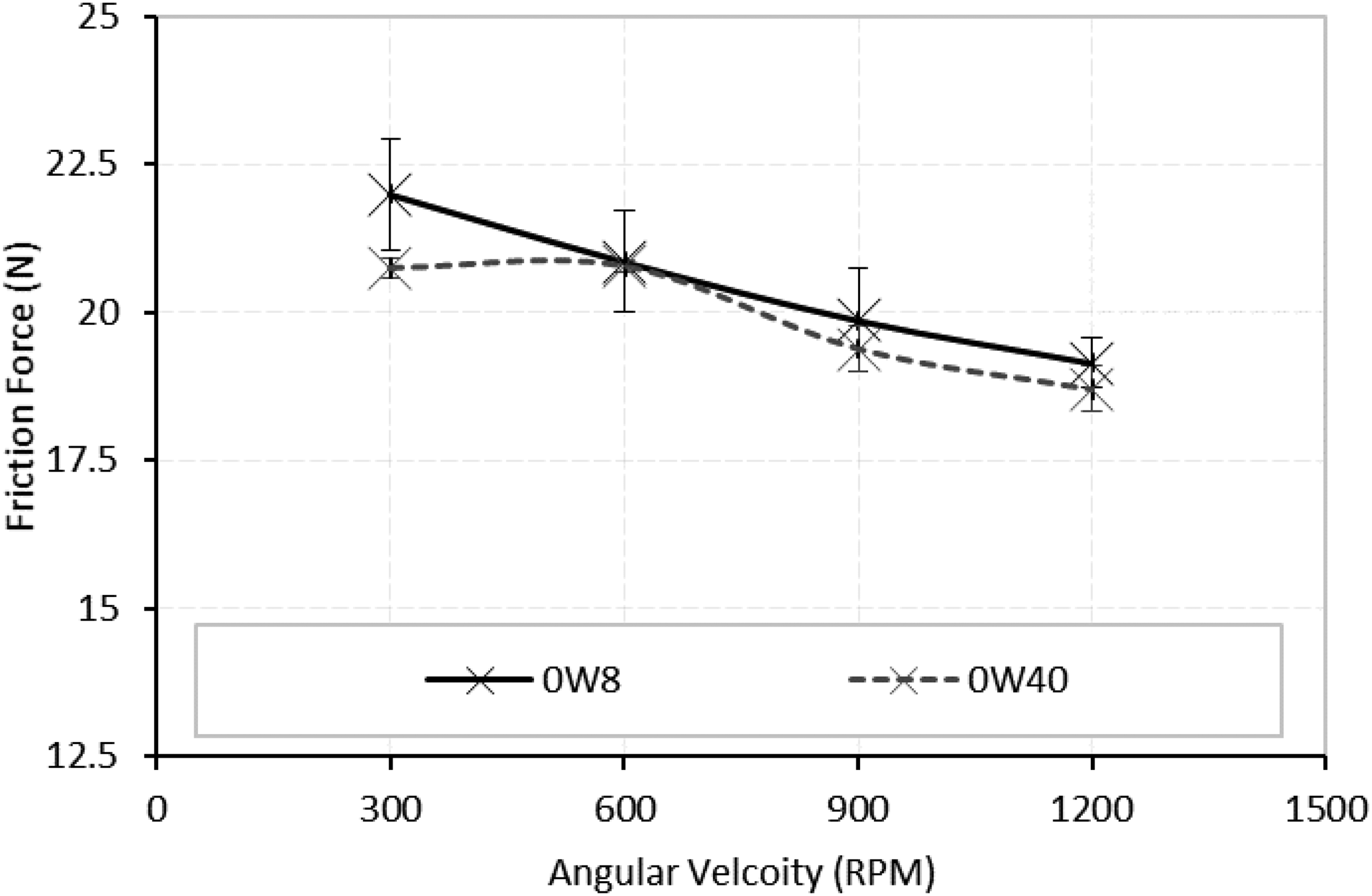
Average three-piece oil control ring-cylinder liner friction measured at 80 °C.
At a temperature of 80°C the average frictional behaviour of the two lubricants becomes very similar. Figure 11(a) and (b) show the similarity in the crank angle resolved friction data at 300 and 900 rpm respectively. This is a result of the reduced viscosity of all oils with temperature but also that at this temperature the viscous properties are much more similar in absolute terms and the difference in viscosity becomes marginal.

Crank angle resolved friction power losses for 0W8 and 0W40 at 80 °C 300 rpm (a) and 900 rpm (b).
Figure 12 shows the frictional losses of a 0W8 lubricant across the speed range at 80 °C. A reduction in mid stroke friction is still shown to take place with increased lubricant entrainment despite the reduced viscosity while the boundary friction at reversal remained similar for all speeds tested.
Crank angle resolved friction power losses for 0W8 and 0W40 at 80 °C across speed range.
Conclusion
A new experimental test rig has been shown to be able to measure the frictional losses of three-piece oil control ring and cylinder liners. The rig is able to successfully measure small friction changes due to oil viscosity in the case demonstrated through two oil grades and also across two temperatures. The experimental results show three-piece oil control rings operate in mixed regime lubrication and any reduction in viscosity serves to only slightly increases frictional losses for this particular conjunction. At a more common operating temperature of 80 °C the frictional losses of each oil are very similar. The new experimental facility and data set are envisaged to be of great use to engine Tribologists and designers who must trade-off the potential power savings from reduced pumping losses and hydrodynamic bearings that low viscosity lubricants can bring with the increase in oil control ring frictional losses presented in this paper, amongst others.
Footnotes
Acknowledgements
The author would gratefully like to acknowledge the assistance and funding provided by the Engineering, Physics and Science Research Council (EPSRC) through the doctoral training partnership.
Declaration of Conflicting Interests
The author(s) declared no potential conflicts of interest with respect to the research, authorship, and/or publication of this article.
Funding
The author(s) disclosed receipt of the following financial support for the research, authorship, and/or publication of this article: This work was supported by the Engineering and Physical Sciences Research Council (grant number Doctoral Training Partnership EP/R513088/1) and Capricorn Automotive Ltd.