
Abstract
One of the pressing challenges facing the German automotive sector nowadays is the time-consuming development process of road vehicles, particularly in comparison to other automotive manufacturers. Traditional approaches, i.e., the sequential design process of road vehicles can lead to tedious data exchange and delayed decision-making. The automation of the development process to reduce development time, while taking into consideration the collaboration between the involved multidisciplinary engineering teams and their tools, can be crucial for the German automotive industry to regain its competitive edge. To address this objective, this paper presents an approach that makes use of the Collaborative Vehicle Configuration Schema (CVeCS) and multidisciplinary design analysis and optimization (MDA(O)) techniques. To be more specific, a unified design process is presented that encompasses the conceptual design phase as well as the initial stages of the subsequent detailed development. The potential of this approach to enhance competitiveness of the German automotive sector is demonstrated based on the MDA(O) workflow of the plug-in hybrid electric vehicle named Interurban Vehicle (IUV). The IUV is a research road vehicle designed at the German Aerospace Center. In general, within the context of this paper, the first steps towards automating the entire development process are taken. Overall, this paper concludes that this approach enables a shift from a sequential development process to a simultaneous one providing a unified, modular and agile design process that contributes to enhancing the decision-making process and facilitating interdisciplinary analyses.
Keywords
Introduction
Problem setting
Over the past few decades, mankind has experienced an exponential technological growth in various fields. As a result, the complexity of products has increased significantly. Road vehicles serve as a good example of such products, whose development typically spans several years. 1 However, in recent years, Chinese automotive manufacturers have successfully reduced the time needed between the initial vehicle concept to start of production (SOP) to a time frame of approximately 24 to 30 months. This reduction provided Chinese manufactures with an advantage compared to, for instance, German automotive manufacturers, who typically require 48 to 50 months from the initial vehicle concept to SOP. 2 The development process consists of different stages/phases. In general, it can be partitioned into three main phases: the conceptual design phase, the detailed development phase and the production. The duration of the development process is influenced by various factors including vehicle classification (e.g., compact cars, luxury cars), technological requirements, regulations and overall complexity. 3 Additionally, development processes have an iterative nature, as developers constantly analyze and adjust their design until the desired function is fulfilled. These adjustments are inevitable and significantly impact the development time and costs of the final product. Leveraging computer-aided engineering (CAE) tools during the development phase allows engineers to conduct virtual analyses and tests, thus reducing the number of physical prototypes and accelerating the development process. Such CAE tools are well established in the automotive industry. However, the multidisciplinary nature of the development process of road vehicles adds another level of complication. Each of the teams involved in the development has its own set of knowledge, CAE tools and data formats. As a result, the automation of the development process, collaboration and data exchange across these teams become a tedious task. This topic is addressed in this paper, as increasing the efficiency of the development process by automating it and enhancing the collaboration and data exchange within the engineering teams can be crucial for the German automotive industry to regain its competitive edge.
State of the art
Product lifecycle management
Within the context of the development process in the automotive industry, product lifecycle management (PLM) systems play a crucial role. They are integrated software applications for managing all product-related data and processes across the entire product lifecycle, from the concept phase through development and manufacturing to operation. PLM systems serve as a central source of information in which technical data, versions, bills of materials and change states are consistently maintained and made available across departments. The use of PLM systems improves the traceability of product changes, increases data consistency, and supports efficient interdisciplinary collaboration. Key benefits include shortened development times, reduced errors caused by version conflicts and enhanced transparency throughout the product lifecycle.
CAE tools in the automotive industry
Within the context of CAE, there exist various tools that are well established in the automotive industry. Computer-aided design (CAD) systems serve as a good example of such CAE tools. 3D CAD models not only define the geometry of the vehicle but also form the foundation for conducting various simulation and validation tasks.4,5 Moreover, digital material modelling and crash simulation are also integral components of the CAE toolset.6,7 Additionally, computational fluid dynamics (CFD) play an essential role in simulating the aerodynamic performance and thermal management of vehicles.8,9 Also, system level simulations, which consider the entire vehicle’s behaviour, such as energy consumption and vehicle performance are considered crucial for the development process, especially in its early phase.10,11 As nowadays, the application of machine learning (ML) is on the rise, it is important to mention its integration in CAE tools. Some simulations, such as crash simulations, require high computational efforts. As a remedy, ML models are being trained on previously conducted simulations to mimic the response of the physics-based simulations. Once provided with the corresponding inputs, the ML models can be executed to generate outputs with significantly reduced computational demand compared to traditional simulation methods.
Automation of the conceptual design phase of road vehicles
Due to the complexity of vehicle concepts, various engineering disciplines are involved in the design process. Each of these disciplines has its own set of knowledge, which is generally encoded in CAE tools. Often, due to the grouping of engineering teams by discipline and/or physical subsystem, the design process occurs sequentially. This sequential designing may lead to infeasible designs. 12 As a remedy, multidisciplinary design analysis (and optimisation) (MDA(O)) techniques can be applied to shift from a sequential to a simultaneous design process. In such simultaneous design processes, CAE tools from different engineering disciplines are fused together into an integrated design process taking into consideration its multidisciplinary nature. Within this context, the authors in Fenyes et al. 13 automated the conceptual design phase by making use of MDA(O) techniques. In addition to business analysis tools, CAE tools from automotive structural design, aerodynamics, fuel consumption analysis and vehicle interior design were integrated into a single design process and executed in the commercial process-integrating software Isight. 14 The exchange of design parameters across the CAE tools involved was orchestrated using a relational data base (MS access) as well as a CAD-Model for geometric parameters. In addition to the conceptual design phase of road vehicles, MDA(O) approaches are also often applied for crash and NVH (noise, vibration and harshness) analysis, see, for instance, the work of Kodiyalam et al. 15 and Duddeck. 16 Inspired by central data models used in the aerospace sector, see, for instance the Common Parametric Aircraft Configuration Schema (CPACS), 17 a central data model for the conceptual design phase of road vehicles, named Collaborative Vehicle Configuration Schema (CVeCS), was introduced in the work presented by Mallah and Alder. 18 The objective of CVeCS is to provide a common language for the domain experts involved in the conceptual design process of road vehicles, thus enhancing the collaboration between them. The applicability of such a central data model was demonstrated based on the MDA workflow of the conceptual design phase of the so called Interurban Vehicle (IUV) (see Section 4.3 in 19 ). Additionally, there exist numerous studies that focus less on the multidisciplinary and collaborative character of the conceptual design phase of road vehicles, while devoting greater attention on automatically generating vehicle concepts. For instance, in the work presented by Prinz, 11 a methodology was provided to create a virtual vehicle concept based on a parametric description of the vehicle’s characteristics. Moreover, Wiedemann 20 provided a software that automates the creation and evaluation of electric vehicle concepts. In the work presented of Münster, 21 a process model was provided. Its main objective is outlining the activities needed to create a vehicle concept and to develop optimized body structures for electric vehicles. Also, a methodology to generate vehicle concepts taking into account autonomous driving was presented by König. 22
Contribution
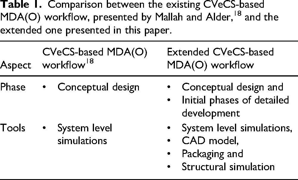
Within the context of enhancing the efficiency of the development process and the competitiveness of the German automotive sector, the primary objective of this paper lies in automating the initial steps of the detailed development phase of road vehicles. More precisely, it aims on establishing a unified design process that encompasses both the conceptual design phase as well as the initial phases of the subsequent detailed development phase. To this end, this paper makes use of the framework presented by Mallah and Alder, 18 which, based on CVeCS, creates a collaborative MDA(O) workflow for the conceptual design phase of road vehicles. However, in the work presented by Mallah and Alder, 18 only the conceptual design phase is considered. To be more specific, only system level analyses and simulations were conducted. For this reason, this paper extends the CVeCS-based MDA(O) workflow to include the initial phases of the subsequent detailed development phase. As a first step to address this objective, a geometric representation of the vehicle concepts is considered. Such geometric models are essential not only to explore the design space of vehicle concepts but also for the subsequent detailed design phase. As a second step, a structural design task related to the vehicle’s body in white (BiW), which is an essential part of the detailed development phase, is taken into account. Table 1 provides a brief comparison between the existing CVeCS-based MDA(O) workflow, presented by Mallah and Alder, 18 and the extended one presented in this paper.
Comparison between the existing CVeCS-based MDA(O) workflow, presented by Mallah and Alder, 18 and the extended one presented in this paper.
This paper is organized as follows:
In Section “Summary of the CVeCS-based MDA(O) workflow” a brief summary of the CVeCS-based MDA(O) workflow presented by Mallah and Alder
18
is provided. Section “Extension of the CVeCS-based MDA(O) workflow” is devoted for the extension of the CVeCS-based MDA(O) workflow to include the initial stages of the detailed development phase. The applicability of the extended CVeCS-based MDA(O) workflow is ensured by demonstrating a use case in Section “Implementation”. Here, the IUV is considered. The IUV is a plug-in hybrid vehicle conceptualized and developed at the German Aerospace Center in Stuttgart, Germany. It is a five-seater road vehicle developed within the context of the Next Generation Car Project to travel comfortably long distances.
23
In Section “Discussion”, the added values as well as the challenges of such an approach are discussed. Finally, Section “Summary and Outlook” is dedicated to summarize the main key points of this paper and to provide an outlook for future work.
Summary of the CVeCS-based MDA(O) workflow
Mallah et al. 19 proposed a framework that aims on automating the conceptual design phase of road vehicles. This is achieved by creating and executing an MDA(O) workflow, to which each of the teams involved in the conceptual design phase contribute with their own set of CAE tools. In the work presented by Mallah and Alder, 18 the central data model CVeCS was introduced and implemented to standardize the interfaces between these CAE tools. In both works the applicability of the MDA workflow and CVeCS were evaluated by using the conceptual design phase of the IUV as a case study.
CAE tools
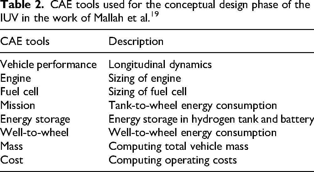
The CAE tools considered for the conceptual design phase are system level simulations having a run time of few seconds. These are listed in Table 2. For further details, see Section 4.4 in the work of Mallah et al. 19
CAE tools used for the conceptual design phase of the IUV in the work of Mallah et al. 19
CVeCS
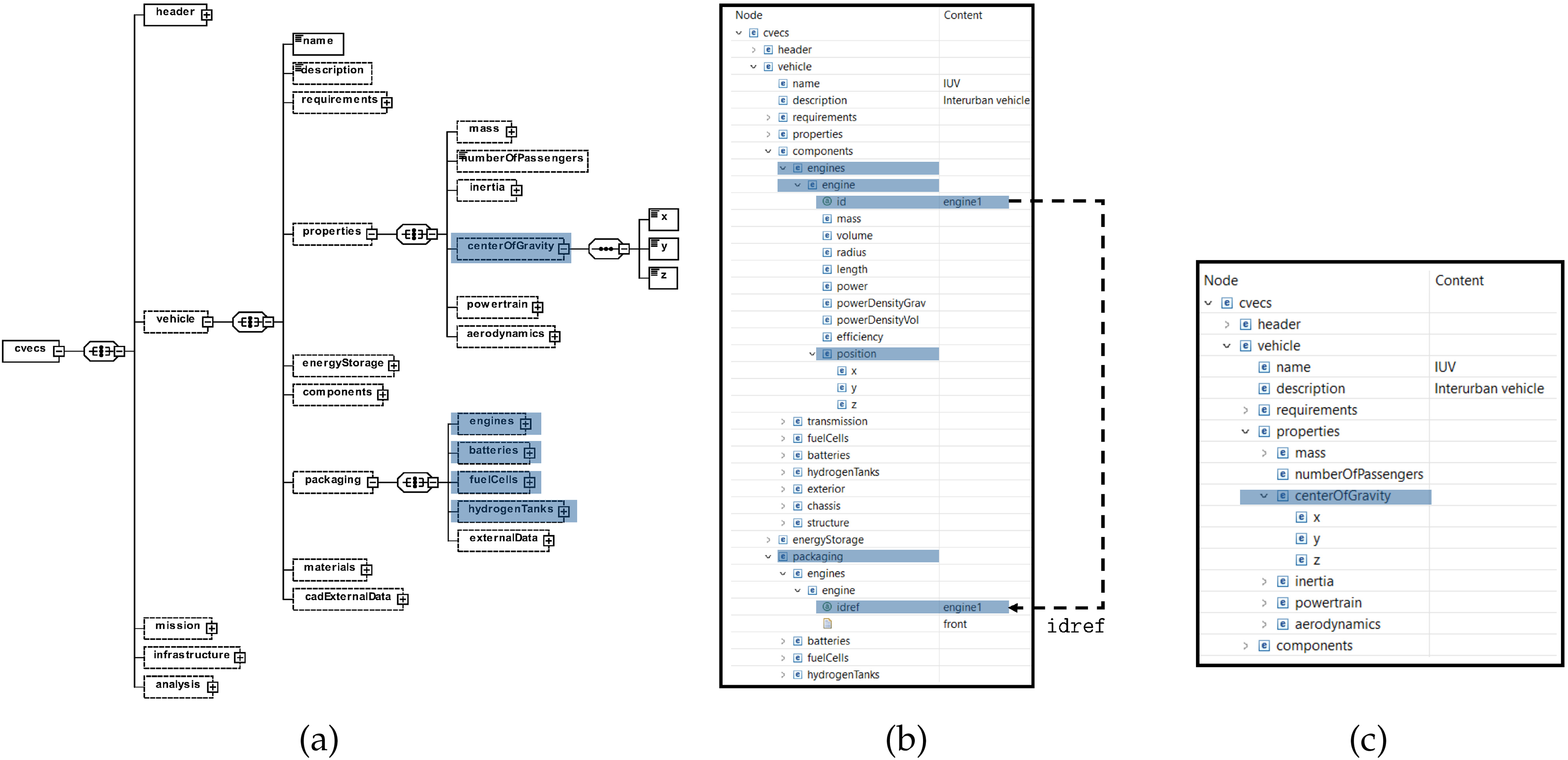
CVeCS was introduced in the work presented by Mallah and Alder. 18 It is a central data model with the objective of improving the collaboration within the multidisciplinary design process of road vehicles. CVeCS orchestrates the data exchange across the disciplines involved in a central manner, thus standardizing the interfaces and reducing the number of interactions between them. It is designed as an XML schema definition (XSD) for use with XML (XML stands for extensible markup language). 24 As a result of the hierarchical structure of XML, CVeCS can parameterize the different vehicle systems and their corresponding subsystems and components, as seen in Figure 1. Mallah and Alder 18 derived the IUV’s XML file based on CVeCS. For instance, the CAE tool Engine, listed in Table 2, is a Python tool that computes the engine’s power, mass, volume and dimensions needed to fulfill the IUV’s performance requirements (see Figure 2(a)). For this purpose, the engine tool requires the inputs: maximum power demand, continuous power demand as well as the gravimetric and volumetric power energy densities of the engine. This parameter exchange between the engine tool and the XML file is illustrated in Figure 2(b).
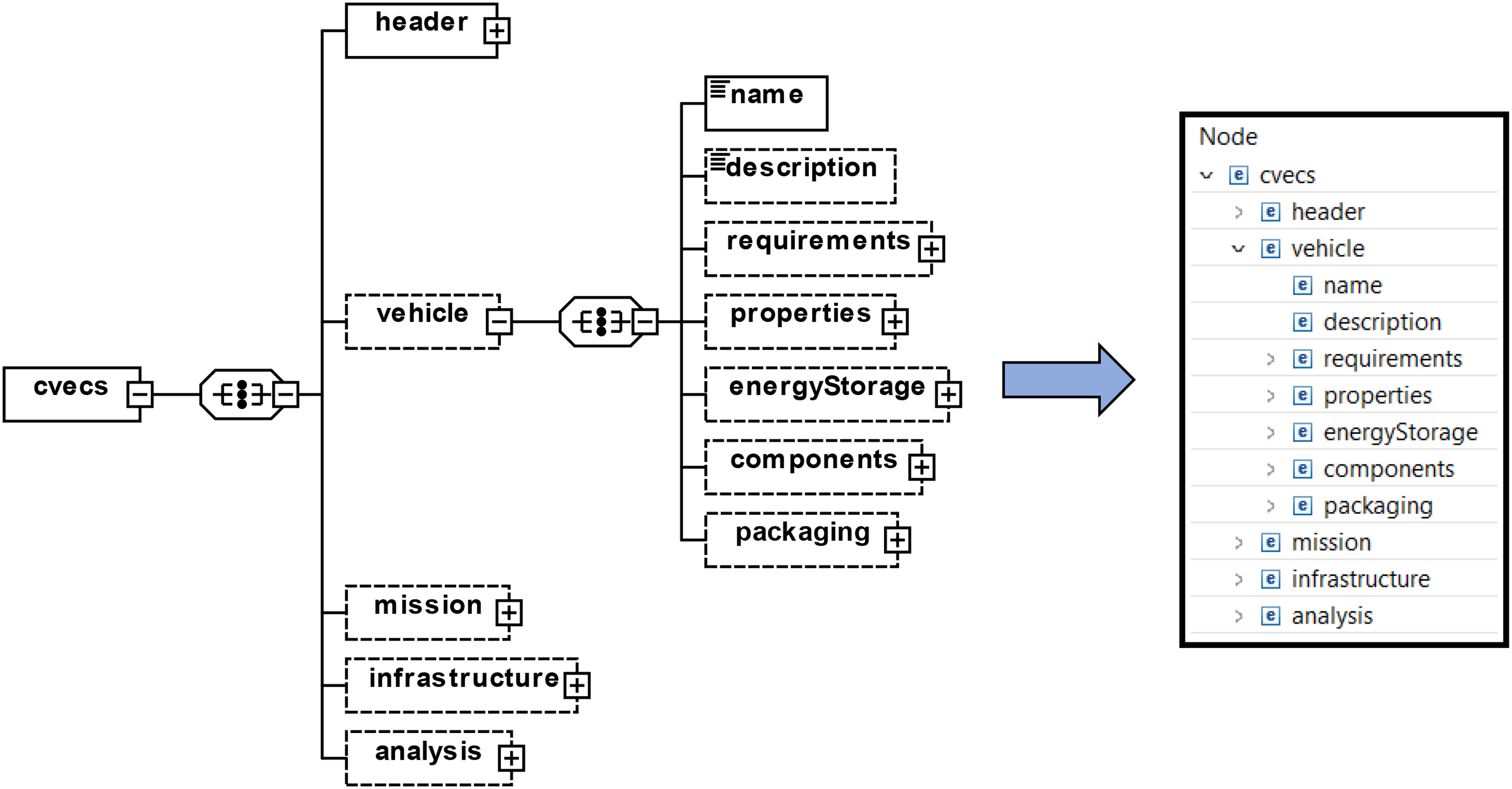
XSD diagram of CVeCS (left); XML file derived based on CVeCS (right). 18
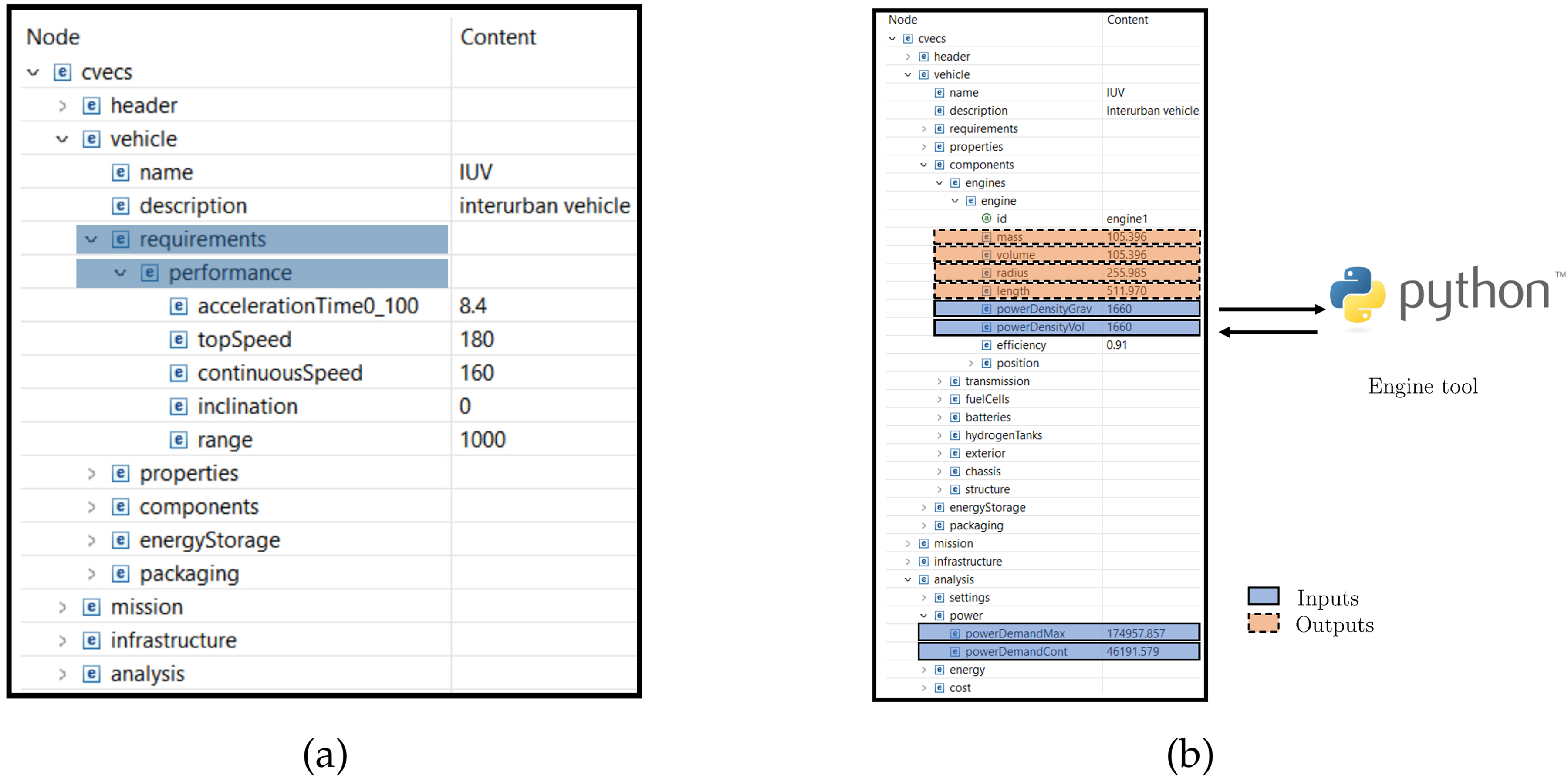
(a) Parametrization of the IUV’s performance requirements; (b) Exchange of parameters between XML file and engine tool. Python logo in Figure 2(b) is used according to Python Software Foundation (PSF) trademark guidelines.
MDA
Based on the IUV’s XML file illustrated in Figure 2 and the CAE tools listed in Table 2, an MDA workflow for the conceptual design phase was schematically modeled in MDAx (Multidisciplinary Design Analysis and Optimization Workflow Design Accelerator). 25 In MDAx, the MDA(O) workflow is modeled but not executed. Here, domain-specific CAE tools can be schematically created. One of the significant advantages of MDAx is that it supports the integration of XML-based data models, such as CVeCS. To be more specific, the XML file, derived from CVeCS, is uploaded to MDAx allowing the users to assign the input and output parameters to the corresponding CAE tools. The XML file serves as an input and output file for all the CAE tools involved in the design workflow. Therefore, the communication between the domain-specific tools involved is standardized. This interplay between the design workflow and the XML file is illustrated in Figure 3. On the diagonal of the MDA workflow (XDSM:(XDSM stands for extended design structure matrix. 32 ) right image in Figure 3), the CAE tools are schematically represented using rectangular boxes. The rounded rectangle represents a converger, which checks for the convergence of the vehicle’s curb weight. More precisely, since several CAE tools used require the vehicle’s curb weight as an input, an initial value is set. After computing the curb weight using the CAE tool Mass (see Table 2), a convergence check is performed between the initial value and the computed one. If the convergence criteria is not met, a new iteration of the MDA workflow is executed. This ensures that a consistent vehicle concept is generated. The execution of the MDA workflow takes place in the open-source process integration software Remote Component Environment (RCE) in an automated manner. 26 I.e., the MDA wokflow is exported from MDAx to RCE. During the execution, each CAE tool hosted on its respective server is invoked and the necessary data is exchanged. 26
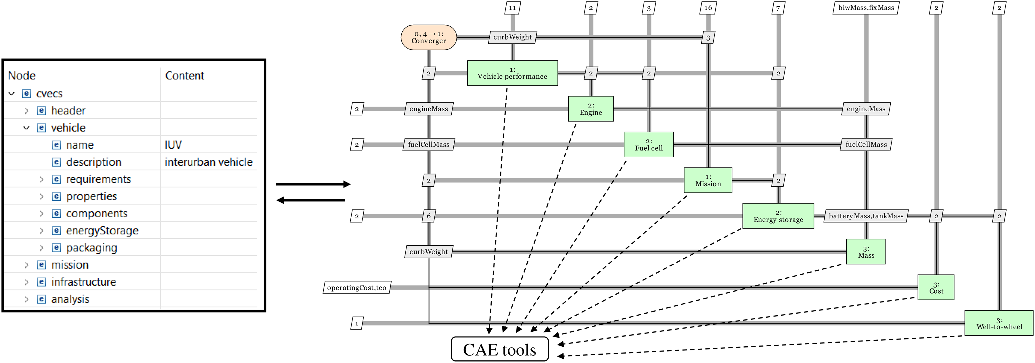
Schematic illustration of the interplay between the IUV’s XML file and the MDA workflow.
Steps to create a CVeCS-based MDA(O) workflow for the conceptual design phase
Mallah and Alder
18
generalized the process of creating a CVeCS-based MDA(O) workflow by listing the following steps:
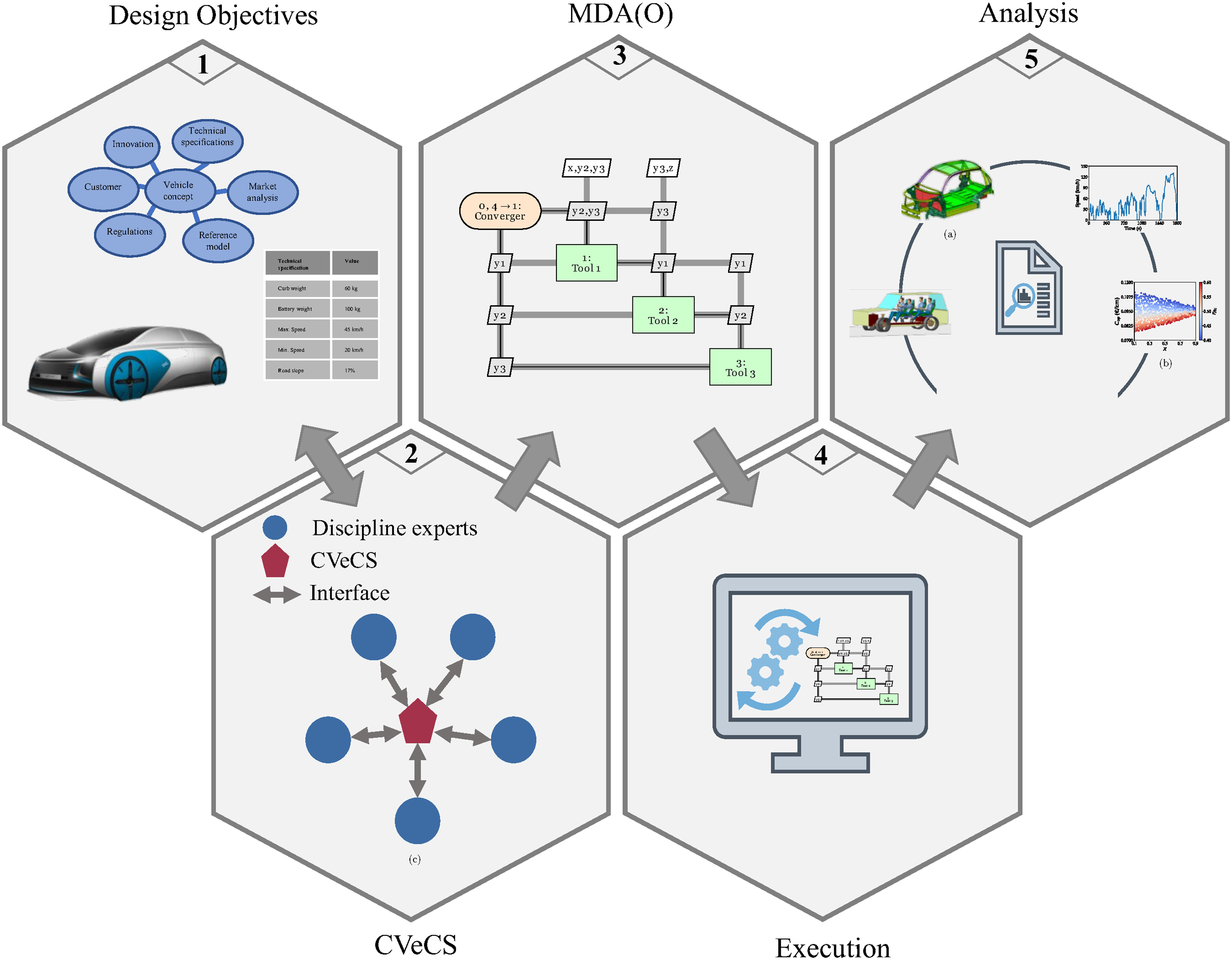
Establishing the design goals: Here, the designers define the objectives of the vehicle concept to be created, i.e., the transport task, intended operating environment, etc. Based on these objectives, the parameters and the domain-specific CAE tools are established. If the existing XSD (CVeCS) contains all the required parameters, an XML file can be derived from it; otherwise, the XSD must be extended before generating the XML file. Developing the tools’ interfaces to the CVeCS-based XML file: Here, the interfaces between the CAE tools and the XML file are standardized by creating a wrapper for each tool. This wrapper reads the inputs from the XML file and writes the outputs back to the XML file. Creating the MDA(O) workflow: The CAE tools are fused together and the input and output parameters are assigned to their respective tool, for instance by using MDAx.
25
Executing the MDA(O) workflow: The MDA(O) workflow is executed in a process integration software, such as RCE.
26
Processing and analyzing the results: After executing the MDA(O) workflow, the outputs are processed and analyzed.
These steps are schematically illustrated in Figure 4.
Impact of the CVeCS-based MDA(O) workflow on the efficiency of the conceptual design phase
In the aeronautical engineering sector, the use of such XML-based data models in combination with MDA(O) workflows in a multidisciplinary design process has been validated in practice. For instance, in the work presented by Ciampa and Nagel,
27
a lead time reduction by up to
Extension of the CVeCS-based MDA(O) workflow
Geometric representations are essential for the development process of road vehicles. For this reason, the framework provided by Mallah et al.
19
and Mallah and Alder,
18
i.e., CVeCS and the MDA workflow, is extended to include a parameterized geometric/CAD model of vehicle concepts. Such a CAD model:
allows designers to conduct various packaging analyses exploring the design space of vehicle concepts and serves as a starting point for the subsequent detailed design phase, where the vehicle concept is refined by conducting detailed simulations and validation tasks.
Parametric CAD model
The CAD model is parameterized and can be freely configured. It focuses solely on the main dimensions of the vehicle’s exterior as well as on a highly simplified interior with different manikins. The manikins can be arranged in different seating configurations. This includes the number of rows and seats per row as well as the posture of the manikins. In addition, the vehicle’s technical components can be sized and positioned depending on the desired drive train configuration. It is also possible to configure different wheelbases, track widths and wheel dimensions with their envelope curves. Legal requirements, such as for the positioning of headlights, direction indicators and rear lights, are also implemented in the model. Using this model, different vehicle configurations can be generated and visualized in a simplified and a rapid manner (see Figure 5).
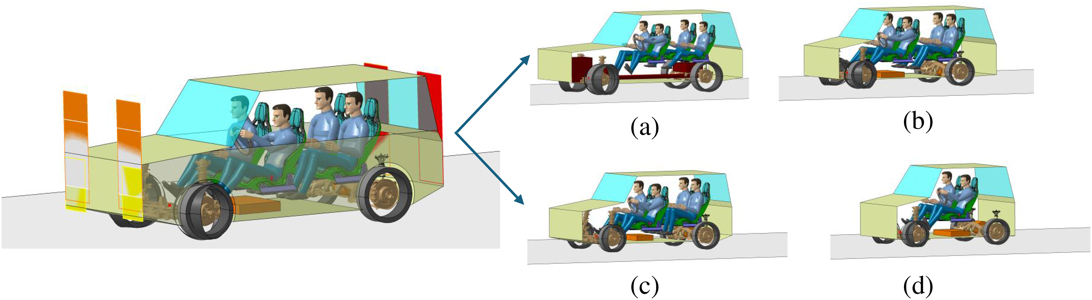
Parameterized CAD model of a reduced vehicle: (a) Sport utility vehicle (SUV) with combustion engine and four occupants; (b) Battery electric compact vehicle for four occupants; (c) Battery electric small vehicle for four occupants; (d) Battery electric small vehicle for two occupants.
Interface between CVeCS and the parametric CAD model
The CAD model is not controlled in a classical, iterative, manual manner, but is rather completely parameterized. The entire CAD model is based on a large number of parameters that define the geometric and functional properties of the components and assemblies. Many of these parameters are logically dependent on each other, such that changes to one parameter automatically trigger consistent adjustments in dependent areas of the model. These parameters are managed centrally via CVeCS, which serves as a higher-level control system. CVeCS ensures that all relevant design information is uniformly structured and available for the CAD environment. Communication between CVeCS and the CAD system takes place via a standardized interface. More precisely, data is exchanged using an interface table in Microsoft Excel, which acts as a bridge between CVeCS and the CAD system. As soon as parameters are varied in CVeCS, they are directly transferred to the CAD system via the interface table. This data exchange between CVeCS and the transfer table is automated using Python. Additionally, the current configuration of the model is visualized directly in CAD without the need for manual adjustments. This approach creates a high degree of automation and traceability in the design process. Model changes can be implemented consistently and in a reproducible manner. This significantly reduces the effort involved in developing variants of the CAD model. In addition, data integrity between the CAD system and CVeCS is maintained, minimizing sources of error and shortening the time needed for development. Based on this parameterized CAD model, tools are developed to:
visualize various packaging scenarios in the conceptual design phase in an automated manner and integrate and automate the first stages of the detailed development phase, i.e., BiW development.
Packaging
In general, packaging is an essential part of a vehicle concept. In the work presented by Braess and Seifert, 28 packaging is defined as the positioning and arrangement of the main vehicle components, such as energy storage components, transmission and passenger compartment. Taking into consideration geometrical and physical aspects is crucial for packaging. Avoiding collisions between components, vehicle dynamics and passengers’ safety serve as a good example of such aspects. Due to the importance of packaging in the conceptual design phase of road vehicles, a simple packaging tool is added to the MDA workflow.
Packaging tool
The packaging tool was developed with simplicity in mind and can be extended in future work. Its objective is to determine the positions of the vehicle components and accordingly the vehicle’s center of gravity. The tool was developed under the following assumptions:
Only the drive components of the vehicle, i.e., engines, batteries, fuel cells and hydrogen tanks are considered. The position of the vehicle components is determined by the Some fixed packaging configurations are predefined. These packaging configurations are compared with the user’s input. If the user’s input configuration matches one of the predefined configurations, the user’s configuration is implemented; otherwise an error is raised. The packaging configuration is defined using: (i) the name/id of the vehicle components and (ii) a string defining their position. For instance, the packaging configuration of the first engine with an engine id
Extension of CVeCS to include packaging
In CVeCS, the input packaging configuration is structured under the 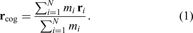
(a) CVeCS’s XSD diagram: extension of the
Side sill designing
After creating a vehicle concept or several vehicle concepts based on the defined requirements, the development of the vehicle’s BiW is carried out. 21 The main objective of the BiW is to support all vehicle’s components (e.g. engine, seats, dampers) and to withstand loads (e.g. crash, bending, torsion) acting on the vehicle. 29 To fulfill this objective, the BiW in turn, consists of several components, each serving a specific role. Within the context of this paper, one component of the BiW is taken into consideration, namely the side sill, which is typically manufactured using the extrusion process. The side sill plays a crucial role in absorbing side impacts of road vehicles, especially electric or hybrid road vehicles, where battery pack or hydrogen tanks may be placed at the bottom of the vehicle along the floor pan. 21
Geometric modeling of side sill in CAD system
For simplicity reasons, the cross-section of the side sill is modeled as a rectangular profile reinforced by a variable number of webs in vertical and horizontal direction. These webs contribute both to increasing the structural stiffness and to optimizing the use of materials. In the CAD system, the side sill profile is modeled using mid-surfaces to ensure easy integration into a later simulation model. As part of the parameterized design, key features of the side sill can be freely configured. Both the position of the side sill within the assembly and its geometric dimensions (length, width, height) can be variably adapted. Additionally, the number of the inner webs can be varied as required. Figure 7 illustrates the design methodology of the side sill. It can be seen that all vertical and horizontal elements of the side sill can each be traced back to two reference mid-surfaces that are aligned horizontally and vertically. These two reference mid-surfaces are located in the top left-hand corner of the side sill’s cross-section and form the starting point for the modeling. Initially, these reference mid-surfaces were modelled parametrically such that their position and dimensions are directly dependent on the higher-level parameters of the side sill. Such higher-level parameters include the overall position of the sill, the dimensions (length, width and height) and the number of webs in horizontal and vertical direction. These dependencies ensure that changes to the global parameters have a direct effect on the geometry of the reference mid-surfaces, thus ensuring consistent adaptation of the entire model. Using a pattern operator, the two reference mid-surfaces are duplicated in horizontal and vertical direction according to the specified higher-level parameters. In this manner, the entire geometry of the side sill is mapped automatically and adapted parametrically.
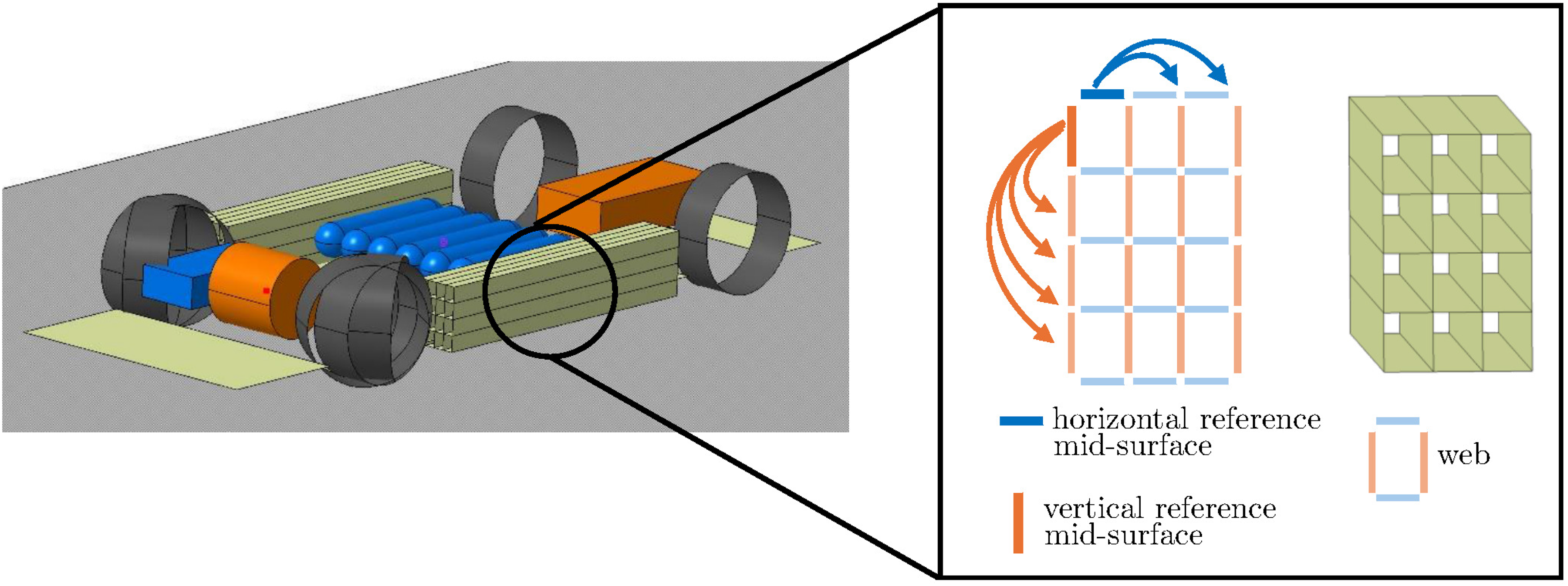
Geometric modeling of side sill.
Extension of CVeCS to include the geometric modeling of side sill
In CVeCS, the BiW node is extended to include the vehicle’s side sill (see Figure 8(a)). I.e., the parameters relevant to the geometric modeling of the side sill are structured under
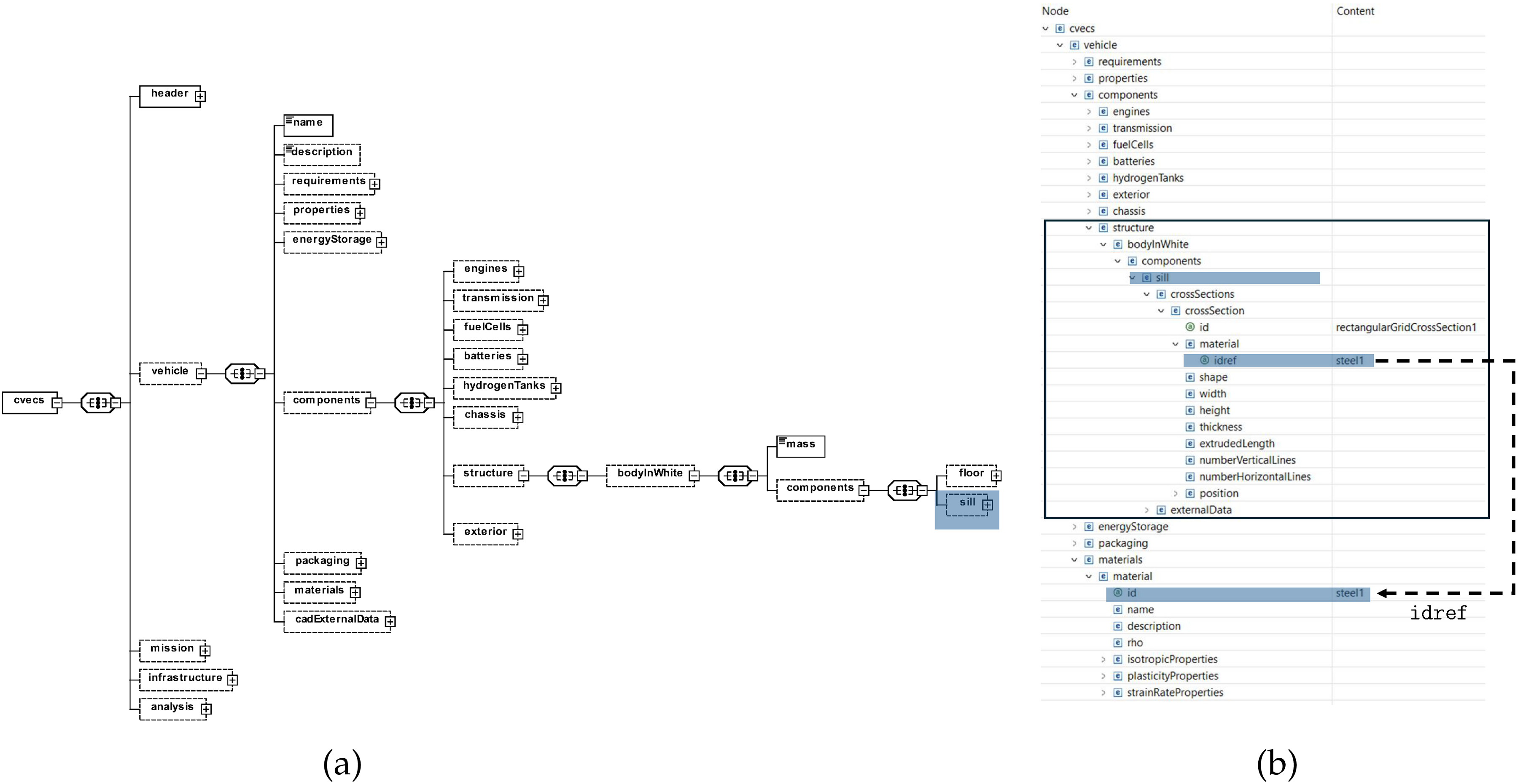
(a) CVeCS’s XSD diagram: extension of the
Side sill crash tool
Once the side sill is geometrically modeled, it is saved as a separate step file, and the parametric CAD model is then updated to include the side sill. Subsequently, the step file of the side sill is used as an input to the crash simulation. Here, the Euro NCAP’s test
30
for lateral impact serves as a basis for the development of the side sill crash simulation/tool. In this test, the vehicle is propelled laterally at a speed of Only the side sill is taken into consideration and not the entire vehicle. The side impact is modelled as a three-point bending test (see Figure 9), where the side sill is placed on two parallel rigid supports while a pole applies a force to the center of the side sill. Here, the pole is assigned a speed of Theoretically, in the three-point bending simulation, the kinetic energy of the pole To ensure that the side sill is absorbing the same amount of energy in the three-point bending simulation To model the friction between the rigid supports, the side sill and the pole, the Coulomb friction model is taken into account. I.e., the friction force does not depend on the magnitude of the velocity.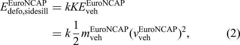
For this purpose, an explicit finite element analysis (FEA) is conducted. The total simulation time is set to 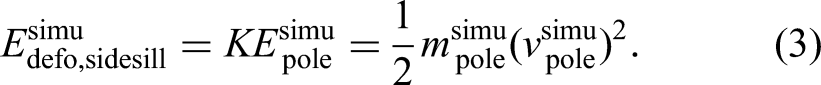


(a) Side sill’s simulation model for lateral crash test; (b) Deformation of side sill during lateral crash.
Extension of CVeCS to include the crash simulation of the side sill
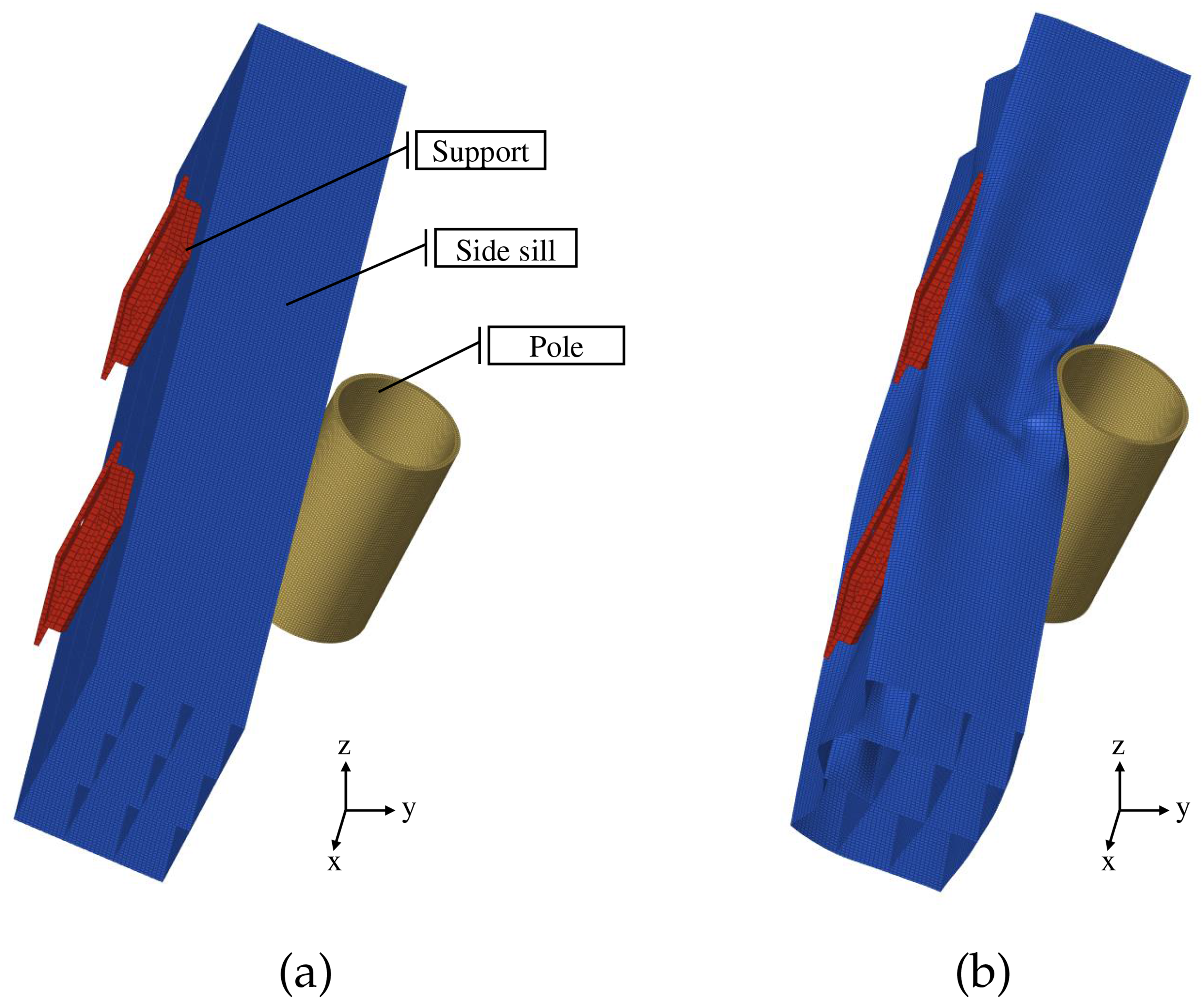
The material model used for the crash simulation is crucial, as it dictates the material’s behaviour during the simulation. For this reason, CVeCS is extended to include parametric description of materials that are used in the design process. Each material is defined under the its density its isotropic properties its plasticity properties parameters related to the dependency of a material’s behaviour on strain rate
In the current implementation of the plasticity properties, the hardening curve describing the relation between the yield stress
(a) CVeCS’s XSD diagram: including
Implementation
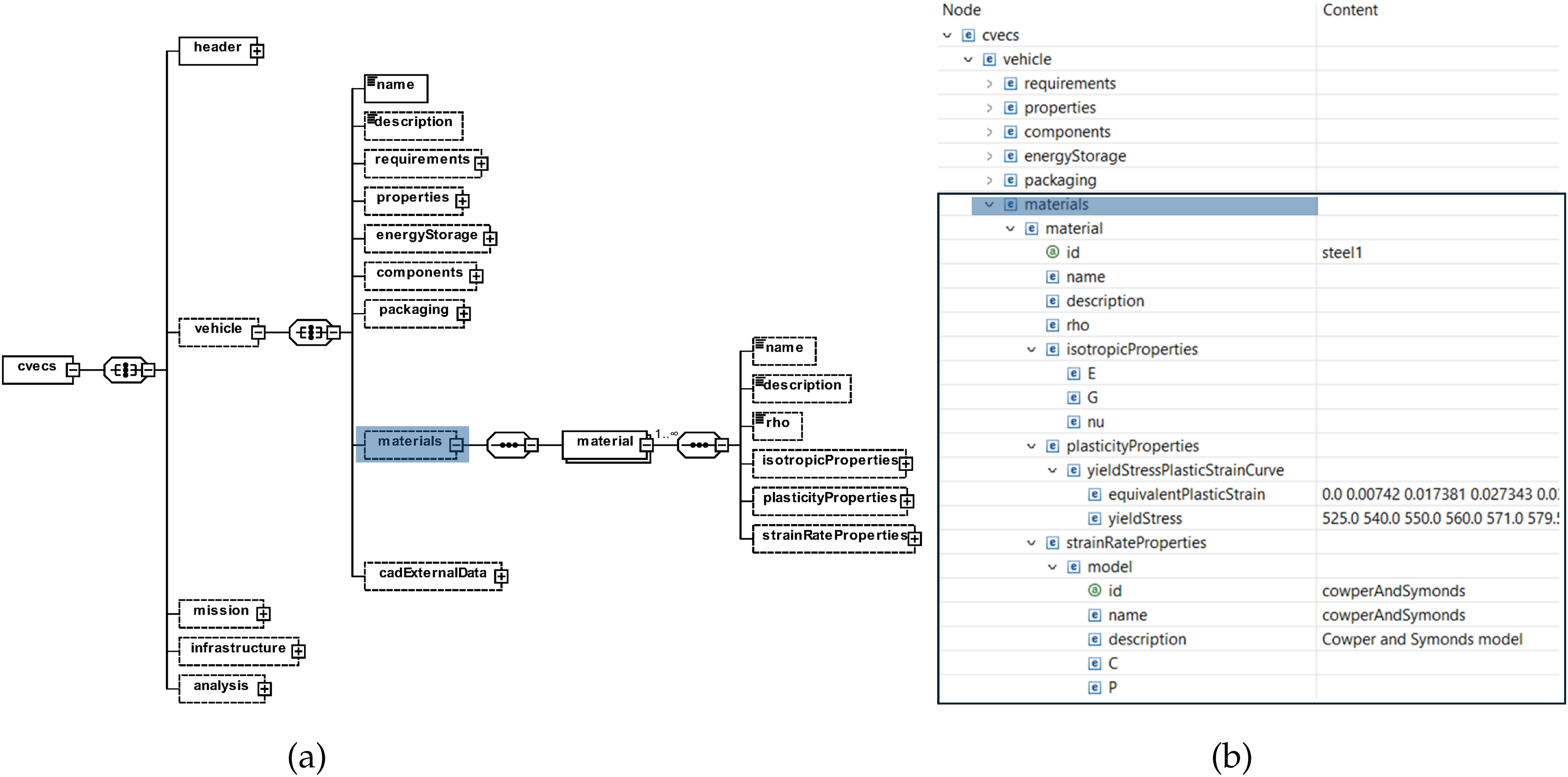
To demonstrate its applicability, the extended CVeCS-based MDA(O) workflow is implemented to the IUV, which is a plug-in hybrid vehicle consisting of a rechargeable battery pack, a fuel cell and hydrogen tanks. Within the scope of this simple use case, the extended CVeCS is used to derive the XML file structuring the IUV’s parameters. Additionally, the extensions of the MDA(O) workflow, i.e., packaging tool, parametric CAD model and side sill designing tools (see Table 3) are applied to the IUV’s MDA.
CAE tools used for the conceptual design phase of the IUV in the work of Mallah et al. 19 and the added CAE tools in this paper.
Design task
Two of the key criteria considered when designing road vehicles are performance and safety. For this reason, in this use case, the effect of some performance parameters on some structural parameters, which directly affect safety, is investigated. More precisely, the effect of the required driving range on the distance between the IUV’s side sill and the hydrogen tanks is examined. In the IUV’s packaging configuration, the hydrogen tanks are positioned at the bottom of the vehicle along the floor pan (see Figure 14). To ensure the safety of the hydrogen tanks, the distance between the side sill and the hydrogen tanks should be large enough to avoid collisions as well as impacts during lateral crash. To distinguish between collision and impact, the terms pre-impact distance and post-impact distance are used, respectively.
Design of experiment
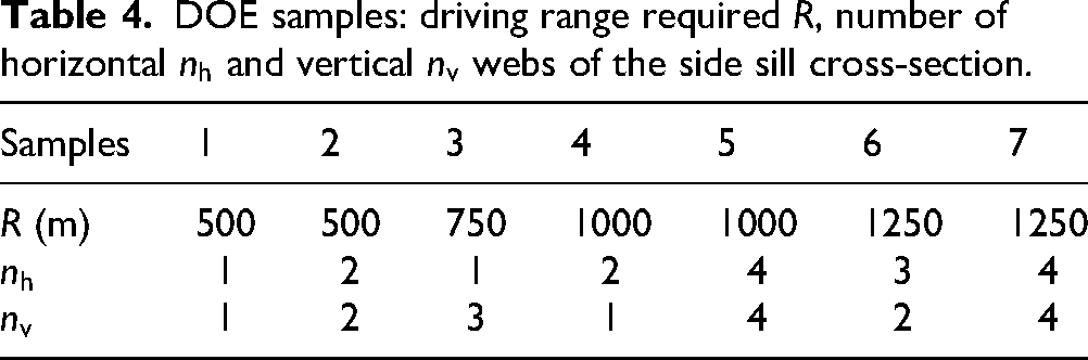
For the purpose of this simple use case, a Design of Experiment (DOE) study is considered, where some performance as well as structural parameters are varied. For the performance criterion, the driving range required
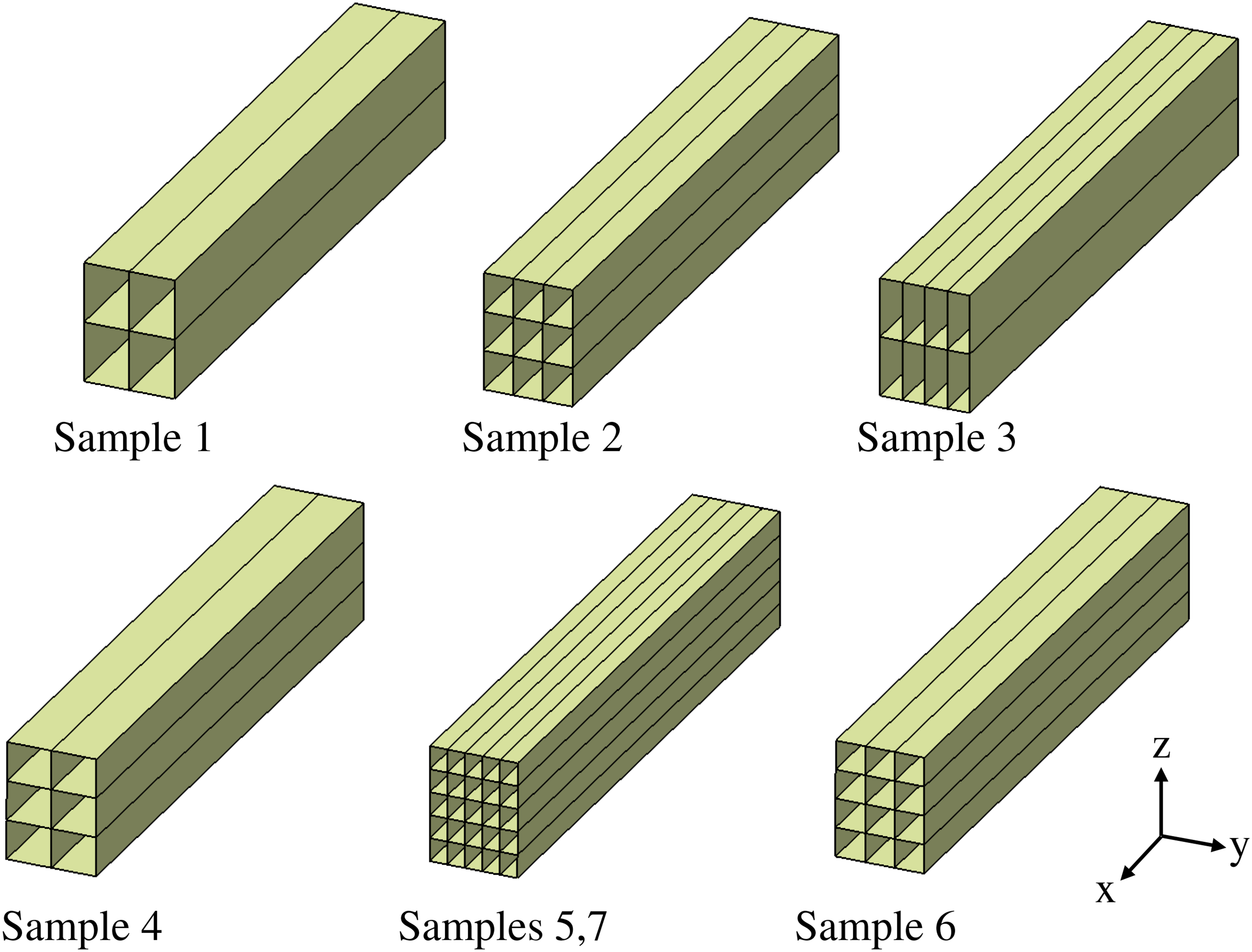
CAD model of the sampled side sills generated in an automated manner.
DOE samples: driving range required
The outputs examined are the vehicle’s curb weight
Assumptions
Here, the following assumptions are taken into account:
The packaging configuration of the IUV is fixed. I.e., the hydrogen tanks are positioned at the bottom of the vehicle along the floor pan. All hydrogen tanks have identical dimensions. The mass of the side sill is not considered for the computation of the vehicle’s curb weight. The position of the side sill is held constant. The width and height of the side sill cross-section are fixed. The side sill’s length is held constant.
Setup
As in Figure 4 illustrated, the first step within the CVeCS-based MDA(O) workflow is to choose the CAE tools based on the design task considered. The CAE tools considered for this use case are summarized in Table 3. As a second step, the XML file, which serves as a single input and output file for the CAE tools, is derived from the extended CVeCS. Additionally, the interfaces of the CAE tools to the derived XML file are prepared. Third, the MDA(O) workflow is modeled in MDAx 25 and subsequently executed in RCE in an automated manner. 26 For further information regarding MDAx and RCE see Section “Summary of the CVeCS-based MDA(O) workflow”.
Results
The extended MDA workflow of the IUV used in this use case is illustrated in Figure 12. Here, the rounded rectangle represents the DOE driver. In Figure 13, the variation of 
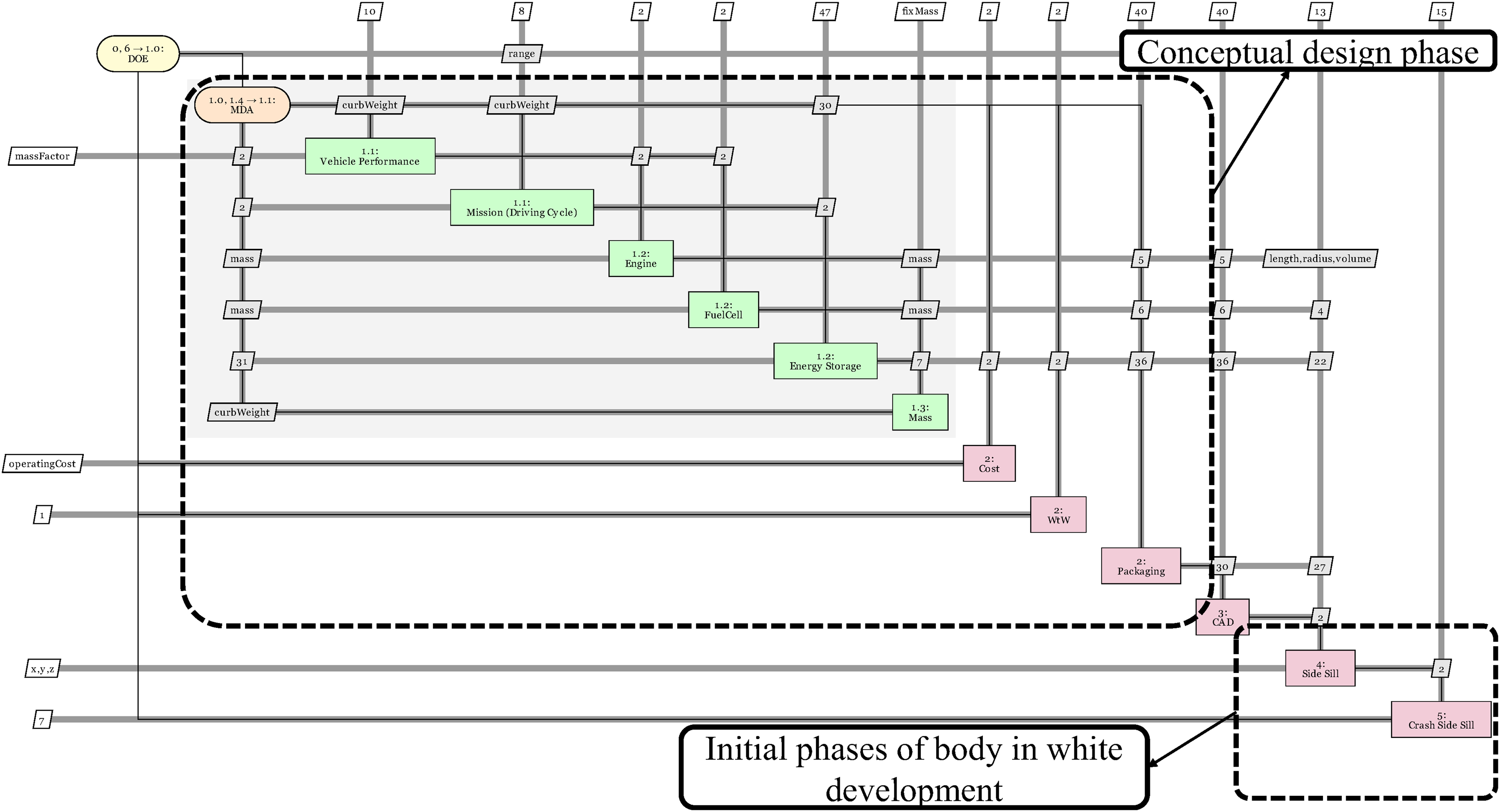
Extension of the IUV’s MDA workflow to include a parametric CAD model and the initial phases of the body in white development.
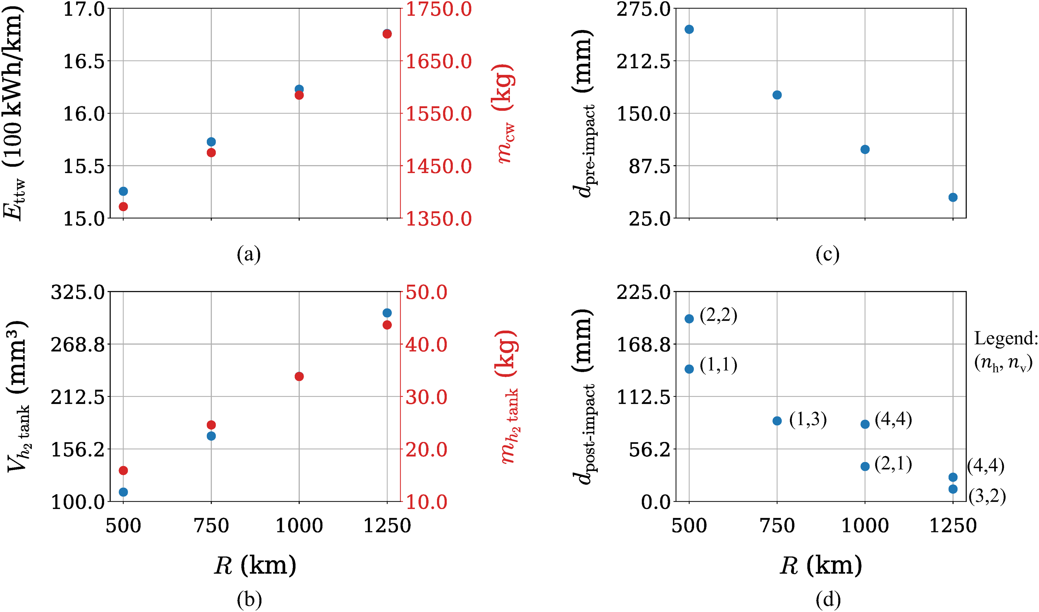
The variation of
Examining Figure 13(d), two trends can be identified. First, as
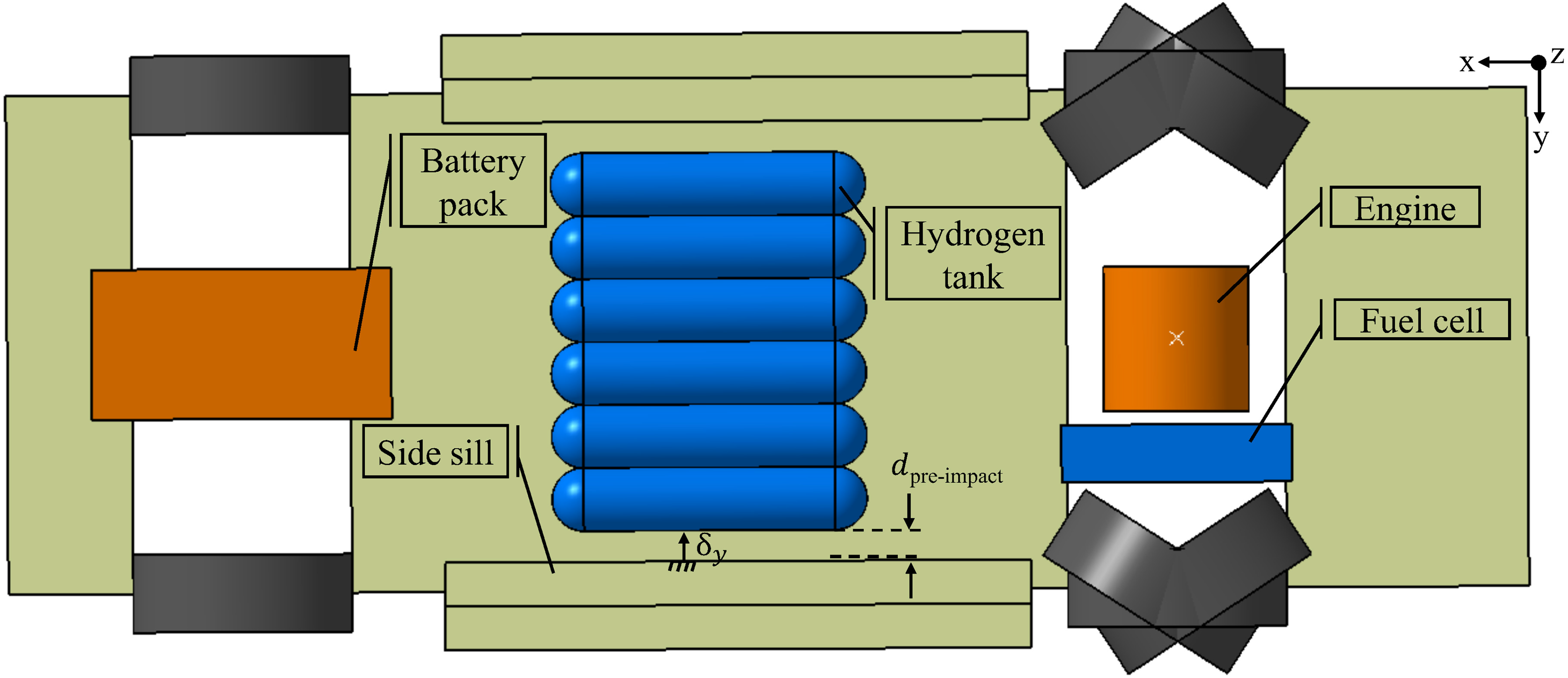
CAD model illustrating the battery pack, side sill, hydrogen tanks, engine, fuel cell,
Discussion
Added value
Despite it’s simplicity, the use case presented in Section “Implementation” provides a proof of concept that demonstrates the added value of the CVeCS-based MDA(O) workflow (see Section “Summary of the CVeCS-based MDA(O) workflow” for a brief summary) in the conceptual design phase as well as the subsequent detailed development phase of road vehicles. As Mallah and Alder 18 discussed, the CVeCS-based MDA(O) workflow provides a centralized design process. In one respect, the design parameters are consolidated into one single file derived from CVeCS, to which all designers have access. This reduces the number of interactions between the involved disciplines. In another respect, the MDA(O) workflow provides a unified and modular design process for all involved disciplines. Here, discipline experts can add, remove and modify their domain-specific tools, which enhances flexibility and adaptability within the design process. Moreover, by conducting a Design of Experiments (DoE) study involving parameters from several disciplines (see Section “Implementation”), it was demonstrated that having a unified design process for the involved engineering disciplines, facilitates conducting interdisciplinary studies.
Comparison to a sequential, non-unified, non-automated design process: The detailed development phase of road vehicles is a complex process involving many steps and iterations. For this reason, digitizing and automating such a process is a tedious task. Extending the CVeCS-based MDA(O) workflow in this paper served as a first step towards this goal. Here, including a parametric CAD model that generates a geometric representation of the vehicle concepts in an automated manner was essential. By linking the CAD model to the vehicle’s parameters, computations, i.e., CAE tools, were easily integrated with the CAD model. As a result, changes in the vehicle’s characteristics quantified by these parameters, were directly translated to the geometric representation of the vehicle concept. In the use case presented in Section “Implementation”, the performance requirements as well as structural parameters were varied. This allowed designers to explore different scenarios in an automated manner, which can enhance the decision-making process. If this process were not automated, the changes in the performance requirements, i.e., range as well as in the structural parameters, i.e., number of vertical and horizontal webs of the side sill’s cross-section, would have involved iterative contributions from at least four engineering domains. These domains include: (i) energy management, to examine the effect, the change in range have on the energy consumption, (ii) sizing of the drive components due to the effect, the change in energy consumption has on the dimensions of the drive components, (iii) designing of the side sill due to the effect, the webs of the cross-section have on the side intrusion during a lateral crash, which is restricted due to the dimensions of the drive components and iv) CAD designing to implement the changes in the drive components’ dimensions and side sill’s cross-section to the vehicle’s geometry. Having a central data model (CVeCS), a unified design process and a parametric CAD model enabled each of these discipline experts to conduct such an interdisciplinary analysis in an automated manner (without manual intervention) and independent from the other disciplines. In contrast, having a sequential, non-unified design process, such interdisciplinary studies can not be conducted simultaneously. As a result, each iteration involves direct coordination between the participating teams, thus increasing the time needed for the design process. This is particularly true, when considering sensitivity analysis and optimization of the whole design. Such interdisciplinary tasks further emphasise the efficiency benefits of the CVeCS-based MDA(O) workflow in comparison to a sequential, non-unified design process. For this reason, future work will focus on examining sensitivity analysis and optimization within the context of the CVeCS-based MDA(O) workflow.
Transferability: Additionally, it is worth noting that the CVeCS-based MDA(O) workflow is not limited to the IUV use case, presented in Section “Implementation”. Rather, it offers a generic design methodology with broad applicability. The application is dictated by the design objectives considered, which in turn determine the most suitable CAE tools for these objectives. If CVeCS and the parametric CAD model already cover the needed parametric descriptions, they can be utilized directly. Otherwise, they may need to be modified and/or extended. The modular nature of the MDA(O) workflow facilitates the addition and/or substitution of CAE tools. For instance, if the design objectives were to develop a fuel cell plug-in hybrid urban vehicle instead of the IUV, the IUV use case can be applied with minimal modifications. These modifications are limited to the parameter values used. However, if the objective of the BiW development also includes designing, for instance, the vehicle’s B-pillar, CVeCS and the parametric CAD model need to be extended to include the parameterization of the B-pillar. In addition, the corresponding CAE tools for the B-pillar are to be added to the MDA(O) workflow. For this purpose, future work will address the extension of the CVeCS-based MDA(O) workflow to cover the parameterization of a larger number of vehicle components.
Comparison to PLM: The CVeCS-based approach offers significant advantages, particularly when compared to traditional PLM environments in the conceptual design phase of road vehicles. While PLM systems primarily focus on data management, version control and process governance, CVeCS provides a parametric central data model that is explicitly designed for the automated and flexible coupling of multidisciplinary CAE tools. This enables a consistent link between design parameters, CAD geometry and simulation-based analyses. Changes in requirements or boundary conditions are automatically propagated throughout the entire MDA(O) workflow, allowing rapid variant generation. CVeCS also complements PLM systems with an agile, model-driven integration layer that significantly accelerates the transition from conceptual design to initial detailed development.
Challenges
One of the biggest challenges within the context of the CVeCS-based MDA(O) workflow is involving domain experts from various engineering disciplines. Each of these disciplines has built its own knowledge and tools over the years. As a result, this requires constant effort to ensure that they adhere to consistent and unified guidelines to build a unified design process. 18 Within this context, the involved engineering disciplines must agree on a suitable central data model (CVeCS) and the domain-specific tools to be used depending on the design task considered. Additionally, the interfaces of the domain-specific tools to the central data model must be set up. This initial phase can be a time consuming process. Despite this challenge, the CVeCS-based MDA(O) workflow can help in accelerating the design process. This is particularly evident in tasks such as setting up the MDA(O) workflow, handling the workflow results and conducting late design adjustments (see Section “Impact of the CVeCS-based MDA(O) workflow on the efficiency of the conceptual design phase”).
Another challenge lies in managing access rights across different engineering disciplines, particularly when these span multiple organizations. In some cases, due to IT constraints, data can not be transferred. Therefore, governance mechanisms for the entire process need to be defined and implemented. 27
Summary and outlook
Within the scope of this paper, an approach was presented with the aim of establishing the first steps towards automating the detailed development phase of road vehicles while taking into account its multidisciplinary nature. For this purpose, the CVeCS-based MDA(O) discussed by Mallah and Alder 18 served as starting point. The main objective of the CVeCS-based MDA(O) is to automate the conceptual design phase of road vehicles. It is based on two main pillars: i) a central data model named Collaborative Vehicle Configuration Schema (CVeCS) and ii) a multidisciplinary design analysis and optimization (MDA(O)) approach. Based on these two pillars, a unified, centralized and modular design process for the conceptual design phase was established.
Within the context of this paper, this approach was extended to include a part of the detailed development phase of road vehicles. In particular, the designing of a side sill was considered, which is an essential part within the development of the vehicle’s body in white. To this end, a parametric CAD model was developed to provide a geometric representation of the generated vehicle concepts. The parametric CAD model was linked to the parameters defined in CVeCS, allowing the designers to configure the vehicle’s geometry parametrically. Moreover, a simple packaging tool was developed to specify the positions of the vehicle’s drive components. This packaging tool is connected to the parametric CAD model and updates it in an automated manner, allowing designers to explore various packaging scenarios. The side sill structure was first geometrically modeled and added to the parametric CAD model. For this reason, CVeCS was extended to include the geometric parameters of the side sill structure. For simplicity reasons, the side sill was modeled as having a uniform rectangular cross-section consisting of vertical and horizontal webs. Subsequently, the side sill’s structural integrity was evaluated under crash loads. Here, a simple crash test tool based on the Euro NCAP’s lateral impact test was developed. To this end, CVeCS was extended to include the material parameters of the side sill structure needed for the simulation.
As a result, the MDA(O) workflow was extended to include a sub-MDA(O) workflow devoted for designing a side sill structure, which is a part of the detailed development phase. To ensure the applicability of the extended CVeCS-based MDA(O), the so called Interurban Vehicle (IUV) was examined in Section “Implementation”. The IUV is a research plug-in hybrid vehicle, which is conceptualized at German Aerospace Centre. More precisely, a simple Design of Experiments study was conducted using the extended CVeCS-based MDA(O). Here, one of the performance requirements, namely the vehicle’s range, as well as one of the structural parameters, i.e., the number of the vertical and horizontal webs of the side sill’s rectangular cross-section were varied. The aim was to examine the influence of the required vehicle’s range on the pre-impact distance available between the side sill and the drive components. In addition, the effect of the number of webs of the side sill’s rectangular cross-section on the post-impact (intrusion) distance was analyzed. This use case served as a proof of concept to demonstrate how domain-specific models can be fused into a unified, centralized and modular design process for the conceptual design phase as well as detailed development phase of road vehicles. Moreover, it demonstrated that following such an approach facilitates conducting interdisciplinary analyses.
Future work could examine further extension of the CVeCS-based MDA(O) to include additional design tasks within the detailed development phase. For instance, extending CVeCS to support anisotropic material behaviours, material failure models and friction models is essential for realistic crash scenarios. Moreover, the boundaries of this framework are to be examined. For example, one of the questions that arises within this context is whether the use of an XML Schema Definition, i.e., CVeCS is still sufficient to capture the system’s architecture in the later development stages of road vehicles. Finally, future research could also address managing version control of different vehicle concepts. To be more specific, one can address how the different versions of CVeCS, the corresponding MDA(O) and the generated CAD model can be managed and communicated across the involved engineering disciplines.
Footnotes
Ethical considerations
This article does not contain any studies with human or animal participants.
Declaration of conflicting interest
The authors declared no potential conflicts of interest with respect to the research, authorship, and/or publication of this article.
Funding
The authors received no financial support for the research, authorship, and/or publication of this article.
Statements and declarations
Not applicable.
Appendix A: Side sill crash tool: Mesh refinement
To select a suitable element size, a convergence analysis of the Von Mises stress
Appendix B: Side sill crash simulation: Material parameters and deformation
Figure 17 shows the simulated deformation of the beam for the different cross-sections at time
The side sill (beam) is assumed to be made of steel having the following contact and material parameters:
static and dynamic friction coefficients density Young’s modulus Poisson’s ratio strain rate parameters (see Section “Extension of CVeCS to include the crash simulation of the side sill”) hardening curve
Taking a closer look at the plots in Figure 17, it becomes evident that as the number of horizontal and vertical webs of the cross-section (