
Abstract
Laser cladding offers enhanced mechanical and microstructural properties in rail crossings, thereby improving the surface characteristics required for high-speed and heavy-haul rail transportation. In this study, the Inconel 625 and 718 powders were deposited on Hadfield steel to evaluate the microstructural, hardness, and wear properties. The laser-cladded Inconel 625 and 718 showed a strong metallurgical bond at the substrate-clad interface. Columnar and equiaxed dendritic microstructure was observed in the clads. The average microhardness of Inconel 625 and 718 clads was 269 HV and 243 HV, respectively. The Inconel 718 clad had a lower wear rate of 2.31 × 10⁻³ mm3/Nm compared to the Inconel 625 samples at 2.46 × 10⁻³ mm3/Nm. Based on these findings, Inconel 625 and 718 are promising deposition materials for repairing rail crossings by laser cladding.
Introduction
Transportation is one of the drivers of economic development and expansion, with the potential to promote increased employment opportunities. 1 An efficient rail transport system capable of supporting both high-speed trains and heavy loads is crucial for the economic well-being of a nation and its citizens. 2 A critical component of any rail system is the rail crossing, which ensures that trains travel on the correct tracks, thereby preventing collisions. 3 The steels used in rail crossings must have excellent mechanical properties, such as wear resistance, hardness, toughness, and ductility, to ensure safety, reliability, and durability.4,5 Hadfield steel, commonly used in rail crossings, contains 12–14% manganese and exhibits good tribological properties, hardenability, toughness, and ductility. These properties make it a suitable material for various industrial applications, including railways, mining, quarrying, oil and gas drilling, and dredging.4,6,7 However, due to continuous rail-wheel contact, the surface integrity of rail crossings deteriorates over time, necessitating periodic repair and surface coating. The conventional method for repairing and coating rail crossings is the shielded metal arc welding process. However, this method often alters the original geometry of the rail crossing nose, deviating from manufacturer specifications. This alteration can affect the distribution and intensity of impact forces and reduce the durability of the rail crossing. 8 Other welding methods, such as gas tungsten arc welding, laser beam welding, and laser engineered net shaping, have also been used for rail steels. 9
However, most of these welding methods, except for those involving laser deposition, require significant grinding of the welded surface. 10 Other challenges associated with welding Hadfield steel include loss of mechanical properties and manganese depletion in the weld region. 10 These limitations, along with geometric imperfections, highlight the need to explore alternative surface repair methods. One such promising technique is laser cladding. Laser cladding is a surface modification process in which a metal layer with superior mechanical properties is deposited onto a substrate using a laser beam. 11 This technique is widely used to enhance the surface properties of engineering components, particularly their tribological properties.12,13 As an automated process, laser cladding can maintain precise geometries, reducing the risk of human-induced errors while producing high-quality welds. Other advantages of laser cladding include excellent metallurgical bonding, low heat input, minimal dilution, negligible porosity, precise deposition rates, and compatibility with a wide range of substrate and coating materials, even those with low weldability.8,14–16
Several studies have investigated the effects of laser cladding on railway steels.17–20 For instance, Huang
17
studied the influence of scan speed and powder feed rate on the microstructure and hardness of nickel-35 coatings on medium carbon steel. The study found that an increased scan speed led to a finer microstructure due to a decreased temperature gradient to solidification rate ratio. Stellite 21, Inconel 625, and Hastelloy C coatings were applied to rail and wheel steel (KS60), and twin disc tests indicated that wear occurred primarily due to plastic deformation in regions with dense microstructures.
21
Roy et al.
18
cladded 410L, SS420, and Stellite 6 onto hypereutectoid rail steel and found that the SS420 showed the lowest wear loss, while 410L had the highest. Steady wear rates were obtained as 1.4 × 10⁻⁴, 2.0 × 10⁻⁵, 6.0 × 10⁻⁵, and 6.5 × 10⁻⁵ mm3/cycle for 410L, SS420, Stellite 6, and the hypereutectoid steel substrate, respectively. Stellite 6 demonstrated wear resistance comparable to the hypereutectoid steel (substrate rail) and exhibited the best fatigue resistance among the cladded samples. Cheng et al.
19
investigated the wear resistance of Inconel 625 and Inconel 718 laser claddings on A45 steel. The coefficient of friction for the uncoated A45 steel was 0.76, while that for Inconel 625 and 718 coatings was 0.68 and 0.62, respectively. The wear rates were 2.82 mm3 N−1m−1 and 2.095 mm3 N−1m−1 for Inconel 625 and Inconel 718, indicating improved wear resistance due to laser cladding. Teixeira et al.
22
studied Metco 1030A coatings applied to Hadfield steel using laser cladding. The coating achieved hardness values between 750 and 1000 HV, compared to
Currently, no literature has been found for laser cladding of rail crossings made from Hadfield steel using Inconel 625 or 718. However, Inconel alloys have been widely used in other cladding applications.16,23–28 Inconel 625 and 718 are nickel-based superalloys known for their good mechanical properties.23,25,29,30 Inconel 625 is known for its high strength, toughness, and corrosion resistance owing to its molybdenum, chromium, and nickel content.29,30 The high ductility of Inconel 625 also helps to reduce the risk of weld cracking.29,30 Inconel 718 exhibits excellent weldability, long service life, and exceptional oxidation resistance. Despite the promising properties of these alloys, their application in laser cladding of rail crossings has not been extensively explored. This may be due to challenges such as access to the rail crossings, ensuring post-repair safety, and service disruptions during maintenance.
Therefore, this study explored alternative surface coating and repair techniques for rail crossings to improve their surface properties, particularly for high-speed and heavy-haul rail transport. In this work, Inconel 625 and 718 coatings were deposited onto Hadfield steel substrates using a laser powder feeding system. The effects of laser power on physical properties, microstructure, and surface properties, including surface quality, depth of penetration, substrate dilution, grain structure, microhardness, and wear behaviour, are discussed. Laser cladding offers an effective approach to improving surface properties due to its high energy density, strong metallurgical bonding, and precise control over deposition.
Materials and methods
Materials
Gas atomised Inconel 625 and 718 powders were supplied by LPW Technology Ltd The powders had a spherical morphology, as shown in Figure 1. The powder particle size range of Inconel 625 and 718 was 44 mm to 106 mm (Figure 1(a)) and 44 mm to 88 mm (Figure 1(b)), respectively. The semi-quantitative chemical composition of the powders was obtained from the energy dispersive X-ray spectroscopy (EDX), as shown in Table 1. The powders were laser cladded on a Hadfield steel rail axle substrate (120 × 90 × 20 mm). The chemical composition of the substrate, shown in Table 1, was obtained from spark analysis. The steel substrate was sandblasted and cleaned to remove any impurities using acetone before the Inconel powders were deposited.
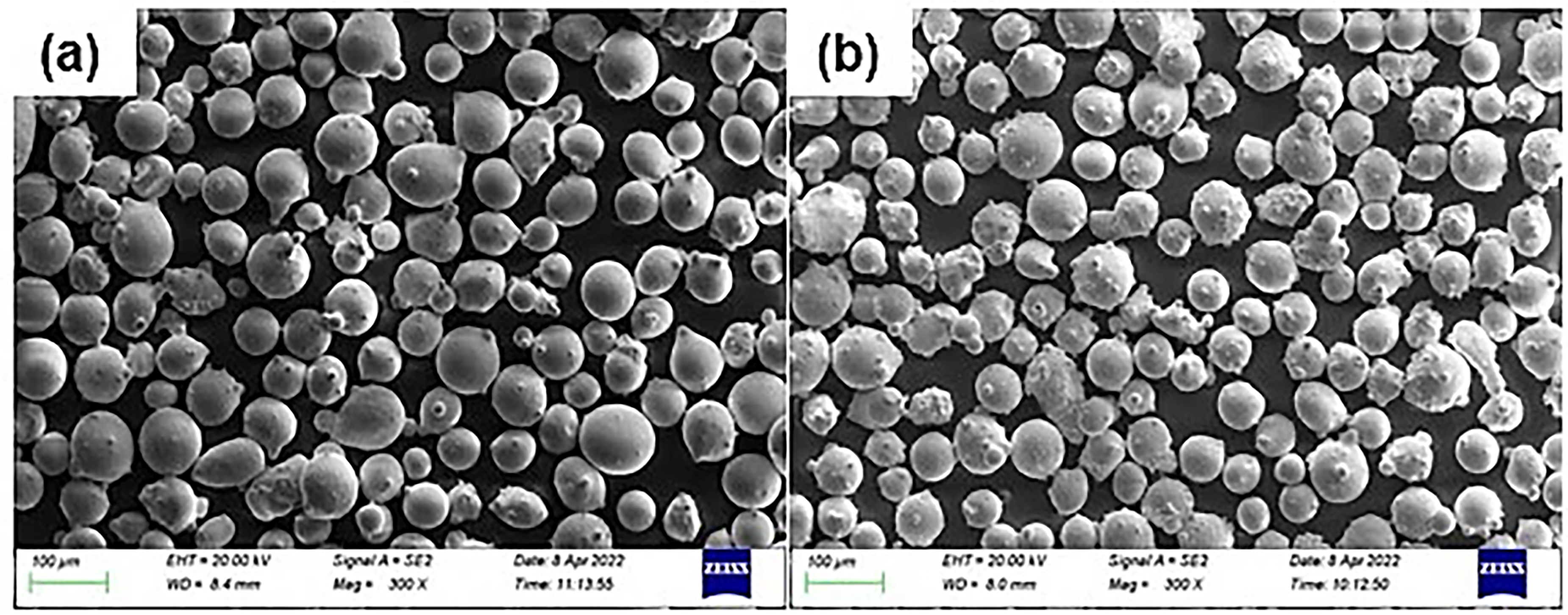
Scanning electron microscopy–backscattered electron images showing the morphology of Inconel 625 powder (a) and Inconel 718 powder (b).
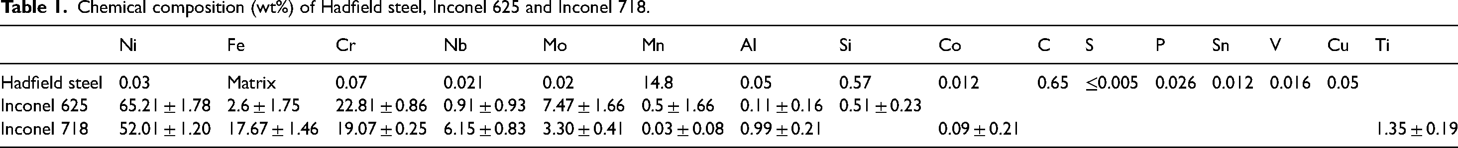
Chemical composition (wt%) of Hadfield steel, Inconel 625 and Inconel 718.
Laser cladding process
Four multi-tracks with four and six layers of Inconel 625 and 718 were cladded on the Hadfield steel substrate using a 3 kW IPG laser ytterbium doped fibre laser operating at a wavelength of 1070 nm, domicile at the Council for Scientific and Industrial Research's Photonics Centre in Pretoria, South Africa. The laser cladding machine, equipped with a Gaussian energy distribution, used in this study, is shown in Figure 2. The beam was focused on a round spot of 2 mm, 20 mm away from focus, with a stand-off distance of 12 mm. The Prectec YW50 fibre laser head was mounted on a six-axis KUKA robot machine. All deposition runs were carried out with argon gas as the shielding and carrier gas at a rate of 15 L/min and 2.5 L/min, respectively. All the depositions in this study were done with a Miller Thermal (Model 1264) powder feeder. The laser cladding parameters are shown in Table 2.
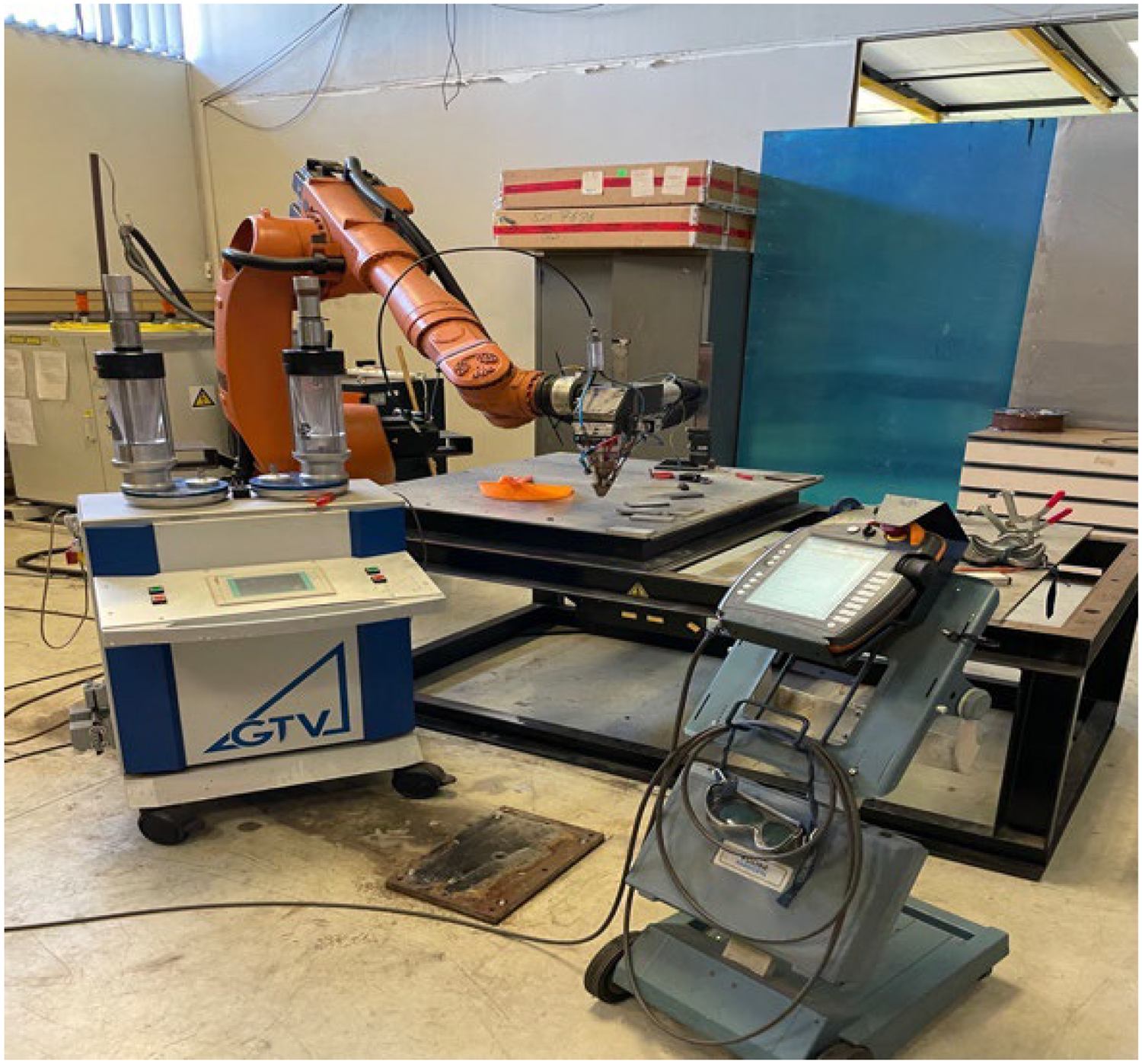
Laser cladding machine at the Council for Scientific and Industrial Research, Pretoria.
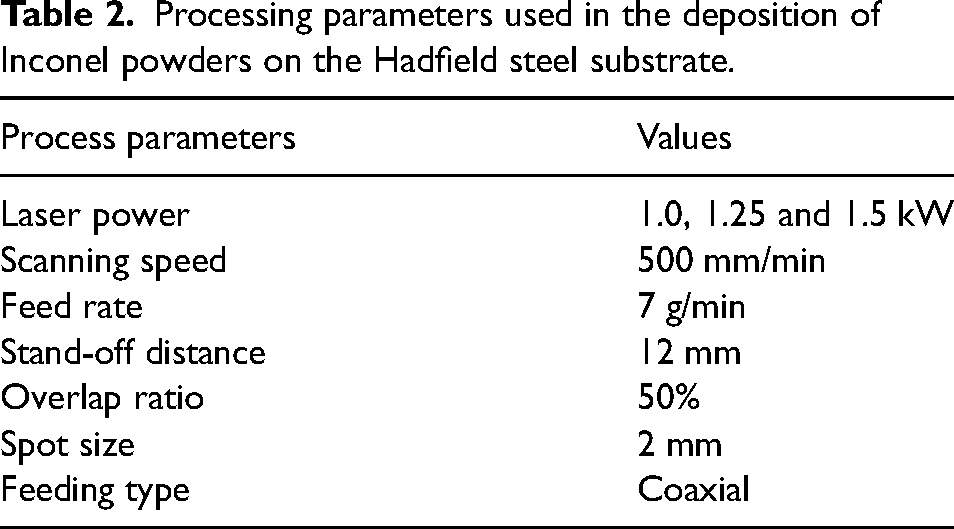
Processing parameters used in the deposition of Inconel powders on the Hadfield steel substrate.
Microstructural and phase examination
Prior to the metallographic procedure, the samples were cut using a Struers Secotom-10 abrasive cutting machine, with the wheel speed set at 3400 r/min, a feed speed of 0.020 mm/s and a cut length of 43 mm. The sectioned samples were mounted using a black Polyfast resin in an OPAL 410 hot mounting press. The mounted samples were ground and polished using standard techniques of metallographic preparation. For the microstructural analysis, samples were etched with Kalling's reagent containing 3% nitric acid and 97% ethyl alcohol. An Olympus optical light microscope, a stereo microscope, and a Carl Zeiss Sigma field emission gun scanning electron microscope equipped with backscattered electron (BSE), scanning electron, and EDX detectors operating at 20 kV (electron high tension). ZEISS SmartSEM software for data analysis was used to examine the microstructure and wear tracks of the clad. ImageJ software was used to measure the geometry of the clad. The dilution ratio of each sample was obtained using Equation (1).
17
This was achieved by determining the iron content (wt%) in the Inconel 625 and 718 clads.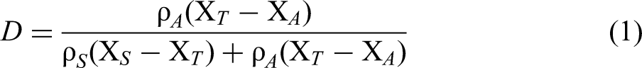
The densities of Inconel 625 and 718 are denoted by ρA and ρS, respectively. XS and XT are the composition of iron (wt%) in the base metal and the laser clad, respectively. The iron (wt%) composition in the Inconel 625 or Inconel 718 powder is denoted as XA.
The X-ray diffraction (XRD) patterns of the cladded Inconel 625 and 718 was examined using a Bruker D2 Phaser with cobalt-k
Hardness test
Hardness tests were carried out using the FM-700 microhardness tester set at a load and dwell time of 500 gf and 10 s, respectively. Pyramid-shaped diamond indentations were measured on the transverse sections from the substrate through the clad, with an average step size of 125 μm.
Wear test
A CSM ball-on-disc tribometer was used to measure the resistance to sliding wear of the cladded layer. A load of 5 N was applied, and an alumina ball with a 6 mm diameter was used according to the ASTM G 133-95 standard. The friction behaviour between the ball and the disc was assessed and presented using the coefficient of friction vs sliding distance obtained from the ball-on-disc CSM InstrumX software. A MarSurf PS 10 mobile roughness measuring device was used to measure the wear depth and width. Three-dimensional (3D) topography measurements of the scanning electron microscopy (SEM)-BSE images of the worn surface were analysed using the Gwyddion software. The sliding distance and the volume losses of the wear track of the disc were employed as control parameters, as specified in the ASTM G 99-15 standard. The wear rate was calculated using Equation (2).
18
The worn volume was calculated using Equation (3).
18
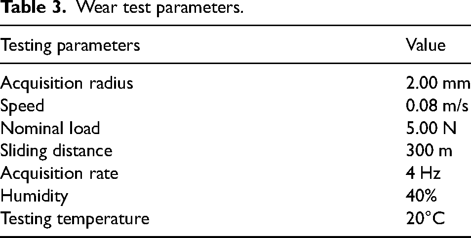
The wear test parameters used are shown in Table 3.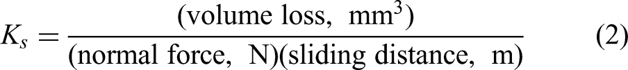

Wear test parameters.
Where Ks is the wear rate, Vw is the worn volume, ΔAw is the cross-sectional area of the wear track, and Pdmax is the maximum penetration depth.
Results
Effect of laser power on the dilution ratio of Inconel 625 and 718 clads
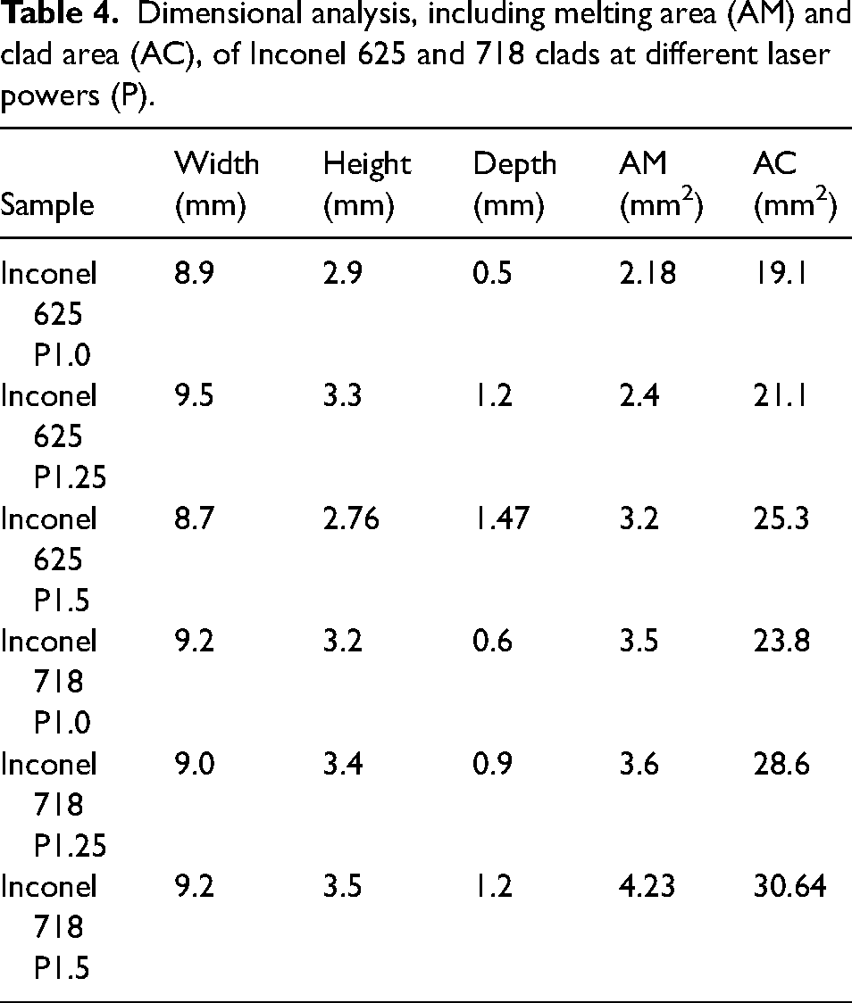
A schematic diagram of the cross-section of a typical Inconel clad on Hadfield steel is depicted in Figure 3, which highlights the cladding geometric features such as height, width, depth, clad area, and melting area. These geometrical characteristics of all claddings, with the results are presented in Table 4.
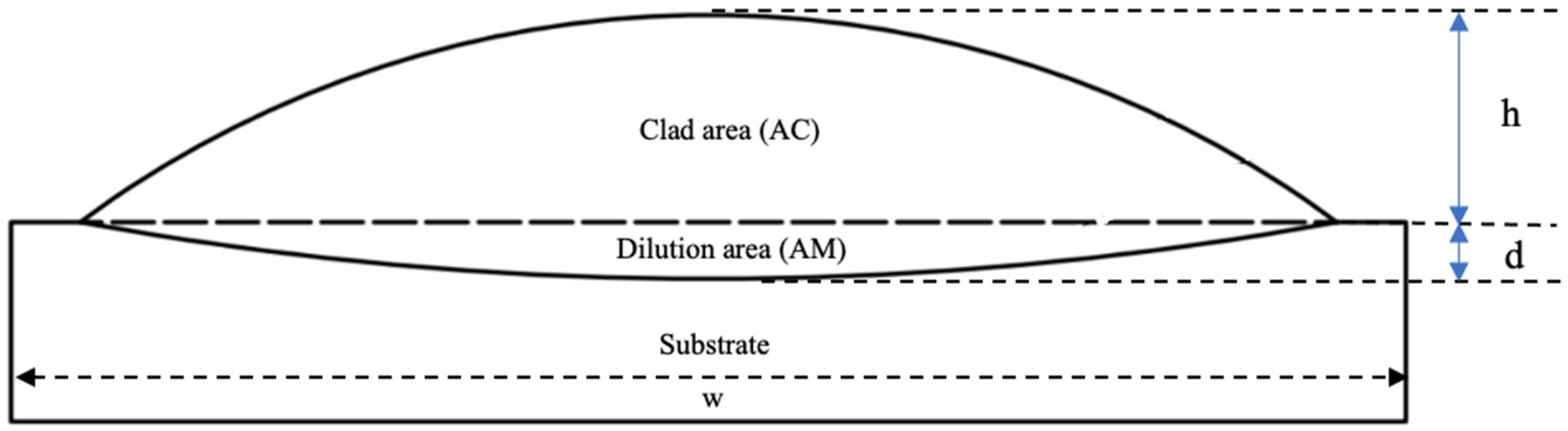
Cross-section of a typical Inconel clad on Hadfield steel showing the width (w), height (h), depth (d), melting area and clad area.
Dimensional analysis, including melting area (AM) and clad area (AC), of Inconel 625 and 718 clads at different laser powers (P).
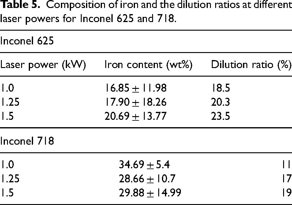
Excessive melting of the powders was observed when the laser power was set at 2 kW, producing distorted and inconsistent laser tracks. Laser tracks deposited at 1.0 kW to 1.5 kW were stable and produced consistent geometry while keeping the scanning speed and powder feed rate constant. The percentage of the total volume of the substrate material in the melt zone during cladding, known as the dilution ratio, was determined using the expected increase in the iron concentration in the deposited tracks because iron is the solvent element in the substrate. The iron content of Inconel 625 and 718 powders determined by EDX was 2.77 and 17.67%, respectively. The result of the SEM-EDX analysis, as detailed in Table 5, shows the iron composition in the area above the interface and its corresponding dilution ratios. The study by Ferreira et al. 24 showed that good clad properties can be expected when the dilution ratio is less than 30%. At laser powers of 1, 1.25, and 1.5 kW, Inconel 718 had dilution ratios of 11, 17, and 19%, respectively, while Inconel 625 had dilution ratios of 18.5, 20.3, and 23.5%, at the same power settings, showing that the depositions are within the acceptable limit. The dilution ratio increased with increasing laser power.3,17,31 One of the advantages of laser cladding over other conventional welding processes, such as shielded metal arc welding, is the low dilution rate.16,32 At the same laser power, Inconel 625 exhibited a higher dilution ratio than Inconel 718, despite having a lower initial iron content. This behaviour could be attributed to Inconel 625's superior fluidity, which results from its composition and stable microstructure. These properties promote greater dispersion and wetting upon contact with the molten Hadfield steel substrate, leading to deeper substrate melting and, consequently, greater dilution. A higher dilution rate means that a thicker layer of the substrate must be melted to achieve proper metallurgical bonding while maintaining the desired properties of the coating material.24,33,34 However, excessive dilution could alter the composition of the cladding material, potentially degrading the original performance of the alloy and increasing the susceptibility to cracking in the cladding layer. 33
Composition of iron and the dilution ratios at different laser powers for Inconel 625 and 718.
Microstructural characterisation of Inconel 625 and 718 clads
The stereo microscope images of the transverse sections of the clads are shown in Figure 4. No visible macroscopic defects were observed at the interface of the base metal and the Inconel clads, suggesting the existence of a strong bond. The images obtained from the stereo microscopy were used to determine the clad geometry, and the dilution ratio was computed.
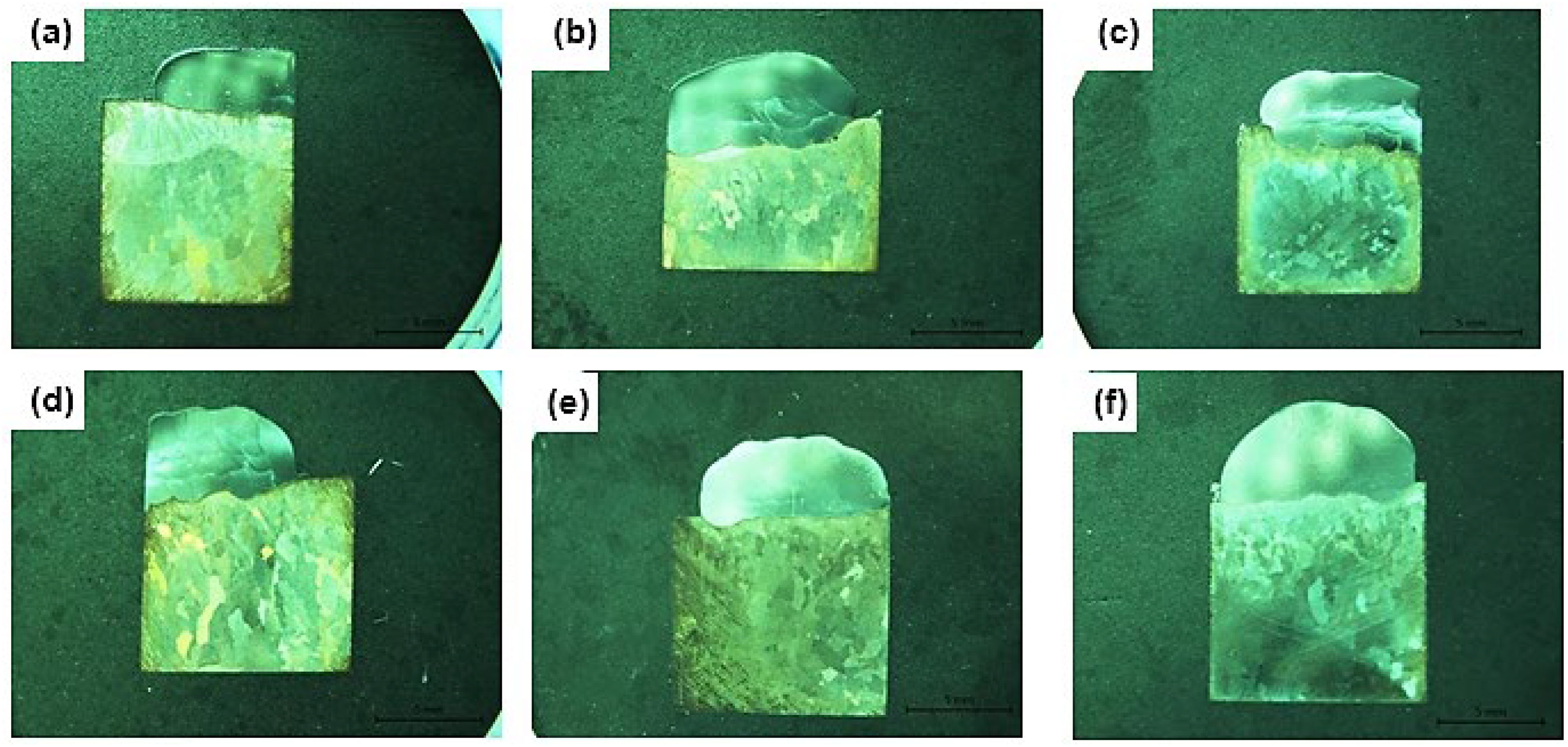
Stereo microscope images of Inconel 625 at a laser power of 1 kW (a), 1.25 kW (b), 1.5 kW (c). Stereo microscope images of Inconel 718 at a laser power of 1 kW (d), 1.25 kW (e), 1.5 kW (f).
The grain sizes of the clads are shown in Supplementary Table 1. At laser powers of 1 kW and 1.5 kW, the average grain size of the Inconel 625 clad was 4.98 ± 191.1 μm and 3.68 ± 50.6 μm, respectively (Figure 5). On the other hand, the average grain size of Inconel 718 clad at laser powers of 1 kW and 1.5 kW was 4.96 ± 67.7 μm and 7.62 ± 122.7 μm, respectively (Figure 6). This trend suggests that, unlike Inconel 625, which exhibited a decrease in grain size with increasing laser power, the grain size of Inconel 718 clad increased with increasing laser power. The difference in grain size is due to the compositional and microstructural make-up of the two alloys. Epitaxial grain growth led to the formation of columnar dendrites that are visible in the upper half of the cladded layer, thereby determining the direction of grain growth in this region. Also, the direction of the laser scanning determines the growth direction of columnar dendrites. 35 Finer grains were also observed at the lower and upper sections of the Inconel clads, and this may be because of rapid cooling characterised by these regions.
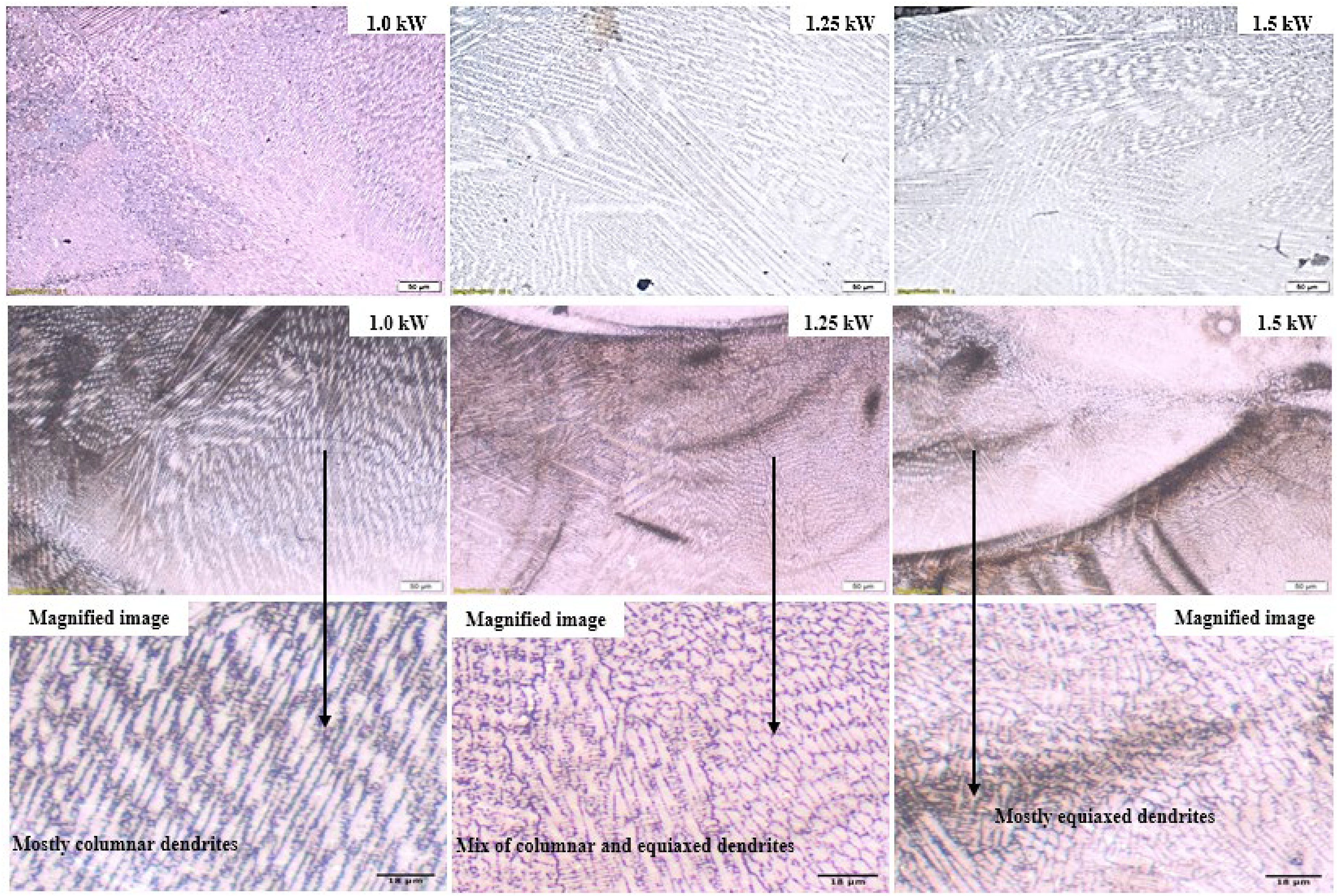
Optical images of Inconel 625. The upper region (top row) is the top clad region, and the lower region with magnified images (second and third rows) is the clad-substrate section.
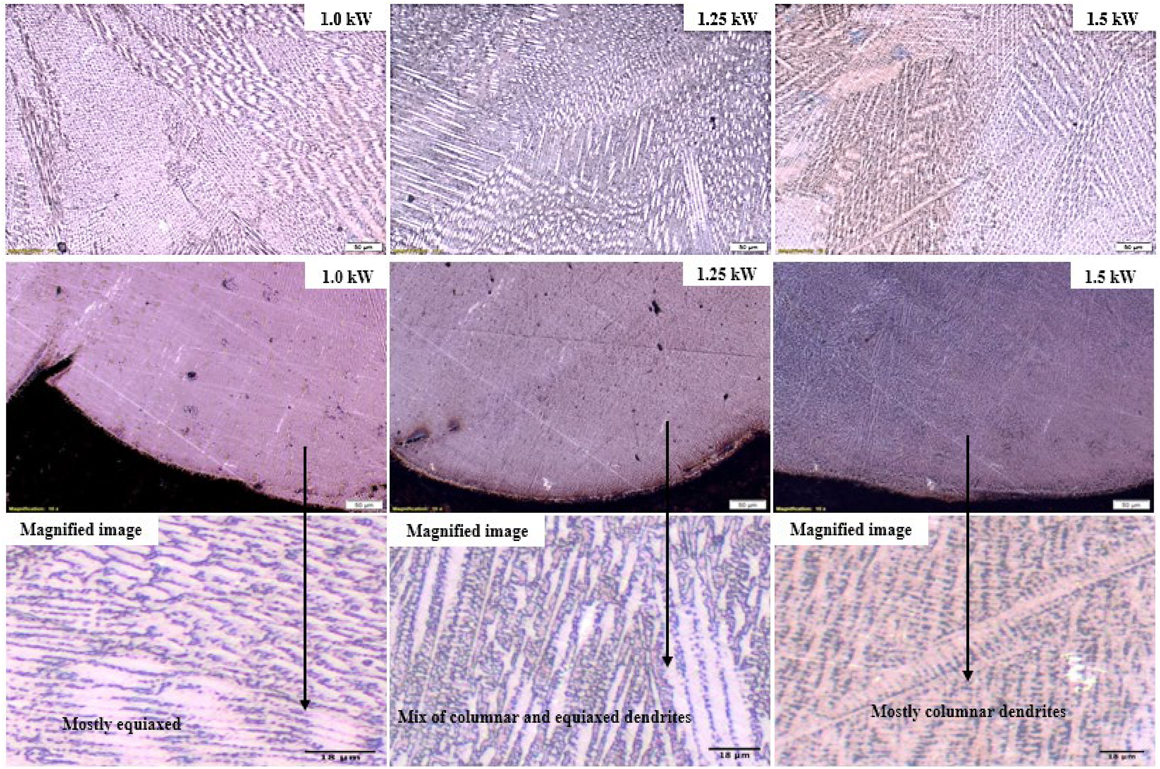
Optical images of Inconel 718. The upper region (top row) is the top clad region, and the lower region with magnified images (second and third row) is the clad-substrate section.
The microstructures of Inconel 625 and 718 clads on Hadfield steel are different for the same laser power (Figures 5 and 6). The Inconel 625 clads exhibited a finer grain structure, while the Inconel 718 had a coarse microstructure at the same laser power. The microstructure of the Inconel 625 clads was composed primarily of equiaxed dendrites with a small number of columnar dendrites, whereas the Inconel 718 clads had fewer equiaxed and more columnar dendrites. The predominant cellular/equiaxed dendrite grain structure found in the powder track is evidence of the rapid rate of solidification. 36 Columnar dendrites were observed growing horizontally near the top of the Inconel 625 clad structure. This could be attributed to variations in the form of the melt pool, causing changes in the direction of heat flux, which can modify the direction of columnar dendrite growth,35,37 as seen in Figures 5 and 6. The top of the cladding layer's microstructure becomes exceedingly fine and irregular. These irregularities may be caused by heat escaping primarily into the atmosphere, greatly diminishing the influence of the temperature gradient.
Deposited Inconel 625 clad was observed to have some cracks, as shown in Figure 7. The cracks may have been eliminated by varying other process parameters such as the scanning speed and powder feed rate.13,17,38 A prominent disadvantage of laser cladding (laser direct deposition) has been the existence of cracks in laser coatings. 39 Residual stresses that accumulated during the solidification of the melt as a result of the temperature gradient between the clad and substrate led to the formation of cracks. 39 Cracks are initiated whenever the total thermal stresses exceed the toughness of the solidifying clad. 39 Therefore, crack propensity is high in laser-deposited coatings because of the localised heating of the laser beam and quick solidification characterised by laser cladding processes. 39 In this study, cracks were observed in the Inconel 625 coatings. The lower grain size and higher hardness values could have contributed to the formation of cracks. 39 However, pre- and post-weld heat treatments can be applied to refine grains and prevent cracks from forming in laser cladding.18,40,41 The laser cladding parameters used in this study were found to be more suitable for the Inconel 718 clads. Nonetheless, optimisation of laser cladding parameters may be required to achieve crack-free deposits of Inconel 625 on Hadfield steel.
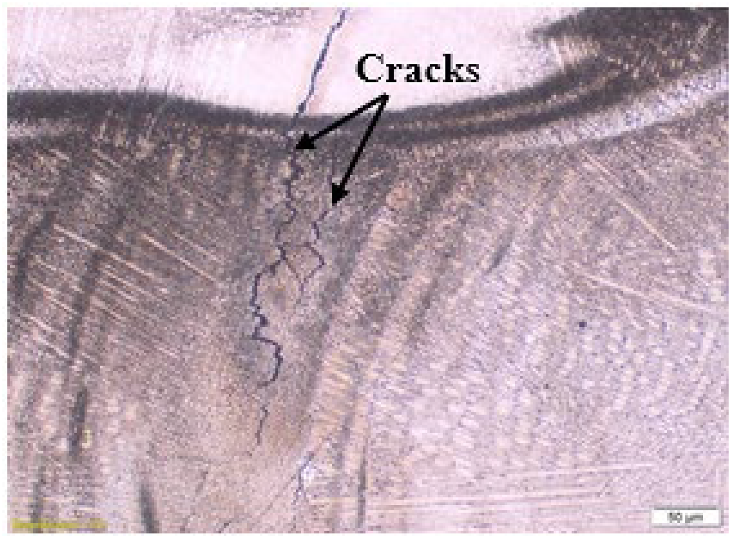
Optical micrograph of Inconel 625 at 1.5 kW laser power.
X-ray diffraction analysis
The XRD analyses in Figure 8 show that the dominant phase identified in both samples is γ-nickel with a face-centred cubic (FCC) crystal structure. The γ-nickel with an FCC crystal structure has also been observed in the Inconel 625 and 718 clads.23,29,42,43 Inconel 625 had precipitates of niobium at a laser power of 1.0 kW, with the principal peaks at 2Theta = 51.8°, 60.6°, and 91.1° (Figure 8(a)). At laser powers of 1.25 kW and 1.5 kW, Inconel 625 had precipitates of chromium with its principal peaks at 2Theta = 51.4°, 60.1°, and 90.2°, and 52°, 60.8°, and 91.4°, respectively (Figure 8(b) and 8(c)). Inconel 718 had precipitates of chromium at a laser power of 1.0 kW with principal peaks at 2Theta = 51.7°, 60.5°, and 90.8°, iron at a laser power of 1.25 kW with principal peaks at 2Theta = 51.5°, 60.3°, and 90.4°, and molybdenum at a laser power of 1.5 kW with principal peaks at 2Theta = 51.0°, 59.7°, and 89.4° (Figure 8(d)–(f)). Chromium, iron, niobium, and molybdenum-rich precipitate phases have been previously reported in Inconel 625 and 718 clads.25,44
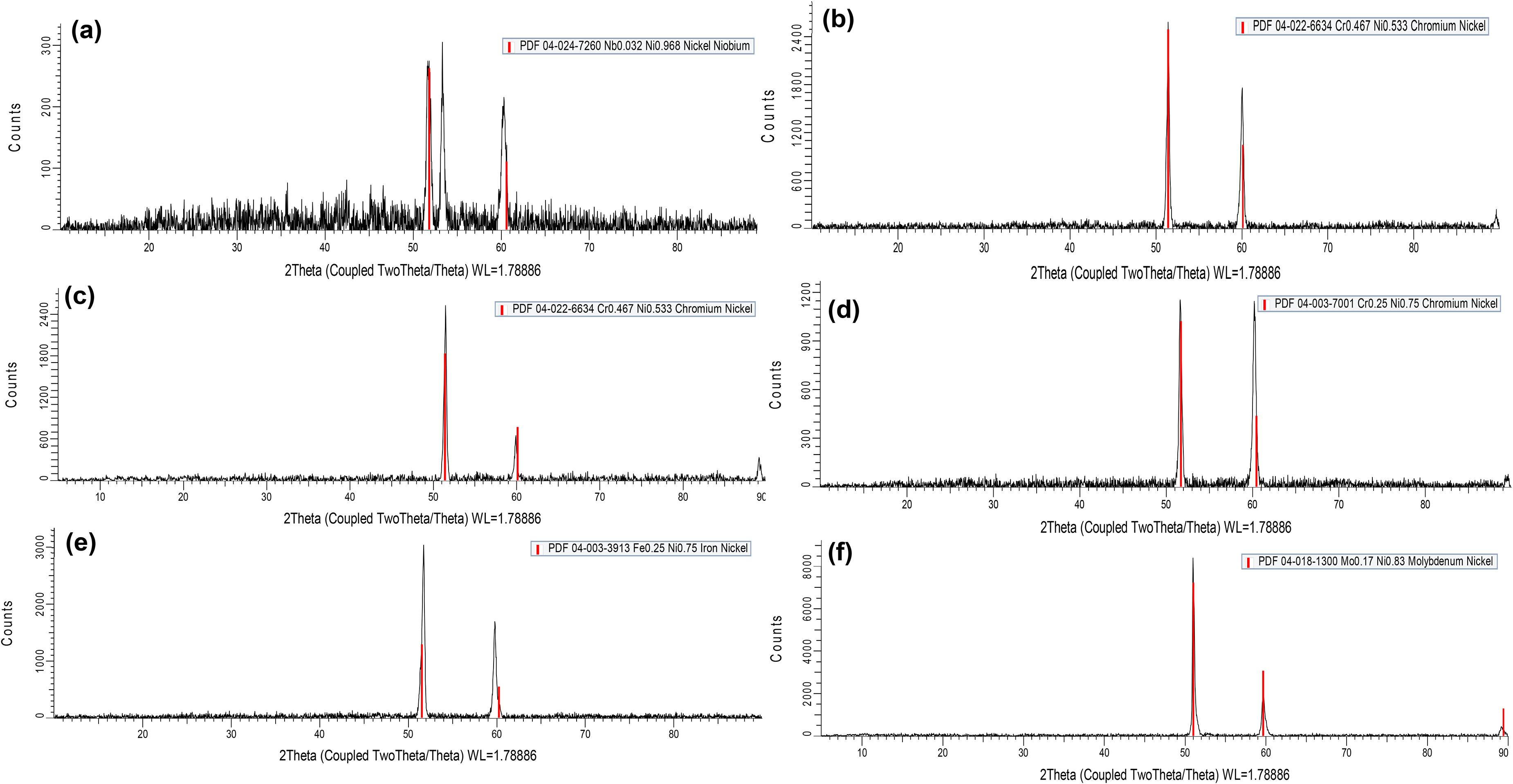
X-ray diffraction patterns of a) Inconel 625 at a laser power of 1.0 kW, b) Inconel 625 at a laser power of 1.25 kW, c) Inconel 625 at a laser power of 1.5 kW, d) Inconel 718 at a laser power of 1.0 kW, e) Inconel 718 at a laser power of 1.25 kW, f) Inconel 718 at a laser power of 1.5 kW.
SEM analysis of phases in Inconel 625 and 718 laser clads
The SEM images show a bright contrast precipitate labelled ‘B’ and a dark continuous nickel matrix phase denoted ‘D’ in the grain boundaries (inter-dendritic) of the laser tracks, as shown in Figure 9(a) and (b), respectively. For comparison, Figure 9(c) shows a similar image of Laves, which were observed during the laser deposition of Inconel 718. 45 SEM-EDX spot analysis was carried out on the Inconel 625 and 718 clads, as shown in Supplementary Tables 2 and 3. The bright precipitate at the interdendritic area was rich in chromium, iron, niobium, and molybdenum. Parimi et al. 43 identified these precipitates as the Laves phase. Li et al. 46 reported that high atomic mass elements, such as niobium and molybdenum, segregate inside dendritic core limits of nickel-based superalloys (i.e., grains with a higher wt% of chromium, nickel, and iron).
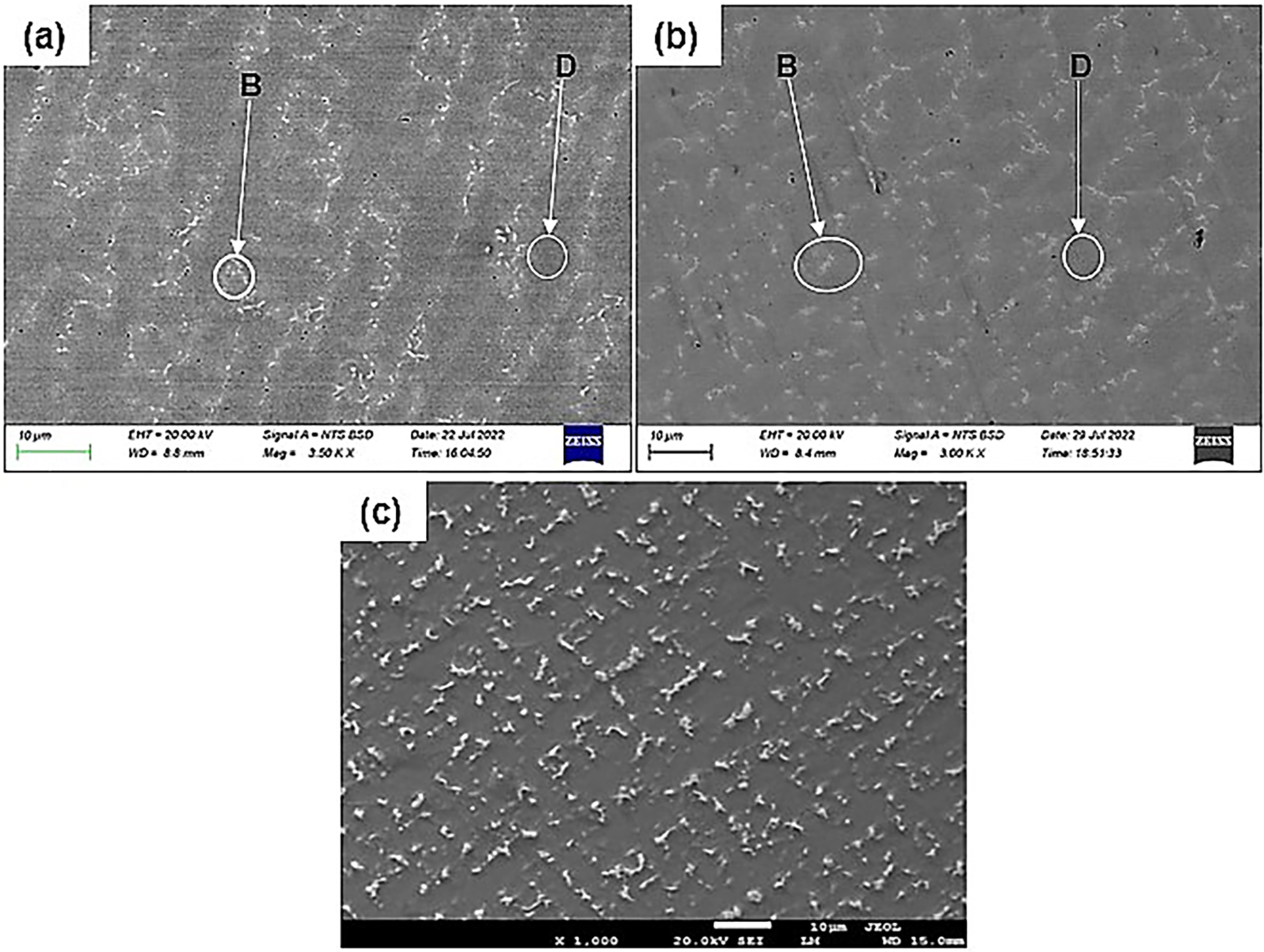
SEM image of Inconel a) 625 and b) 718 at a laser power of 1.25 kW showing bright precipitates (B) and the nickel-rich matrix (D). Image c) Laves formation in an Inconel 718 deposit. 45
The precipitation mechanism of Inconel 625 and 718 is intricate and dependent on the chemical composition of the alloy and time-temperature history.43,47 The solidification products in nickel-based superalloys are influenced by the presence of elements such as niobium, silicon, and carbon.43,47 This is due to the elements having a high propensity to form secondary phases (precipitates) within the grain boundaries during the latter stages of solidification.43,47 These secondary phases could lead to the formation of cracks, thus compromising mechanical properties such as ductility, fatigue life, ultimate tensile strength, and fracture resistance.24,25
Typically, the production of dendrites deficient in high atomic elements, most notably niobium and molybdenum at their cores, marks the beginning of the solidification of an Inconel 625 and 718 deposit. 47 Iron, nickel, and chromium migrate to the solidifying γ-nickel dendrites as solidification spreads outward from the dendritic cores, but niobium and molybdenum remain segregated to the liquid phase. The interdendritic liquid gains more niobium and molybdenum as the solidification progresses, eventually reaching Laves eutectic composition. At this point, the solidification is complete, and the components of Laves are formed. 47 The segregation of niobium and molybdenum in the precipitates shows that they are important constituents of the Laves phase. The melting and precipitation temperature of the Laves phase ranges from 923 K to 1373 K (650°C to 1100°C), and the maximum melting and precipitation temperature varies depending on the constituents. 45 This shows that the melt pool temperature in this study reached the 650°C to 1100°C temperature range for forming Laves. Since the EDX results in this study showed niobium and molybdenum-rich precipitates in the interdendritic region of the Inconel clads, it is concluded that these precipitates are the Laves phase.
Microhardness
Hardness is a crucial parameter for evaluating the properties of a material. The hardness profiles of Inconel 625 and 718 clads are shown in Figure 10(a) and (b), respectively. The vertical axis depicts the microhardness measurements at each position on the transverse section, while the horizontal axis indicates the distances along the transverse section from the interface into the substrate (heat affected zone [HAZ]). Prior to cladding, the substrate had microhardness values of 213 ± 11.9 HV. However, upon cladding, it was found that the hardness of the substrate at the HAZ was as high as 339 ± 26.15 HV and 380 ± 66.85 HV in the Inconel 625 and 718 clads, respectively. This demonstrated that a rapid cooling rate caused the HAZ to become substantially harder. 24 Inconel 625 was observed to have an average microhardness value of 248 ± 13.56 HV and 269 ± 38.27 HV at a laser power of 1.0 kW and 1.5 kW, respectively. Inconel 718 had an average microhardness value of 243 ± 12.01 HV and 212 ± 12.38 HV at a laser power of 1.0 kW and 1.5 kW, respectively. These results show that Inconel 625 at a laser power of 1.5 kW and Inconel 718 at a laser power of 1.0 kW cladded on Hadfield steel gave a higher microhardness value.
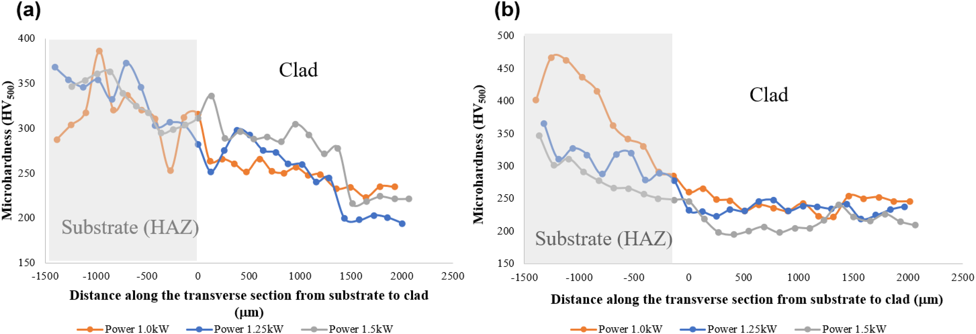
Microhardness readings along the transverse section of a) Inconel 625 clad and b) Inconel 718 clad.
The rapid cooling associated with laser cladding processes is the reason for the increase in hardness of the HAZ; however, the hardness obtained in the clads in this study was higher than the hardness of the substrate. The Hall-Petch equation states that grain size and microhardness are inversely related because harder materials tend to have smaller grains, which makes for more effectiveness at impeding dislocation movement when compared to larger grains. 48 From the investigation, it was found that the hardness of Inconel 625 increased with increasing power (Figure 10(a)). The opposite was observed with Inconel 718, where the hardness decreased with increasing power (Figure 10(b)). Since higher hardness is linked to a finer grain structure, the reason for that behaviour in the Inconel 625 clads can be explained by the evolution of more equiaxed dendrites at a power of 1.5 kW compared to more columnar dendrites at a power of 1.0 kW. Columnar dendrites and grain growth were observed in the Inconel 718 clad when the laser power increased to 1.5 kW, which led to a decrease in hardness. Although microhardness values did not increase with increasing power in the Inconel 718 samples, the microhardness was directly proportional to the grain size according to the Hall-Petch rule. Microhardness was 243 ± 12 HV for Inconel 718 at a laser power of 1 kW and 212 ± 13 HV at a laser power of 1.5 kW, showing that samples with a finer grain size had the highest microhardness.
Dry sliding wear
The wear resistance is influenced by the hardness of a material. According to Archard's wear law, mass loss is inversely related to material hardness and directly proportional to the applied load and the travel distance. 23 The Inconel 625 clads had the lowest grain size and highest microhardness at relatively higher laser powers of 1.25 kW and 1.5 kW. The Inconel 718 clads, on the other hand, had the lowest grain size and the highest microhardness at lower laser powers of 1.0 kW and 1.25 kW. Therefore, wear tests were carried out on the samples with the two highest microhardness values among the three laser powers used for each superalloy. Single-layer clads and five multi-layer clads for each Inconel 625 and 718 were produced to ascertain the effect of coating thickness on the wear behaviour of the cladded layer. Figure 11 shows images of clads at different heights. Inconel 625 and 718 multi-layer clads are denoted with the symbol ‘H’, while the single-layer clads are denoted ‘L’ for the different laser power settings (i.e., 1.0, 1.25, and 1.5 kW).
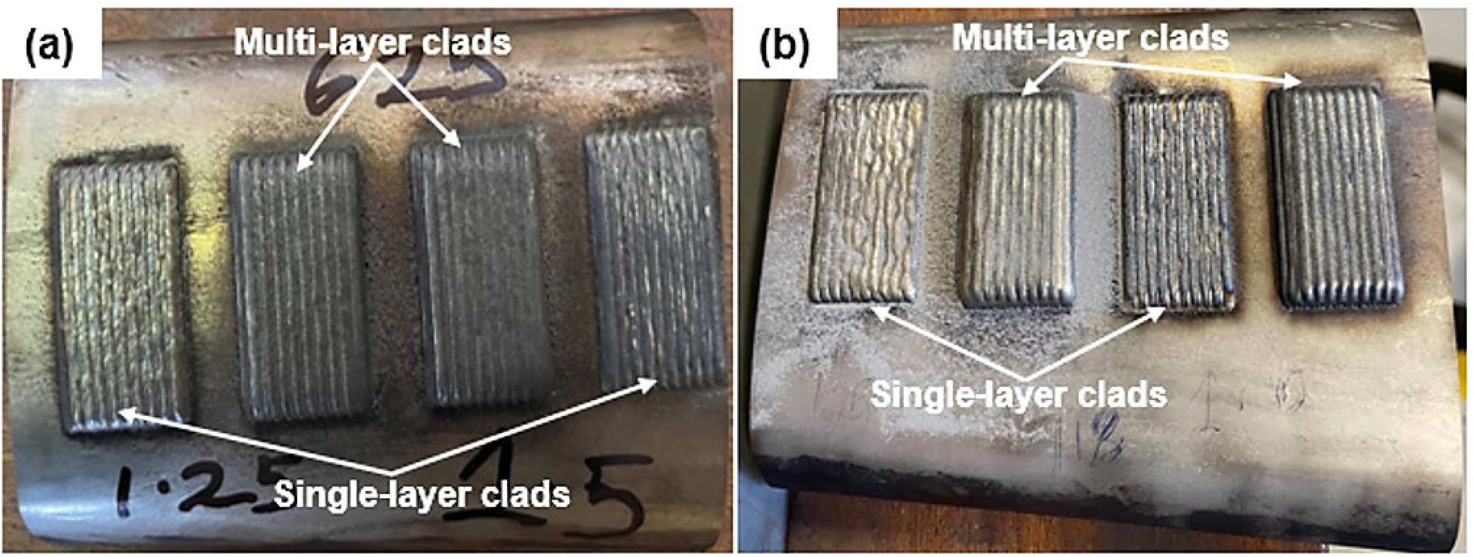
Single-layer and multi-layer clads of Inconel 625 (a) and Inconel 718 (b).
The wear rates and worn volumes of the samples were calculated using Equations (2) and (3), and the results are presented in Supplementary Table 4. The Hadfield steel sample had the lowest wear rate of all the samples at 7.17 × 10⁻⁴ mm3/Nm. This was due to the ability of the sample to work harden. The hardness of the samples did not correlate with the wear rate of the Inconel samples in this study. The Inconel 625 1.25H had the lowest wear rate of 2.46 × 10⁻³ mm3/Nm among the Inconel 625 samples. The Inconel 718 1.25L had the lowest wear rate of 2.31 × 10⁻³ mm3/Nm among the Inconel 718 samples. Although according to Archard's wear law, mass loss is inversely related to material hardness and directly proportional to the applied load and travelled distance, 23 it is expected, according to this law and other studies, that the higher the hardness, the lower the wear rate. However, for the Inconel samples, this was not the case, which could be attributed to the microstructure, plastic strain, and plastic flow, which are also major contributing factors to the wear behaviour of a material. 49 Also, the type of wear test carried out, as well as the parameters used in testing, have been observed to affect the wear behaviour of materials.50–52
The measured values of the friction coefficient were plotted as a function of sliding distance. The change in coefficient of friction across the samples is due to the difference in microstructure when at steady state. 6 Figure 12 shows the friction coefficient graphs for the Inconel 625, Inconel 718, and Hadfield samples. Hadfield steel was observed to have an increasing coefficient of friction from 25 to 200 m sliding distance and became stable from 200 to 300 m. However, for the Inconel 625 samples, the coefficient of friction was seen to increase and then decrease to a relatively steady state from a sliding distance of 50 to 300 m (Figure 12(a)). Hadfield steel had a higher and increasing coefficient of friction than the Inconel 625 and 718 cladded samples because of its ability to work harden, which is its major distinguishing factor from other steels. 6 Hadfield steel showed the least wear rate, penetration depth, track width, and worn volume when compared to the Inconel samples. The Inconel 625L wear tracks had the lowest coefficient of friction at 0.6 μ, and the Inconel 625H tracks had the highest coefficient of friction at 0.68 μ (Figure 12(a)). For the Inconel 718 samples, the coefficient of friction was seen to increase and then decrease to a relatively steady state from a sliding distance of 35 to 300 m (Figure 12(b)). The Inconel 718 1.25L wear tracks had the lowest coefficient of friction at 0.57 μ, and the Inconel 718H tracks had the highest coefficient of friction at 0.63 μ.
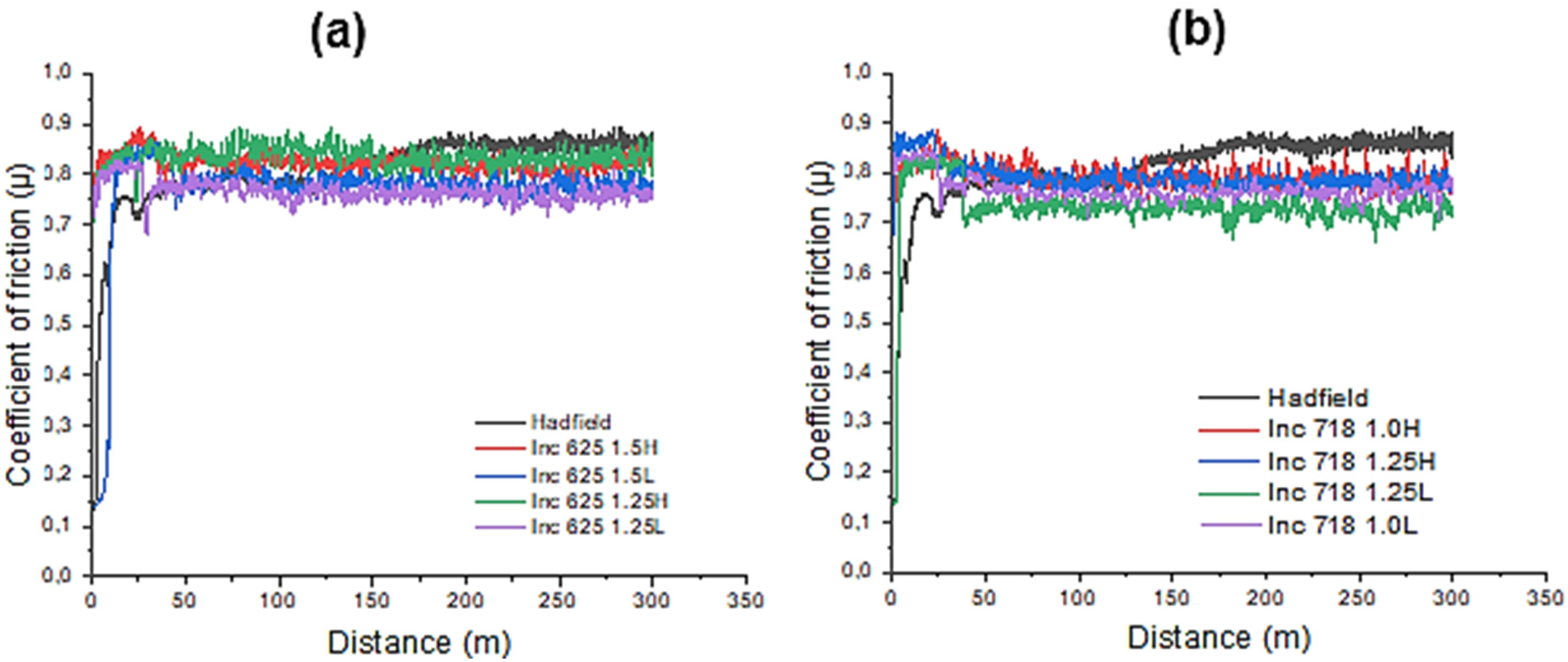
Superimposed coefficient of friction vs. sliding distance of (a) Inconel 625 and Hadfield steel, and (b) Inconel 718 clads and Hadfield steel.
The SEM-BSE images in Figure 13 show wear tracks for Hadfield steel and the Inconel 625 and 718 samples. The Hadfield steel samples exhibited thinner wear scars due to their resistance to sliding wear, whereas the Inconel 625 and 718 samples had larger wear scars, indicating lower wear resistance. The main wear mechanisms observed in the Hadfield steel were micro-ploughing, micro-cutting, and delamination wear.53,54 The Hadfield steel had small islands of black patches, also known as wear debris (Figure 13(a) and (b)), and were more prominent in the Inconel 625 and 718 wear tracks (Figure 13(c)–(f)). The EDX analysis revealed higher oxygen content in the debris than in the Inconel samples (Supplementary Table 5), suggesting oxidation wear in the Hadfield steel.54,55 Wear grooves were created on the surfaces of the Inconel samples, thereby ejecting wear debris trapped in the grooves and reducing friction between the mating surfaces due to the abrasive wear caused by the higher hardness of the alumina ball compared to the samples. The oxide layers formed in the worn grooves acted as a lubricant, reducing friction at the interface between the samples and the alumina ball, which most likely resulted in a decrease in wear rate and caused the variations in coefficients of friction. Additionally, some debris that either got lost or stayed in the contact zone during testing moved freely between the sliding surfaces, ploughing both the test specimen and the alumina ball. Inconel 625 1.5H had the highest wear debris compared to the other Inconel 625 wear tracks. Also, Inconel 718 1.0H had the highest wear debris compared to the other Inconel 718 wear tracks. It was observed that the major wear mechanisms in the Inconel wear tracks were abrasive and adhesive. Abrasive wear is characterised by the formation of grooves due to ploughing and cutting during the sliding process. 56 Adhesive wear, however, has to do with material transfer between the ball and the wear track. 56
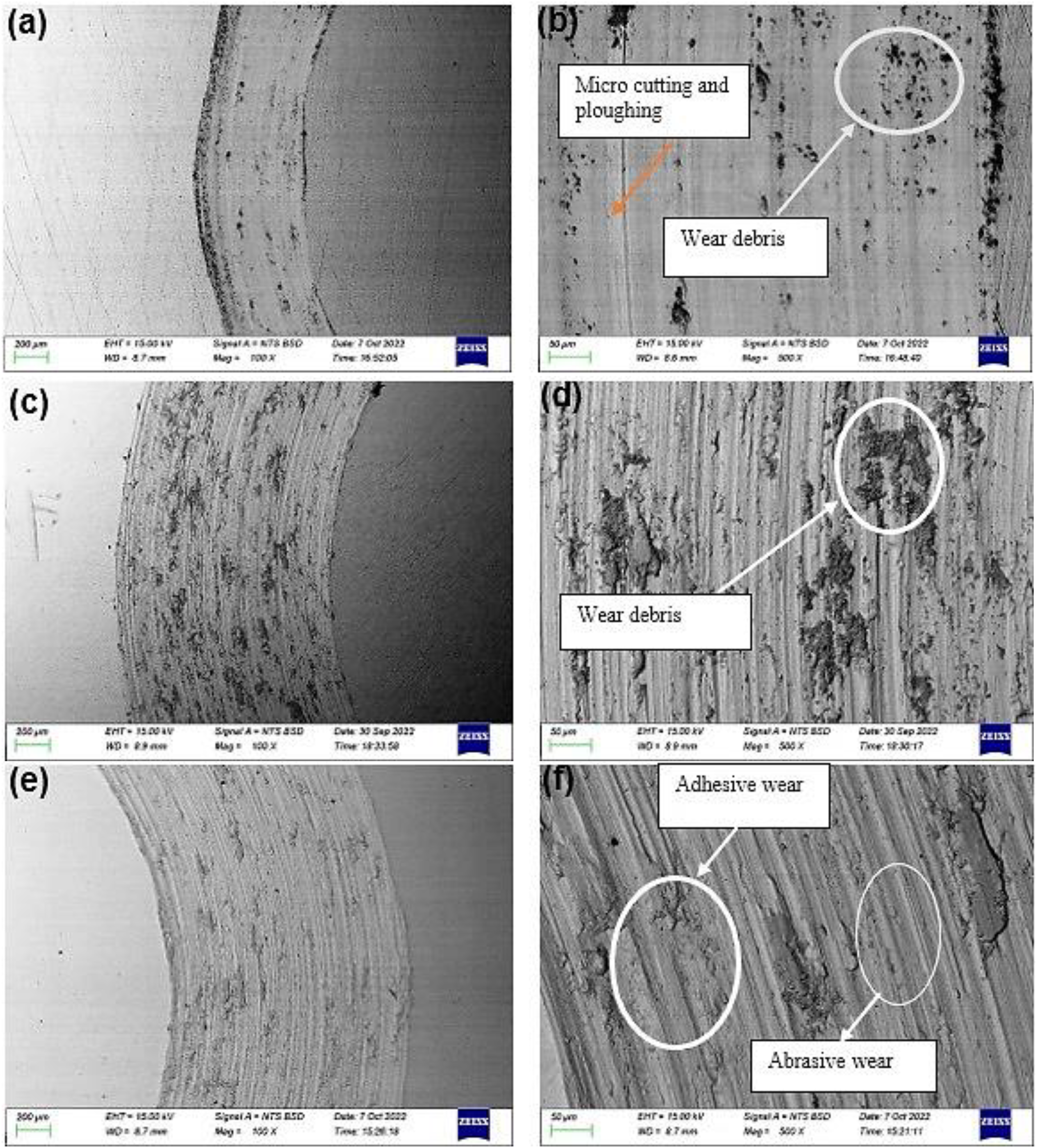
SEM-BSE images of wear tracks of Hadfield steel (a and b), Inconel 625 (c and d), and Inconel 718 (e and f).
The 3D topography of the worn surface of the Hadfield steel and the Inconel 625 and 718 is shown in Figure 14. It was observed that the surface of the Hadfield steel was not as rough as that of the Inconel wear tracks. The Inconel 625L wear tracks were observed to have a higher roughness than the Inconel 625H tracks. The surface roughness values of the Hadfield and Inconel wear tracks are shown in Figure 15. Hadfield steel had the lowest surface roughness value of 36 nm. Inconel 625 1.5H had the lowest surface roughness value, and Inconel 625 1.25L had the highest surface roughness value among the Inconel 625 wear tracks.
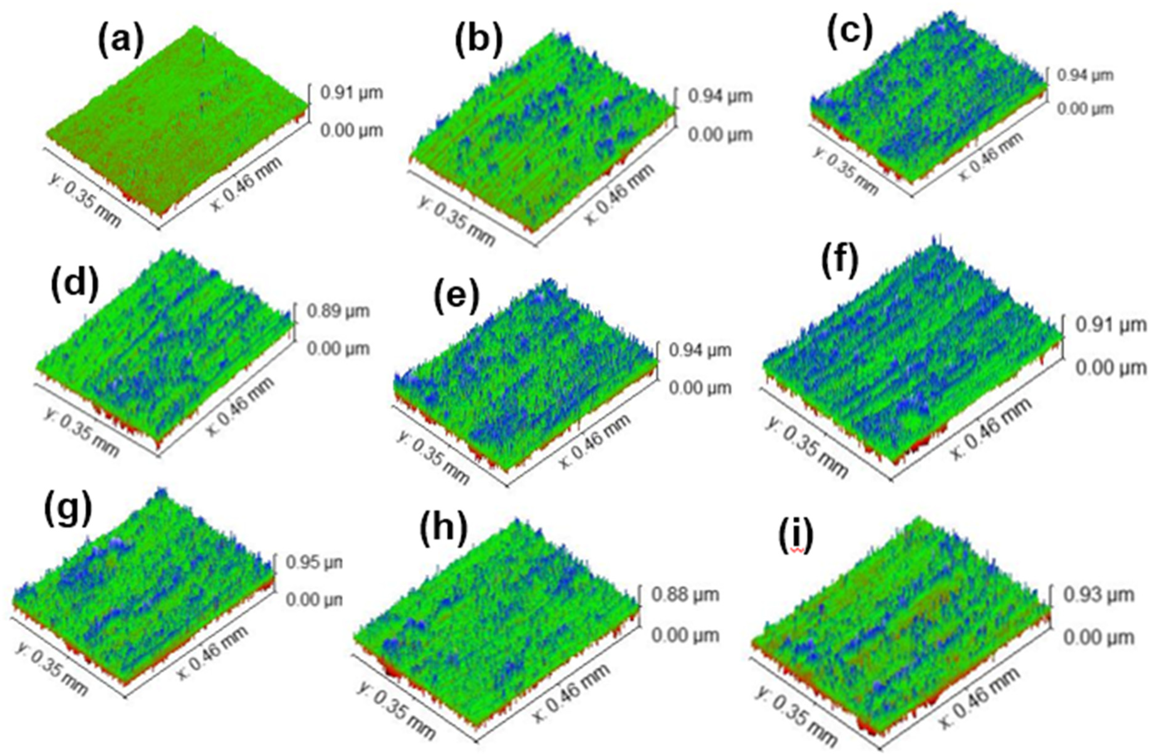
3D topography of the worn surface of a) Hadfield steel, b) Inconel 625 1.5H, (c) Inconel 625 1.5L, (d) Inconel 625 1.25H, (e) Inconel 625 1.25L, (f) Inconel 718 1.0H, (g) Inconel 718 1.0L, (h) Inconel 718 1.25H, and (i) Inconel 718 1.25L.
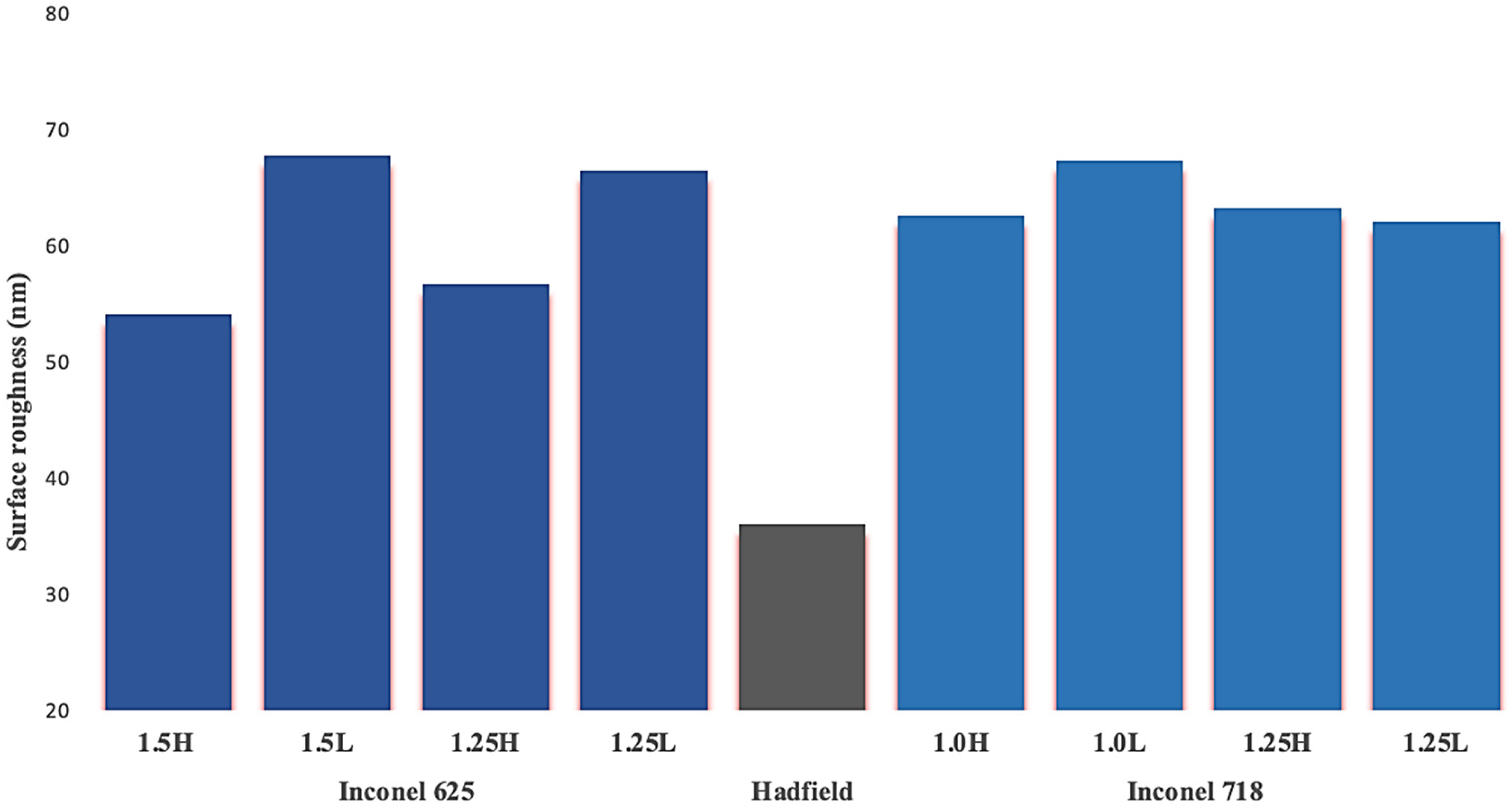
Surface roughness values of the samples.
The Hadfield steel sample had a lower surface roughness than the Inconel 625 and 718 wear tracks, as seen in Figure 15. The Inconel 718 1.0L had the highest surface roughness, as shown in Figure 15, while the Inconel 718 1.25L had the lowest surface roughness. Inconel 718 wear tracks, however, were observed to have a higher surface roughness than the Inconel 625 tracks.
Conclusion
A study of Inconel 625 and 718 powders deposited on Hadfield steel was successfully carried out as a potential alternative to traditional hardfacing methods for rail crossings. The Inconel 625 and 718 clads exhibited columnar and equiaxed dendritic structures, with columnar dendrites growing perpendicular to the substrate. Molybdenum- and niobium-rich precipitates were found in the interdendrite regions of the Inconel 625 and 718 clads. Cracks were observed in the Inconel 625 clads, which could be mitigated through further optimisation of laser cladding parameters and the application of pre- and post-weld heat treatments. Microhardness analysis revealed that the Inconel 625 clad reached a peak value of 269 HV at 1.5 kW laser power, whereas the Inconel 718 clad reached 243 HV at 1.0 kW. The increase in microhardness for the Inconel 625 clad with increasing laser power was attributed to the formation of more equiaxed grains, while Inconel 718 clad showed a reverse trend. In both cases, lower grain sizes correlated with higher microhardness values. Wear analysis showed that Hadfield steel primarily undergoes micro-ploughing, micro-cutting, delamination, and oxidation wear. In contrast, the Inconel 625 and 718 clads majorly exhibited abrasive and adhesive wear. These findings suggest that laser cladding of Inconel 625 and 718 on Hadfield steel can significantly enhance surface hardness and wear resistance, which are key requirements for rail crossings subjected to high-impact and cyclic loading in high-speed and heavy-haul rail systems. The higher hardness of the Inconel clads, when properly processed, offers viable paths for extending the service life and reducing maintenance needs in rail infrastructure such as rail crossings. Optimising processing conditions will be critical to minimise defects like cracking and to fully leverage the wear-resistant properties of these superalloys in demanding rail environments.
Future studies should consider varying other laser cladding parameters, such as scanning speed and powder feed rate, to minimise cladding defects. The application of pre- and post-heat treatments on laser clads is recommended to prevent crack formation and reduce the detrimental effects of Laves phases on the properties of the cladded layer. The investigation and identification of carbides in the microstructure could be enhanced using higher-resolution imaging techniques, such as transmission electron microscopy and electron backscatter diffraction. Additional mechanical tests, such as cyclic loading, corrosion, and impact tests, may be carried out on the clads to further assess their suitability for repairing rail crossings. Further research should also explore alternative hardfacing alloys with superior hardness and wear properties for use in laser cladding applications on rail crossings.
Supplemental Material
sj-docx-1-pil-10.1177_14644207251362598 - Supplemental material for Microstructure, hardness, and wear behaviour of laser-cladded Inconel 625 and 718 powders on Hadfield steel
Supplemental material, sj-docx-1-pil-10.1177_14644207251362598 for Microstructure, hardness, and wear behaviour of laser-cladded Inconel 625 and 718 powders on Hadfield steel by Iyanu Williams, Nthabiseng Maledi, Olufemi Sylvester Bamisaye, Michael Bodunrin, Samuel Skhosane and Thulani Sitimela in Proceedings of the Institution of Mechanical Engineers, Part L: Journal of Materials: Design and Applications
Footnotes
Acknowledgements
The Council for Scientific and Industrial Research, National Laser Centre in Pretoria, South Africa.
Data availability statement
The data required to reproduce these findings is available upon request.
Declaration of conflicting interests
The authors declared no potential conflicts of interest with respect to the research, authorship, and/or publication of this article.
Funding
The authors received no financial support for the research, authorship, and/or publication of this article.
ORCID iD
Supplemental material
Supplemental material for this article is available online.
References
Supplementary Material
Please find the following supplemental material available below.
For Open Access articles published under a Creative Commons License, all supplemental material carries the same license as the article it is associated with.
For non-Open Access articles published, all supplemental material carries a non-exclusive license, and permission requests for re-use of supplemental material or any part of supplemental material shall be sent directly to the copyright owner as specified in the copyright notice associated with the article.