
Abstract
Laser cladding repair is an advanced technology for repairing Invar alloy moulds; however, the influences of various processing parameters on the quality of the Invar alloy moulds have yet to be determined. To explore the optimisation of laser cladding repair parameters, analyses of the geometric features and microstructure of the cladding layer were conducted. First, the influences of different powder feeding rates and scanning speeds on the dilution rate of the substrate were investigated by establishing a mathematical model of the laser power attenuation. Next, the influences of the parameters on the geometric features of the cladding layer were analysed. Finally, the influences of the parameters on the microstructure of the cladding layer were evaluated. At a laser power of 2300 W, a scanning speed of 3 m/min, and a powder feeding rate of 9 g/min, the best results of the width, height, dilution rate, roughness, and contact angle of the cladding layer were obtained. The results of this study indicated that excellent metallurgical bonding occurred between the cladding layer and the interface layer, and that the intended geometric features and desired microstructure of the cladding layer were obtained.
Keywords
Introduction
Composite materials with small specific gravity, excellent corrosion resistance, and good fatigue performance are widely used in aeronautics and astronautics. 1 The manufacturing of composite materials is one of the key technologies for the development of large aircraft. The difference in the thermal expansion coefficient between conventional plain carbon or aluminium alloy moulds and composite materials is relatively large. It is, therefore, difficult to control the deformation of conventional materials after temperatures return to normal following high-temperature vacuum moulding. Since Invar alloy moulds and composite materials have relatively similar thermal expansion coefficients (α20°C–100°C ⩽ 1.8 × 10⁻⁶°C), an Invar alloy mould is required for the manufacturing of composite parts to reduce deformation and ensure precision manufacturing. 2
However, the use of Invar alloy moulds can result in several problems. For example, during the welding assembly process, there might arise problems such as crack formation, shrinking, undercutting, and increasing porosity. 3 During the machining process, it is difficult to avoid exceeding the desired dimension and the effects of material fatigue. Moreover, the moulds are susceptible to abrasion, cracking, and scratching when used and transported. The exorbitant costs of purchasing and, should they be damaged beyond repair, replacing the Invar alloy moulds justify all efforts to extend their life by exploring methods to maintain and repair them. Therefore, a proper approach for repairing the damaged Invar alloy mould would facilitate the recycling of the material, thereby reducing costs and protecting the environment.
Traditionally, a damaged mould is usually repaired by laser welding. However, its heat-affected zone (HAZ) is larger and the quality is inferior. Compared to the conventional welding processes, laser cladding repair has more advantages, including lower heat input, less warpage and distortion, higher cooling rate, lower dilution rate, excellent metallurgical bond between the cladding layer and the substrate, excellent mechanical behaviour, high precision of the resulting geometry, and suitability for full automation.4–6 Nevertheless, without a set of optimal parameters, many holes, cracks, and other defects than can be tolerated may form in the cladding layer.7–9 Furthermore, Invar alloys contain a high amount of Ni, and the liquid metal fluidity of the molten pool is poor. These factors may lead to low strength and high residual stress between the cladding layer and the base material.10,11 An accurate method of determining the optimum parameters is required for the proper use of laser cladding technology.
To date, a number of parameter optimisation studies of laser cladding have been conducted.12–14 Ni et al. 15 proposed the combination of a back-propagation neural network and particle swarm optimisation algorithms to optimise the process variables during the laser cladding. A neural network model describing the relationship between the width and height of the cladding layer and the process parameters was established. In this manner, a better relationship between the cladding layer and the process parameters was obtained. Lei et al. 16 performed a numerical simulation of the temperature distribution for a three-dimensional model and obtained a good quality TiC/NiCrBSiC composite coating with a low dilution rate and excellent metallurgical bonding. Davim et al. 17 evaluated the effects of the processing parameters (laser power, scanning velocity, and powder mass flowrate) on the quality of the single cladding layer (clad height, clad width, and depth penetration into the substrate). An analysis of variance (ANOVA) was performed to investigate the influence of the processing parameters on the quality of a single cladding layer and the hardness of the coating. Mahapatra and Li 18 used a simple yet effective mapping technique to map the experimentally obtained shape profiles of the powder deposits. This approach was used to incorporate the shape profile geometry of the pulsed-laser-assisted superalloy powder deposition (PLPD) process parameters in thermomechanical analyses for the accurate prediction of the temperature distributions and residual stresses. Riquelme et al. 19 evaluated the correlation of the process parameters (laser power, scan speed, and powder feed rate) and their influence on the quality and properties of the cladding layer. Moreover, the authors found that differences in the energy distribution of the laser beam cross-section in the focus plane or positive and negative defocus planes have important effects on the cladding-bead properties. Ansari et al. 20 developed an empirical-statistical model for the coaxial laser cladding of NiCrAlY powder on an Inconel 738 superalloy and established correlations between the parameters and the characteristics of single-clad tracks that can be used to select the correct processing parameters for laser cladding of a particular material.
Previous parameter optimisation studies have provided good insights.21–24 In addition to the usual parameters, this study investigated factors that help determine the quality of the cladding layer. This research involves a comprehensive evaluation of the influences of the parameters on various characteristics of the cladding layer morphology, including the width, height, dilution rate, roughness, and contact angle, as well as the influence of the HAZ and the metallurgical structure on the microstructure. Another focus of this investigation is the type of the material of interest, that is, Invar alloy. Thus far, few studies have focused on the laser cladding repair of this material. Among the nine sets of processing parameters of laser cladding repair for an Invar alloy, one has proven to be the most appropriate. Hopefully, the theoretical analysis and experimental data presented in this investigation will provide reference information and significant guidance for laser cladding repair of Invar alloy moulds.
Materials and methods
Experimental materials
The substrate material was produced by the French Pulang Alloy Co., Ltd. (Paris, France) and was provided by Shanghai Aircraft Manufacturing Co., Ltd. (Shanghai, China). The material was forged for the laser cladding experiments. The length × width × height dimensions of the cladding substrate were 100 mm × 50 mm × 20 mm. The Invar alloy bar was ground into a powder by a plasma rotation electrode process. The chemical compositions of the substrate and clad powder are given in Table 1 and Figure 1(a). The properties of the Invar alloy used in the laser cladding are shown in Table 2. The morphological evaluation of the powder was performed using a scanning electron microscope (BRUKER, Germany), and the radius of the Invar alloy powder particles was found to be in the range of 50–150 μm, as shown in Figure 1(b).
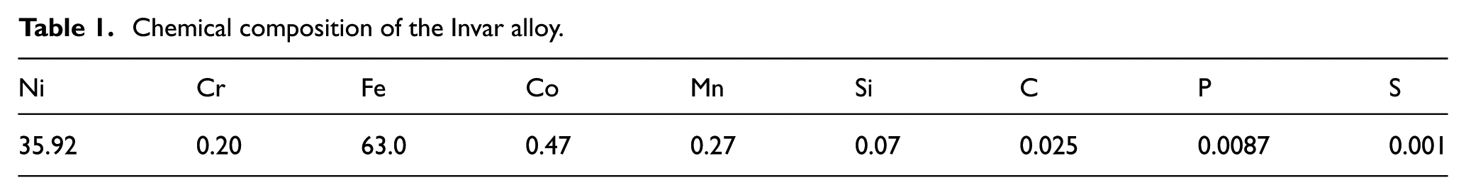
Chemical composition of the Invar alloy.
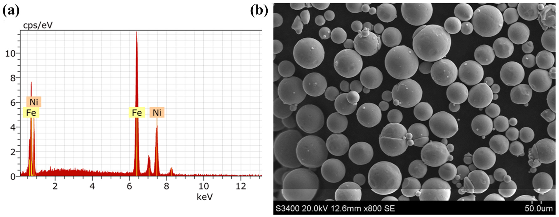
Elemental composition and morphology of the Invar alloy powder: (a) elemental composition measured via energy-dispersive X-ray spectroscopy (EDX) and (b) morphology of the Invar alloy powder.
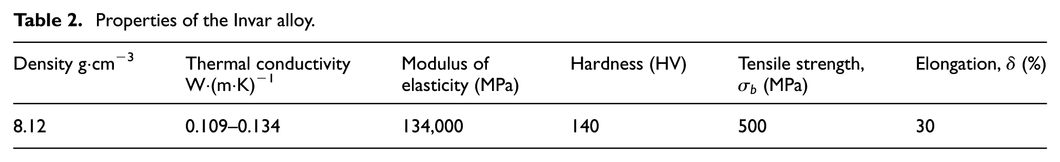
Properties of the Invar alloy.
Experimental equipment
The laser cladding equipment consists of a laser cladding system with a 6-kW continuous Nd:YAG laser (TRUMPF, Germany), a lateral powder feeding system, an XYZ-rotation CNC system, and an atmosphere control system, as shown in Figure 2(a).
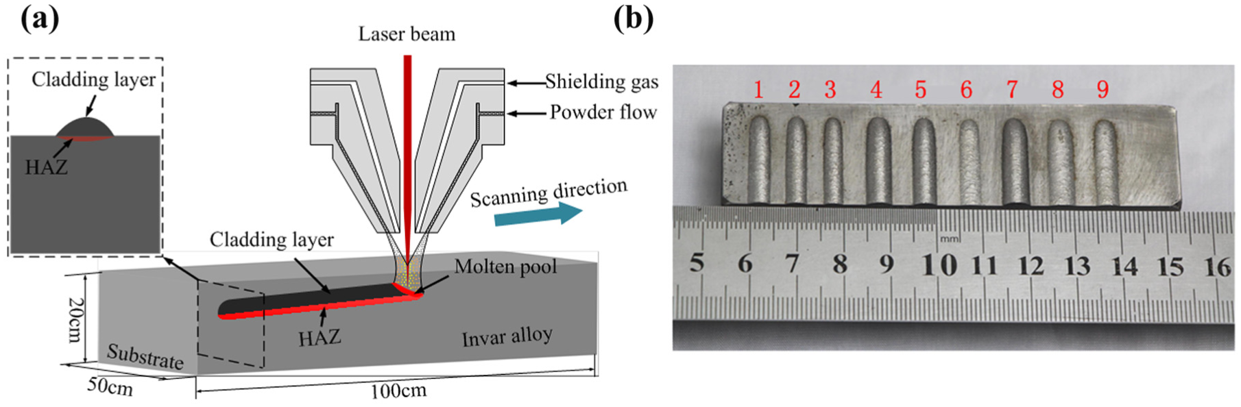
Single pass and single layer of laser cladding: (a) schematic diagram of the laser cladding process and (b) laser clad specimens.
After the cladding experiments, transverse cross-sections were cut from each cladding layer and were then ground and polished by a polishing machine. Next, the microstructure of the cladding layer was analysed by a Leica DMILM metallographic microscope, as presented in Figure 2(b). Data on the geometrical feature of the cladding layer were obtained using a non-contact optical profiler (Sensofar, Spain) that uses white-light interferometry to extract the width, height, and cross-section profile of the cladding layer.
Experimental methods
Because the laser cladding repair was conducted by overlapping and adding layers, the quality of every single cladding layer was very important. In this research, the laser power, scanning speed, and powder feeding rate were chosen as the optimisation parameters. The optimal process parameters were determined by analysing the morphology and microstructure of the cladding layer.
Since Invar alloy rusts easily, temperature and humidity have a large effect on the Invar alloy. First, the oxygen layer on the surface of the substrate was removed using the CNC machine, and subsequently, cleaning and drying were performed. Next, to prevent the oxidation of the powder, the powder and substrate were placed into a sealed device during the cladding using argon as a protective gas. The argon flow rate was 15 L/min. Prior to the cladding process, to exhaust the air, the shielding gas was vented for approximately 30 min. In addition, the laser beam was defocused on the workpiece, which resulted in a laser beam spot diameter of 5 mm. The processing parameters of the cladding experiment are shown in Table 3.
Processing parameters and experimental results of the laser cladding of the Invar alloy.
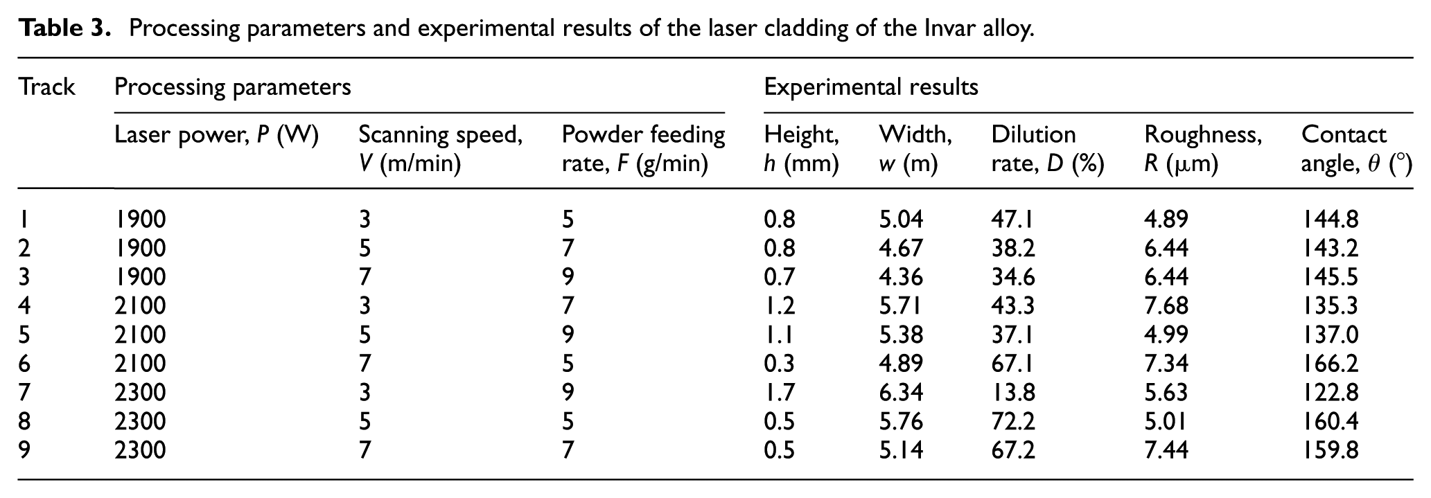
After the completion of the cladding, nine single cladding passes were cut transversely from the cross-sections and then ground, polished, etched, cleaned, and dried. The corrosive liquid was a mixture of hydrochloric acid and nitric acid at a volume ratio of 3:1. The following five characteristics of the cladding layer were selected for the optimisation: h (mm) is the height, w (mm) is the width, D is the dilution rate, R is the roughness, and
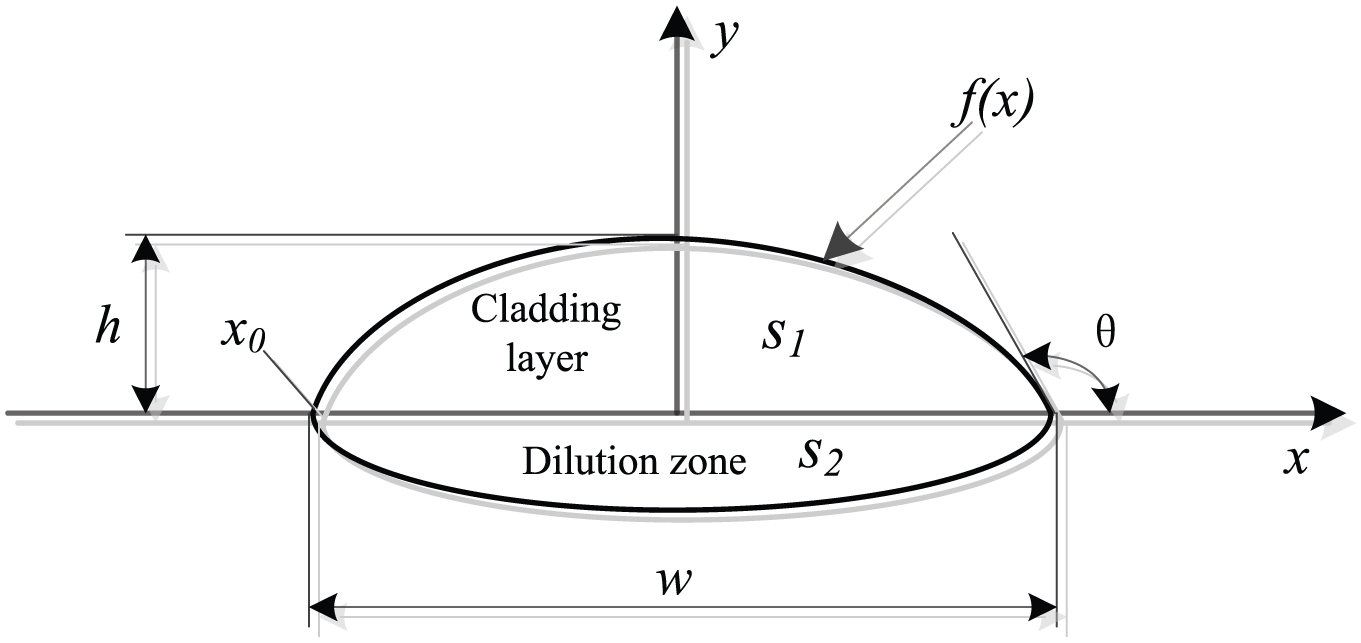
Schematic diagram of the geometric features of the cladding layer.
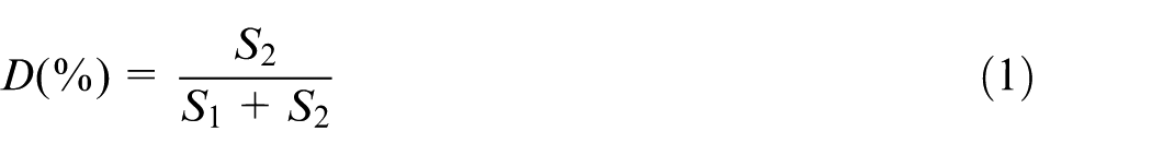
Dilution rate D(%) is given as
where
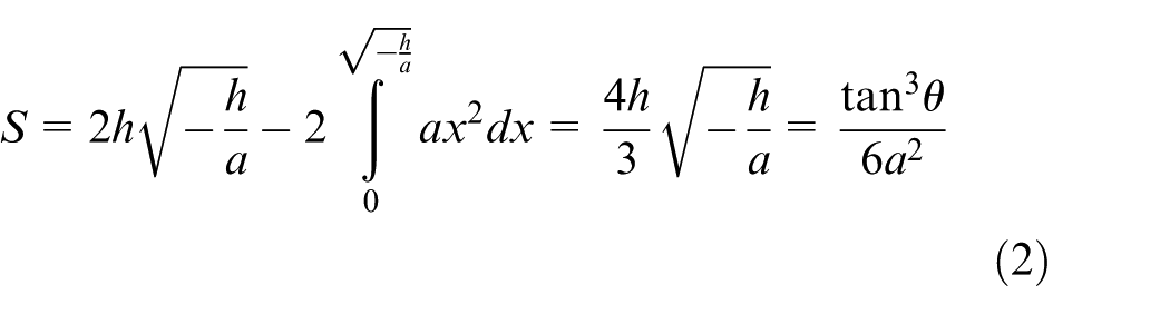
The area of the cladding layer is determined as follows: first, the surface profile data of the cladding layer are extracted by non-contact measurements; next, the curve is determined using these points; finally, the curve equation is obtained and the melting area of the cladding layer can be calculated using equation (2).
The melting depth and width of the substrate derived from the metallographic microscope measurements are used to determine the melting area of the substrate as defined in equation (2)
The contact angle

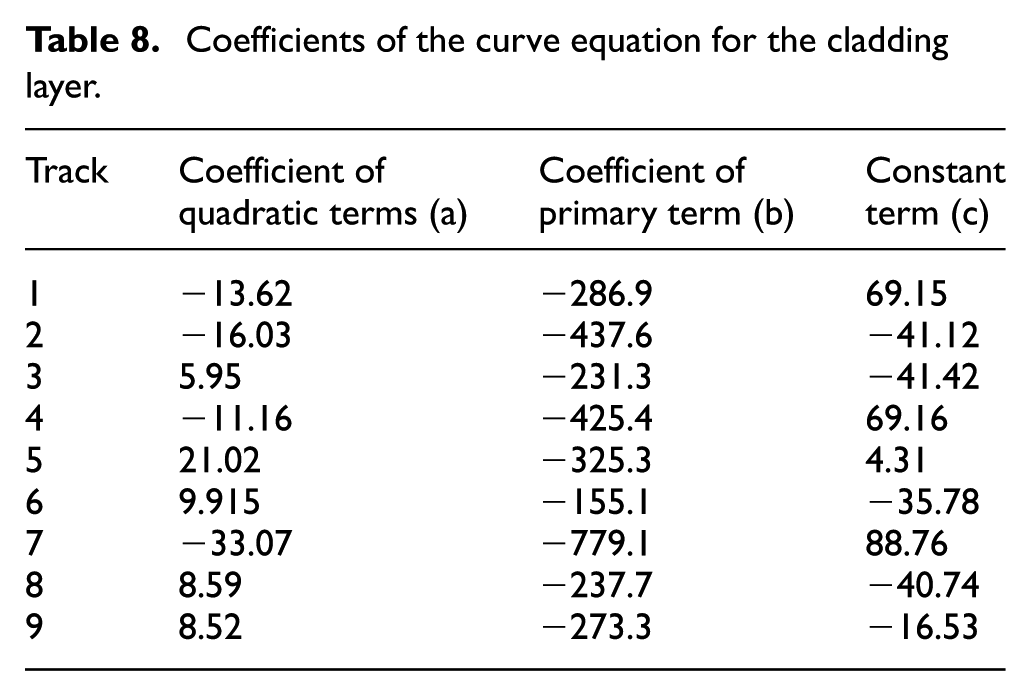
where S is the area of the cladding layer or the melted substrate, f(x) is the profile curve equation of the cladding layer, x0 is the point of intersection between the curvilinear equation and the substrate, the contour curve equation of the cladding layer is f(x) = ax 3 + bx2 + cx + d, where a, b, c, and d are the coefficients.
Morphological analysis
Analysis of the width and height of the cladding layer
When the Invar alloy mould is repaired by the laser cladding process, a smaller width increases the number of single passes and a lower height increases the number of single layers. The powder particles with a larger width and height do not melt easily. Thus, an appropriate width and height of the cladding layer not only reduces the number of single passes and single layers but also improves the repair efficiency and ensures the quality of the cladding layer. The experimental results of the single pass and single layer are shown in Figure 2 and the cladding parameters in Table 3 are used.
Figure 4 illustrates the measurements of the height and width of the cladding layer. The geometric features of the cladding layers were measured using a non-contact optical profiler. The result of a single-pass cladding layer with a height (dz) of 0.8 mm and a width (dL) of 5.0368 mm is shown in Figure 4(a) and (b), respectively. The measurement results of the other eight groups are shown in Table 3. The maximum and minimum heights are 1.67 and 0.31 mm, respectively; the maximum and minimum widths of the cladding layer are 6.34 and 4.67 mm, respectively. Appropriate width and height dimensions correspond to higher quality cladding layers. The widths of the fourth, fifth, seventh, and eighth group are more satisfactory than those of the other groups. The heights of the fourth, fifth, and seventh group are better than those of the other groups. Moreover, the quality and morphological characteristics of the melted cladding layers are excellent.
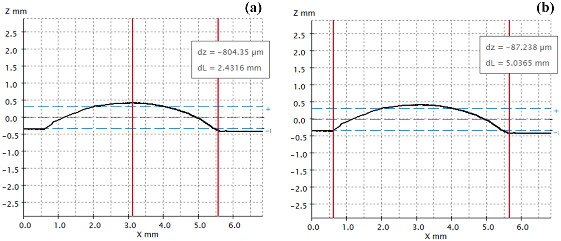
Geometric characteristics of cladding layer: (a) height measurements of the first group and (b) width measurements of the first group.
According to the results of the orthogonal test (Table 3), the influences of the laser power, scanning speed, and powder feeding rate on the width of the cladding layer were analysed. An orthogonal method was adopted for the experiment and a range analysis was adopted for analysing the data. Equations (4)–(6) were used for the calculations
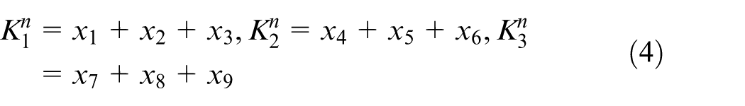
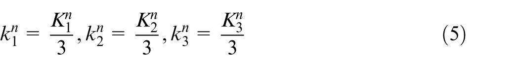

where xl is the width, height, dilution rate, roughness, or contact angle of the cladding layer (l = 1, 2, …, 9);
The
Factors influencing the cladding width.
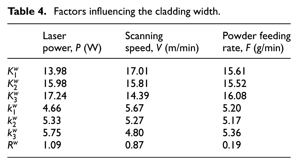
As the powder is blown out from the nozzle onto the substrate during laser cladding, it absorbs heat, melts, and covers the width of the cladding layer. As a result, the width of the cladding layer is generally less than or equal to the spot diameter. If the scanning speed is lower, the accumulation of laser heat will increase the width of the cladding layer. If the scanning speed is higher, the width of the cladding layer will decrease. When the laser power is constant, the width of the cladding layer decreases as the scanning speed increases. The scanning speed was 3, 5, and 7 m/min and the laser power was 1900 W; the resulting widths of the cladding layers were 5.04, 4.67, and 4.36 mm. Similarly, when the laser power was 2100 and 2300 W, the width of the cladding layer was consistent with the scanning speed. According to the energy distribution of the heat source model shown in Figure 2(a), the width of the cladding layer is determined by the radius of the laser light source. When the scanning speed decreased, the powder at the edge of the source was melted by absorbing heat continuously and the width of the cladding layer increased. In contrast, when the scanning speed was constant, the width of the cladding layer increased as the laser power increased. At a scanning speed of 3 m/min and laser powers of 1900, 2100, and 2300 W, the corresponding widths of the cladding layer were 5.04, 5.71, and 6.34 mm, respectively. Similarly, when the scanning speed was 5 and 7 m/min, the change in the width of the cladding layer was proportional to the change in the laser power. Because the light source radius was constant, the width of the cladding layer increased as the laser power increased. Moreover, the powder at the edge of the source melted continuously by absorbing heat.
The
Factors influencing the cladding height.
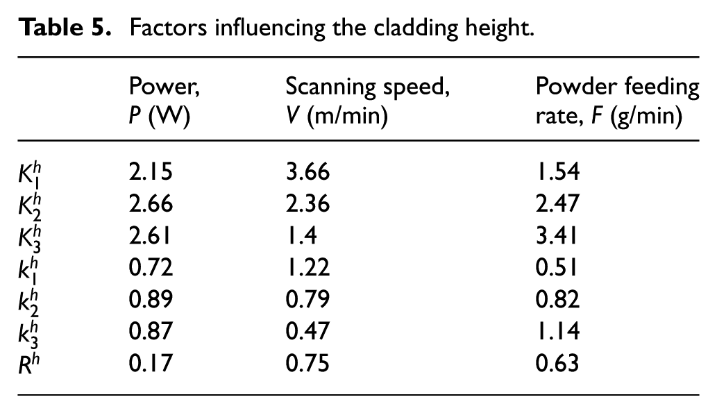
Thus, in the laser cladding repair process, if a larger width is desired, the laser power should be adjusted first. If a greater height is desired, the scanning speed and powder feeding rate should be adjusted.
Analysis of the dilution rate
The dilution rate is an important parameter for measuring the performance of laser cladding repair. A smaller dilution rate will result in low-strength metallurgical bonding between the substrate and the cladding layer, which in turn will weaken the mechanical properties and possibly cause the cladding layer to chip off. A higher dilution rate will result in a larger HAZ and even cause large deformation and cracking of the substrate. Therefore, an appropriate dilution rate is important for the quality of laser cladding repair. Generally, a dilution rate of 8%–15% is suitable.25–27
The melted area of the substrate has an important relationship with the laser power attenuation. When the powder particles are injected from the nozzle, they pass through the laser beam and reach the molten pool; thus, the powder may cover the laser beam such that only a small part of the laser energy reaches the base. 28
The laser power attenuation model has the following assumptions:
Powder particles are uniform and spherical with a radius of r;
Powder particles do not overlap in the laser beam;
Reflection, diffraction, and scattering of the powder particles are not considered;
Laser energy is uniformly distributed.
The diagram of the laser power attenuation is shown in Figure 5(a) and a schematic diagram of the interaction between the particles and the laser is shown in Figure 5(b).
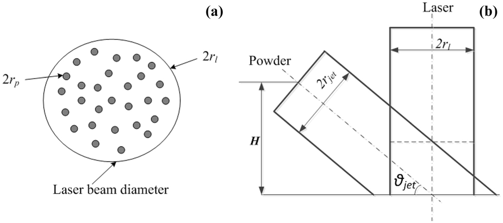
Schematic diagram of the interaction between the particles and the laser: (a) laser power attenuation and (b) interaction between particles.
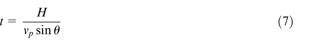
The laser power attenuation is deduced using equations (7)–(14). The time t required for the particles to eject from the nozzle to the substrate is as follows
The quality of the ejected powder of the nozzle is as follows
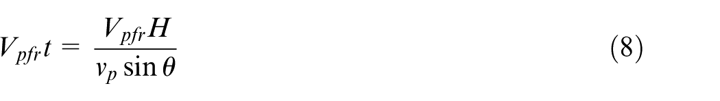
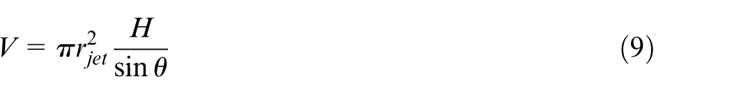
The volume V of the powder flowing from the nozzle before reaching the substrate is as follows
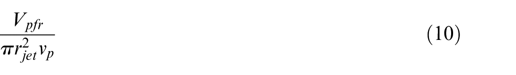
Assuming that the powder is uniformly distributed in space by volume, the powder quality per unit volume is as follows
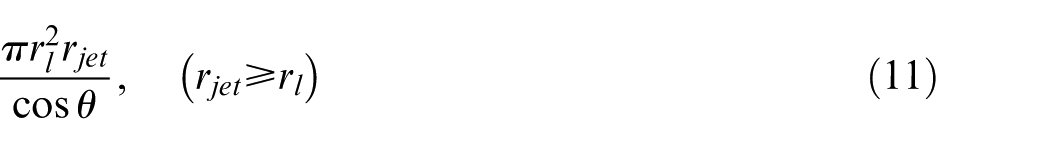
The volume occupied by the powder particles involved in shading during the time t is as follows
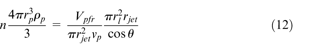
The powder quality involved in the laser power attenuation n is as follows
The area of the powder particles
Therefore, the laser power attenuation is as follows
In these experiments, the particle radius
The measurement results of the dilution rate are shown in Table 3. The minimum dilution rate is 13.8% of the seventh group, as shown in Figure 6(g). The maximum dilution rate of 72.2% occurs for the eighth group as shown in Figure 6(h). Considering the width, height, contact angle, roughness of the cladding layer, and overlap ratio of the adjacent tracks, the seventh group is the best.
Dilution ratio of the cladding layer for nine groups of different processing parameters.
The
Factors influencing the dilution ratio.
Consequently, the powder feeding rate has a direct influence on the laser power attenuation, and a greater powder feeding rate corresponds to greater laser power attenuation, as indicated by equation (12). A higher powder feeding rate increases the area of the cladding layer and shields more of the laser energy. Thus, the substrate absorbs less energy and the melting area is relatively small. In summary, to obtain an appropriate dilution rate and a better metallurgical bonding interface, the powder feeding rate should be given priority to obtain an appropriate dilution ratio.
Roughness analysis of the cladding layer
The surface roughness of the cladding layer also has a great effect on the quality of the cladding layer. In particular, for multilayer, multipass laser cladding repair, the surface roughness directly affects the uniform distribution of the powder on the subsequent cladding layer. In addition, a greater roughness not only affects the surface smoothness of the cladding layer but may also generate pores and result in the collapse of the layers.
In this experiment, the roughness of the cladding surface was measured by a non-contact optical profiler. The measurement results are shown in Table 3, and Ra was selected as the evaluation index of the cladding layer. The roughness values of the first, seventh, and eighth groups are relatively small at 4.89, 5.63, and 5.00, respectively. Figure 7(a) shows that the surface of the cladding layer is not smooth and exhibits large fluctuations, which impacts the uniform distribution of the powder on the subsequent cladding layer. Gaps and cracks may occur in a multilayer cladding process. Figure 7(b) shows that the surface has less damage and the influence of the multilayer coating on the uniform distribution of the powder is relatively small.
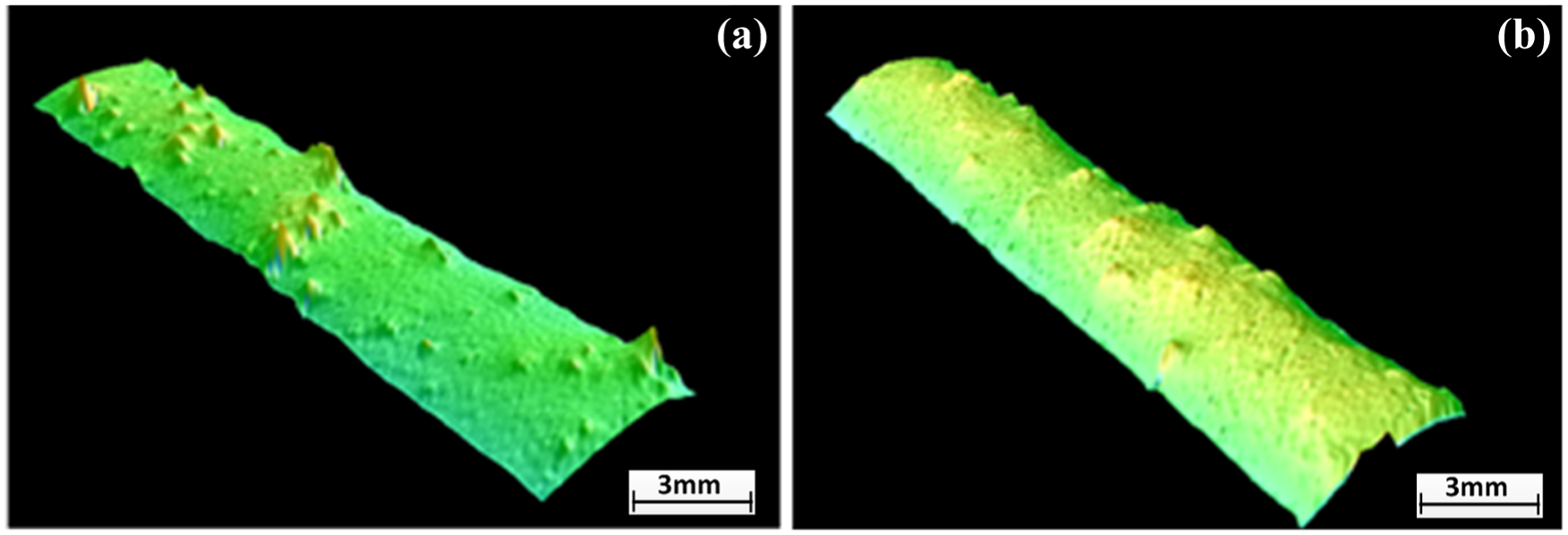
Roughness of the cladding layer: (a) the forth Roughness of the cladding layer and (b) the first Roughness of the cladding layer.
The values of
Factors influencing the roughness.
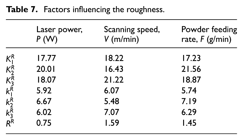
During the cladding process, the powder stream is ejected from the nozzle and reaches the substrate when the laser was irradiated. A certain amount of powder particles produce a molten pool on the surface of the substrate. A large temperature gradient forms on the free surface of the weld pool, which leads to a change in the surface tension that drives the flow of liquid metal by the combined action of the surface tension and the shear stress. Moreover, the convection in the pool has a great influence on the shape, size, surface waviness, and density of the cladding layer. Consequently, the appropriate scanning speed allows the molten pool to have sufficient time convection and results in lower roughness and better cladding quality.
Contact angle analysis of the cladding layer
An important parameter for multipass laser cladding is the contact angle, which affects the wettability of the cladding material and substrate material. Moreover, the selections of the laser cladding parameters are appropriate for determining the contact angle. The contact angle has a direct impact on the quality of a multilayer repair. Research has shown that the contact angle is optimal between 120° and 150°; otherwise, gaps will form between the layers, which may induce the initiation and propagation of cracks.
The points of the surface profile of the cladding layer were scanned and collected using a non-contact optical profiler and were then fitted using a third-order equation in MATLAB. The equation for the cladding layer is f(x) = ax2 + bx + c, and the profile of the curve is shown in Figure 8. The coefficients a, b, c, and d are shown in Table 8. In order to solve for the contact angle, the derivative for the equation f(x) is obtained and the x0 point of the intersection of the curve and the substrate is substituted into equation f(x). Finally, the value of the contact angle is obtained using f(x0), in equation (2). The results for the contact angle are shown in Table 9; the maximum value is 166.2° and the minimum value is 122.8°. The contact angles of the fourth groups and the seventh groups are 135.3° and 122.8°, respectively, which represent the most suitable values. The surface roughness is better when the multiple layers overlap.
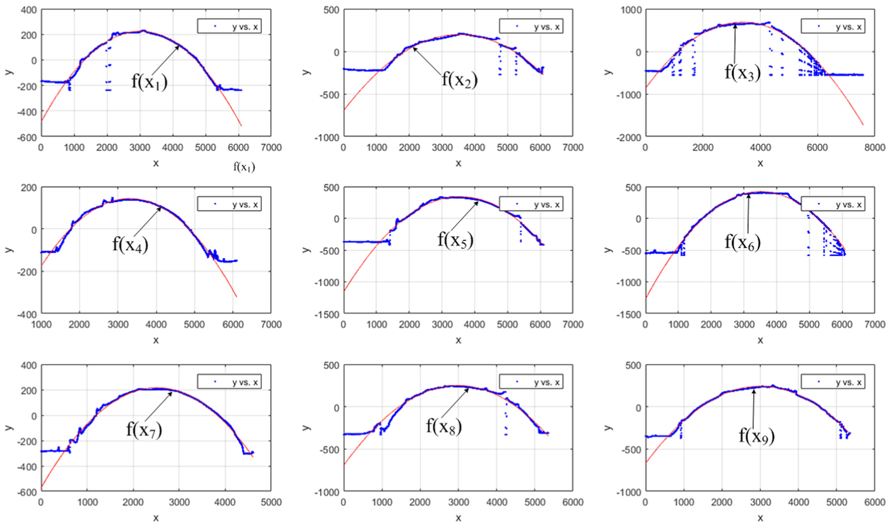
Fitted curves for the cladding layer.
Coefficients of the curve equation for the cladding layer.
Factors influencing the contact angle.
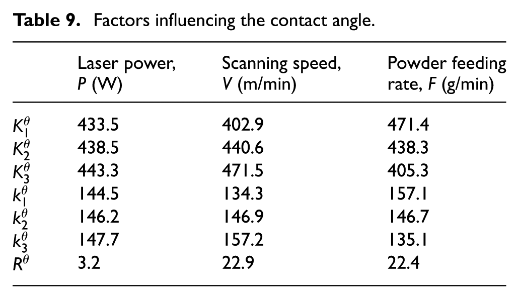
The values of
Microstructure analysis of the cladding layer
Figure 9 shows the microstructure of the Invar laser cladding layer. As shown in Figure 9(a), the microstructure of the cross-section can be divided into three distinct regions, namely, the cladding layer, the HAZ, and the base material. The HAZ layer exhibits coarse grains and a disorganised structure because of the low heat conductivity of the Invar alloy and the high energy density of the laser. A typical martensitic structure is observed with a small amount of austenite and ferrite residues in the HAZ. The observed grain morphology exhibits the unique sub-crystalline structure of Invar alloys in laser cladding, as shown in Figure 9(b). The sub-grains are much smaller in size than the matrix grains and this feature determines the mechanical properties of the laser cladding. The region above the fusion line is the molten pool of the solid liquid transition region and represents the same region exhibiting the sub-crystalline structure shown in Figure 9(b). The HAZ region is below the fusion line and it does not melt during the laser cladding process. Because of the heat conduction, the grain size in the HAZ region is larger than that of the base. It can be observed that the microstructure of the cladding layer in the cross-section resembles a cytoplasm. Moreover, the grain morphologies in the central section of the cladding layer resemble late-forming crystals and the growth direction of these crystals is perpendicular to the fusion line. Compared to the base metal, the grain size of the cladding layer is small, which is caused by the rapid heating and rapid cooling of the laser cladding.
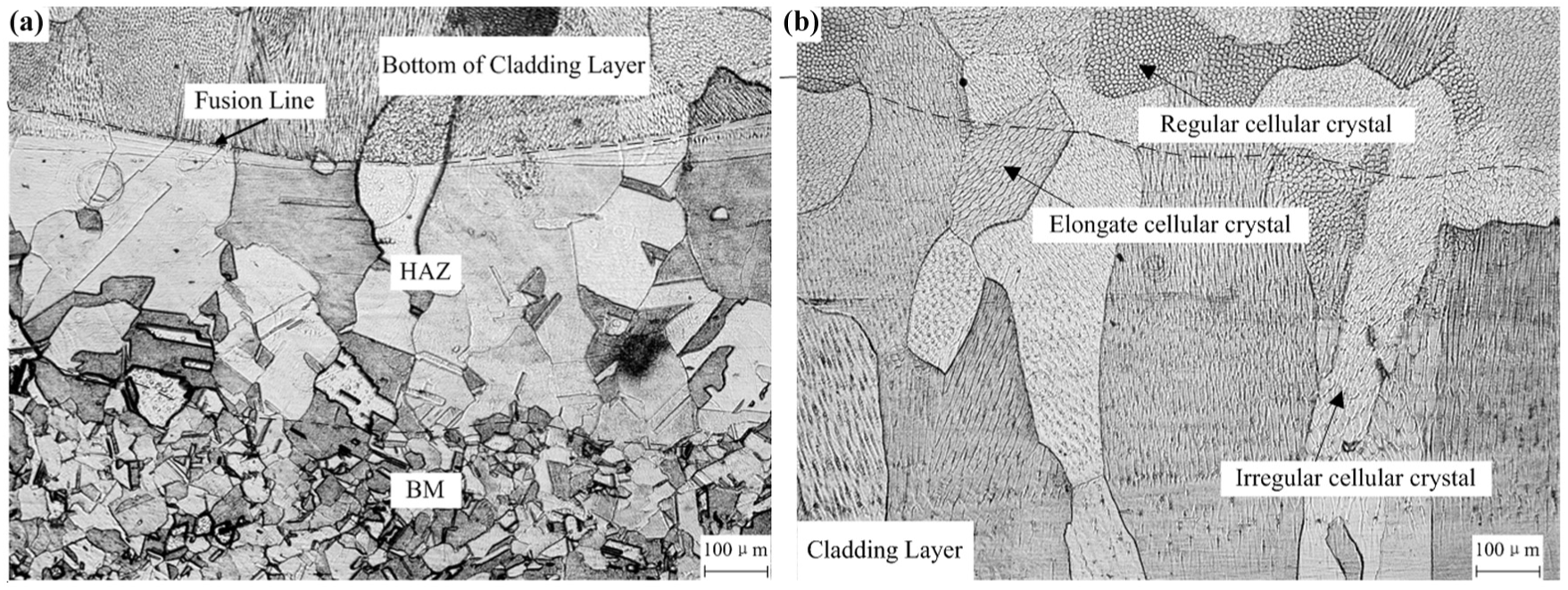
Microscopic characteristics of the seventh group of cladding layer: (a) HAZ of the cladding layer and (b) melting zone of the cladding layer.
The difference in the crystal morphology in the different regions of the cladding layer is determined by the super-cooling degree of the liquid phase composition
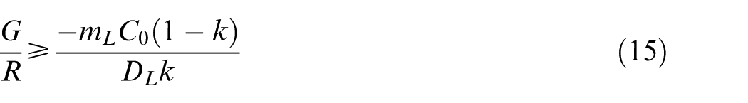
where G is the temperature gradient of the liquid phase, R is the solidification rate, mL is the liquids’ slope in the alloy phase diagram, C0 is the mass fraction of the solute, k is the coefficient of the solute distribution, and DL is the distribution coefficient of the solute in the liquid phase. In particular, G, R, and C0 are the dominant factors influencing the crystal morphology in the cladding layer. The critical condition of the constitutional super-cooling is as follows
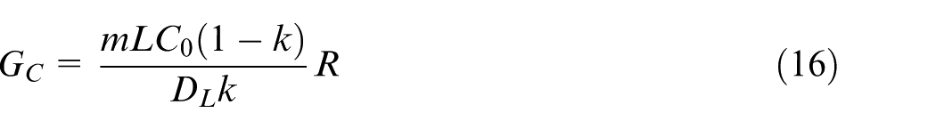
Constitutional super-cooling occurs when G ⩾ GC. The temperature gradient of the solid–liquid interface is closely related to the heat input and heat dissipation. At initial solidification, the solidification rate near the fusion line in the front end of the solid–liquid interface is almost zero because of the contraction of the liquid metal and the base metal. At this moment, the value of GC is very small and the liquidus temperature gradient of G is much greater than that of GC; therefore, no composition undercooling occurs. The grain growth occurs in the form of planar crystals via the non-constitutional super-cooling. However, the duration of growth is very short, making the growth almost invisible.
As the solidification progresses, irregular cellular crystals are formed via the sharp increase in the solidification rate. In the centre of the cladding layer, the constitutional super-cooling is subsequently increased by the enrichment of solute atoms in the front of the solid–liquid interface. The sub-grains are changed to elongated cellular crystals. Moreover, the sub-grain orientation of the elongated cellular crystal is different because of the different temperature gradient, thus leading to a different formation during the organisation at room temperature.
However, the sub-grain microstructures in the top of the cladding layer are different as shown in Figure 9(b). Fine regular cellular crystals are formed in these areas with disorderly directions. The cooling method is mainly caused by the environment in the near-surface liquid metal solidification. It is accepted that the temperature difference between the environment and the liquid metal is large, which results in a higher solidification rate and a lower level G/R value. The sub-grain refinement is caused by these effects. In addition, the cooling direction is not perpendicular to the solid–liquid interface. Therefore, the columnar growth direction is not disordered.
In the cladding experiment, the quality of the cladding is determined by the properties of the cladding layer. The width of the HAZ is a fundamental but quite important index for estimating the results of the experiment. The morphologies of the HAZ are shown in Figure 10.
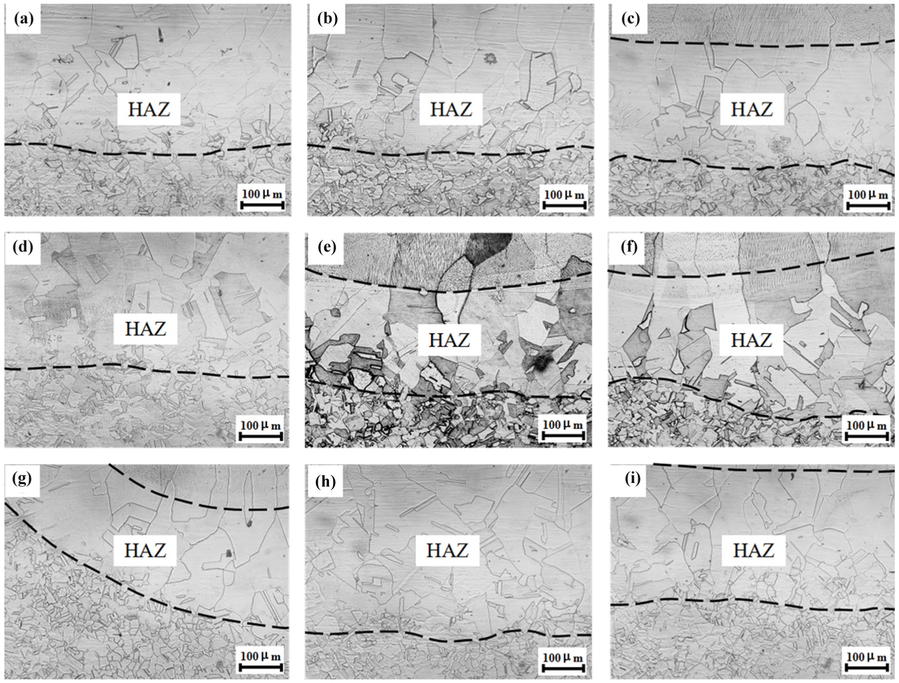
HAZ morphology of the cladding layer for nine groups of different processing parameters.
The results show that the narrowest HAZ is obtained at a laser power of 2300 W, a scanning speed of 3 m/min, and a powder feeding rate of 9 g/min (Figure 9(g)). Although the high laser power results in a high heat input, the inhibiting effect is caused by a decrease in the scanning speed and an increase in the powder feeding rate, which lead to a narrower width of the HAZ. Moreover, the height of the cladding increases and the contact angle decreases via the complete melting of the powder.
Conclusion
In this study, the effects of different processing parameters on the characteristics of the cladding layer were investigated. The following conclusions are drawn:
At a laser power of 2300 W, a scanning speed of 3 m/min, and a powder feeding rate of 9 g/min, the best results of the width, height, dilution rate, roughness, and contact angle of the cladding layer are obtained. Moreover, pores or cracks are not observed.
The laser power has the greatest influence on the width with an
The microstructure of the cladding layer is affected by the super-cooling degree of the liquid–solid interface. The grains are transformed from irregular grains to regular grains from bottom to the surface of the deposition layer due to the change of super-cooling degree. In addition, the maximum temperature gradient is perpendicular to the liquid–solid interface and the grain growth also has a typical orientation along the direction of maximum temperature gradient.
Footnotes
Declaration of conflicting interests
The author(s) declared no potential conflicts of interest with respect to the research, authorship, and/or publication of this article.
Funding
The author(s) received no financial support for the research, authorship, and/or publication of this article.