
Abstract
The development of more sustainable material solutions and the reduction of CO2-emissions in the production phase is one of the biggest challenges in current vehicle design. An approach to meet these requirements is the usage of renewable raw materials. Wood has excellent specific material properties comparable to aluminum and a negative CO2-footprint as CO2 is stored during growth. The usage of timber for vehicle structures has already been investigated in previous projects and certain disadvantages of wood were identified. Compared to metals the elongation to fracture is low causing a brittle material behavior. Another effect is an increasing load level for compression due to compaction. In the project “SuMatHrA” the usage of a timber-steel-hybrid material for a side sill reinforcement of a battery electric vehicle is investigated. The current design of this component for different car brands is an extruded aluminum profile. The main function of this component is to protect the battery during a side crash. The lightweight wood Albasia with a density of approximately 0.3 t/m³ was used for this project. The wood was processed to laminated veneer lumber (LVL) and hybridized with a thin steel sheet. The load was applied in fiber direction causing a crushing of the LVL. To validate the developed hybrid material an aluminum profile from a current production car was used as reference. In quasi static tests it could be shown that the specific energy absorption could be increased by up to 25% compared to the extruded aluminum profile.
Introduction
In recent years it became clear how sensitive our globalized industries react to disrupted supply chains. Therefore, it becomes increasingly important to establish new approaches to guaranty a sufficient supply of raw materials. When it comes to structural materials for the automotive and rail industry the usage of renewable raw materials e.g., wood or fiber materials like flax, hemp or sisal offers multiple benefits. 1 The timber industry offers a big chance to establish new supply chains and bring countries and companies into a completely new market. Furthermore, the usage of wood addresses one of the biggest challenges in current vehicle design which is the reduction of CO2-emissions. Timber has excellent specific material properties which are comparable to typical engineering materials like aluminum. 2 Besides that, considering the carbon storage of the natural material, it has a negative CO2-footprint and can be referred to as environmentally friendly.
In the project discussed in this paper the usage of the lightweight wood Albasia or Sengon (bot.: Paraserianthes falcataria) is investigated. One project partner is a non-profit-organization which supports sustainable reforestation programs in tropic regions e.g., Indonesia. In cooperation with smallholder farmers sustainable plantations combining timber and food corps are created. Not only leading to a reforestation of the areas but also providing a secure income, preserve biodiversity and counteract climate change. Albasia is one of the fastest growing wood species resulting in a yearly growth of 4 m for trees younger than 5 years. 3 As a so-called pioneer tree, the Albasia tree also grows on degraded areas and even improves soil quality due to nitrogen fixation. 3 Besides its ecological benefits the density of approximately 230 kg/m³ - 380 kg/m³ (Section 4) is comparably low. Nevertheless, the compressive strength for high densities is comparable to european soft wood species like Spruce (Section 6.3). 4 Although the mechanical properties are very good, there are also challenges that need to be addressed in the project e.g., wood has scattering material properties, the material properties depend on the moisture content and the temperature and if wood is exposed to water it can start to rot. Some of these challenges will be discussed in the work presented. Nevertheless, further investigations are necessary.
State of the art
In the project, three different use cases for the usage of Albasia wood are investigated. The first use case is an elevator cabin, the second use case is a box body for cargo transport and the third use case is the side sill reinforcement for a battery electric vehicle. In this paper, the use case “side sill reinforcement” will be discussed in further detail. The side sill reinforcement has a very important function when it comes to a side impact. It is necessary to absorb energy during the crash and to avoid a too high intrusion. For battery electric vehicles this task becomes even more difficult. The battery case has a very high stiffness and is not part of the crash structure. It is even required to minimize intrusion into the battery pack to avoid any damage of the battery cells that could lead to a fire. Therefore, it is necessary to absorb the energy during the crash in the side sill while the space available is very limited. This leads to a different design approach compared to a car with combustion engine. By installing an energy absorbing reinforcement in the side sill the energy absorption can be controlled precisely. In the current state of the art extruded aluminum profiles with optimized geometries are used for this purpose (Figure 1).
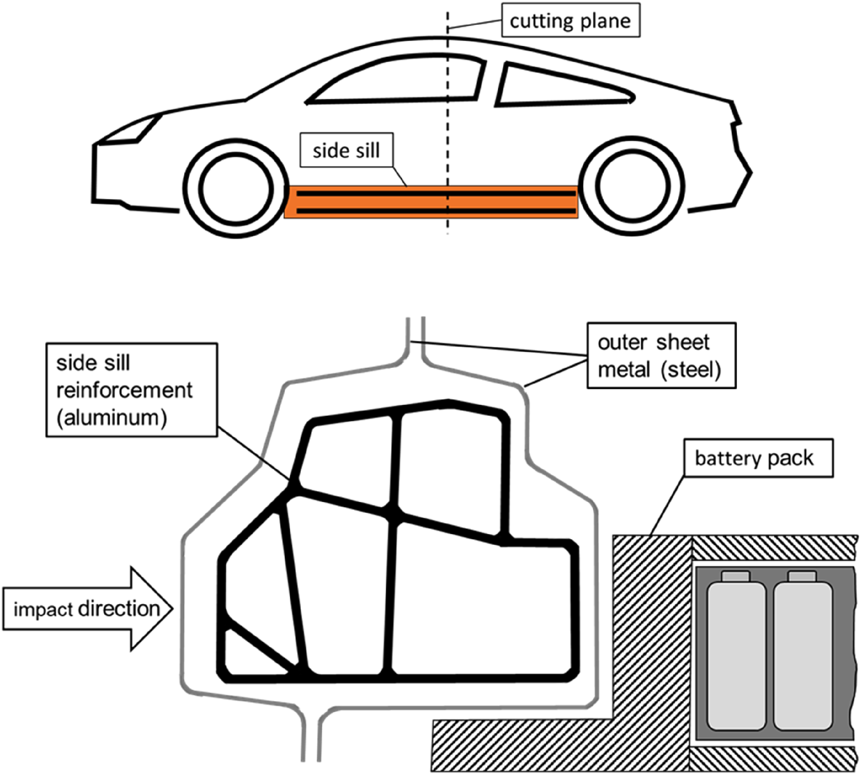
Sectional view of the side sill and battery case in a reference battery electric vehicle.
The crash scenarios especially relevant for the european market are defined by the European New Car Assessment Program (Euro NCAP). There are several different tests performed to rate the crash performance. One test which is especially relevant for the performance regarding side impact is the “side pole” crash. The assumption for this test is a side crash into a rigid cylindric barrier (e.g., a telegraph pole) with a diameter of 254 mm. The car crashes at a speed of 32 km/h with an angle of 15 degree to the pole (Figure 2). 5
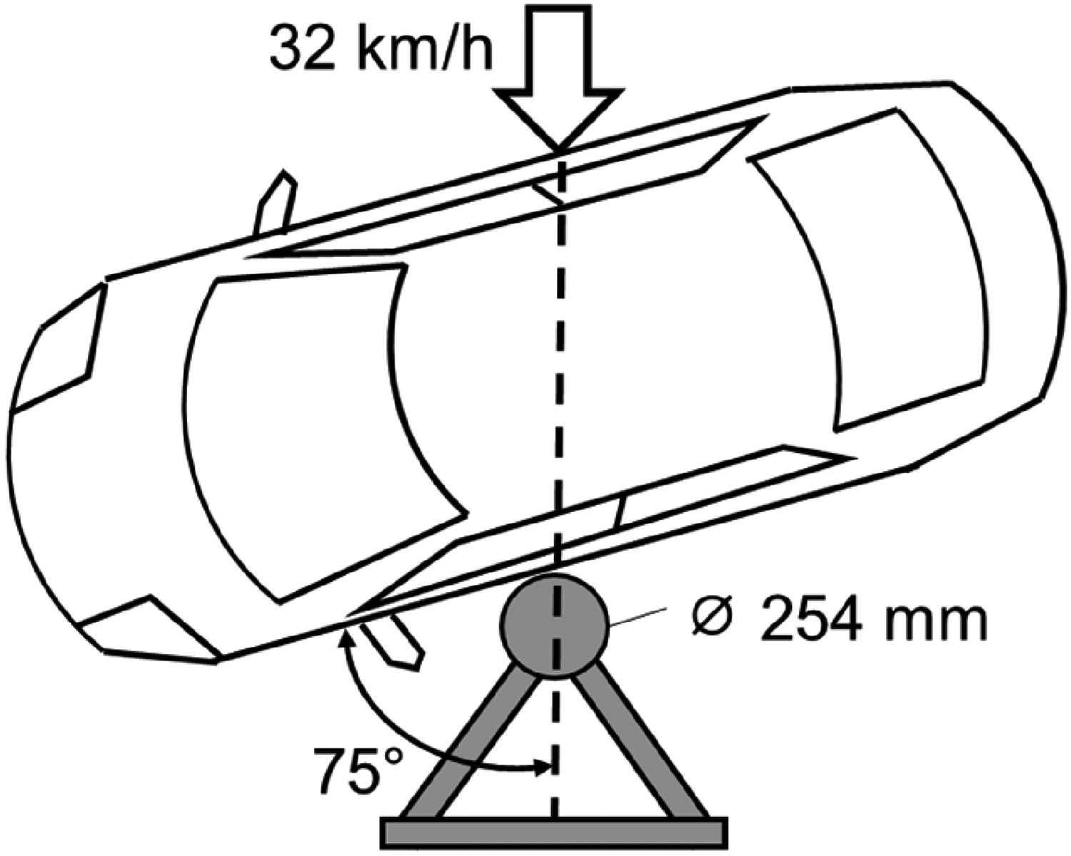
Definition of the “Pole Crash” according to Euro NCAP.
The goal of the project is the substitution of the reinforcement shown in Figure 1 with a structural component made from Albasia and hybridized with steel. The project focuses on the usage of Albasia wood as laminated veneer lumber (LVL). For the production of LVL the trunk is peeled into thin layers (veneers) which are glued together, pressed and cured. This process is highly automated and used for the production of high quantities. The usage of veneer provides multiple advantages. As multiple thin layers are glued together, scattering material properties can be compensated. The fiber orientation of each layer can be chosen according to the load case. By pressing the stack of veneer and glue into a mold it is possible to fabricate three dimensional geometries (with certain restrictions). 6 Nevertheless, there are also challenges that have to be addressed when wood is used in structural applications. The material properties depend on the temperature and humidity of the wood. 7 Furthermore, easy flammability is associated with wood. These disadvantages could be addressed with the component design. The flammability could be significantly reduced by hybridizing wood with steel. 8 By providing a physical wood preservation the risk of wood rot can be eliminated. Further tests addressing the mentioned challenges are part of the project but will not be discussed in further detail in this paper. It is also planned to use simulation models to investigate effects such as ageing, moisture absorption and temperature dependence in more detail.
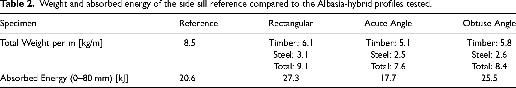
The reference design of the side sill reinforcement (extruded aluminum profile) has a weight of approximately 14 kg. According to 9 the CO2 eq. for aluminum is approximately 5.2–20.0 kg /kg raw material. This would mean that the CO2-emissions for the raw material of the component are between 72.8 kg and 280 kg. The design approach chosen for this paper is focusing on the usage of timber and steel. Unfortunately, there is yet no data available for Albasia. For steel, the CO2 eq. is approximately 1,4 - 4,2 kg /kg raw material. 9 For European hardwood the values for plywood are approximately 0,3–0,7 kg CO2 eq./kg raw material according to. 10 In this calculation the carbon storage effect of wood is not considered. According to Table 1 with a distribution of one third steel and two thirds timber for the component a similar overall weight as the reference could be achieved. Therefore, a reduction of the CO2 eq. emissions could be expected. A life cycle assessment (LCA) is currently being carried out for Albasia as part of the project which will allow a precise analysis.
Weight and absorbed energy of the side sill reference compared to the Albasia-hybrid profiles tested.
The usage of timber in vehicle structures under three-point bending load cases has already been investigated in several projects (e.g., WoodCAR, 11 For(s)tschritt, 8 HAMMER, 12 CARpenTiER). In these projects two disadvantages of timber were identified. Compared to metals the elongation to break in fiber direction (parallel to the grain) is with approx. 0,7–1% very low. 7 Especially for crash relevant components this material behavior is critical as the structure fails abruptly without significant absorption of the crash energy. A second effect is an increasing load level for compression due to compaction. This mechanism is mainly driven by the microstructure of the wood which is different for various wood species and also the reason for the wide density range of wood. With this in mind a new approach for the usage of timber in crash relevant components for vehicle structures was developed. First the crash loads should be applied parallel to the grain causing a crushing behavior of the timber instead of an abrupt failure. Second the density of the timber needs to be high enough to provide a certain load level during compression but low enough to ensure a large displacement without compaction. Third the timber should be hybridized with steel to provide an integration in the vehicle structure, to increase the load level if necessary and to protect the timber from environmental influences.
Experiments
In the work presented a big variety of different tests was performed. The main goal of these tests was a better understanding of the overall material behavior under compressive loading and a validation of concepts to implement the hybrid material in a side sill structure. The compressive tests to analyze the material behavior were divided in two test series. In the first series cubic samples of solid wood were tested these tests followed the standards ISO 13061-5 13 and ISO 13061-17. 14 In a second test series plywood samples with different layups were tested. Therefore, a special test setup oriented on the DIN EN 14126. 15 was chosen. From these tests the compressive strength as a function of the density could be derived. In a next step plywood sheets of different thicknesses were tested in a pole crushing test without hybridization. From these tests, the absorbed energies in crushing were derived and compared to the results of beech plywood. These tests were followed by pole crush tests of plywood with 30 mm and 100 mm thickness hybridized with thin steel sheets. In the final test series, the influence of the cross-sectional geometry on the pole crushing behavior was investigated and compared to the side sill reference structure currently used in series production.
At the beginning of the following sections the tests carried out and the experimental set up are described in more detail.
Compression tests for material characterization of solid wood
Experimental set up
With compression as the main load case for the side sill pole crash test, the main focus of material characterization is the compressive strength of the material. The data available for the material properties of Albasia and especially Albasia plywood is very limited. As already mentioned, first tests indicate a good ratio between compressive strength and density. 16 Nevertheless, further tests are necessary and were carried out in. 8 In a first test series specimens with an edge length of 30 mm × 20 mm × 15 mm made out of solid wood were tested. The specimen dimension are slightly different than in the standard ISO 13061-5 13 due to the limited material availability of Albasia solid wood. The tests were performed with the load being applied parallel and perpendicular to the grain and at a loading rate of 0.1 mm/s. The tests were carried out on a ZwickRoell Universal Testing Machine. For the test with load parallel to the grain, six specimens were tested whereas for the test perpendicular to the grain, 15 specimens were tested. The goal of these tests was to validate the results found in literature. Figure 3 shows the tests with the vector of compression load parallel to the grain (fiber direction 0°) and Figure 4 shows the tests perpendicular to the grain (fiber direction 90°). Especially for the tests perpendicular to the grain the high compressibility which is comparable to foam materials becomes obvious.
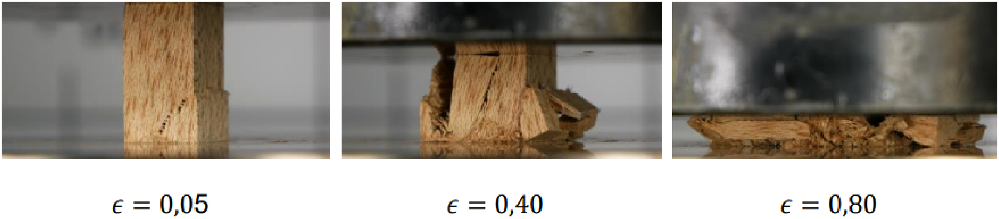
Compression tests of Albasia solid wood parallel to the grain at different strains 17 showing the fracturing of the material.
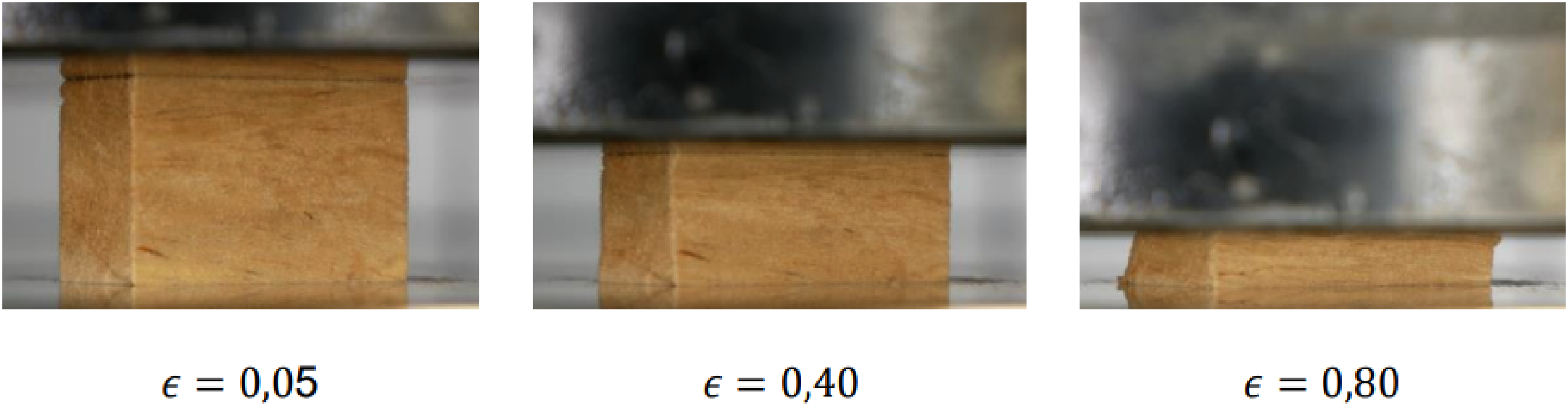
Compression tests of Albasia solid wood perpendicular to the grain at different strains 17 showing the high compactability of the material.
Results and discussion
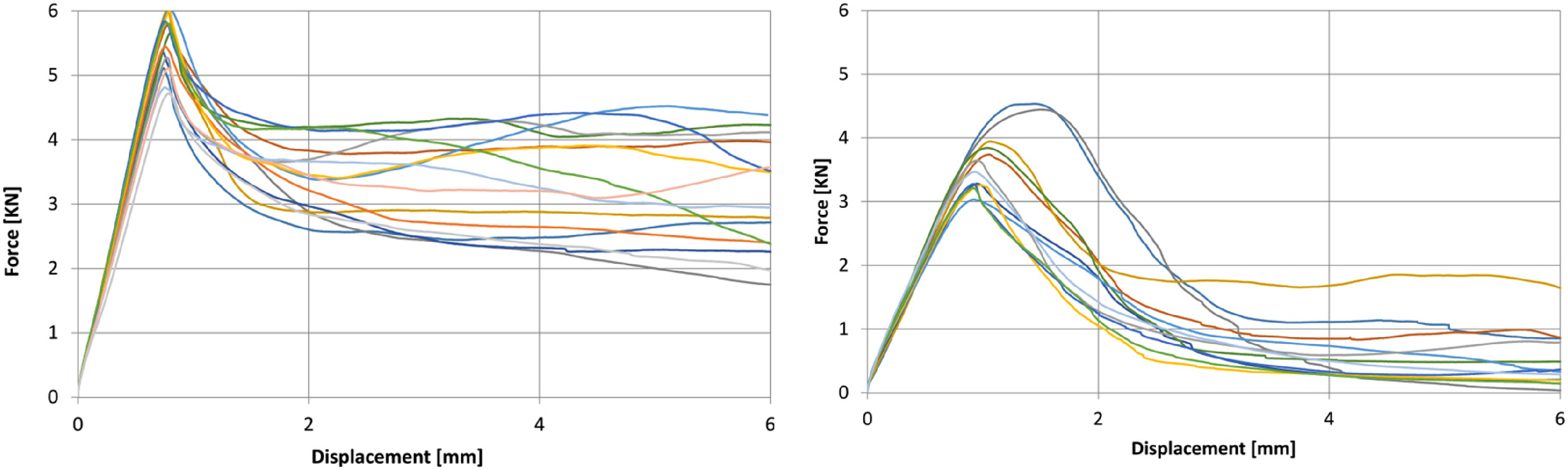
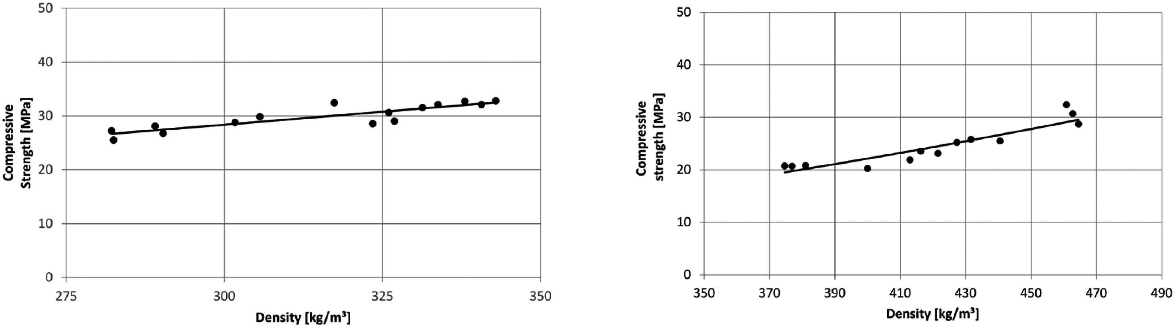
In Figure 5 the results for the tests parallel and perpendicular to the grain are shown in terms of force-displacement curves. The material properties of timber depend on the density. Therefore, the compressive strength is plotted for the different densities measured before testing and shown in Figure 6. The correlation between the density and material properties is in accordance with literature almost linear. 7
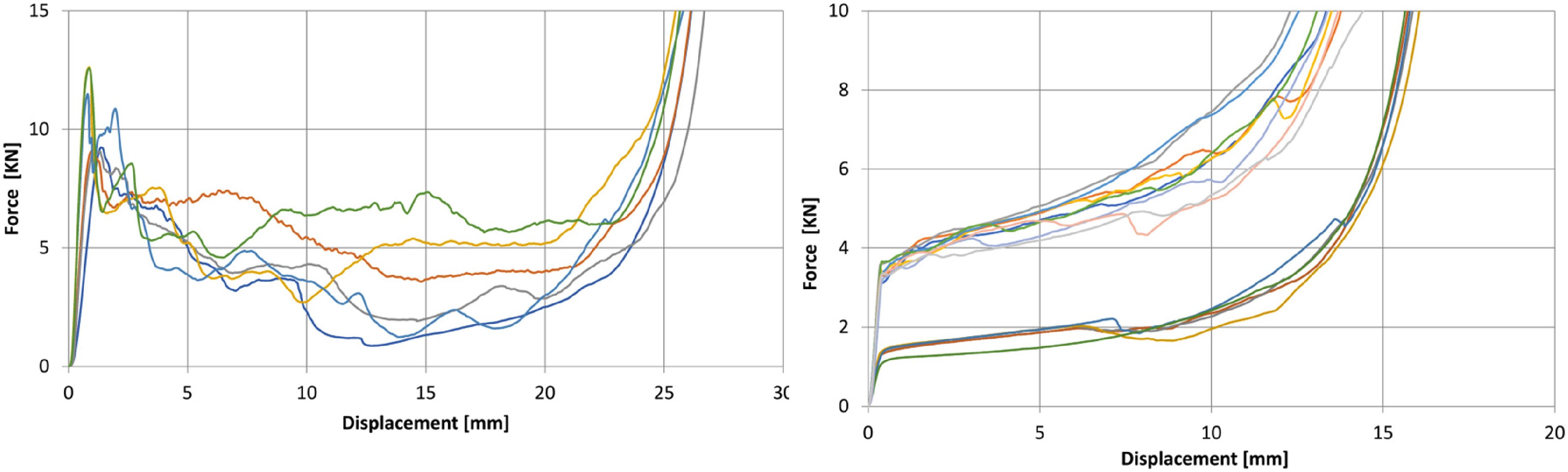
Force-displacement curve of solid wood parallel to the grain (left) and perpendicular to the grain (right) each colored line represents one specimen. 17
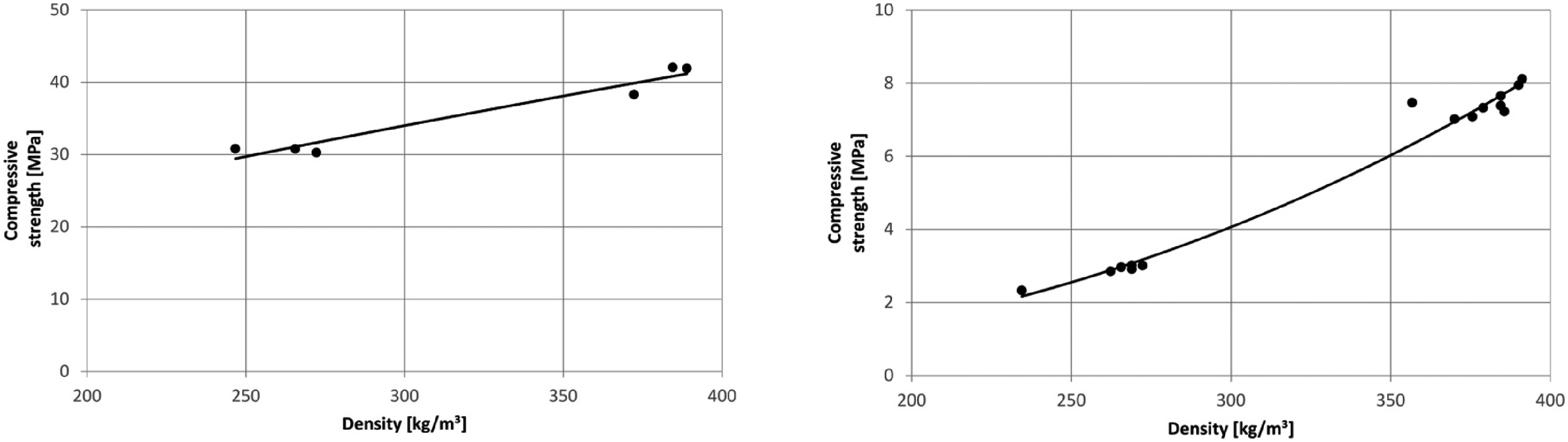
Compressive strength for different densities, results parallel to the grain (left) and perpendicular to the grain (right). 17
The test data shows a wide range of different densities from approximately 230 kg/m³ up to 390 kg/m³. For densities of approximately 380 kg/m³ the compressive strength parallel to the grain direction of 42 MPa is in good agreement with the literature. Nevertheless, for the lowest density the measured compressive strength is reduced significantly to approximately 30 MPa. For the tests performed perpendicular to the grain direction the influence of the density is even bigger, as the strength is reduced significantly. It is shown in the right diagram of Figure 5 that the force-displacement curves are clearly separated in two groups. This shows the significant influence of the density on the compressive strength perpendicular to the grain. Since the specimens were manufactured from different solid wood blocks, the densities of the specimens are grouped between 234 kg/m³ and 272 kg/m³ with compressive strength of 2.33 MPa and 3.01 MPa, respectively and 357 kg/m³ and 391 kg/m³ with compressive strength of 7.47 MPa and 8.12 MPa, respectively. The test results illustrate the wide density range within the same species and the high influence of the density on the material properties. For the use in vehicle structures more uniform material properties are required.
Compression tests for material characterization of LVL
Experimental set up
The properties under compressive load were analyzed for LVL. Two different layups with three 2.5 mm thick layers were investigated. The unidirectional (UD) layup contains of three 0° layers whereas the plywood contains of three layers with a [0°/90°/0°] orientation. For the UD-Layup the veneer layers were glued together using a polyvinyl acetate (PVAc) adhesive (Henkel, Ponal Classic). PVAc adhesives are very common and can be processed easily in a manual process. For the final components other adhesives are considered as the requirements for thermal stability and humidity in the automotive industry are high. For the characterization of different layups, the performance of PVAc is sufficient. In order to provide a high data quality, the humidity and the weight of each layer was measured before the joining process. To make sure that the specimens were cured completely the humidity of the material was also measured after the curing process. After 48 h the specimens were completely dried. The plywood was manufactured in an industrial process using a different adhesive. As the material was stronger compressed during the manufacturing process the density is higher compared to the manually manufactured UD-laminate. Therefore, the results for the compressive strength of the two layups have to be compared for similar densities using the linear correlation. The compression tests were carried out in accordance with the standard DIN EN ISO 14126 originally developed for composite materials and adapted for characterizing LVL (Figure 7). The loading rate of all tests was 0.1 mm/s. The goal of these tests was a direct comparison of the pressure strength of LVL and solid wood. The tests were carried out on a ZwickRoell Universal Testing Machine.
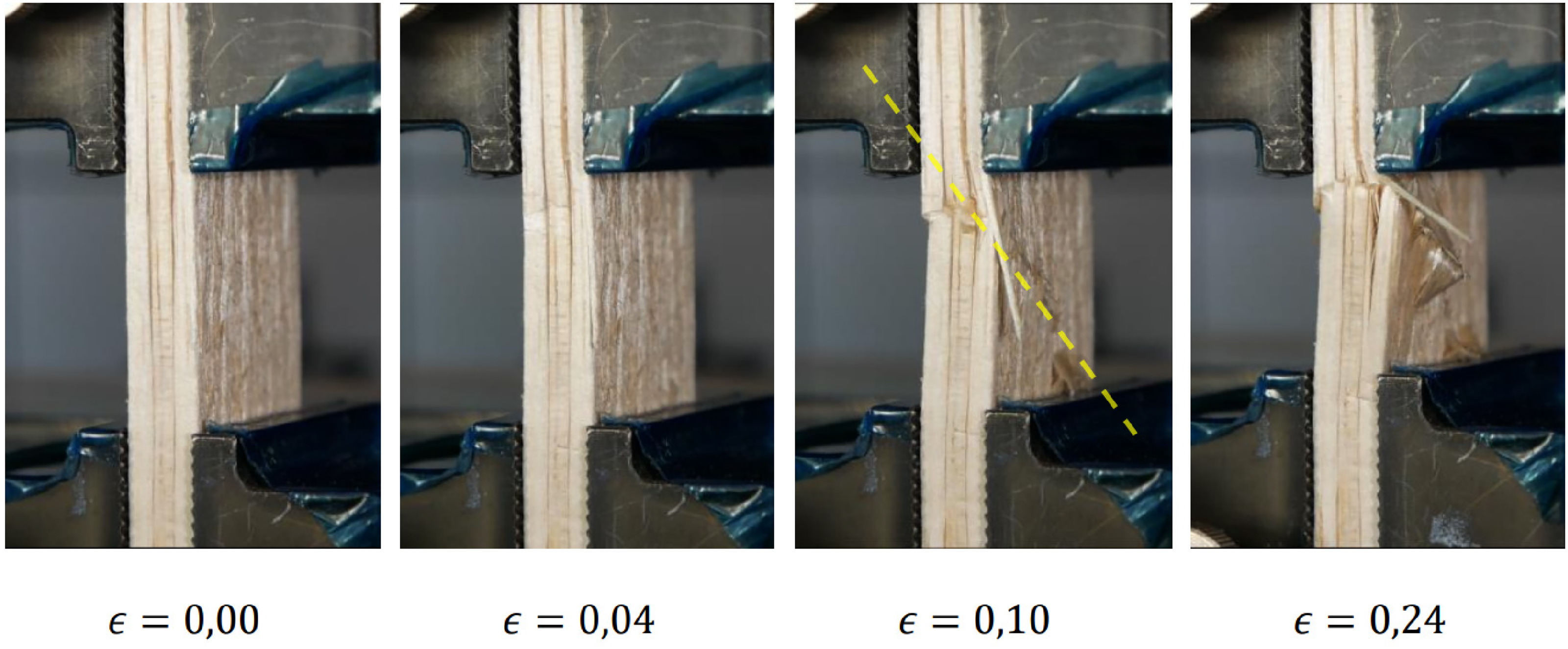
Compression tests for LVL with layup UD [0\0\0] according to DIN EN ISO 14126 for different strains. 17 The yellow dashed line indicates the orientation of the major crack.
Results and discussion
The result of the material characterization tests for the two LVL layups as force-displacement curves are shown in Figure 8. From this, the compressive strength of each tested specimen is calculated. The compressive strengths with respect to the density of each specimen is shown in Figure 9. As seen in Figure 9, the values for LVL are lower compared to solid wood (Figure 6).
Force-displacement curve LVL for UD [0°/0°/0°] (left) and plywood [0°/90°/0°] (right) each colored line represents one specimen. 17
Compressive strength for different densities, results for LVL for UD [0°/0°/0°] (left) and plywood [0°/90°/0°] (right). 17
For the specimens with a unidirectional layup the following reasons were identified for the lower values:
Small cracks caused by the peeling process cause a reduction of the strength of each veneer layer As the layers are thin the risk of buckling is increased As soon as the layers start to delaminate the strength is decreased significantly
For the tests carried out with plywood a further reduction of the material properties is caused by the middle layer as the fiber direction is perpendicular to the compression load. The tests show the influence of the fiber direction and the influence of the density. For solid wood values comparable to literature could be achieved. For LVL a reduction of the compressive strength becomes obvious. The values are within the expected range and are especially relevant for the optimization of the layup like the reduction of 90° layers to increase compressive strength or the substitution of LVL with solid wood.
Compression tests on plywood sheets and profiles without and with hybridization
Influence of material thickness without hybridization
Experimental set up
In order to evaluate the potential of Albasia LVL for the side sill reinforcement plywood sheets with different thicknesses were tested. The specimens were tested at quasi static compressive loading with the test setup shown in Figure 10.
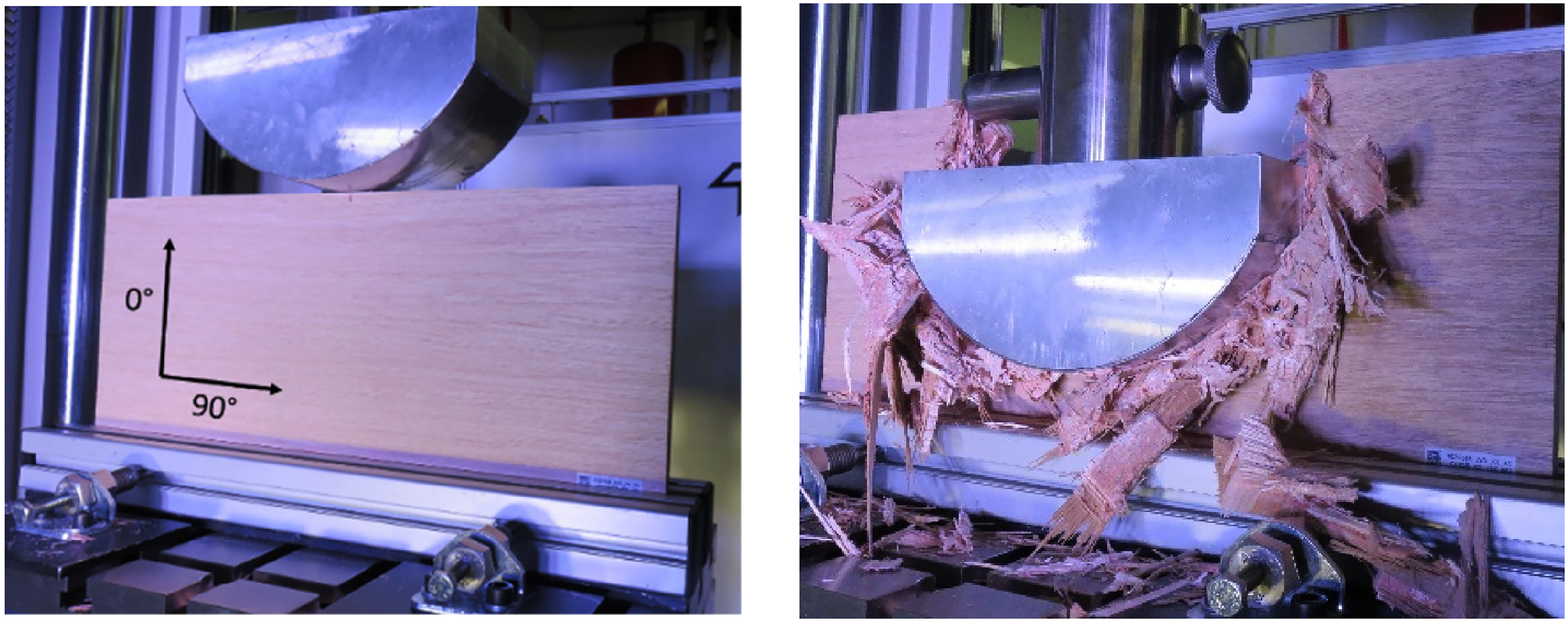
Test setup for pole crush compression tests on Albasia plywood of different thickness. The definition of orientation of the grains is shown left. Crushed plywood plate at the final displacement of 150 mm (right).
In accordance with the boundary conditions for the pole crash mentioned in Section 2, a pole with a diameter of 254 mm was used for the tests. To analyze the material behavior the tests were performed at an 90° angle and not at an angle of 75° (Figure 2) using a ZwickRoell Universal Testing Machine.
Albasia plywood specimens with alternating fiber orientation of 0° and 90° with dimensions of 450 × 225 mm and the three thicknesses of 8 mm, 15 mm and 30 mm were tested with five repetition tests at a quasi-static loading rate of 1 mm/s. In comparison, three specimens made of beech plywood (density of beech wood 700–790 kg/m³ 4 ) with the same dimensions and a plywood sheet thickness of 16 mm were tested. The specimens were clamped at the bottom with aluminum profiles with a height of 45 mm. The maximum intrusion of the pole was 150 mm to achieve a progressive crushing process but to prevent interaction of the LVL debris with the clamping device at the bottom. The goal of these tests was a comparison of different material thicknesses to gain a better understanding of the load level, the load displacement curve and the energy absorption for compression with a pole geometry.
Results and discussion
In Figure 11 the test results for different thicknesses are shown. Details of the specimens are listed in Table 2.
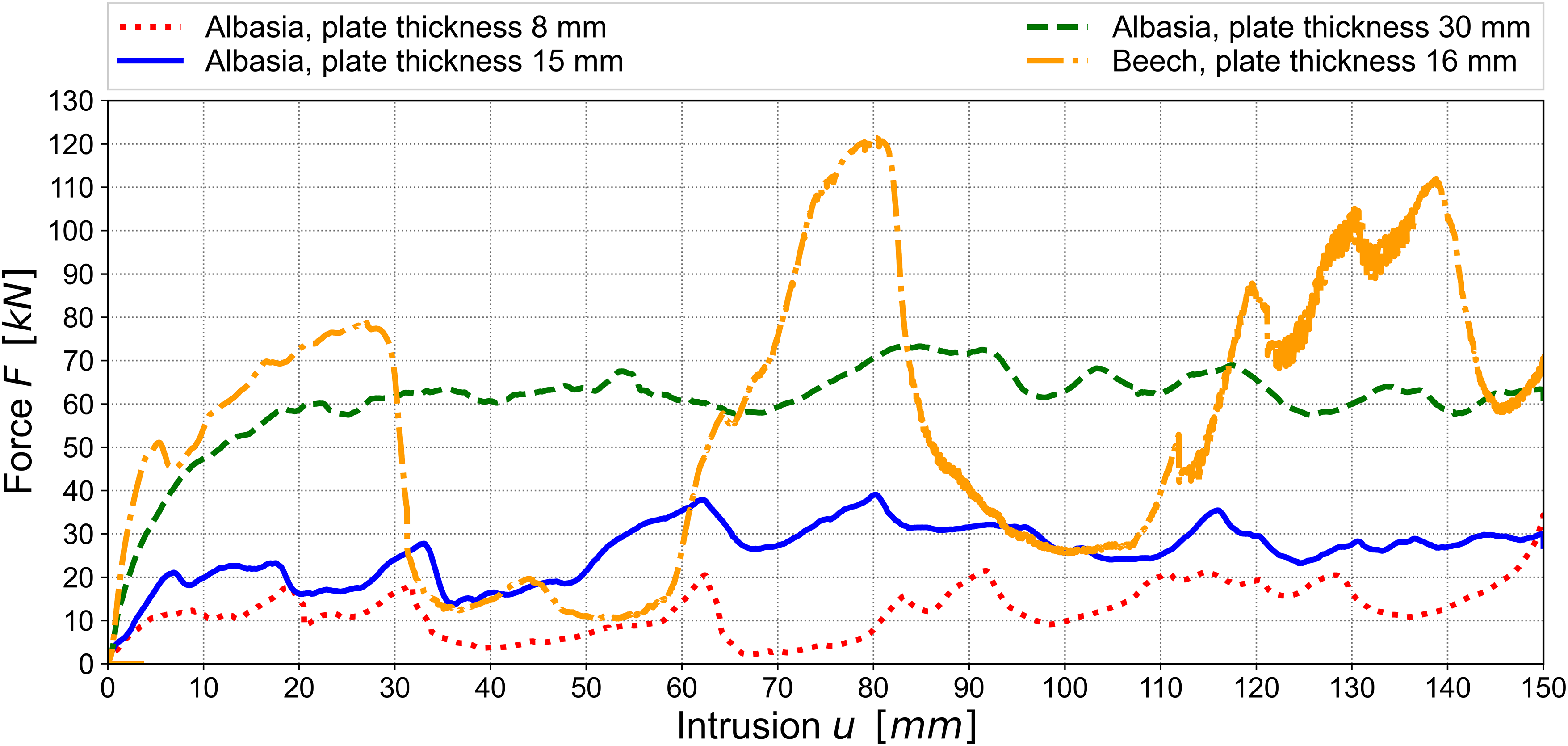
Exemplary force-displacement curve for Albasia plywood of different thickness compared to beech plywood. Specimens without hybridization.
Specimen definition, number of layers and absorbed energy for specimens without hybridization.
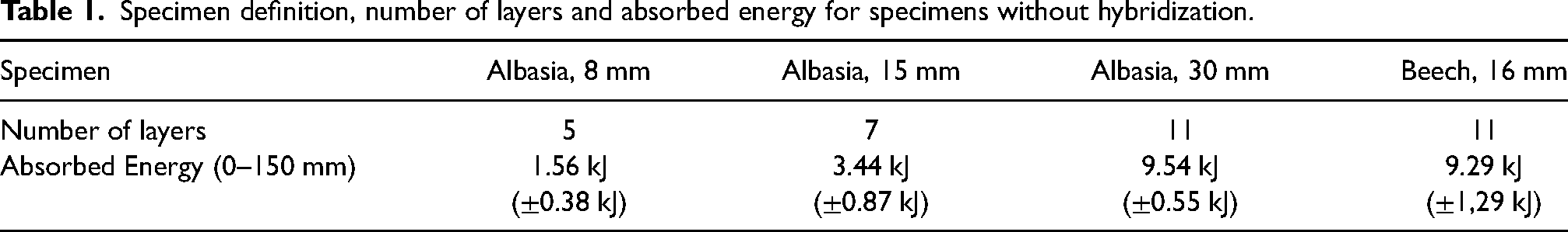
The absorbed energy is calculated as the integral of the force-displacement curve. For crash relevant components absorbing a large amount of energy the goal is a constant load level during the crushing process and therefore a constant level of energy absorption. As it becomes obvious from Figure 11 the load levels for beech plywood varies a lot as the plywood is not compressed continuously. The material behavior of beech plywood is a mixture of compression, delamination and failure of the laminate. In contrast the crushing of Albasia plywood has an almost constant load-displacement curve. The low density of the material leads to a higher compressibility and an almost constant load level over the pole intrusion. The load level increases with increasing material thickness. In addition, the deviations from the mean value are reduced with increasing material thickness. A comparison of the absorbed energy shows that the correlation of the absorbed energy and the thickness is not linear. The amount of material getting compressed in the core of the plywood sheet instead of fracturing at the side increases with the sheet thickness. From Table 2 it could be seen that an increase of the material thickness by a factor of 3.8 (from 8 mm to 30 mm) leads to an increase of the absorbed energy by a factor of 6.1.
Influence of hybridization
Experimental set up
In a next step, the plywood sheets were hybridized with a thin steel sheet. The goal of this hybridization process was to amplify the effect of energy absorption through high compaction of the plywood for different thicknesses. To hybridize the Albasia plywood, a DC04 steel with a thickness of 0.65 mm was chosen. The steel grade and thickness are typical for the automotive industry. The test setup is similar to the tests of the plywood specimens (section 6.1.1). Two different specimens were tested with a thickness of the Albasia plywood core of 30 mm and 100 mm. The tests were performed on two different ZwickRoell Universal Testing Machines with a maximum load level of 250 kN for the 30 mm variant and 550 kN for the 100 mm variant. The goal of these tests was to analyze the influence of the hybridization and the core thickness on the load displacement curve and the energy absorption.
Results and discussion
The test results in Figure 13 show a significant increase of the load level compared to the tests performed without hybridization (see Figure 11). The behavior of the steel sheets could be described as wrinkling. Wrinkling is a mechanism that is typically used in automotive industry to absorb the crash energy in metallic structures. The material behavior of the timber could be described as a mixture of wrinkling, buckling of each layer and compression. The cross-section of the crushed timber-hybrid material with a thickness of 100 mm is shown in Figure 12. It could be seen that steel sheets wrinkle whereas the plywood core is heavily compacted.
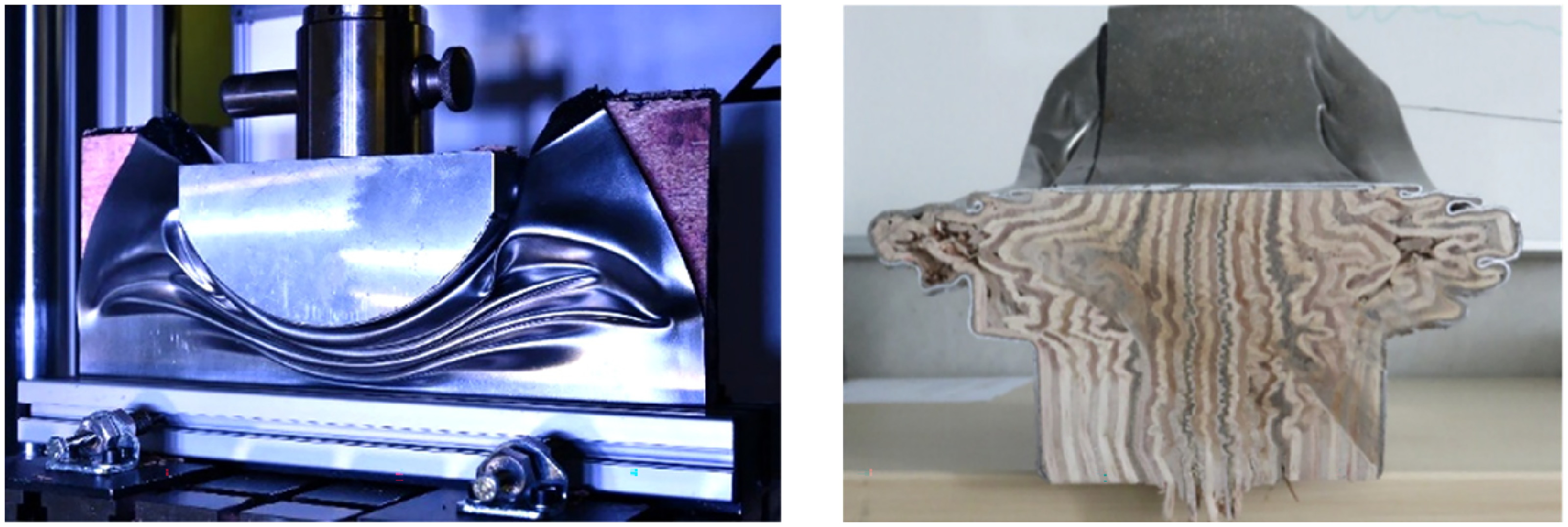
Test setup of pole crush test of hybridized specimen in testing machine (left). Sliced cross section of the post-test 100 mm specimen (right).
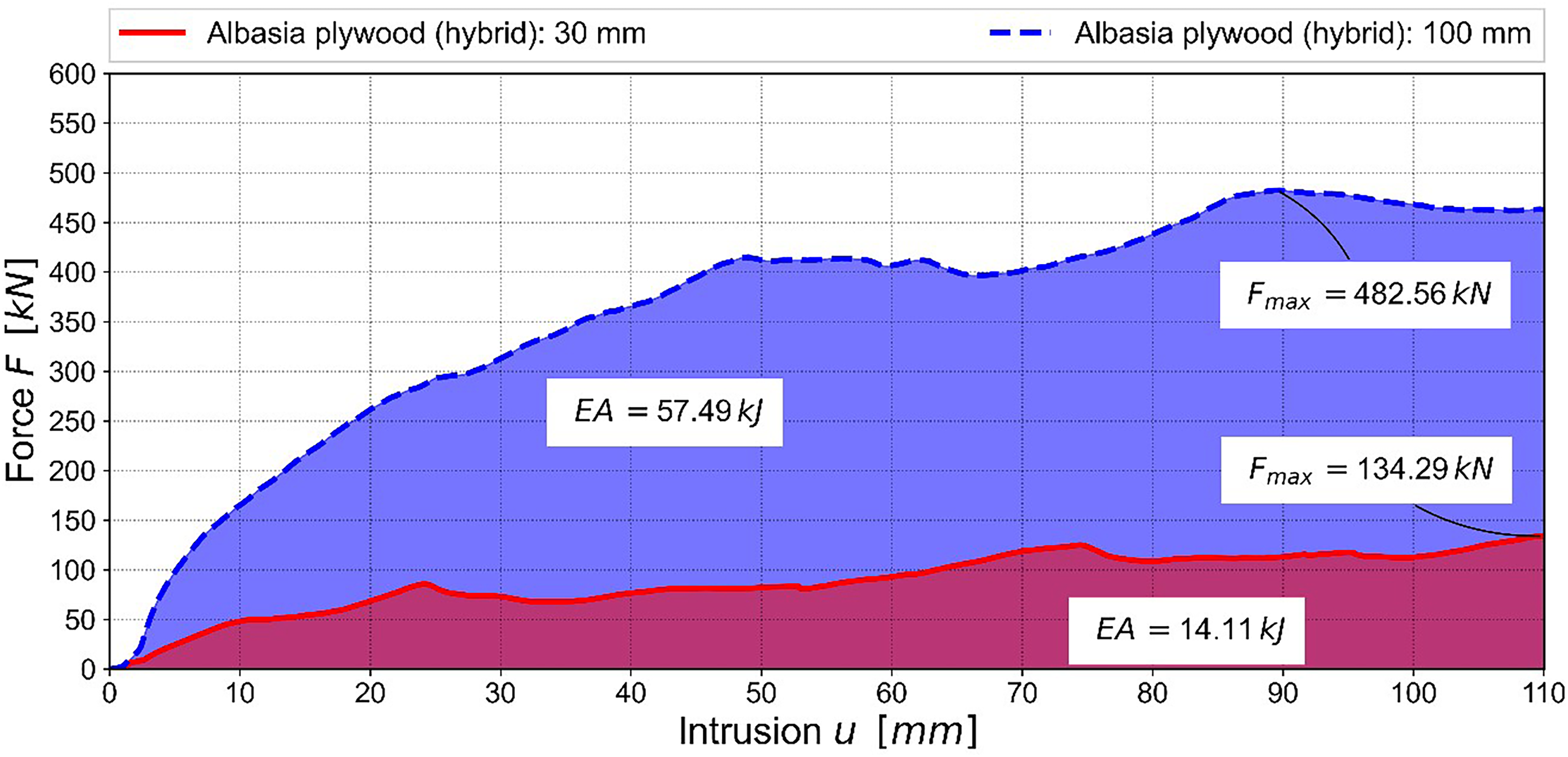
Force-displacement curves for tested 30 mm and 100 mm hybrid specimens. The absorbed Energy (AE) is indicated as the colored area under the curves.
In Figure 13 the energy absorption of the two different variants tested is calculated and shown as the colored areas under the load-displacement curves. One interesting aspect is the increase of the absorbed energy compared to the increased thickness of the plywood. For the specimen with a 30 mm plywood core the absorbed energy is 14.11 kJ whereas for the specimen with a 100 mm plywood core the absorbed energy is 57.49 kJ. The increase of the plywood thickness by a factor of 3.3 results in an increase of the absorbed energy by a factor of 4.1. A very similar effect could be observed for the tests without hybridization. This shows that the compaction is increased with the thickness of the specimen.
Influence of geometry
Experimental set up
In a next step the geometry was adapted to the side sill reinforcement currently used in series production. Therefore, the cross section was adapted to fulfill the design space requirements. Due to the restrictions in the test machine, the reference structure which has an original length of approx. 1.6 m in the vehicle structure was shorten to a total length of 800 mm. The plywood specimens were manufactured with the same total length. Due to the localized damage process during pole crushing, it is assumed that the reduced length has no influence on the crushing performance. Figure 14 shows the different profiles tested. On the left side the extruded aluminum profile currently used in series production is shown. Next to this a very simple rectangular geometry is shown which is mainly used to compare the tests to previous results and to analyze the maximum load level possible and the influence of the geometry. The two variants on the right show optimized geometries which fit into the design space available. The third profile from the left has an acute angle leading to the lowest weight of the three variants whereas the last variant has an obtuse angle representing a more conservative approach. The Albasia plywood has 39 layers and was hybridized in accordance with the previous tests with DC04 with a thickness of 0.65 mm. The sheet metal was bent and glued to the Albasia in a manual process using a 2-component epoxy adhesive. The tests were carried out with a ZwickRoell Universal Testing Machine with a quasi-static loading rate of 1 mm/s. The timber hybrid profiles as well as the reference structure were supported from both sides and a steel profile was used to close the gap between the base plate of the testing machine and the profiles (Figure 15). The goal of these tests was to adapt the hybrid material to the design space available and to analyze the material behavior in a direct comparison to the current state of the art. Therefore, the overall load displacement curve and the specific energy absorption were analyzed.
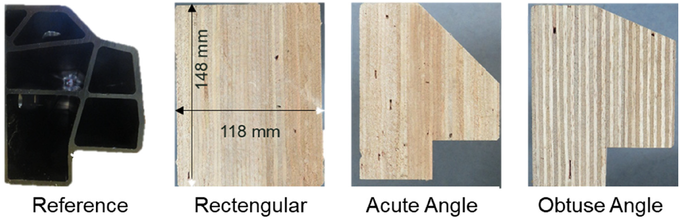
Overview of the cross-section of the reference side-sill and the three Albasia profiles tested.
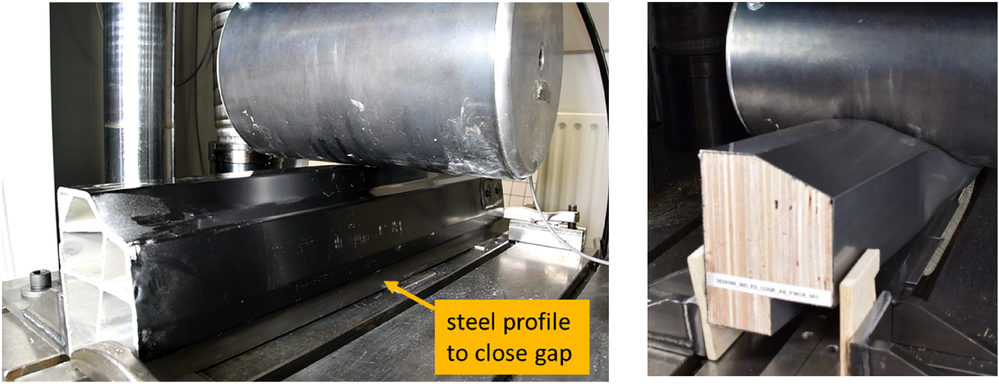
Specimen “Reference” before test (left), timber-steel-hybrid “obtuse angle” after test (right).
Results and discussion
In Figure 16 the results of the tests are shown. At a load level of 550 kN the maximum force of the testing machine has been reached. The specimens are almost completely compressed at this point. Table 1 shows that the energy absorption could be increased significantly for the rectangular and obtuse angle variants whereas the acute angle variant shows a reduced energy absorption compared to the aluminum profile. This effect is even more obvious if the energy absorption is divided by the weight of 1 m of the profile as shown in Figure 17. However, due to the significantly lower weight of the acute angle variant, the absorbed energy per kg\m is comparable to the aluminum reference structure.
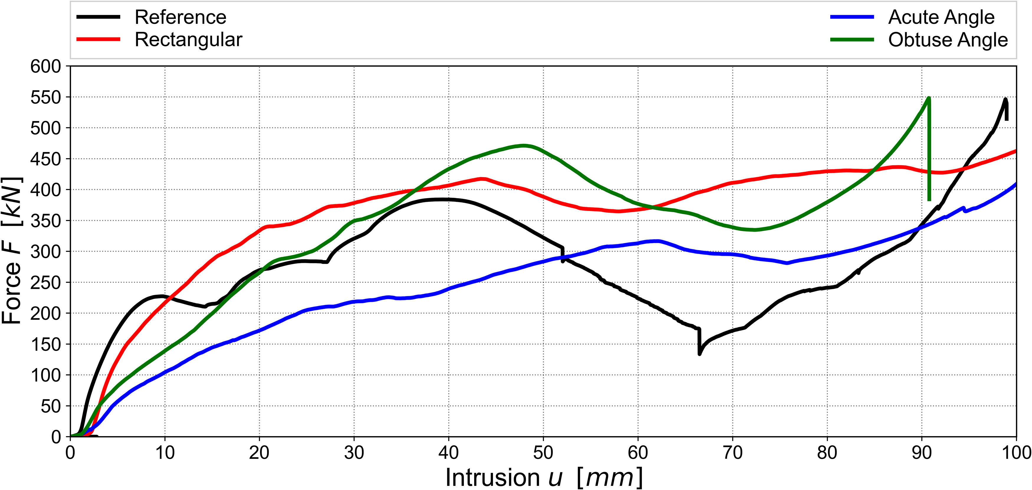
Force-displacement curves for the side sill reference structures compared to the three Albasia-steel hybrid variants.
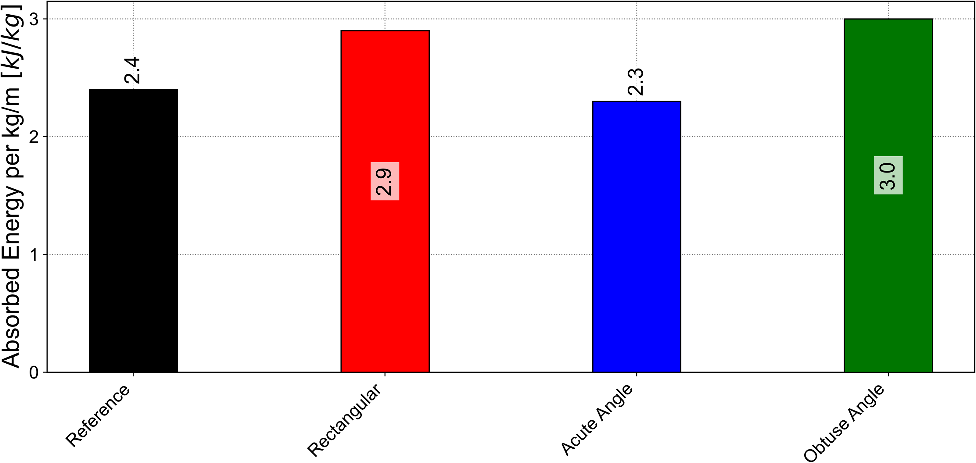
Absorbed energy per kg/m of the side sill reference compared to the Albasi-steel hybrid variants tested.
The test results illustrate the high potential of the hybrid materials. Compared to the reference structure, it is shown that more energy could be absorbed by the timber-hybrid profiles combined with a reduction of the structural weight. For the variant “Obtuse Angle” the specific energy absorption could be increased by 25% compared to the “Reference”. What could be a problem is the lower stiffness of the wood steel hybrid material at the first 15 mm of the test (Figure 16). Therefore, further optimization is necessary to fully match the load displacement curve of the aluminum profile currently used in series production.
Conclusion and outlook
The compression tests of Albasia wood and LVL expand the state of the art and underline the high potential of Albasia for compressive load cases. As the state of the art for material properties of Albasia wood is very limited these results make an important contribution for the usage of Albasia wood in technical applications. Furthermore, the results are presented as a function of density. This is of great importance especially for wood species with a low density like Albaisa. The tests of solid wood show a very good ratio of density and strength. It could be shown that these results could be transferred to plywood as different layups of LVL were tested. The test results will be especially important for simulations. A comparison of different plywood thicknesses and wood species underline the suitability of Albasia for the application. The tests also showed that the ratio between plywood thickness and energy absorption is not linear. In first promising results it could be shown that the hybridization of timber and steel is advantageous for energy absorption. Due to the plastic deformation of the steel sheets, the timber core material is prevented from breaking and instead is heavily compacted which results in high energy absorption. In a next step the geometry was adapted to an aluminum profile currently used in series production. In quasi static tests it could be shown that the specific energy absorption could be increased by approx. 25%. The results show that the current aluminum profile used could possibly be substituted with the timber steel hybrid material. This is a big achievement as the aluminum profile is a highly optimized part especially designed for this application. The hybridized profile is manufactured out of plywood and sheet metal. The geometries and also the manufacturing methods are comparatively simple. This approach already addresses mass production nevertheless further and more detailed analysis are necessary e.g., of the applying and curing process of the adhesive or the cutting of the plywood. The next steps in the project will be the implementation of the results into simulation models. To optimize the force-displacement curve the number of layers in the plywood with a grain direction parallel to the intrusion direction could be increased. Furthermore steal grades with a higher strength could be used. Finally tests with a high testing speed will be performed to analyze the influence of the strain rate.
Footnotes
Acknowledgment
We would like to thank the German Federal Ministry for Economic Affairs and Climate Action for the funding of the project “SuMatHrA”. We want to thank the “Projektträger Jülich” as executing agency for research funding and all project partners in the project “SuMatHrA”. We finally want to thank Maximilian Christians who supported the project with his Master thesis on the topic of material characterization.
Data availability statement
The datasets generated and analyzed during the current study are available from the corresponding author on reasonable request.
Declaration of conflicting interests
The authors declared no potential conflicts of interest with respect to the research, authorship, and/or publication of this article.
Funding
The authors disclosed receipt of the following financial support for the research, authorship and publication of this article: This work was funded by the German Federal Ministry for Economic Affairs and Climate Action [grant number 03LB2033].