
Abstract
This article focuses on finding a practical solution for improving the mechanical behaviour especially in bending in case of the composite materials reinforced with flax fabric. For this purpose, two kinds of composites having the same number of layers are mechanically tested: the flax/epoxy composite and the flax/glass/epoxy composite (hybrid composite). The mechanical tests used were tensile test and bending test (three-point method). Different results corresponding to the weft or warp directions were remarked in case of the hybrid composite: for example, the maximum values of the tensile strength and the flexural strength measured in the weft direction are 40.63% and 34.61% greater, respectively, than the values corresponding to the warp direction. This article reports the improvement of the mechanical properties by replacing the flax reinforcement with glass reinforcement in the two upper and lower layers of the flax composite materials: increasing with 35.19% in terms of Young’s modulus E recorded in the tensile test, with 79.86% of the maximum value of the tensile stress and with 91.08% of the maximum value of the flexural stress. Composite beam theory was considered and theoretical approaches were validated by the experimental results.
Introduction
Statistics over the last decade shows an increasing interest for manufacturing of the plastic composites reinforced with natural fibres: flax,1,2 hemp,2–4 jute2,5 and wood fibres. 6 Statistics shows 4,275,049 ha 1 of harvested area of flax fibres during 2001–2011. France and Belarus each held 26% of the total harvested area of flax fibres in 2011 1 while Russian Federation and China held 20% and 14% of the total harvested area, respectively.
The applications of the composite materials reinforced with flax fibres include1,2 automotive interior components (such as door and panels of interior design), roof panels, insulation wall panels, boat hulls, 1 tennis rackets, surfboards, 1 packaging boxes, chairs 1 and other furniture parts, and wind turbine blade. 7
The major advantages of such natural fibres consist in the following: these represent a renewable source 5 and provide lower weight to the new composites due to their lower densities compared to the classical reinforcement fibres (glass, carbon, boron and Kevlar fibres) as shown in Table 1. The flax fibres are recommended for insulation panels since the sound absorption coefficient recorded in case of the flax/Araldide composite is 21.42% 8 greater than the corresponding value recorded in case of the E-glass/Araldide composite.
Comparison between the natural fibres and other fibres in terms of density.

But natural fibres have some major disadvantages: these absorb water3,6,12,13 in wet environments and degrade in such environments and under the action of ultraviolet (UV) light;
13
smoke emission is high when firing.1,6 The water absorbed (13.5% weight) by the flax/epoxy composite until saturation was 12.85 times greater than the water absorbed (1.05%) by the glass/epoxy composite.
12
In the case of the flax fabric/epoxy composites, the accelerated UV weathering tests for 1500 h by ageing cycles (exposing to Fluorescent UV light at
Many applications of the composite materials reinforced with flax fibres refer to randomly reinforcing with chopped flax fibres, 1 to reinforcing with continuous flax fibres by using biaxial woven fabric 7 or to reinforcing with continuous unidirectional fibres.12–14
Comparative analysis was made 14 regarding the results obtained in case of composite materials based on epoxy resin reinforced with natural fibres (flax, jute, sisal, hemp). The tensile modulus corresponding to the flax/epoxy composite was reported to be 152.49%, 102.35% and 182.35% 14 greater than that corresponding to the composite materials reinforced with jute, sisal and hemp fibres, respectively.
Recent articles15,16 revealed some ways to improve the mechanical properties of the composite materials reinforced with flax fibres. For example, Xue and Hu 15 showed that NaOH treatment applied to the flax reinforcement leads to the improved mechanical properties of such composite materials. Another work 16 also showed that the interfacial bonding between fibres and polymeric matrix can be improved by chemical treatments (with maleic anhydride, vinyl-trimethoxy silane, maleic anhydride-polypropylene copolymer) applied to the matrix.
A recent paper 7 has tried to replace E-glass fibres with flax fibres in structural composites. For this purpose, the authors had investigated two variants of the 3.5-m composite rotor blades: one made of flax/polyester and the other one manufactured from E-glass/polyester. It could be remarked that the flax/polyester blade is 10% lighter than the E-glass/polyester blade; both the versions satisfy the design and structural integrity requirements for an 11-kW turbine according to the certification standards. But the E-glass/polyester blade was stiffer because the maximum deflection recorded in case of the flax/polyester blade was greater than in case of the E-glass/polyester blade.
Some experimental investigations (tensile and compression tests) were conducted on flax/epoxy and glass/epoxy composites 17 made of the same epoxy matrix system SR 8200/SD 8205 and containing the same 43% fibre volume ratio. It was shown that the ultimate tensile stress, tensile modulus E and ultimate compression stress corresponding to the glass/epoxy composite were 123.53%, 50.03%, 76% greater, respectively, than the ones measured for the flax/epoxy composite.
The literature does not report results on hybrid laminated composites reinforced with both flax and glass woven fabrics made of continuous flax/glass fibres. This is the reason why the present work proposes a hybrid solution of the composite material reinforced with both flax and glass fabric. The novel hybrid composite should combine the advantages of both the flax fibres and the glass fibres. The advantages of the flax fibres have already been mentioned above. The advantages of glass fibres are good ratio between strength and weight, low cost, these are not hydrophilic; these are alkaline resistant. Glass fibres have the tensile strength of 3515 MPa 9 greater than the value of 700 MPa recorded in the case of flax fibres. 1
In order to determine which is the better solution, the mechanical properties of the hybrid composite material are compared with the ones corresponding to the composite material reinforced only with flax fibres.
On the other hand, a theoretical model of the beam theory is approached for both the composite materials involved in this study: flax/epoxy composite and glass/flax/epoxy composite. First of all, the beam theory used in the case of laminated composite materials is presented taking into account the literature18–20 in order to compute both the equivalent modulus of elasticity
Finally, the theoretical results obtained by using the beam theory of the laminated composite are compared with the experimental results obtained in bending tests.
Materials and work method
Structure of the composite materials tested
In this investigation, two kinds of composite materials are tested. The first composite material contains eight layers made of Epolam 2015 epoxy resin reinforced only with flax woven fabric. The other composite material is a hybrid one because some layers are made of Epolam 2015 epoxy resin reinforced with flax woven fabric, while the others are reinforced with glass woven fabric. The content of the fibres was equal to 40 wt%. Figure 1 shows the layout of the layers of the hybrid composite material.
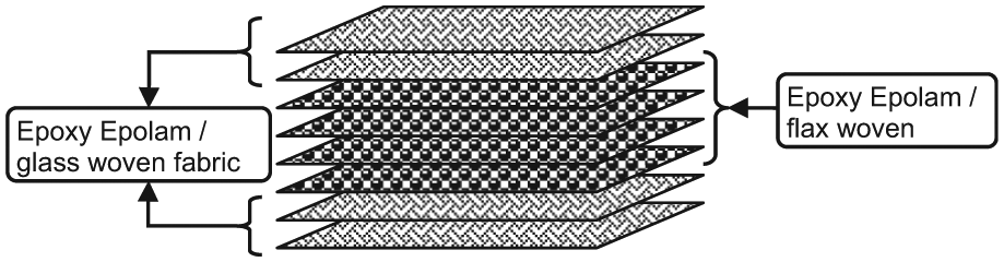
Laminated structure of the glass/flax hybrid composite material.
The densities of the woven fabrics used are
First, a board (600 × 350 mm2) made of each composite material was manufactured by using hand lay-up technology. The thickness of the flax/epoxy composite board was equal to
Then, the plates made were cut to obtain specimens for tensile test according to SR EN ISO 527-4:2000; 21 the dimensions of the rectangular specimens for bending were 15 × 100 mm2 according to SR EN ISO 14125:2000. 22
In the case of each composite material tested, two sets of specimens were manufactured for each mechanical test: a set of specimens whose length is parallel to the weft direction of the flax fabric, while the other set contains specimens whose length is parallel to the warp direction. This consideration was made by taking into account that the flax yarns used for weft and warp directions are different according to the technical sheet of the flax woven fabric.
Mechanical testing
The testing equipment LR5K Plus machine manufactured by LLOYD Instruments used for both tensile test and flexural test, consists of hydraulic power supply. The maximum force capacity is ±15 kN. The speed of loading was equal to 1 or 1.5 mm/min during the tensile test or during the bending, respectively. The three-point method was used for testing in bending (flexural test).
Before each mechanical test of a specimen, the dimensions of the cross section were accurately measured, and then, they were considered as input data in the software program of the machine.
The testing equipment allowed us to record pairs of values in the form of text files having 200–300 lines: tensile force F and extension of the specimen; bending force F and deflection v at the midpoint of the flexural specimen. The experimental data were statistically processed in order to determine the mechanical properties. The modulus of elasticity E in the both tensile test and bending test was determined on the linear portion of the loading curve. Therefore, the average values of the following quantities could be accurately computed for tensile test: Young’s modulus E in tensile test; maximum tensile stress
The average values determined in the bending test are as follows: Young’s modulus E in flexural test; flexural rigidity
Theoretical approaches
Beam theory
All layers of the composite materials analysed are reinforced with bidirectional woven fabric made of flax or glass fibres. Moreover, the layers made of the same material and with the same thickness are symmetrically placed with respect to the median surface of the composite material. It follows that both composite materials tested are symmetric special orthotropic laminated composite materials.
The general constitutive equation18,19 of the plate element made of laminated composite material is:

where
In the case of a plate element made of symmetric special orthotropic laminated composite (Figure 2), subjected just to the bending, the constitutive equation (1) is reduced to:
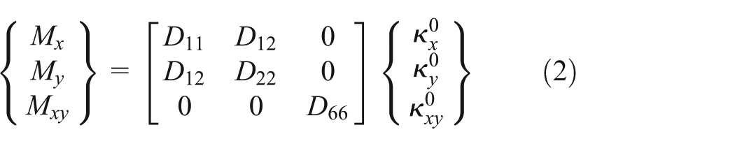
because

Internal forces developed at the level of the median surface of a plate element made of laminated composite material.
In relation (2), the curvatures are computed by using the following relations:

where
In relation (2), the terms of the bending rigidity matrix

where
Since the orientations of the fabrics are the same

where

Relation (2) may be written in the following form:
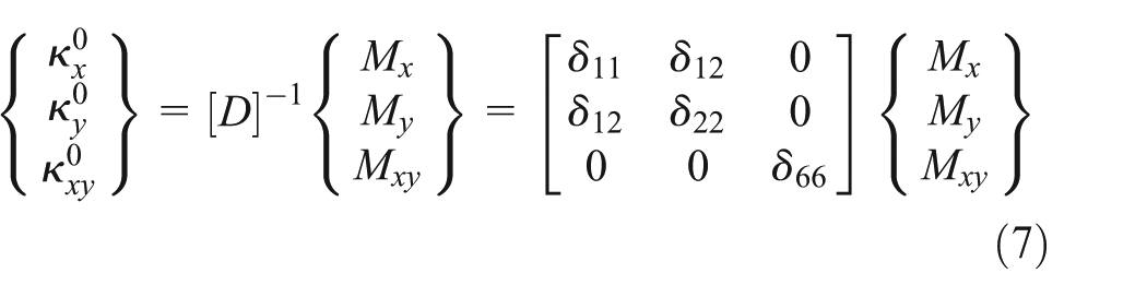
where
The relations between the vector of moments

lead to the following relation:18,19

where
In the case of beam theory,
19
it is assumed that the bending moment


Composite beam subjected to bending by the three-point method.
Thus, using the first relation from equation (3), relation (7) leads to:
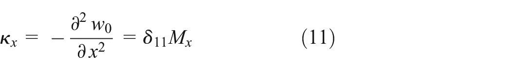
and relation (9) is reduced to:

Relation (11) is usually written as follows by using relation (12):

where
Considering the beam shown in Figure 3 that is subjected to the three-point bending, the differential equation (13) of the deformed median fibre of the beam may be written in the following form:

where
The boundary conditions of the beam (Figure 3) are:
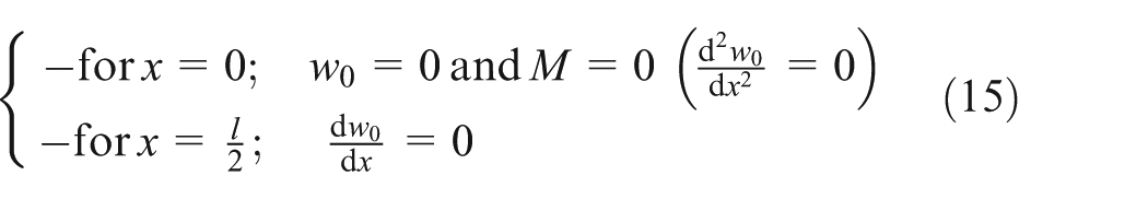
where the condition written for
By integrating relation (14) and considering the above boundary condition (15), the vertical deflection

The maximum deflection

where
Particular cases
Herein, the components of the rigidity matrix in bending
For this purpose, both the laminated composite structures are represented in Figure 4. The thickness and the coordinates
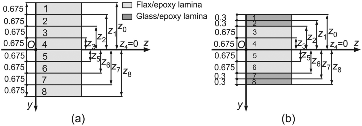
Thickness and coordinates of the layers in the case of two laminated composites analysed: (a) the flax/epoxy composite and (b) the glass/flax/epoxy hybrid composite.
The components of the rigidity matrix in bending


where
Relations (18) are replaced into relation (12) in order to obtain the theoretical formula of the modulus of elasticity

where
In the same manner, the components of the rigidity matrix in bending


where
Relations (20) are substituted into relation (12) in order to obtain the theoretical formula of the modulus of elasticity
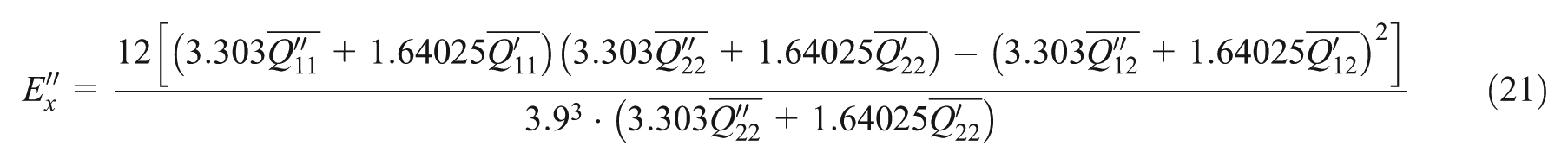
where
Finally, the theoretical values calculated by using relations (19) and (21) were compared with the experimental results in order to validate the theoretical models of the beam corresponding to both the composite materials involved in this work.
Results and comparisons: discussions
Experimental results
Figure 5 shows the stress–strain
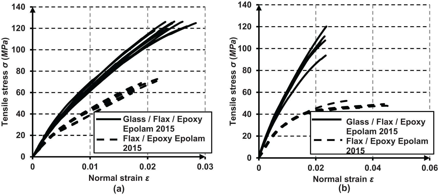
Stress–strain
In both the cases of tensile loading, it may be remarked that the stress–strain curves corresponding to the flax/epoxy composite material are located below the ones recorded in case of the hybrid composite material (glass/flax/epoxy composite). This means that the stiffness of the hybrid composite material is greater than the stiffness corresponding to the composite material reinforced only with flax woven fabric.
Figure 6 comparatively shows difference concerning the mechanical behaviour in the tensile test in case of the two composite materials analysed in terms of tensile strength (Figure 6(a)) and Young’s modulus E (Figure 6(b)).

Comparison of the tensile properties in case of the tested composite materials: (a) tensile strength and (b) Young’s modulus in tensile.
Regarding the flax/epoxy composite material, it may be observed that the maximum value of the tensile stress
In the same manner, the results obtained in the case of the hybrid composite (glass/flax/epoxy) lead to the following remarks: the maximum value of the tensile stress
It could also be observed that the tensile properties measured in the weft direction increase in the case of hybrid composite with respect to the ones corresponding to the flax/epoxy composite as follows: with 35.19% in case of Young’s modulus E and with 79.86% for the maximum value of the tensile stress
The other tensile properties of the composite materials tested are shown in Table 2.
The average values of the mechanical characteristics measured in the tensile test.

Figure 7 shows the force–deflection (F–v) curves recorded during bending tests in case of both composite materials tested. It may be remarked again that the force–deflection curves (F–v) corresponding to the flexural specimens whose length is parallel to the weft direction are located above the ones that are parallel to the warp direction. This remark leads to the conclusion that the specimens cut parallel to the weft direction are stiffer than the ones cut parallel to the warp direction.

Force–deflection
Figure 8 shows the comparative mechanical properties determined in the bending test in terms of the maximum bending stress

Comparison of the properties determined in the bending test in case of the tested composite materials: (a) maximum bending stress and (b) Young’s modulus in bending.
Regarding the flax/epoxy composite material, an increase was recorded for the mechanical properties corresponding to the weft direction with respect to the ones recorded in the warp direction: with 12.69% in the case of the maximum bending stress
In the case of the hybrid composite material, the average value of the maximum bending stress
In case of the hybrid composite, it could also be observed that the flexural properties measured in the weft direction increase with respect to the ones corresponding to the flax/epoxy composite as follows: with 91.08% for the maximum value of the flexural stress
The average values of the mechanical characteristics measured in the flexural test.

Theoretical results
To compute all terms of the matrix of rigidity
The required components of the rigidity matrix

By substituting relation (22) into relation (19), the theoretical modulus of elasticity corresponding to the flax/epoxy laminated beam with respect to the weft direction of the flax fabric was computed:

To compute the modulus of elasticity
For this purpose, the results obtained in the case of bending of the specimens made of glass/epoxy composite from a previous work
24
are used:
The required components of the rigidity matrix

Substituting relations (22) and (24) into relation (21), the theoretical modulus of elasticity corresponding to the glass/flax/epoxy laminated beam with respect to the weft direction of the flax fabric was computed:

Theoretical versus experimental results
All experimental and theoretical values regarding the equivalent modulus of elasticity
Comparison of the theoretical and experimental results regarding the modulus of elasticity

In order to compare the results obtained by using the theoretical model of the composite beam with the ones experimentally obtained, the last column of Table 4 shows the values of the error computed by using the formula:

Conclusion
This article proposes a way to improve the mechanical behaviour of the composite materials reinforced with flax fabrics by reinforcing with glass fabric of two extreme layers (top and bottom layers). The improvements are significant regarding the tensile behaviour, but the increase in the mechanical properties determined in the bending test is truly spectacular. In the case of the hybrid composite, the modulus of elasticity E in bending is more than double (136.17%) and almost triple (182.56%) in the weft/warp direction, in comparison with the corresponding values recorded in the same directions of the flax/epoxy composite material. The maximum value of the flexural stress recorded in the weft direction is almost double (91.08%) in the case of the hybrid composite.
The theoretical values of the equivalent modulus of elasticity
The relations (19) and (21) corresponding to equivalent moduli of elasticity of the bending beam models presented in this work, may be used in the case of any beam subjected to bending, made of such laminated composite materials.
Herein, the importance of replacing the reinforcement material with glass fabric in the extreme layers, is shown because the equivalent modulus of elasticity
Footnotes
Acknowledgements
The author hereby acknowledge Transilvania University of Brasov for providing the infrastructure used in this work.
Declaration of conflicting interests
The author declares that there is no conflict of interests regarding the publication of this article.
Funding
This research received no specific grant from any funding agency in the public, commercial or not-for-profit sectors.