
Abstract
A promising approach for the development of sustainable and resource-saving alternatives to conventional material solutions in vehicle structures is the use of renewable raw materials. One group of materials that has particular potential for this application is wood. The specific material properties of wood in the longitudinal fiber direction are comparable to typical construction materials such as steel or aluminum. Due to its comparatively low density, there is a very high lightweight construction potential especially for bending load cases. Structural components of the vehicle body are exposed to very high mechanical loads in the case of crash impact. Depending on the component under consideration, energy has to be absorbed and the structural integrity of the body has to be ensured in order to protect the occupants. The use of natural materials such as wood poses particular challenges for such applications. The material characteristics of wood are dispersed, and depend on environmental factors such as humidity. The aim of the following considerations was to develop a material system to ensure the functional reliability of the component. The test boundary conditions for validation also play a key role in this context. The potential of wood–steel hybrid design based on laminated veneer lumber and steel was investigated for use in a component subjected to crash loads such as the door impact beam. The chosen solution involves a separation of functions. A laminated veneer lumber-based beam was hybridized with a steel strip on the tension side. The steel strip was designed to compensate the comparatively low elongation at fracture of the wood and to ensure the integrity of the beam. The wooden component was designed for high energy absorption due to delamination and controlled failure during the impact, while maintaining the surface moment of inertia, i.e. the bending stiffness of the entire component. This approach was chosen to ensure the functional safety of the component, avoid sudden component failure and utilize the high potential of both materials. The tests carried out provided initial functional proof of the chosen solution. The hybridization achieved significantly higher deformations without sudden failure of the beam. In addition, bending capabilities were increased significantly compared to a beam without hybridization. In comparison with a state-of-the-art steel beam, the hybrid beam was not able to achieve the maximum deformation and the target weight of the hybrid beam. Further optimization of the hybrid beam is therefore necessary.
Keywords
Introduction
The use of wood in vehicle structures has become more attractive in recent years, due to the increasing demands to reduce CO2 emissions. 1 However, the use of new material solutions, and in particular natural materials such as wood, involves multiple challenges. This applies in particular to crash-relevant components that ensure the safety of vehicle occupants. For this reason, suitable material and component concepts have to be developed that ensure functionality despite scattered characteristics and the dependence of the material properties on ambient conditions such as humidity. 2 In addition to extensive simulations, physical tests are required at an early stage of the development process that realistically replicate the later installation position of the component. 3
The potentials and problems of wood in vehicle structures are shown below using a generic door impact beam manufactured in a hybrid veneer-based architecture concept. In addition to the development of the wood-hybrid material, the selected test method for validation of the components was considered. The door impact beam was identified as a reference component since it can be manufactured and tested separately from the vehicle structure. The door impact beam is welded into the door in the bodyshell and is manufactured using state-of-the-art technology from high-strength yet ductile materials. Press-hardened steels are a well-suited option here, for example. Depending on the vehicle manufacturer and model, it is an almost straight beam. For this reason, there are numerous projects in which new material solutions have been validated using the door impact beam. 4 The use of wood has also been considered in several projects in this context. In particular, the projects Wood C.A.R., 5 HAMMER, 6 and For(s)tschritt are worthy of mention: the results presented in this paper are derived from the project For(s)tschritt funded by the German Federal Ministry of Economic Affairs and Energy (BMWi).
In general, wood is very suitable for bending loads. Due to its very low density compared to other construction materials, components with the same weight can be designed thicker and the bending stiffness could be increased. 7 Unlike quasi-static load cases, common in the construction sector, crash load cases have to be considered in the dimensioning of a door impact beam. This is where wood has a disadvantage. Compared to metallic materials, wood has a very low tensile elongation at fracture. For the beech wood considered here, this is about 0.8% in the longitudinal fiber direction. 8 However, catastrophic failure is not permitted in a vital component such as the door impact beam. For this reason, suitable materials have to be selected for hybridization in order to achieve sufficient deformation of the beam without sudden failure despite the low elongation at fracture. In the “Hammer” project, 9 this problem was addressed by using aramid fibers for hybridization. In the project under consideration here, steel was selected as the material for hybridization due to the fact that it allows simple recycling and maximum reduction of CO2 emissions.
In the following sections, the examined material structures, test methodology evaluating the wood-metal composite and achieved results based on the respective test setup are discussed in detail.
Material, geometry, and production
The reference component is a door impact beam made of press hardened steel with a length of 963 mm, a width of 96.6 mm and a double wave geometry (see Figure 2).
The wood-steel hybrid beams were produced with a length of 900 mm based on the selected reference component. The steel strip was cut to a length of 1000 mm at a width of 50 mm and glued to a trapezoidal wooden profile (for geometry see Figure 1). In this way it was possible to use the overhang of the steel strip on both sides of the beam to fix the wood hybrid beams to surrounding structures.
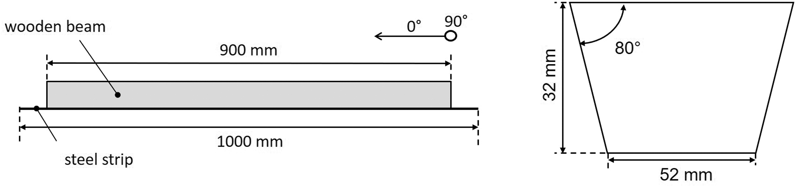
Side view of wooden beam with steel strip (left); front view of wooden beam without steel strip (right).
The beams were produced in a multi-stage process. First, boards were made of beech-veneer (laminated veneer lumber). The veneer layers were pressed to plates using a fiber-reinforced polyurethane adhesive system. The layer structure was varied by changing the orientation of individual layers, enabling a total of five different laminate structures to be produced (see Table 1). After the plates were manufactured, they were cut to the geometry shown in Figure 1 (right).
Laminate structures considered (B = beech-veneer).
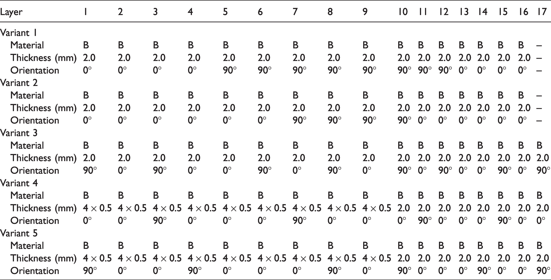
Only wooden beams were tested with Variants 1 and 2. Variant 3 considers both wooden and wood-steel-hybrid beams whereas in Variants 4 and 5, only wood–steel–hybrid beams were tested. The beams were hybridized with sheets of high-strength steel with a thickness of 1.2 mm using a two-component epoxy resin provided by the company Jowat SE. The adhesive was cured for one hour at a temperature of 70°C. The steel quality and thickness were chosen on the basis of a numerical optimization process. In order to optimize the bond between wood and steel strip, two different coating systems were considered for Variants 4 and 5. Coating system “A” was a polyester based coating usually used in architecture applications. Coating system “B” was also a polyester-based top coat used for domestic appliances. Figure 2 shows an example of a wood–hybrid beam and the reference component.
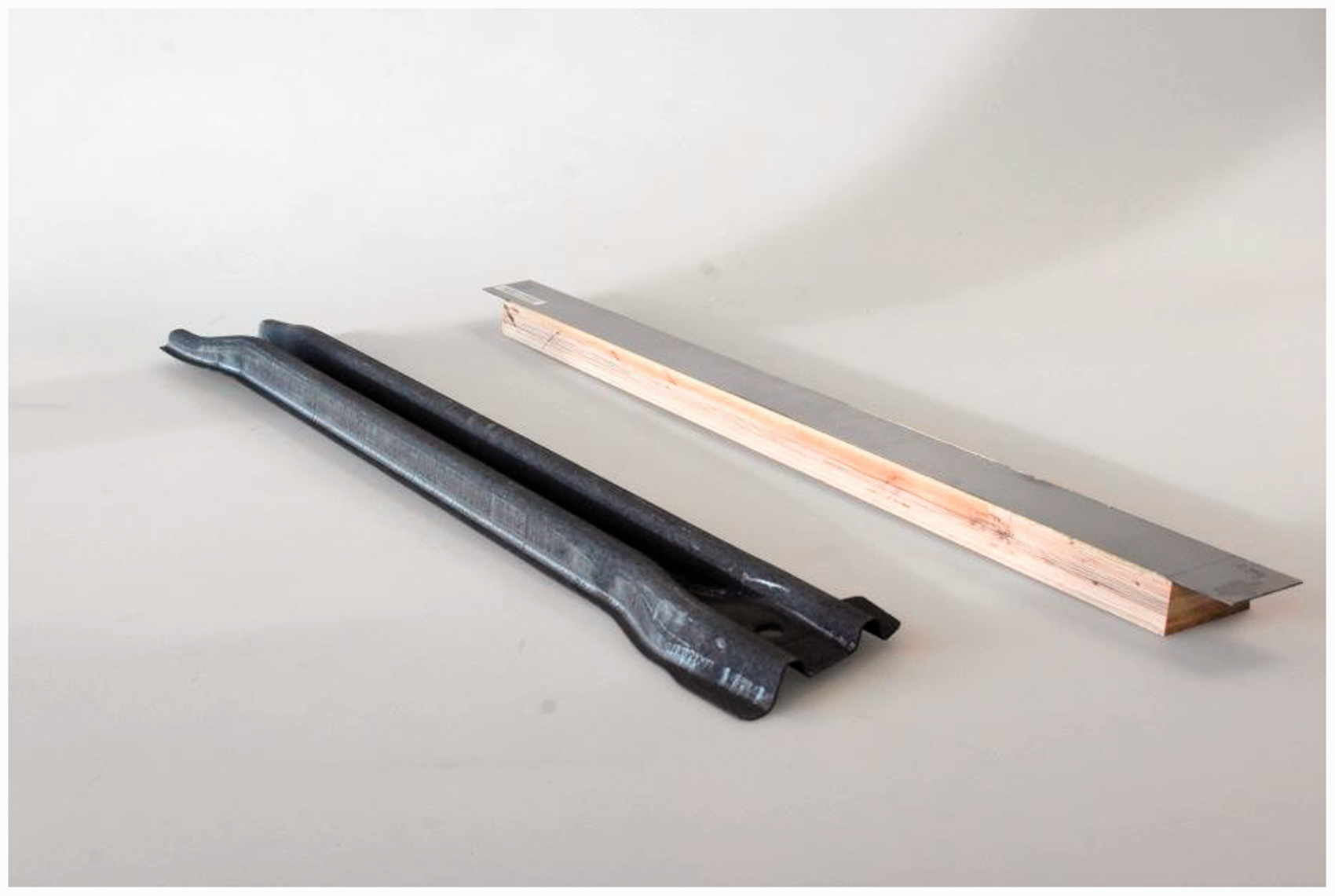
Reference steel component (left); generic wood–steel hybrid component (right).
The selected geometry serves as a generic structure and represents a simplification of a complex structure part developed as part of the project For(s)tschritt. Since production restrictions also have to be considered in this context, very thin veneer was selected for the outer covering layers for Variants 4 and 5.
Testing methodology
The objective of the generic wood-hybrid beam tests was to provide general functional proof for the wood-metal hybrid and to classify the results compared to the reference component. The reference load cases were the quasi-static pole door push-in test according to FMVSS 214S 10 and the dynamic pole collision according to FMVSS 214P 11 respectively European New Car Assessment Program (Euro NCAP). 12 These tests were simplified to a three-point bending flexural test. For the selected component, these load cases constitute the maximum mechanical stress levels. Two particularly relevant factors for the evaluation of the component were identified: first the strain rate dependence of the material properties, which can only be determined in the dynamic test, and second the influence of the retention forces which act in the peripheral area when the beam is fixed in the door. The selected test setups are described in more detail below.
Three-point bending flexural test (quasi-static)
The first stage involved quasi-static three-point bending flexural tests. The test setup shown in Figure 3 was selected for the preliminary tests in the three-point bending flexural test. The profiles were tested with and without a reinforcing steel strip on the tension side.
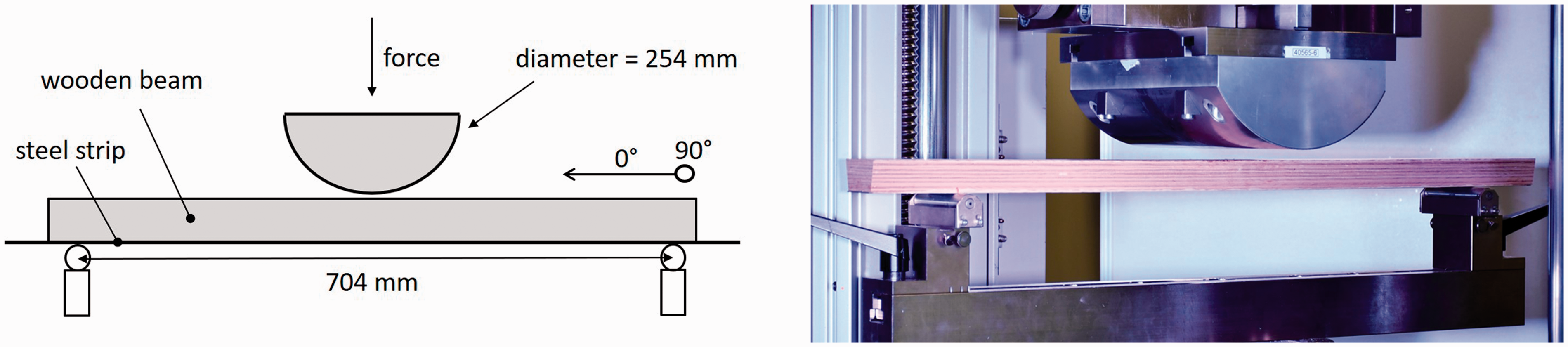
Test setup – three-point bending flexural test (quasi-static): schematic diagram (left), test bench (right).
Three-point bending flexural test (quasi-static with retention forces)
Special absorbers were developed in order to be able to map the retention forces. The “absorber units” work by means of a cutting edge that is pulled through an aluminum tube during the test, thereby building up retention forces (see Figure 4). Components can be connected via two linear guides. The retention forces were determined based on the overall vehicle simulation. The force levels can be varied by changing the wall thickness of the aluminum tube. The absorber units are fitted with force and distance measurement facilities. This enables optimum comparability between simulation and test, thereby accurately determining the energy absorbed.
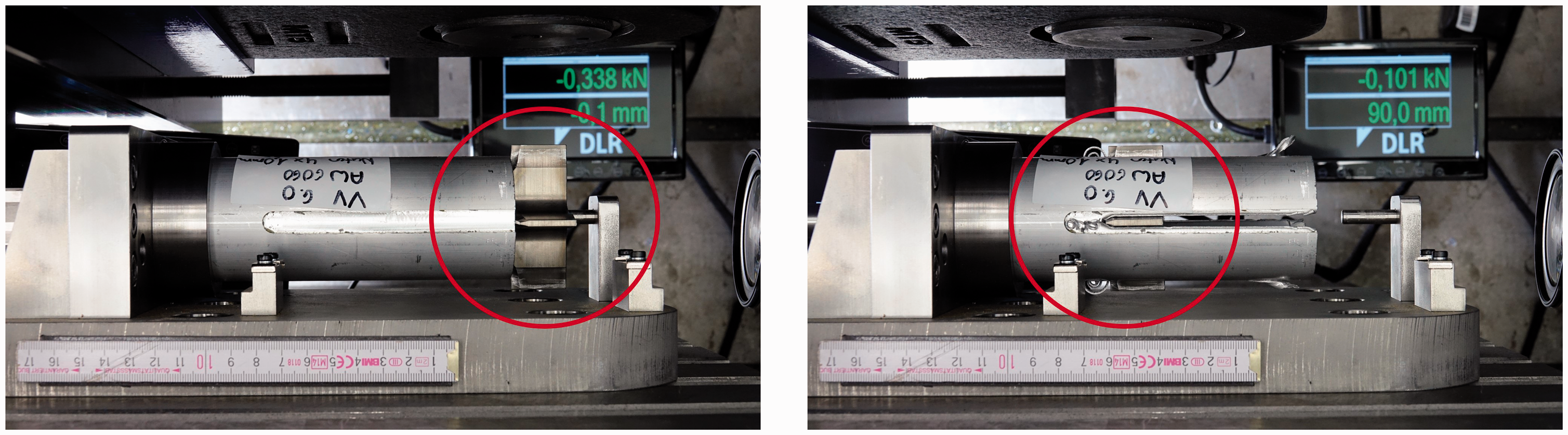
Quasi-static test with retention forces: absorber unit before test (left), after test (right).
Figure 5 shows the experimental setup with force boundary conditions in the quasi-static test. The two forces Fretention represent the retention forces in the absorber units and are reaction forces to the test force Ftest. In addition to the mechanical properties of the beam, the influence of the overlap in the peripheral area was also examined.
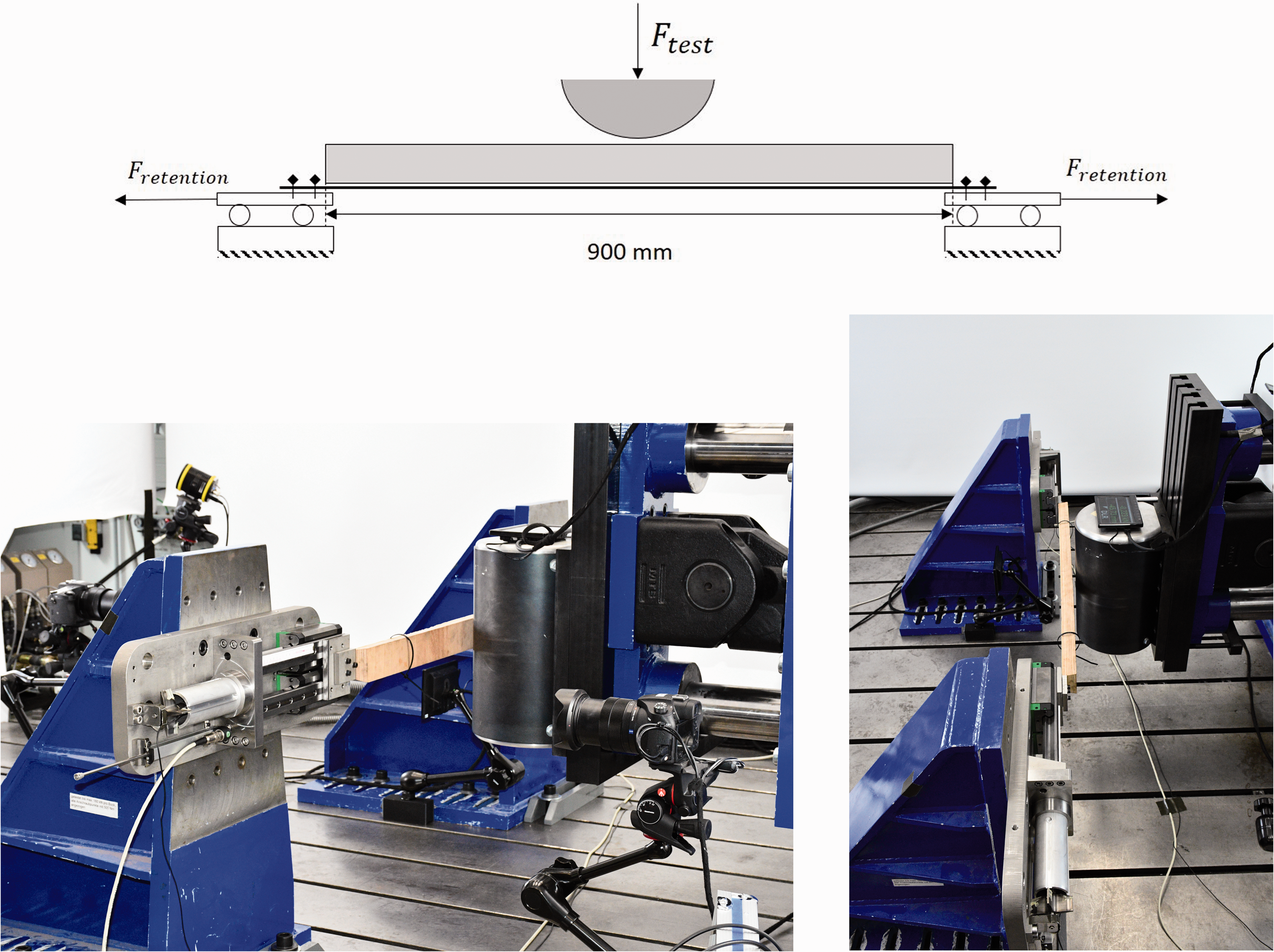
Quasi-static test with force boundary conditions: schematic diagram (top), test bench (bottom left/ right).
Three-point bending flexural test (dynamic with retention forces)
Finally, impact-dynamic tests were conducted to represent high strain rates. The drop tower test setup shown in Figure 6 was developed for this purpose. The impactor with a weight of 84.3 kg was released from a height of 1.5 m. This corresponds to an initial energy of about 1240 J and a theoretical velocity of around 5.4 m/s at impact. Due to friction losses in the vertical guides, the true impact theoretical velocity of the impactor is approximately 5 m/s. Since the drop height is constant for all tests, the results are directly comparable showing the influence of the variants.
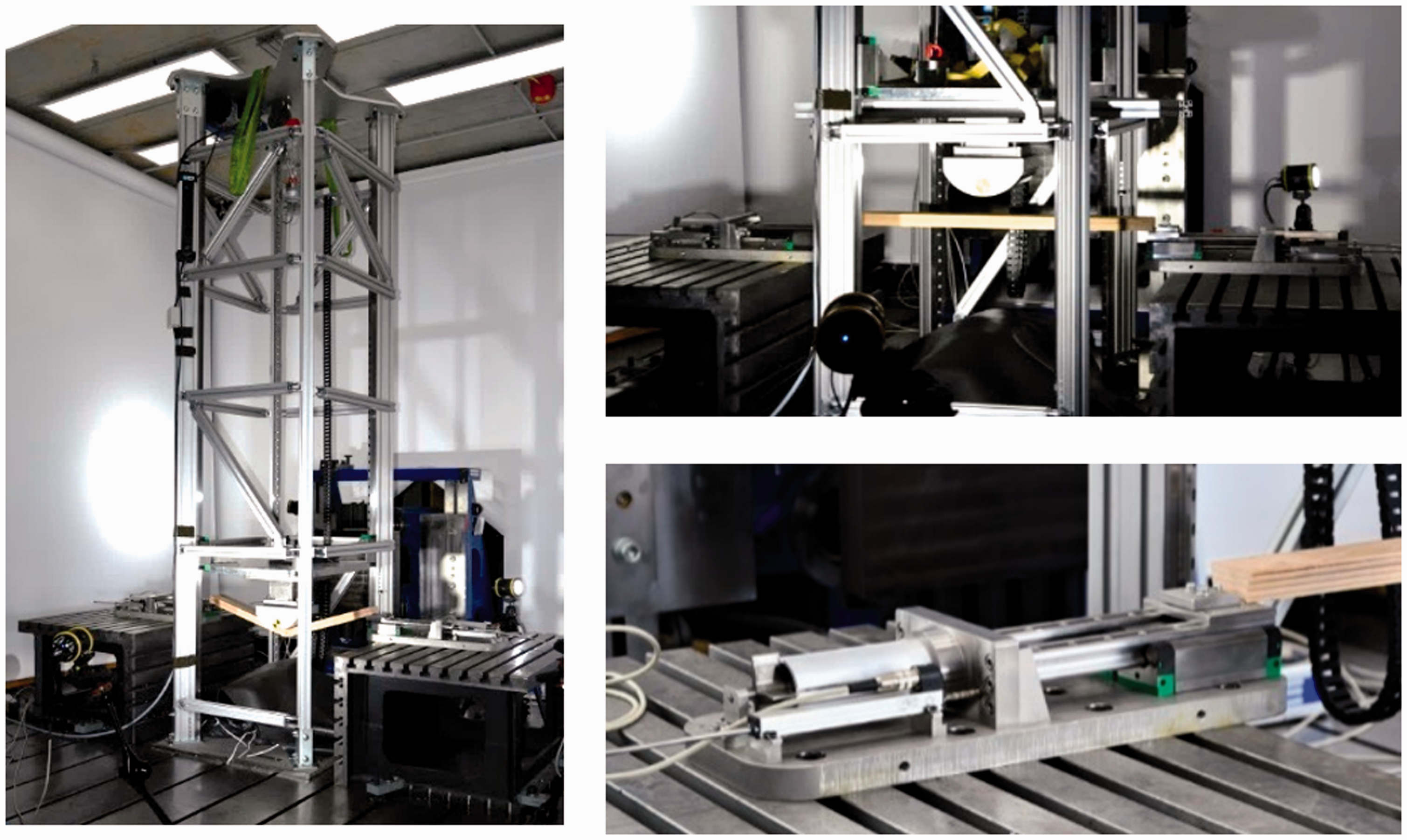
Test setup – impact-dynamic tests: drop tower (left), specimen with impactor (top right), specimen with absorber (bottom right).
Comparable to the quasi-static test setup, the steel–wood hybrid beam was connected to absorbers on both sides. The force level of the absorbers was chosen identical to the quasi-static tests, with measuring carried out in the same way.
Results and discussion
Results and discussion three-point bending flexural test (quasi-static)
Figure 7 shows the test results of wooden beams without steel strip (Variants 1–3) at quasi-static loading with a test speed of 300 mm/min.
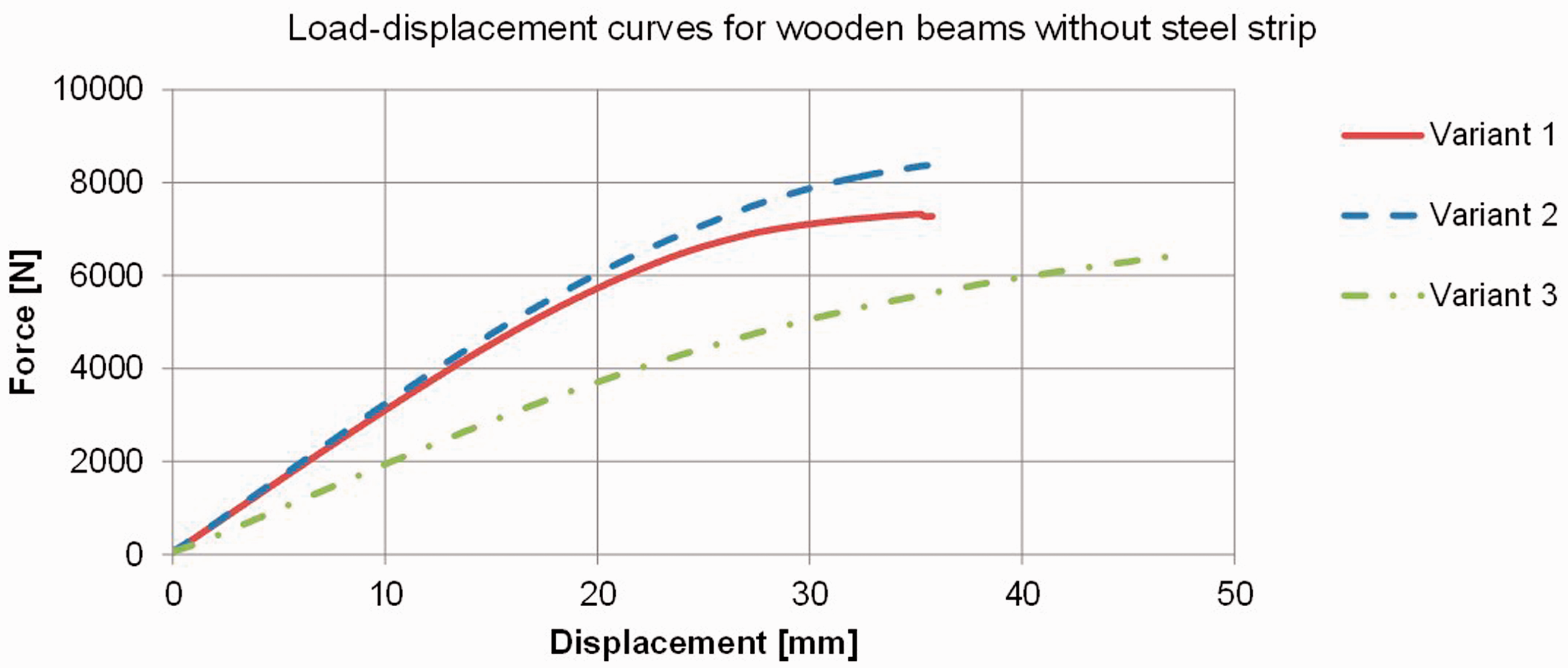
Testing of wooden beams in three-point bending test.
The test setup was chosen as explained in an earlier section. Due to a high proportion of 0° layers in the outer layers, the force levels of Variants 1 and 2 are higher compared to Variant 3. For Variants 1 and 2 a sudden failure occurs at a deformation of about 35 mm. With Variant 3, larger deformations can be achieved before the beam fails. The maximum deflection up to failure of the component is critical since early failure of the beam has to be prevented.
Furthermore, wood-steel hybrid components were tested, whereby the layer structure according to Variant 3 was selected. In the initial tests, the three-point bending flexural test resulted in a sudden “flake off” of the steel strip instead of the plastic deformation desired (see Figure 8). One reason for this was that the bonding was not able to transmit the shear forces generated in the interface between the wood and the steel strip. Failure of the lower wood layers resulted in peeling stresses, which additionally facilitated the detachment of the steel strip. Therefore, no reinforcement effect was achieved with the steel strip.
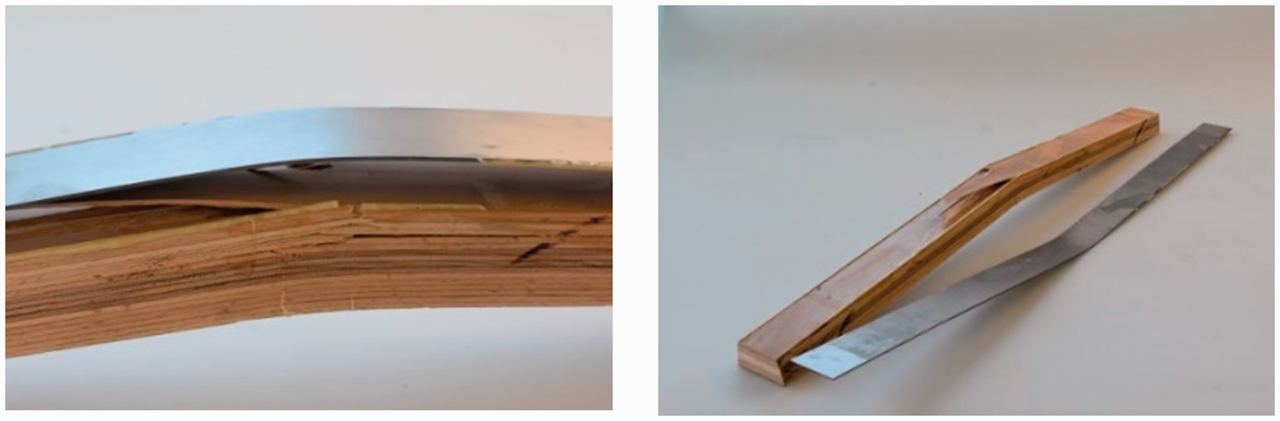
Three-point bending test: failed beam with steel strip (left), wooden beam and steel strip after test (right).
In order to optimize the failure response and achieve functionality of the hybrid material, various measures were taken. High potential was identified in modifying the steel strip. Selective weakening of the steel strip was supposed to prevent sudden failure and detachment as well as provoking plastic deformation of the steel. To achieve this effect, a wide groove was cut into the middle section of the strip.
Figure 9 shows the results of the test. The variant with groove (“Variant 3 – with steel strip and groove”) no longer fails catastrophically and the elongation at failure is significantly increased compared to the variant without groove (“Variant 3 – with steel strip”). The plastic deformation of the strip stabilizes the beam over the entire deformation process, still increasing the force level compared to the wooden beam alone. However, the absolute force level, which is lower compared to the reference, is considered problematic. As can be seen in Figure 9, the maximum force of the reference component is approximately twice as high as the wooden composite beam. Therefore all further tests were carried out without a groove in the steel strip.
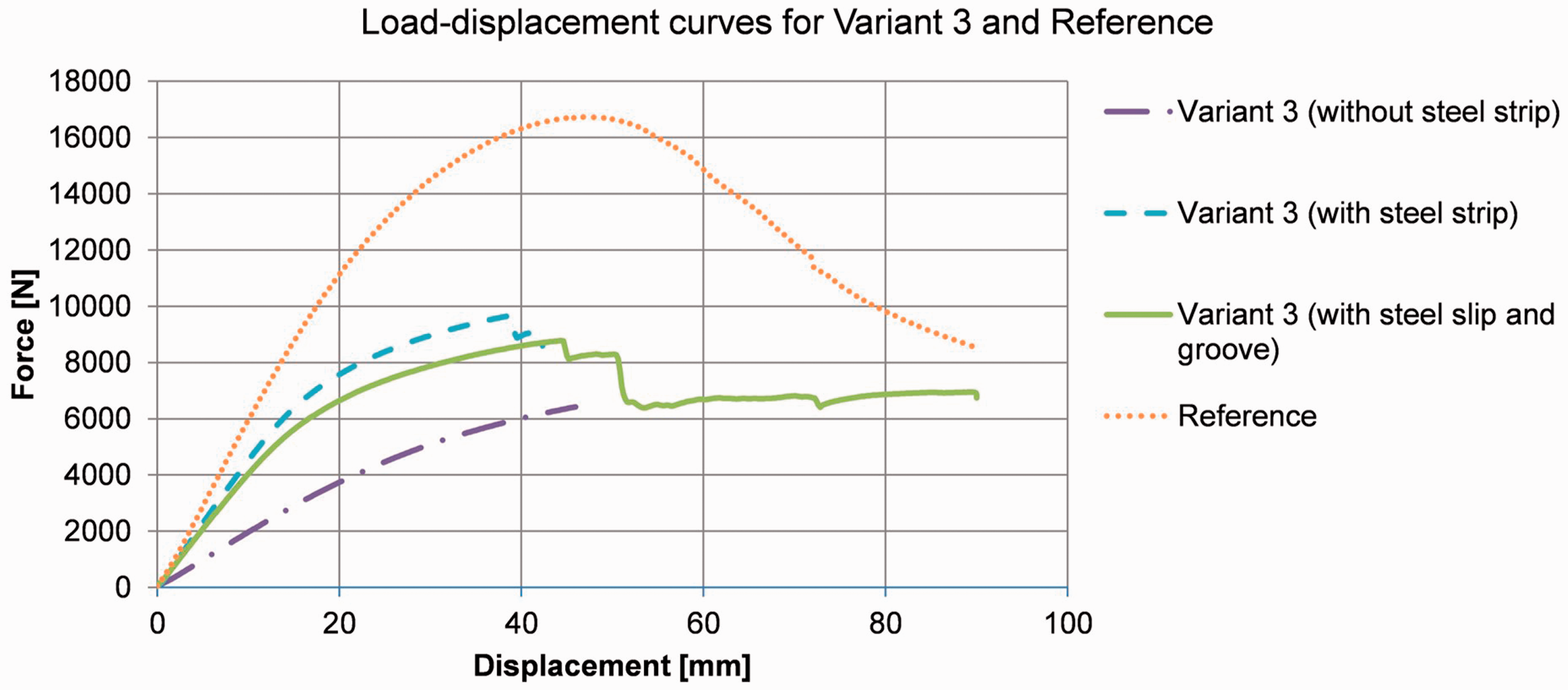
Test of the hybrid beams in the three-point bending test.
Results and discussion three-point bending flexural test (quasi-static with retention forces)
For the further evaluation of the component, quasi-static tests with retention forces were carried out as described in an earlier section. See Figures 10 and 11 for an example of the test results. In Figure 10, the force–displacement curve of the pole is shown. In Figure 11, the force–displacement curves derived from the absorbers are shown. In order to filter the load–displacement curve of the pole, the moving average with a period of 16 was used. By calculating the average of each data point considering the following 15 data points, the moving average is calculated. Using this filtering method, signal fluctuations could be reduced. A similar approach was chosen for the curves shown in Figure 13.
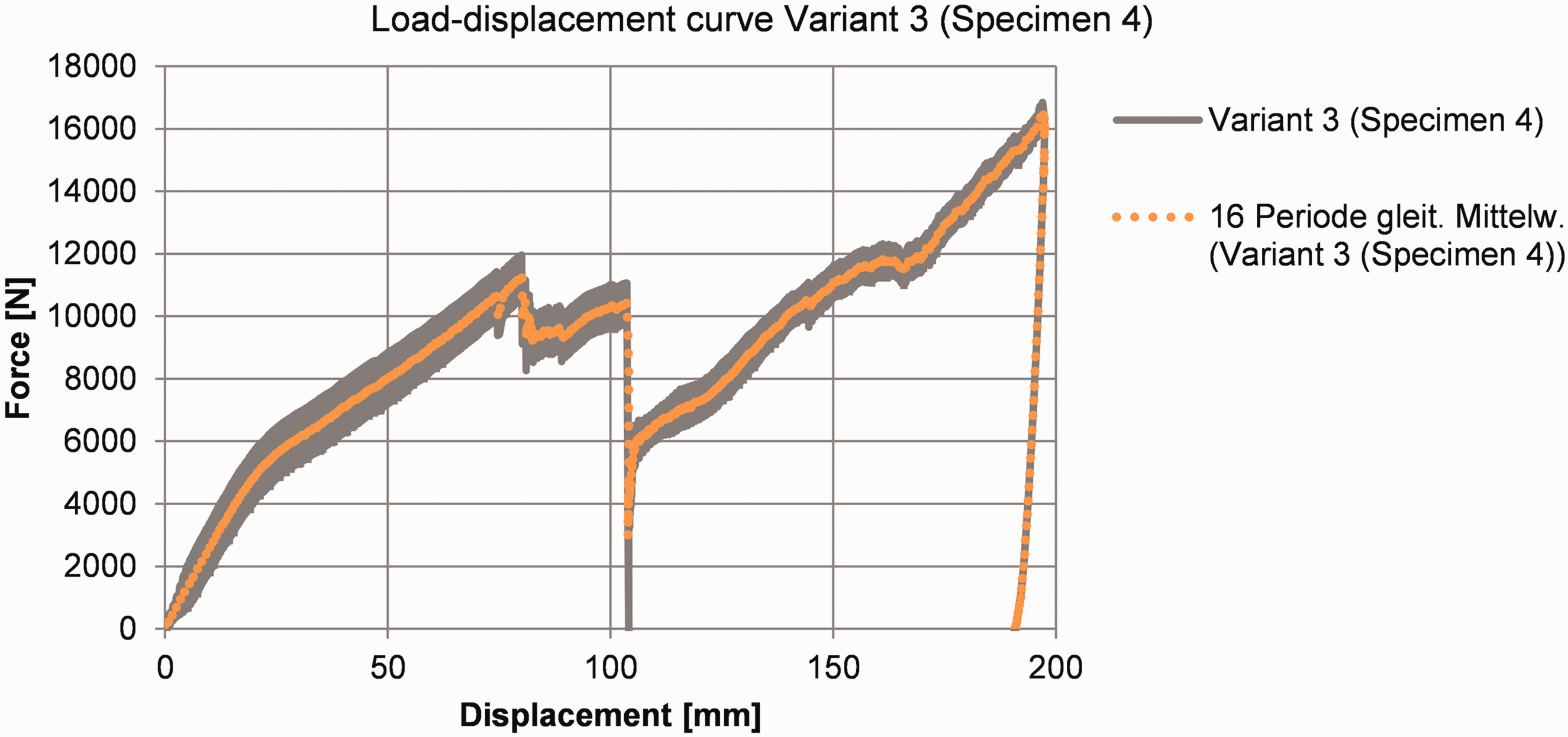
Quasi-static test with retention forces: load -displacement curve “pole”.
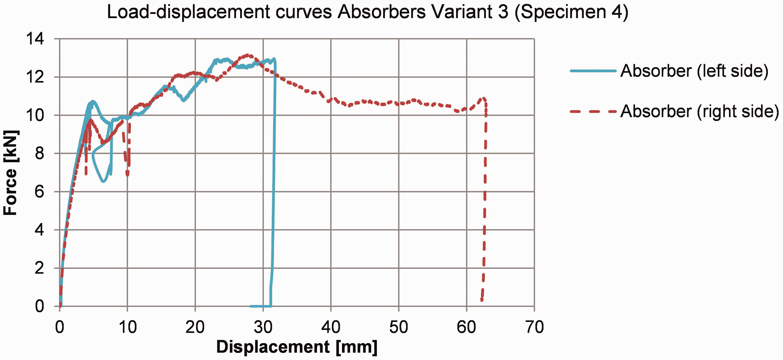
Quasi-static test with retention forces: load -displacement curve of absorbers (left and right sides).
In Figure 10, the displacement up to approximately 100 mm is particularly interesting. In this range, the retention forces show the highest influence on the force–displacement curve. In the three-point bending flexural test without retention forces, a sudden failure occurred earlier (Figure 9). In addition, the forces were lower despite lower support width. At approximately 100 mm the steel strip was detached from the wooden component, so the force level briefly decreases. Since the steel strip remains intact, a further increase in force occurs until the test was completed at 200 mm.
In addition to the force–displacement curves derived from the pole, the force–displacement curves of the two absorber units at the fixing points are shown in Figure 11. The mounting of the beams can be described as “floating”. The experiment discussed here indicates that the right-hand side (Absorber right side) shows a higher displacement than the left-hand side (Absorber left side). There are various possible causes for this asymmetry. These include friction effects, material influence and symmetry-related deviations. Up to a cutting depth of around 10 mm a strong fluctuation in the force and displacement signal could be observed. These fluctuations are caused by stick and slip effects in the cutting mechanism which are transferred to the load and displacement sensors but have no relevant influence on the global force–displacement characteristics.
A detailed breakdown of the absorbed energy can be made based on the measurements. At the connection points (Absorbers), about 1700 J were absorbed, and the energy input through the pole was 2700 J — so about 1,000 J was absorbed in the beam. These considerations provide the starting point for impact-dynamic investigations.
In addition to the influence of the retention forces, the influence of an overlap of 12 mm in the peripheral area was considered in more detail (see Figure 12). It turns out that significantly higher deformations are possible before the steel strip detaches (the first decline in force) if the beam does not overlap at the edge. This is due to the fact that a kind of swivel joint is formed at the connection point without overlapping. However, a freely rotatable connection at the edge does not match the installation position of the beam in the door structure. The reason for the worse results in the case of overlapping is the resulting peeling stress in the edge area: this facilitates detachment of the steel strip.
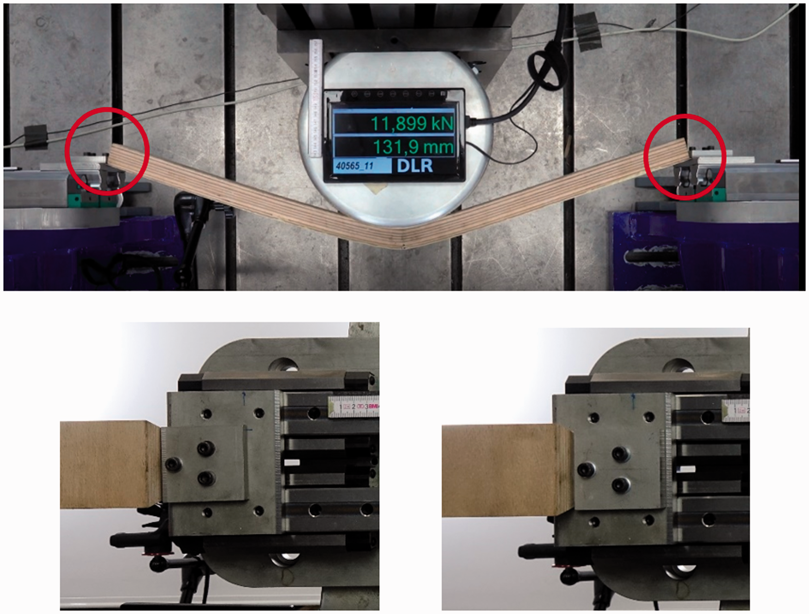
Complete test setup of quasi-static test with retention forces (top), connection in the edge area without overlap (bottom left), connection in the edge area with overlap (bottom right).
Figure 13 shows a comparison of different specimens tested with and without overlap at the edge area. Furthermore, Figure 13 shows that the initial stiffness is slightly lower in the configuration without overlap. However, the influence is comparatively small. Finally, the reproducibility of the results is worth mentioning. The failure response of the beam is dominated by the steel strip. The interface between wood and steel strip is therefore crucial in terms of the performance of the component, as is evident in Specimen 5, where the strip already detached at a deformation of approximately 95 mm. The influence of possible fluctuations in the material characteristics of the wooden beam with regard to component failure, as provided in the material concept, has no significant influence.
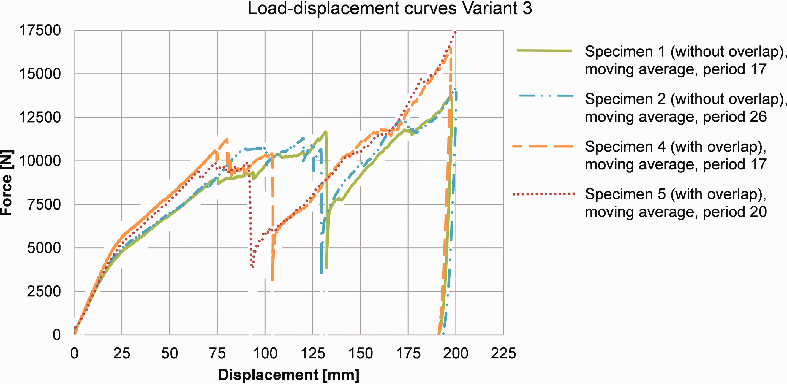
Quasi-static test with retention forces: comparison of load–displacement curves (with/without overlap).
Results and discussion three-point bending flexural test (dynamic with retention forces)
Using the test setup shown in an earlier section, impact-dynamic tests were carried out and filmed using a high-speed camera. The maximum intrusion of the pole was determined based on the video footage. The absolute values are subject to slight uncertainties due to the optical method; however, the main focus here is on comparing the individual beams. Figure 14 summarizes the results and shows them as a percentage deviation from the reference.
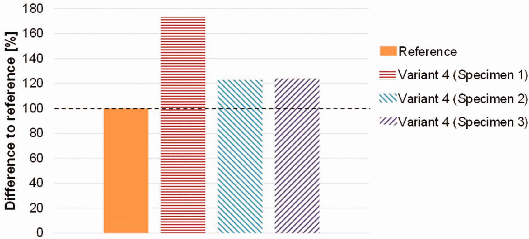
Comparison of intrusion.
As can be seen from Figure 14, the intrusions of the Variants tested were all above the reference. A further result of the tests was that for Variant 5, all beams tested failed at the penetration of the pole. For this reason, the results are not shown in Figure 14. The results of Variant 4 show the influence of the coating system. The images of the high-speed camera show that the steel strip was detached much earlier in Variant 4 with coating system A (Specimen 1) than in Variant 4 with coating system B (Specimens 2 and 3). The earlier detachment of the steel strip leads to a significantly higher level of intrusion. For Variant 4 with coating B, the intrusion was about 21% above the reference.
Regardless the results from the three-point bending test without retention forces (see section “Results and discussion three-point bending flexural test (quasi-static)”) the maximum forces of Variant 4 Specimens 2 and 3 are almost similar to the reference. Two main reasons for the lower intrusion of the reference are the more elastic behavior of the beam and the detachment of the steel strip of the hybrid beam shortly before the pole stops.
Figure 15 shows as an example the force curves at the impactor and at the absorbers. Variant 4 (test item: Variant 4 Specimen 2) shows that the force curve reaches a maximum of nearly 11,000 N. This result is close to the results of the quasi-static tests with retention forces from the section “Results and discussion three-point bending flexural test (quasi-static with retention forces)”. In addition, the absorbers are at a similar force level. Here, the advantage of the cutting principle and the low dependence of the force level on the velocity are again clearly shown (see section “Three-point bending flexural test (quasi-static with retention forces).
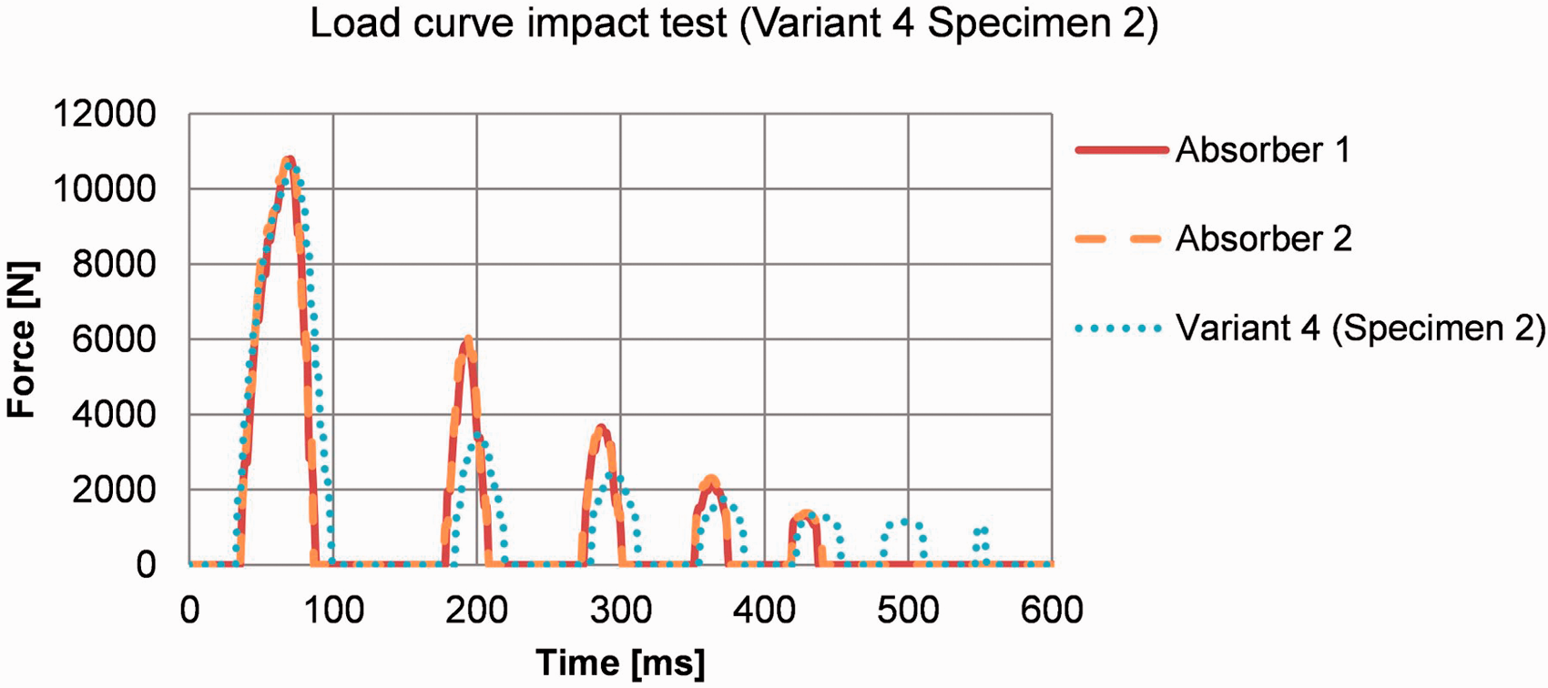
Example of force curve (pole and absorber).
Conclusion
As the results of the dynamic tests show, Variant 4 shows a significantly better performance compared to Variant 5. This is due to the higher number of 0° layers. In contrast to the quasi-static three-point bending flexural tests, the high number of 0° layers has a much less negative effect on the performance of the component. The influence of the “flake-off” of the steel strip observed in the three-point bending flexural tests is significantly reduced due to the retention forces, although even in these tests the steel strip is detached shortly before the maximum intrusion is reached. The tests also show the influence of the coating system and underline the importance of the joint between wood and steel.
The weight of the hybrid-beams is higher than the reference. If only the weights of the hybrid beams with steel strip are compared, the mass for Variant 3 is almost 20% higher than the reference component, and for Variants 4 and 5 nearly 40% higher than the reference due to the high number of adhesive joints. Further options for optimizing the component include a reduction of the beam weight through the use of thicker veneers, the selective milling of areas with low mechanical stress and the use of a wider steel strip to increase the performance. As explained at the beginning, the beam considered represents only a simplified abstraction of a complex component. A final evaluation is therefore only possible with the final component and a comparison of the total weight of the door. First prototypes of the complete door show that the weight is similar to the reference door.
Finally, it can be stated that the hybridization approach is successful. The low elongation at fracture of the wood – which is particularly critical in the crash-exposed component considered here – could be increased due to hybridization. Energy is absorbed by both plastic deformation of the steel strip and failure of the beam. The bending strength is increased, and the properties of both materials are exploited to optimum effect.
Footnotes
Acknowledgements
The authors thank their colleagues from the project “For(s)tschritt” who provided insight, expertise and support through the whole project.
Declaration of conflicting interests
The author(s) declared no potential conflicts of interest with respect to the research, authorship, and/or publication of this article.
Funding
The author(s) disclosed receipt of the following financial support for the research, authorship, and/or publication of this article: This study was supported by the German Federal Ministry for Economic Affairs an Energy (BMWi) through the project management department of TÜV Rheinland.