
Abstract
In this paper, a mathematical model of a rotor-bearing system is presented. The model includes modal elastodynamics of a flexible rotor as well as the in-plane radial dynamics of the bearing with a flexible outer race. Elastodynamics of the flexible shaft utilises a solution based on Green's function to provide a computationally efficient approach. The flexible bearing outer race is modelled using Timoshenko beam theory. The system model also includes detailed lubricated contact mechanics of balls-to-races contacts with viscous friction. Therefore, the rotor-bearing analysis represents a detailed multi-physics tribodynamics and modal elastodynamic responses of the system which closely represents broad-band vibration response of such systems in practice, an approach not hitherto reported in the literature. It is also demonstrated that the outer race flexibility changes the location of the stability orbital centres, as well as the spread of limit cycle vibrations. Furthermore, it accentuates the occurrence of multiples of ball pass frequency. The importance of integrated system dynamics and lubricated contact mechanics is highlighted, showing that although the elastodynamic response of the rotor's flexible elements may not be clear in the acquired vibration signal, its effect on energy efficiency of the system can be quite important.
Keywords
Introduction
Bearing supports are often the limiting factor for the performance of any machine and mechanism which they are a part. The key issues of concern with bearings are thermal stability,1–3 wear and fatigue of rolling mating surfaces,4–8 and noise and vibration.9–12 During operation, the rolling elements within a bearing undergo complex motions such as rolling and sliding relative to the raceway grooves, as well as convergence and separation of the bearing rings. 13 Therefore, use of a bearing dynamics model is a prerequisite to any investigation of its performance, such as reliability, structural integrity, fatigue, wear, and operational efficiency.
Sunnersjö 14 was one of the first to investigate the effect of applied inertial forces using a two degree-of-freedom (2 DOF) bearing dynamics model. Rahnejat and Gohar 15 improved on the work of Sunnersjö 14 by including lubricated balls-to-races contacts under various regimes of lubrication. This was further extended by Aini et al. 16 in a 5 DOF ball-bearing model including radial, thrust, and moment loading. For rolling element bearings, the effect of roller tilting, yawing, and squeeze film motions as well as lubricated contacts have been taken into account by various researchers.17–20
Additionally, the lubricated contact of rolling elements to races in bearings is often subjected to high shear, resulting in generated heat and lubricant non-Newtonian traction. Mohammadpour et al. 21 extended the previous lubricated contact dynamics analysis of Aini et al. 16 to include these effects in their bearing dynamics analysis model. A recent detailed thermal model was also presented by Alfares et al. 22
Another salient practical feature for modelling of shaft and bearing systems is the flexibility of bearing rings or the bearing housing which influences the dynamic performance of shaft and bearing systems.23–27 The flexibility of the rotor itself also affects the rotor-bearing system dynamics.28–31 In fact, there are a host of practical features which may be incorporated in bearing dynamic analysis. Consequently, there has been a plethora of research in the area of rolling element dynamics, with most focusing on certain specific aspects.
This paper presents a 2 DOF bearing dynamics model, which integrates the transient elastodynamic response of the bearing's flexible outer race with elastohydrodynamics of balls-to-races contacts. In this manner, both the localised Hertzian deflection and global elastic deformation of the bearing's outer ring are taken into account. The outer race of the bearing is considered an elastic thick complete circular ring, because in practice the radius-to-width ratio of the outer ring is less than 10 and according to Chidamparam and Leissa 32 this requires the use of a Timoshenko beam model. Therefore, elastodynamics of the flexible ring is based on Timoshenko (or Timoshenko–Ehrenfest) thick ring theory, 33 thus including the effect of rotational bending and shear deformation. The numerical solution of full-bearing dynamics with a flexible ring is quite time-consuming. Consequently, an analytical model for the elastodynamic response of the shaft is developed, which is based upon Green's function approach. Therefore, realistic elastodynamics of a flexible rotor-bearing system with non-Newtonian piezo-viscous lubricated contacts is presented, an approach not hitherto reported in the literature.
Model description
Rotor-bearing model
Figure 1(a) is a schematic representation of an elastic rotor supported by a pair of deep groove ball bearings. Figure 1(b) shows a deep groove ball bearing, where the instantaneous dynamic load carried by the ball complement is determined by the lateral excursions of the shaft centre from that of the support bearings in the transversal radial x and y directions.
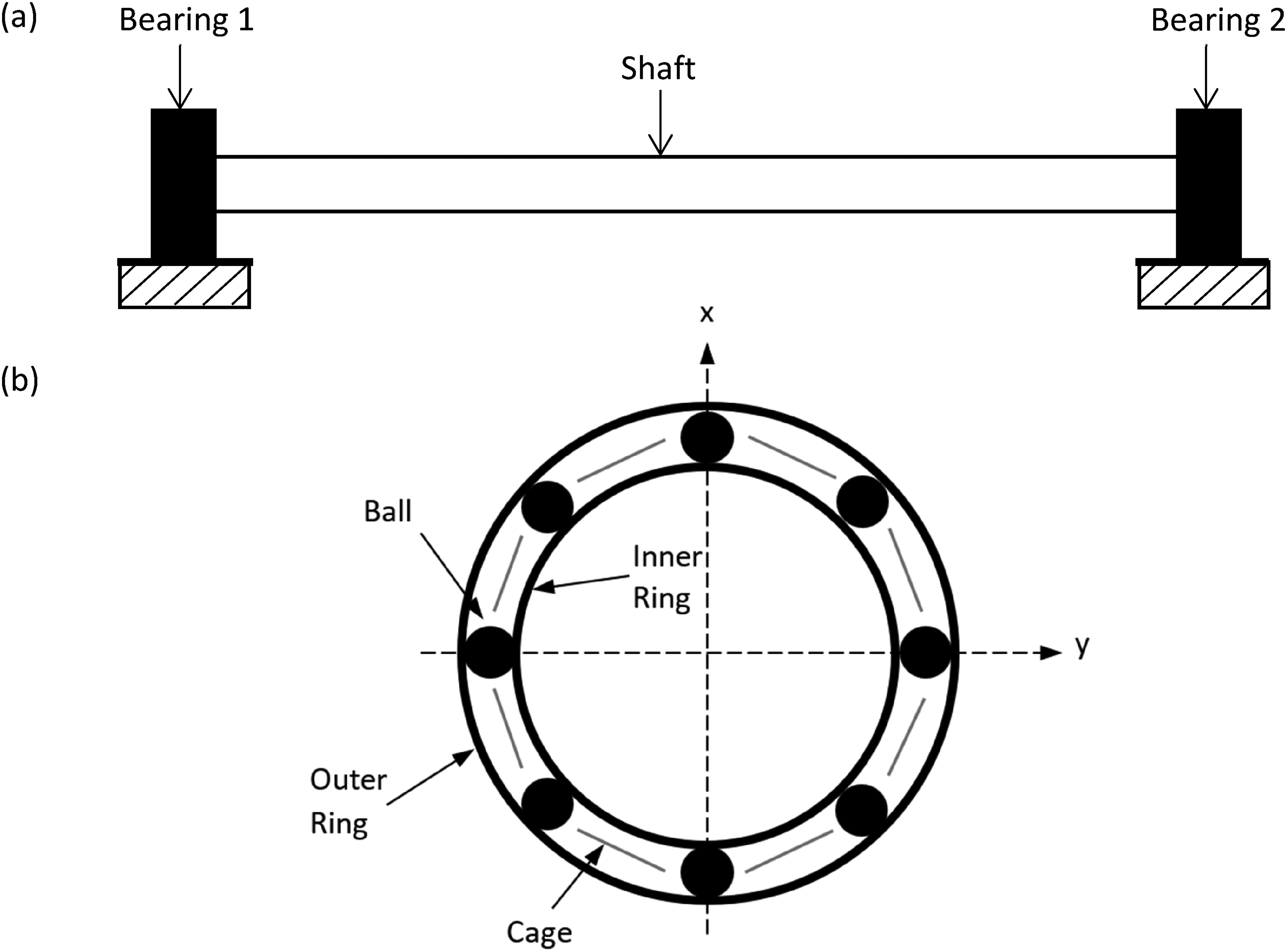
(a) Overview of rotor system, (b) 2 degree-of-freedom deep groove ball bearing dynamic model.
For the 2 DOF bearing dynamics model the following assumptions are made:
The inner and outer bearing races are considered to be perfectly circular. The balls are considered to be perfectly spherical and have identical diameters (i.e., there are no off-sized rolling elements). The balls are considered to be massless compared with the supported shaft and bearing rings and remain equi-pitched around the bearings. Bearings are subjected to radial transverse loading only. Thermal effects are neglected (these will affect dimensional stability, interference fitting and preloading of the bearing,1–3 as well as lubricant rheology in the contact).
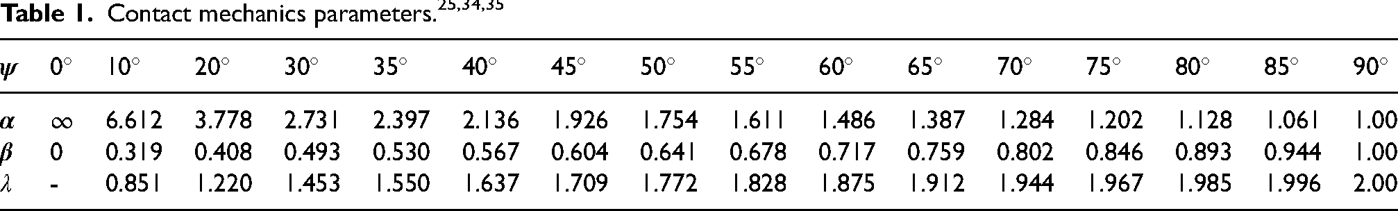
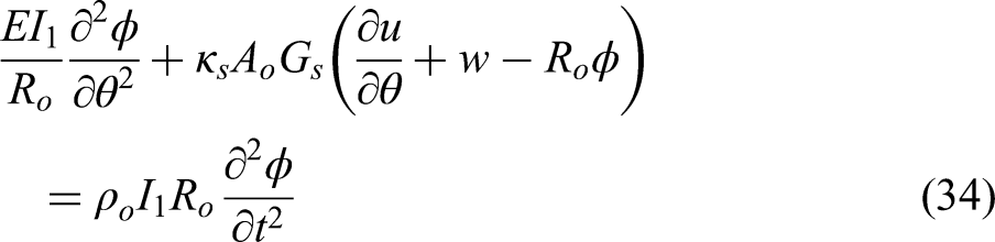
34
These assumptions lead to a 2 DOF bearing model described in the study by Rahnejat and Gohar15,35 for a radial deep groove ball bearing. The equations of motion become:
where

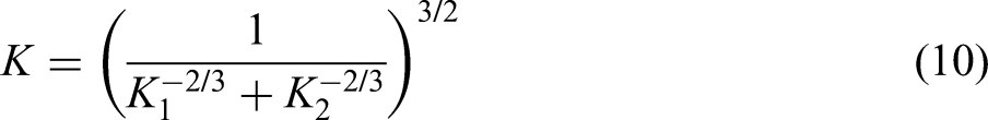
where K is the contact stiffness nonlinearity,
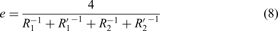
The localised contact deflection of the i-th ball,

where

The combined contact stiffness nonlinearity, K, of any of the ball-to-inner and ball-to-outer races contacts are determined as36,37:
where 1 denotes the contact with the inner race and 2 for the outer race.
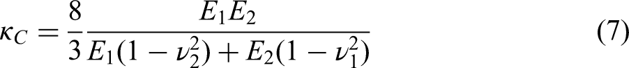
where E and
where

The effective contact stiffness for a ball-to-races contacts becomes:
The maximum Hertzian contact pressure for the i-th contact becomes
38
: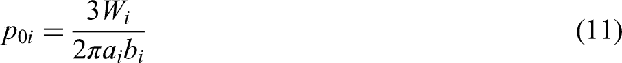
where the semi-major and semi-minor half-widths for the elliptical point contact footprint are, respectively: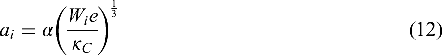

To determine the film thickness for lubricated contacts of the balls to raceway grooves one can use an extrapolated oil film thickness equation as initially shown in Rahnejat and Gohar.
15
These expressions are obtained by regression of many numerically predicted results based on the variation of a number of dimensionless parameters which represent a broad range of representative operating conditions in contacts subject to EHL. In the current study, the expression obtained by Hamrock and Dowson
39
is used: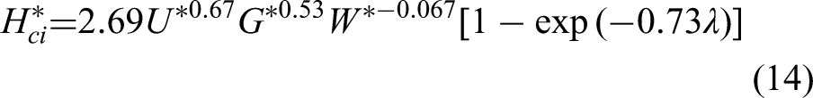
where 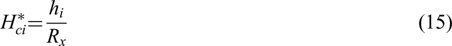
in which:
The dimensionless parameters in equation (14) are: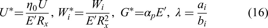
where
Having obtained the lubricant film thickness for all the balls-to-races contacts, the viscous shear stress in all contacts can be obtained as Gohar and Rahnejat
38
: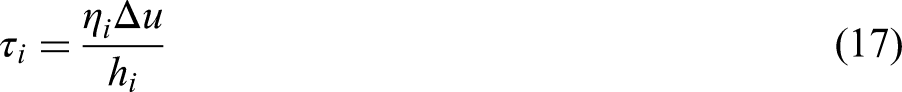
where for the assumed isothermal solution in the current analysis the effective lubricant viscosity in the i-th ball's contact is adjusted for the mean contact pressure, 
where for the i-th contact the mean contact pressure is:
Friction is mainly generated by sliding in the contact, promoting viscous shear of the lubricant. The sliding velocity 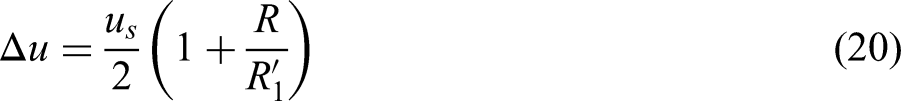
where
The shear stress in equation (17) is under Newtonian shear of the lubricant. With increased contact load and contact sliding, the lubricant traction may exceed the Eyring shear stress,
42
where the lubricant behaviour is termed non-Newtonian. Thus
43
:
where
Assuming smooth contacting surfaces, friction is mainly generated by the viscous shear of the lubricant. Thus, for the i-th elliptical point contact
38
:
and the associated instantaneous power loss becomes: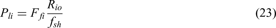
where
The total bearing power loss is:
Elastodynamics of the rotor
The flexibility of the supported rotor is included in the 2 DOF system dynamics model. It is assumed that the shaft is free at both ends and subjected to excitation forces at the bearing supports. The equation of motion for such an elastic shaft is given as:
where 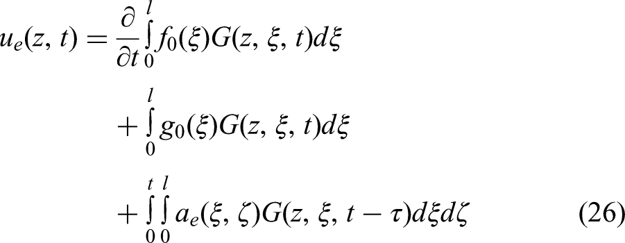
where 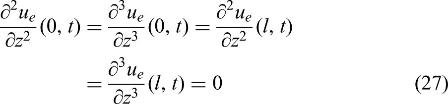
the Green's function becomes: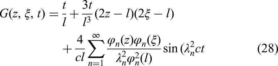
where 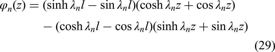
in which,
One of the advantages of using this approach over the conventional modal analysis method is that it simultaneously provides the natural frequencies and mode shapes. Note that the first two terms in the expression for the Green's function are associated with the zero eigenvalue with two orthogonal functions 1 and
The applied force for the rotor shown in Figure 1 has the following general piecewise profile: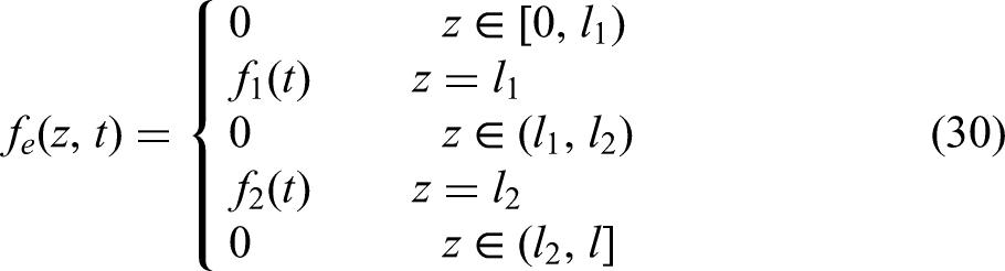
where 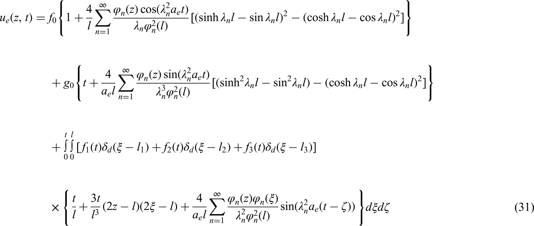
where
In-plane elastodynamics of the bearing outer race
The global modal deflection of an outer flexible bearing ring is included in the 2 DOF bearing dynamics model (i.e.,
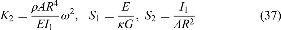
The coupled in-plane equations of motion for a thick ring segment representing the outer race of a ball bearing, including shearing deformation and rotary inertia are obtained as
45
: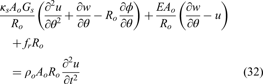
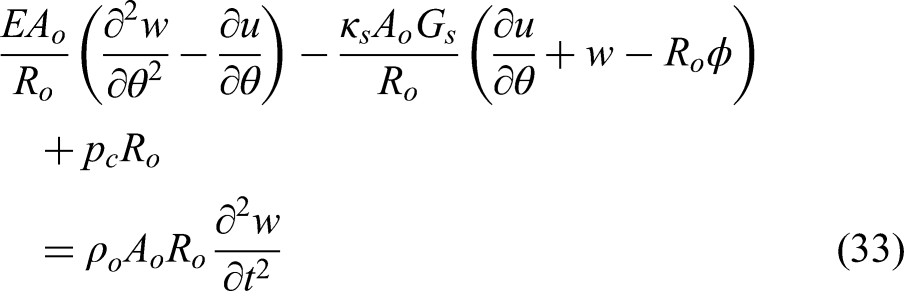
where
Method of solution
Two multi-physics models are utilised in the current analysis. The first model (the rigid bearing ring model) includes a 2 DOF bearing dynamics model with a flexible rotor. This model assumes that the bearing races are rigid. The second model (the flexible ring dynamics model) removes the assumption of a rigid outer raceway by including the elastodynamics of a flexible outer race. The solution procedure is depicted by the flowchart of Figure 2.
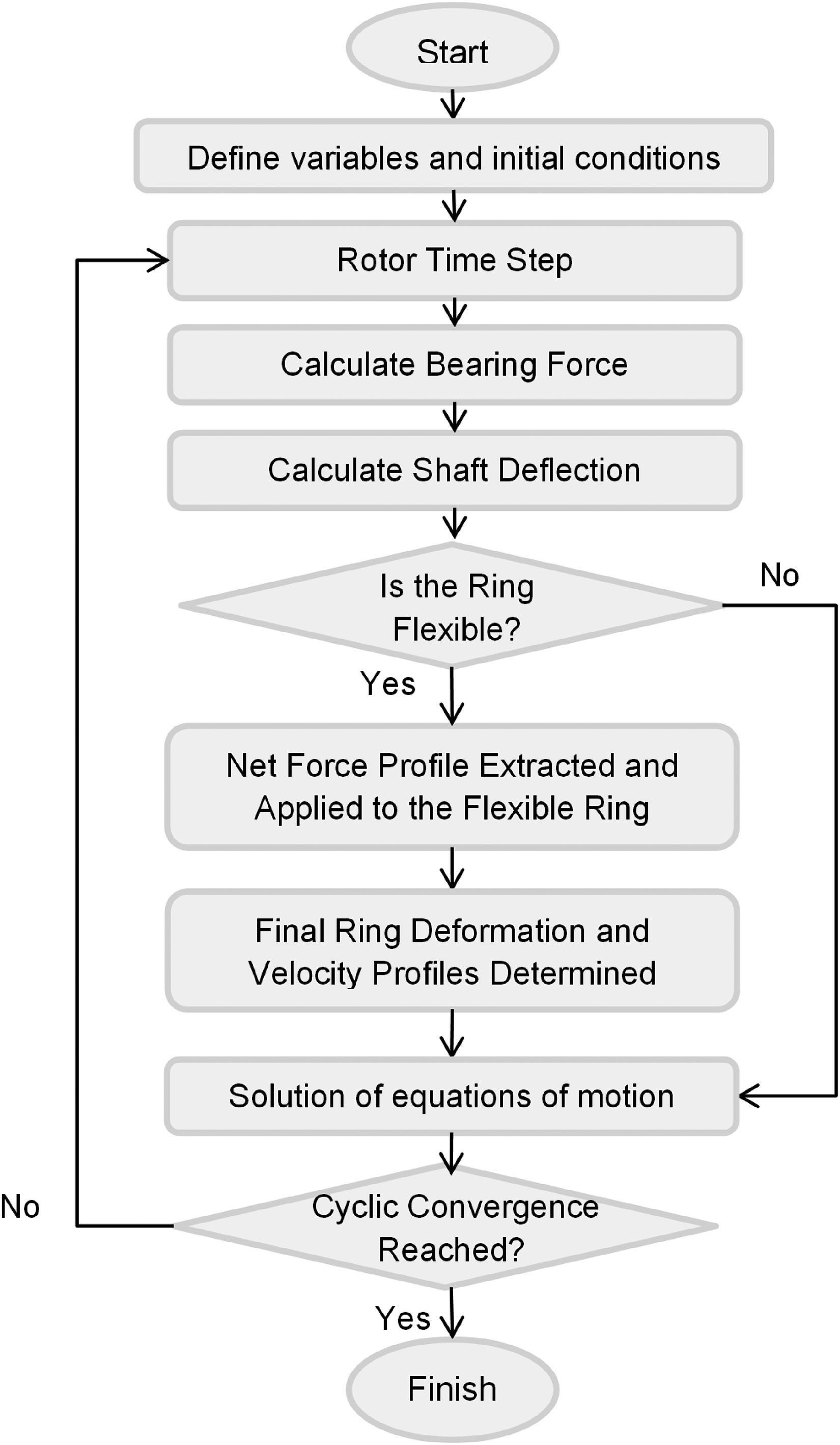
Solution procedure.
Results and discussion
Rotor model validation
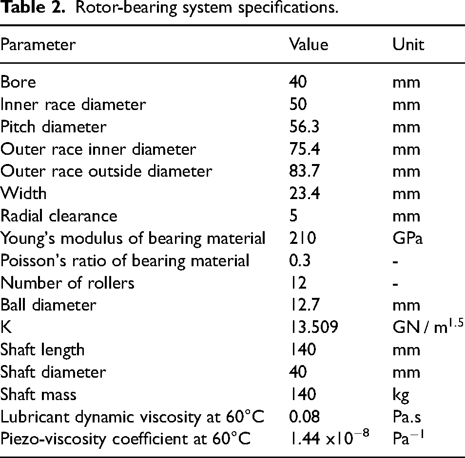
The specifications of the rotor-bearing system are listed in Table 2. All the balls-to-race contacts are assumed to remain in compression throughout the balls’ orbital motion, thus guarding against a number of undesired phenomena such as ball skewing, rattling and balls-cage collisions. The radii of curvature of the raceway grooves provide a contact conformity of 7% and an angle of
Rotor-bearing system specifications.
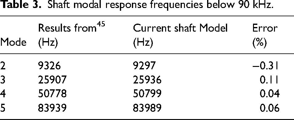
The component-level predicted response frequencies for the flexible shaft and the flexible bearing outer raceway are first obtained prior to the determination of system level (i.e., the rotor dynamics) analysis. The predicted frequencies for the flexible shaft are compared with the analytical flexible vibration frequencies given by Rao
45
as: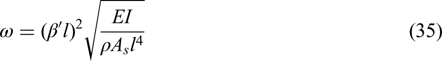
Shaft modal response frequencies below 90 kHz.
For a thick flexible ring, the vibration frequencies are given by Rao
45
as: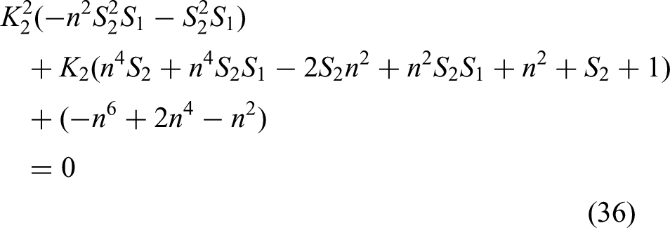
The predicted numerical results are compared with their analytical counterparts in Table 4.
Flexible bearing outer ring modal frequencies below 90 kHz.
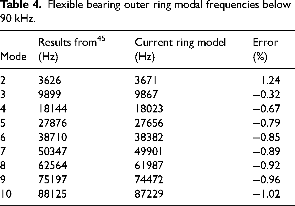
The results obtained for both the flexible shaft (Table 3) and the flexible bearing outer ring dynamics (Table 4) show excellent agreement with the calculated analytical frequencies in Rao. 45
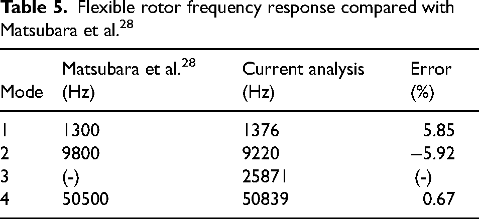
The next stage in model validation is comparison with the numerical work of Matsubara et al. 28 In this case, the rotor system comprises a flexible shaft, bearing supports, and a rigid outer raceway, subjected to a sinusoidal load of 60 N magnitude at its ends. The resonant frequencies of the rotor are presented alongside the predictions provided by Matsubara et al. 28 Good agreement is found between the predictions of the current model with those in Matsubara et al. 28 as shown in Table 5. It is noted that the model proposed by Matsubara et al. 28 utilised a piece-wise linear approximation of the ball-race contact spring non-linearity in the bearing. In the current model the need for a piece-wise linear approximation has been eliminated. Therefore, the current model predicts frequencies that are similar to the model presented by Matsubara et al. 28 with differences predominantly caused by the piece-wise linear approximation in Matsubara et al. 28
Flexible rotor frequency response compared with Matsubara et al. 28
Nonlinear effects induced by a flexible outer ring
Simulations are carried out at a constant rotational frequency of 13.3 Hz (cage frequency). The dynamic responses of the rotor are compared for the rigid ring and flexible ring models of the bearings. To identify the impact of ring flexibility on rotor dynamics, the system responses are investigated using time histories, phase-plane diagrams, and Fast Fourier Transformation (FFT). Figure 3(a) and (b) shows the variations in the shaft displacements with rigid and flexible bearing outer rings in the vertical, x- and horizontal transverse y-directions, respectively. Ring flexibility mainly affects the displacements in the x-direction (Figure 3(a)). The slower oscillations follow the shaft rotational frequency in both directions. A protuberance appears near the minimum response amplitude in the x-direction for both cases due to the interactions of the rolling elements with the flexible ring and shaft. The fast oscillations of the shaft undergo noticeably larger amplitudes in the vicinity of this protuberance, indicating greater interactions between the flexible ring and shaft responses in this region. In the y-direction (Figure 3(b)), the amplitude of the rapid oscillations is rather negligible in comparison to that of slow oscillations.
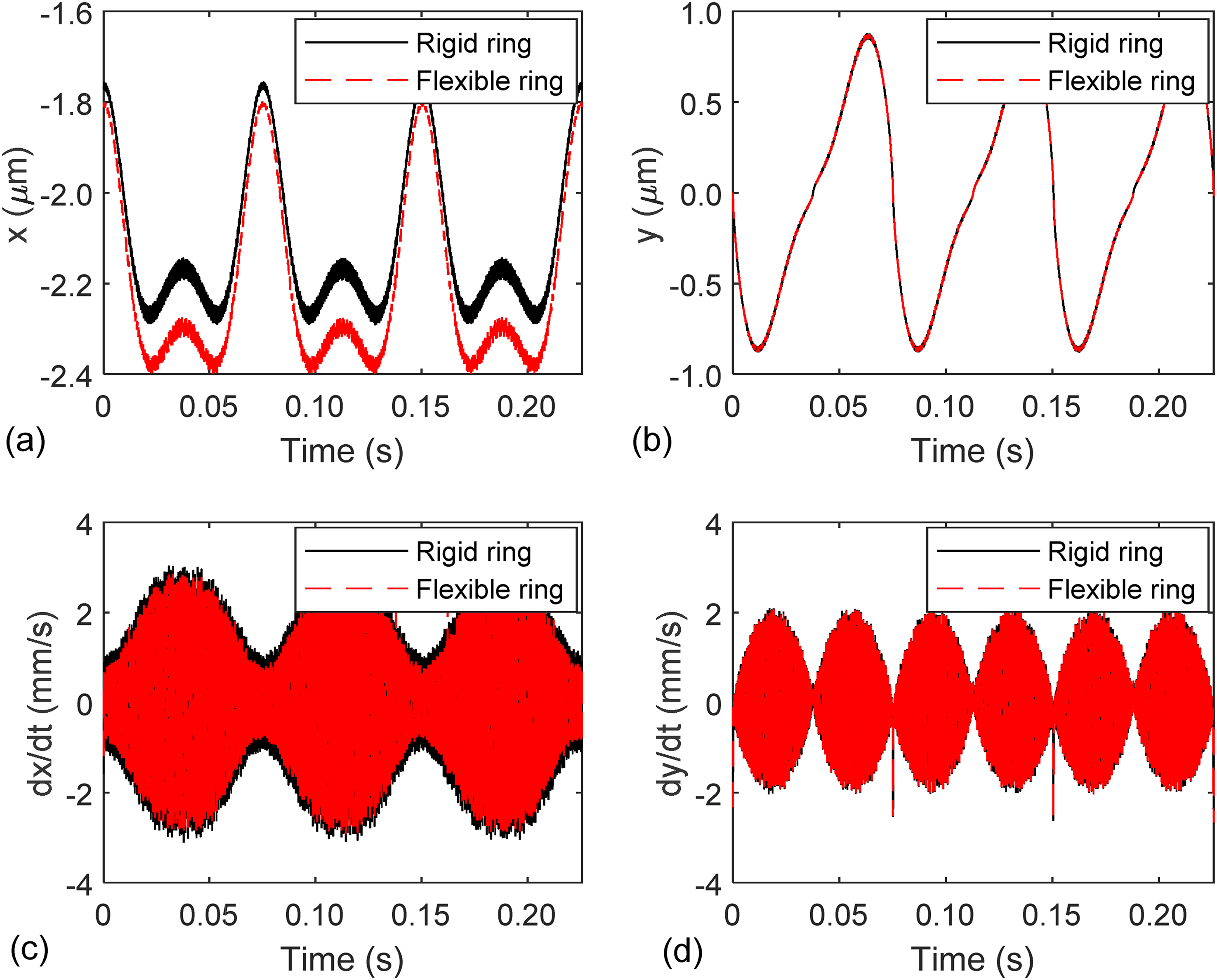
Comparison of shaft vibration time histories for a rigid and a flexible bearing outer ring model: (a) vertical displacement, x, (b) horizontal displacement, y, (c) vertical velocity, dx/dt, and (d) horizontal velocity, dy/dt.
The variations in the shaft velocity are largely influenced by the fast oscillations in both directions (Figure 3(c) and (d)). The velocity for the case of an assumed rigid ring shows marginally larger variations in the x-direction. The lower velocities for the case of a flexible ring are due to a small increase in the amplitude of displacements of the shaft, which has a larger excursion at the same rotational frequency. The fast variations of the velocity amplitudes in the x-direction are constrained by a slow frequency envelope related to the shaft rotation. The envelope wave in the y-direction fluctuates at twice the shaft rotational frequency (Figure 3(d)). A spike appears at around 0.075 s when the shaft undergoes maximum displacement in the x-direction (Figure 3(d)). At this position, the interference between the shaft and rolling elements reduces and the rolling elements-to-races contact loads attain their minimum value. Hence, the spike can be related to a sudden transition of the shaft over the rolling element bearings. In the y-direction, the rigid and flexible ring models are largely identical due to the fact that the shaft is unloaded in this direction.
The transverse x-y displacement plot of the bearing centre with and without a flexible outer ring is shown in Figure 4. The results in this figure show a slight increase in the amplitude of vibrations for the flexible bearing outer ring. This is due to the deflection of the flexible ring, causing waviness of its surface, affecting the contact of the ball complement in their orbital motion. In turn, this increases vibration of the shaft centre as an excursion from the geometric centre of its bearing support.
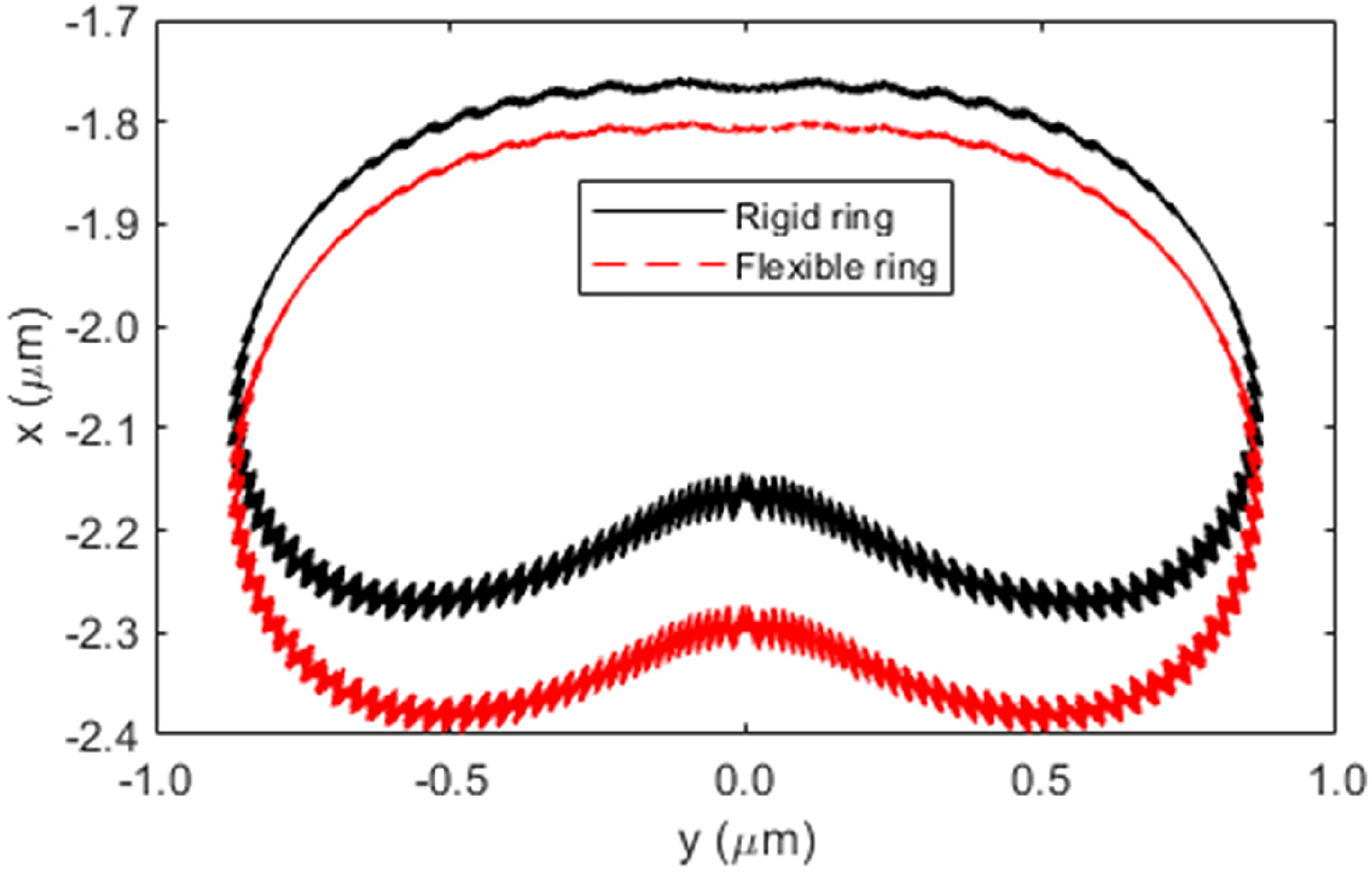
x–y displacement diagram of shaft centre with rigid and flexible bearing rings models.
The stability of the shaft vibrations is studied through phase-plane diagrams. The cloud representation of the phase-displacement diagram is shown for the shaft vibrations using the assumed rigid bearing outer ring model (Figure 5). The shaft is located at the maximum and minimum amplitudes in the x direction in the regions (A) and (C), respectively (Figure 5(a)). Region (B) shows the shaft transitions between the regions (A) and (C). The phase-displacement diagram shows multiple limit cycle trajectories (cloud cyclone). The behaviour of these trajectories conforms to the findings in the time histories of shaft vibrations. Centre of each limit cycle represents the point of stability with respect to the centre of the shaft cross-section at each position. The limit cycles about these centres are associated with the flexible shaft vibrations. These centres, however, displace with the rigid body motion of the shaft. Hence, the limit cycles are spread in the x-direction. The shaft has a minimum energy level in the region (A). Therefore, the cloud limit cycle shows a smaller spread/domain. In region (C), the flexible shaft vibrations and their interaction with the orbital motion of the rolling elements are significant, increasing the excitation energy. Hence, the limit cycles fluctuate with a larger spread. This behaviour indicates that the shaft is less stable when it modulates with the motion of the rolling elements. The limit cycle near
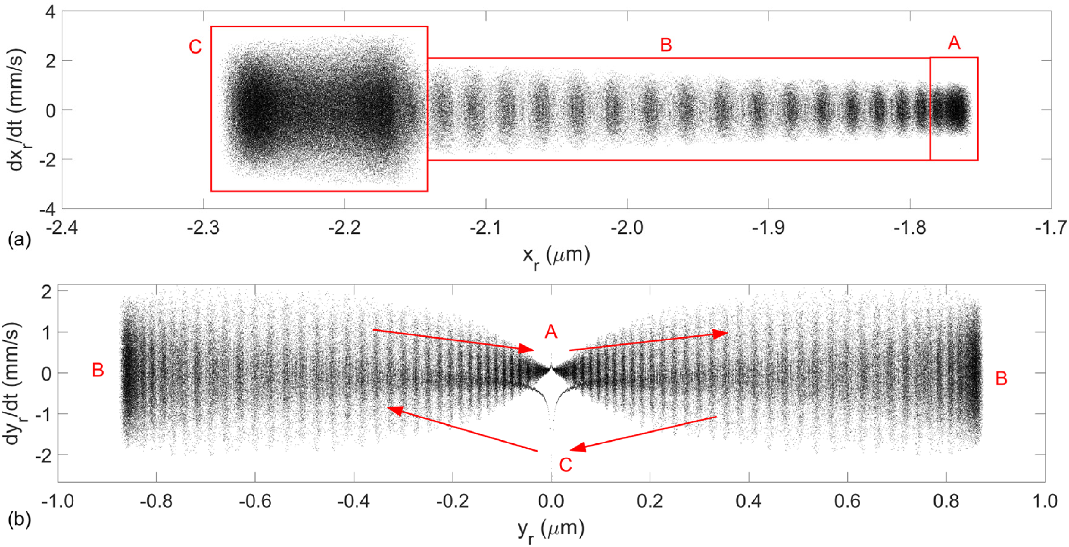
Phase-displacement cloud diagrams of shaft vibrations with rigid ring: (a) vertical components, dxr/dt-xr, (b) horizontal components, dyr/dt-yr.
Figure 6 shows the phase-plane diagrams for the flexible bearing outer ring model. The behaviour of the shaft in this flexible model is largely similar to that of an assumed rigid shaft. In the x-direction, the transition regions are stretched, indicating larger displacements. The limits of regions (A) and (C) are also displaced to lower
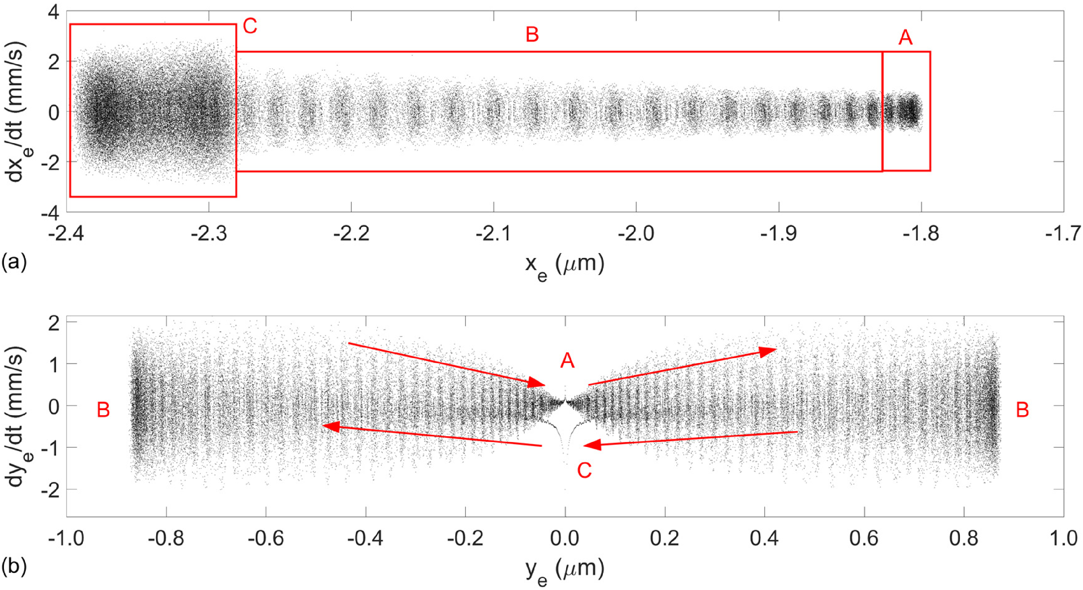
Phase-displacement cloud diagrams of shaft vibrations with flexible ring: (a) vertical components, dxe/dt-xe, (b) horizontal components, dye/dt-ye.
Time history and phase-displacement diagrams clearly show the large-scale displacement and stability behaviour of the rigid and flexible ring models. However, these are insufficient to provide detailed differences between the responses of the two models. Hence, fast Fourier transformation is carried out. Spectra response of shaft vibrations are compared for the rigid ring and flexible ring models (Figure 7). The first five mode shapes of the elastic shaft are included in the simulations. The first mode represents the rigid mode of the shaft and modes 2–5 are related to its elastodynamic responses. The frequency content due to shaft modal vibrations is identical between the rigid and flexible ring responses. In both cases, the shaft modal frequencies are the main contributors to the spectra
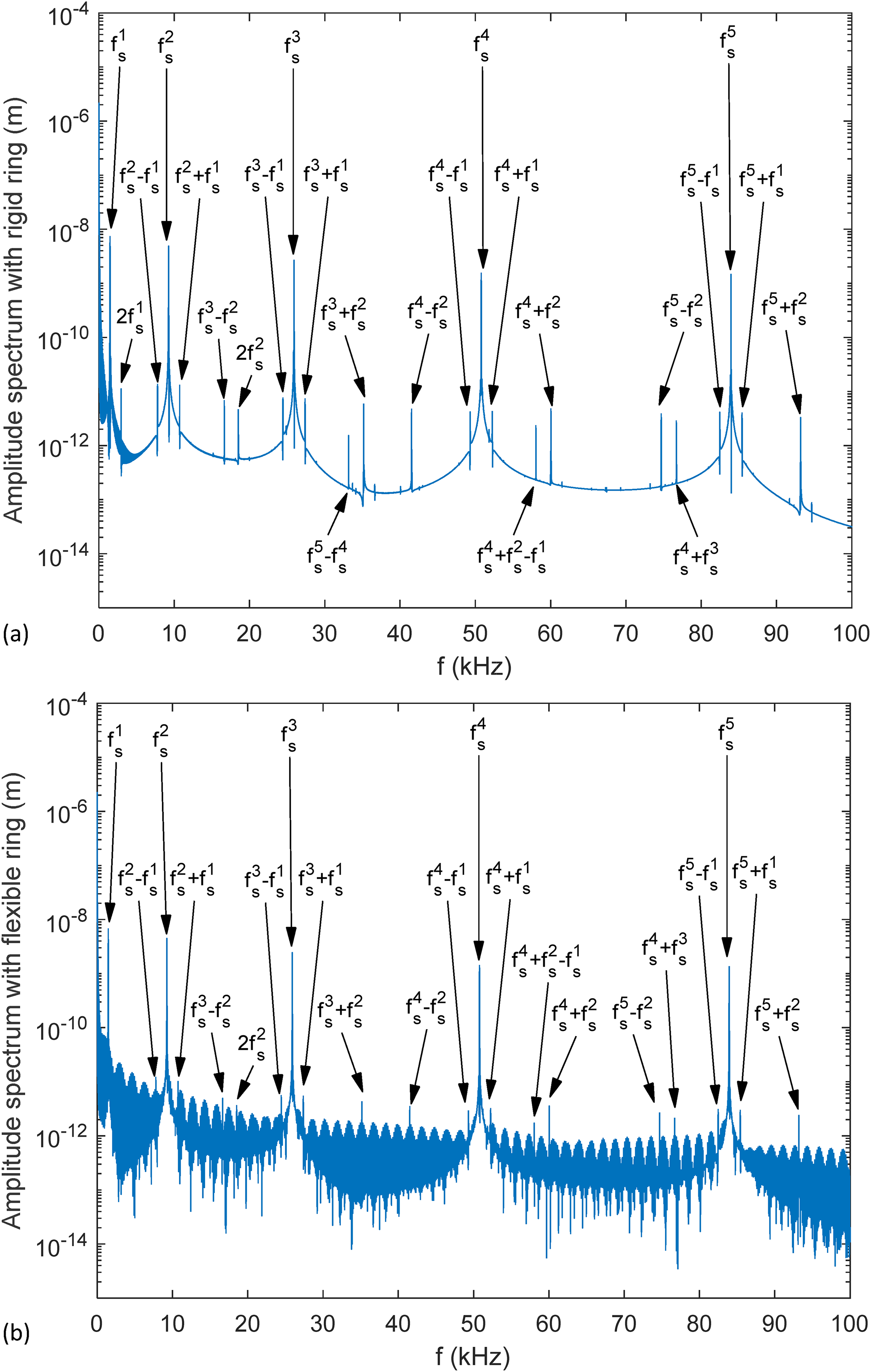
Spectrum of shaft vibrations in the band: 0–100 kHz: (a) rigid ring and (b) flexible ring.
To better understand the root cause of the noise signatures in the flexible ring model, initially, the response spectra is investigated in the lower frequency range: 0–5 kHz (Figure 8). This frequency domain is selected because it only includes the first rigid mode of the shaft 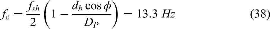
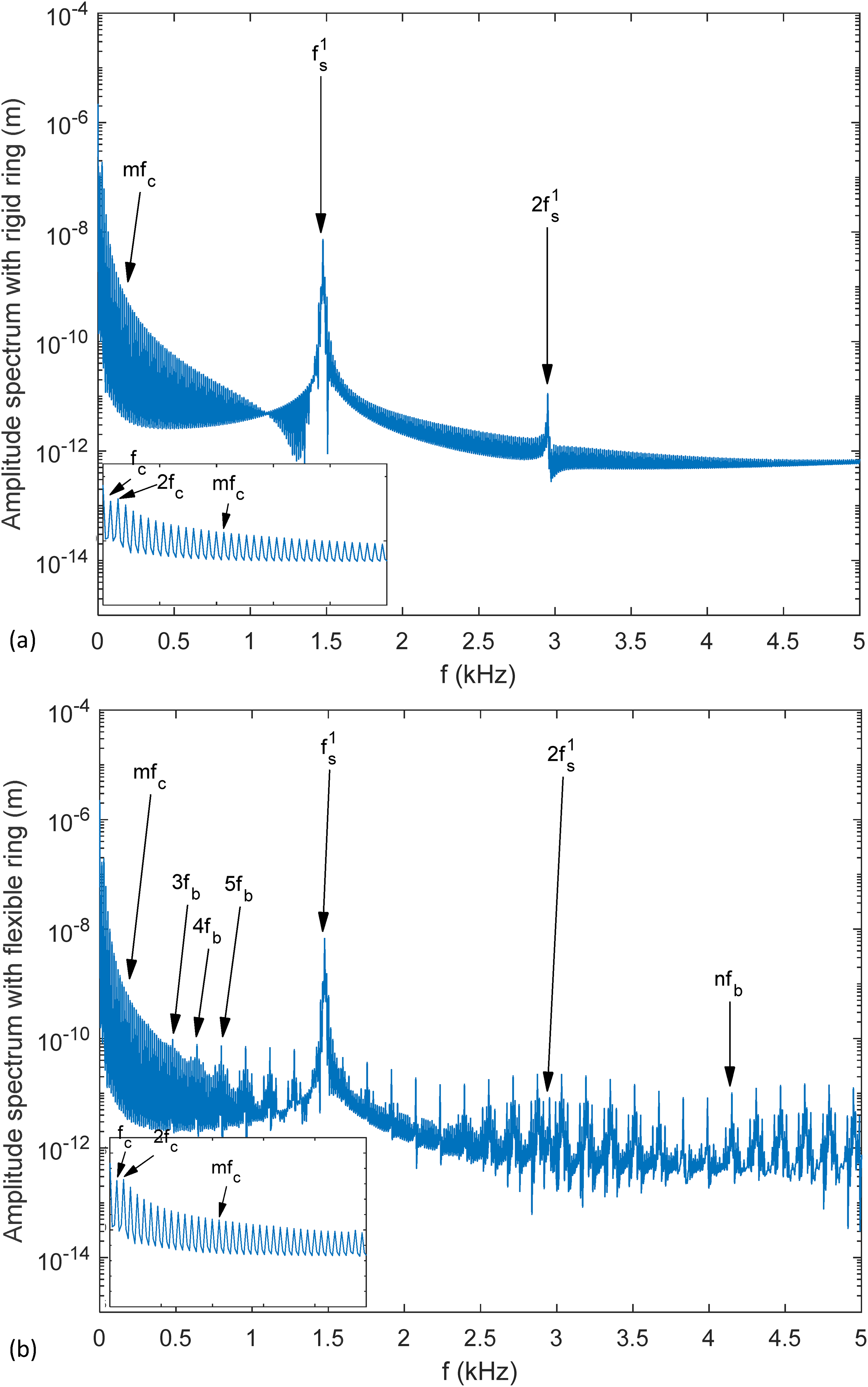
Spectrum of shaft vibrations in the band: 0–5 kHz and the zoomed-in views between 0 and 0.5 kHz: (a) rigid ring and (b) flexible ring.
where
The higher orders of cage response largely disappear at higher shaft vibration frequencies near 5 kHz. Another key bearing induced response is the ball-pass frequency (
This spectral contribution is inherent in rolling element bearing response due to changes in the dynamic stiffness as the ball complement undergoes its orbital motion. This effect is termed variable compliance effect.9,14,15,41,46 The modal responses of a flexible bearing ring exacerbate the variable compliance effect. These observed effects are similarly amplified across the low to high-frequency ranges (0–100 kHz) (Figures 7(b) and 8(b)). Figure 7(b) clearly shows contributions at multiples (harmonics) of the ball-pass frequency occurring regularly in the spectrum. To investigate these responses, a frequency range between 31 and 39 kHz is randomly selected (Figure 9). Additional frequency content clearly follows the multiples of the ball-pass frequency. These higher harmonics and their modulations with other spectral contents are always present in the rotor-bearing as shown in the acquired vibration spectra,10,11,41,47–49 or in the various reported dynamic analyses.14–16,21,25,35,50,51 The fluctuations in the amplitudes of these frequencies occur at the rigid body modal frequency of the shaft (
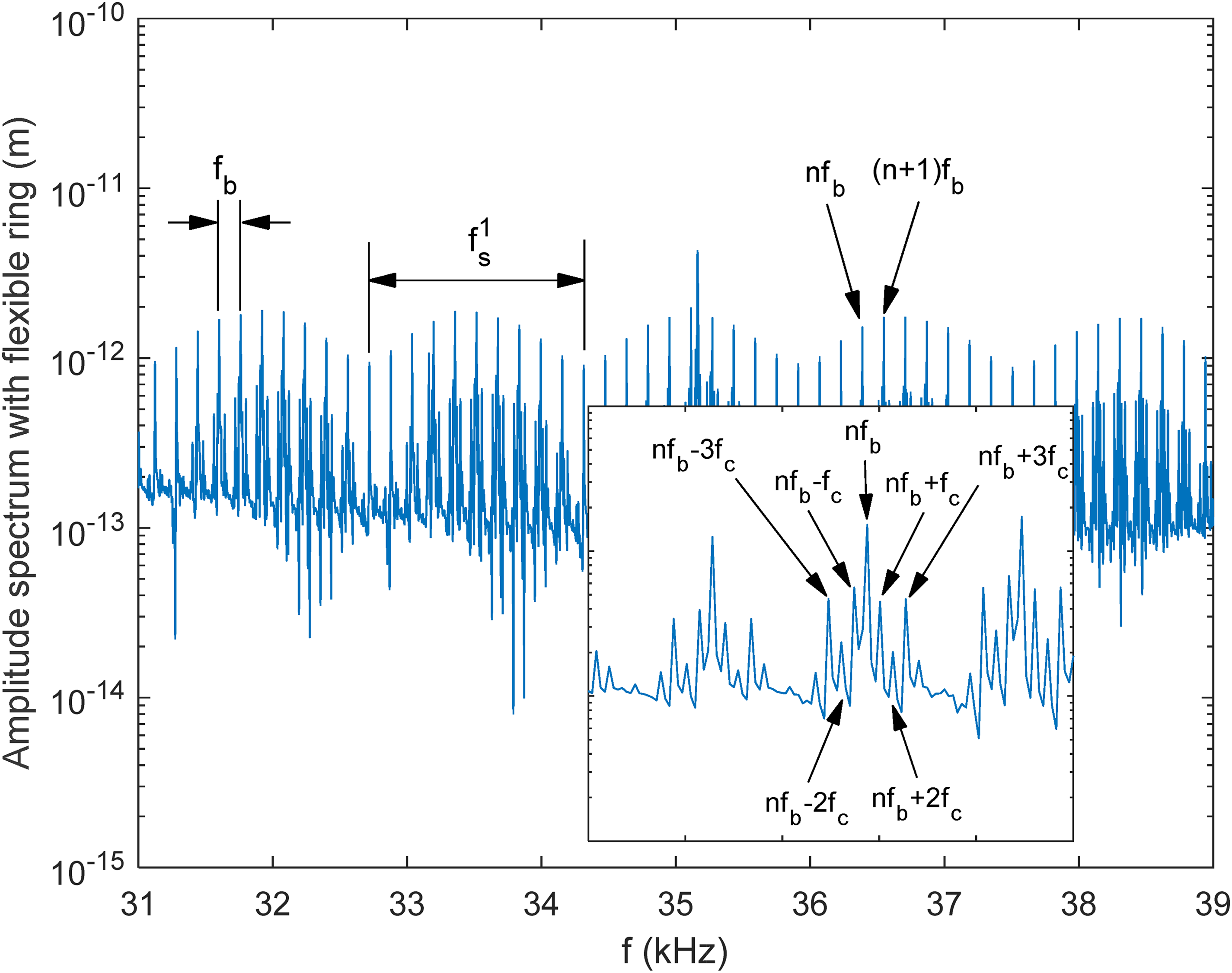
Influence of ring flexibility on amplification of higher orders of ball-pass frequency, nfb, and its interactions with the first rigid mode of shaft, fs1.
Assessment of bearing performance
There have been very few lubricated bearing dynamics models15,16,21,52,53 as this adds to the complexity of the analysis. However, incorporating lubricated contact dynamics into the analysis makes for realistic conditions, mimicking actual practice. In the current analysis, smooth rolling surfaces are assumed with sufficient radial interference so that the predominant regime of lubrication in the balls-races contacts remains elastohydrodynamic. With high loads and shear the lubricant can undergo non-Newtonian behaviour as described in section 2.1. Figure 10(a) shows the lubricant film thickness variation in a ball-race contact for a cage cycle for both cases of an assumed rigid as well as a flexible outer race. There is a reduction in the lubricant film thickness owing to the elastodynamics of the flexible bearing ring, constraining the gap in the contacts. Although the reduction in the film thickness is only very marginal, it increases the viscous contact friction as shown in Figure 10(b).
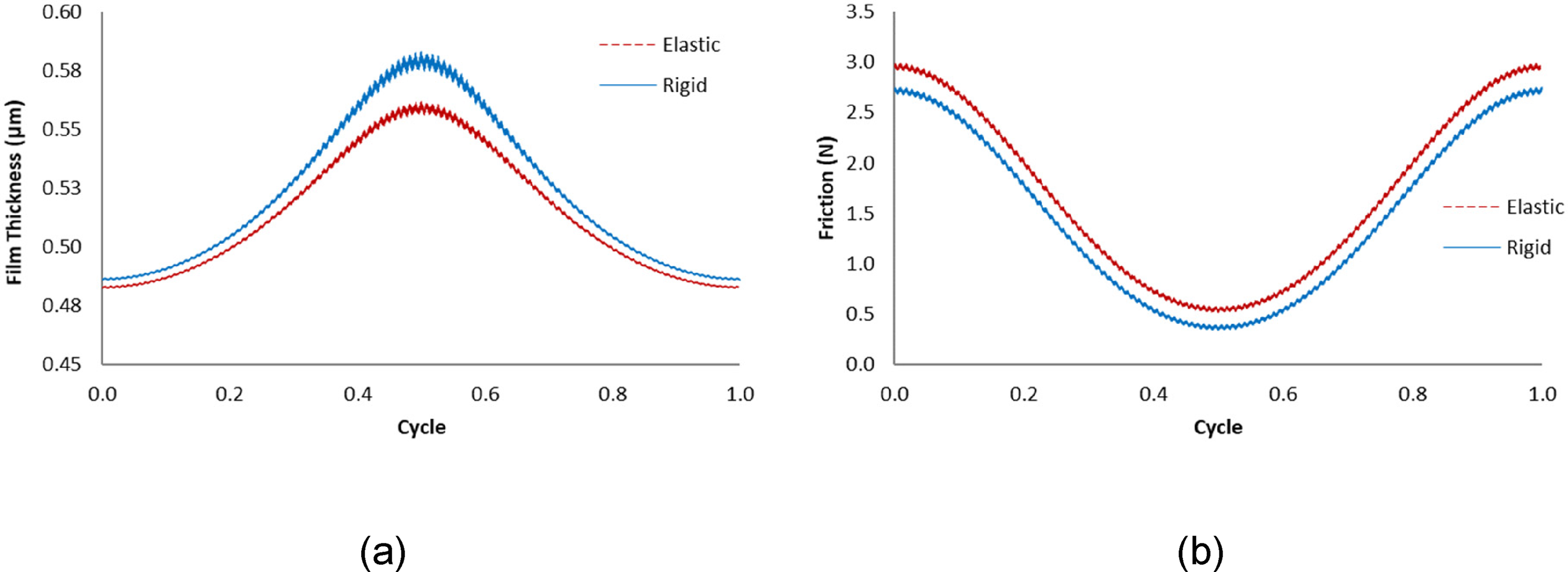
(a) Minimum film thickness and (b) friction for a ball in a single orbital motion.
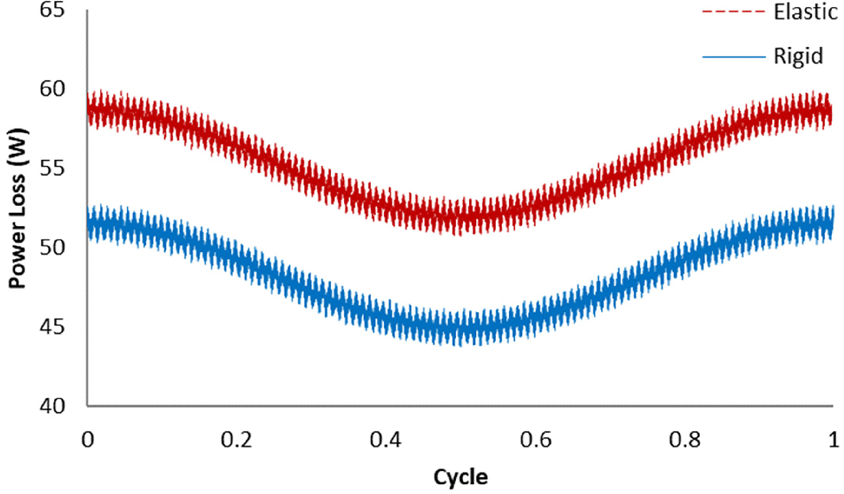
The overall effect of increased viscous friction is an increase in the overall frictional loss from the bearing as calculated using equation (24). This increased cyclic bearing frictional loss is shown in Figure 11. Friction is mainly generated by viscous shear of the lubricant and the sliding velocity of the balls to the races as the rolling elements roll and slide relative to the races due to the existence of a curvilinear ellipse in space. 41 The ring flexible elastodynamics influences the motions of the races and, therefore, the contact friction. There are many bearing cycles (cage rotations) in any application with 90–95% of all machines and mechanisms making use of rolling element bearings. Therefore, bearing losses occur as the result of elastodynamics of bearing supports, which contribute to energy consumption and inefficiency of the machines worldwide. 54 It should be noted that rolling element bearing power losses are significantly lower than that of other forms of bearings and contacting pairs such as gears.
Predicted power loss.
Concluding remarks
There has been a plethora of studies of rotor-bearing systems. These have included various important features, among many, in their analyses. However, very few studies have included the effect of rotor structural flexibility with lubricated contact dynamics including flexible outer race or housing. The current paper's main claim to originality resides in the integration of these practical aspects in rotor-bearing dynamics. The noted broad spectral response in vibration monitoring, not often presented in dynamic analysis, is obtained in much detail here. The combined investigation of shaft vibrations through time history, stability phase-displacement diagrams and FFT graphs clearly highlight the main shaft contributions and the secondary noise effects, originated from the ring flexibility on the nonlinear and transient vibrations of the flexible shaft. Ring flexibility has less impact in the shaft stability. However, it changes the location of the stability centres and spread of limit cycle vibrations. Moreover, ring flexibility amplifies the multiples of ball pass frequency even in the highest spectral region. These higher harmonics of ball pass frequencies induce cage responses in the form of side-band signatures, which would otherwise disappear at higher frequencies for the rigid ring model. Thus, including the elastodynamics of the rotor elements in the system vibration analyses would allow the identification of root causes of the noise and vibration in the system. Furthermore, it is shown that although the vibration signatures of such elements may not be clear in an acquired signal, their effect on the system energy efficiency can be quite significant. Therefore, shaft-bearing system vibration in its broad spectral response should be studied with the presence of lubricated contacts and frictional energy dissipation considerations. This detailed analysis shows that system dynamics and lubricated contact mechanics are closely intertwined and affect the overall system performance.
Footnotes
Acknowledgements
The authors gratefully acknowledge the financial support of the Engineering and Physical Sciences Research Council (EPSRC) extended to the Centre for Doctoral Training in Embedded Intelligence under the grant reference EP/L014998/1.
Declaration of conflicting interests
The authors declared no potential conflicts of interest with respect to the research, authorship, and/or publication of this article.
Funding
The authors disclosed receipt of the following financial support for the research, authorship, and/or publication of this article: This work was supported by the Engineering and Physical Sciences Research Council, (grant number EP/L014998/1).
Nomenclature
Appendix
Discretisation of equations (32)-(34) provides the mass and stiffness matrices for the in-plane ring dynamic behaviour.
The in-plane inertial forces for a circumferential position i, representing instantaneous point of contact of the i-th ball take the form:
Hence, the mass matrix [
where the mass matrix constants are:
The in-plane elastic force for the same point i, takes the form:
where the stiffness matrix constants are: