
Abstract
To provide a suitable rotation rate for different machining processes, a single machine tool spindle should work over a wide range of speeds. This study considered the effects of speed on dynamic behaviour of ball bearings and combined the fatigue life model and ball bearing internal load distribution model to determine the appropriate preload. First, the influence of speed on internal load distribution and ball bearing contact angles was analysed. The preload was calculated using a ball bearing internal load distribution model. Next, assuming constant bearing fatigue life, the theoretical preload curves were determined using the fatigue life model by changing the reliability factor. Finally, at low speeds, the maximum designed preload (design value) was set as the initial preload. With the increase in speed, the optimum preload was hierarchically obtained within the internal region between the theoretical preload curves. An experimental test rig for the optimum preload of ball bearings, which can automatically adjust the preload, was developed. The proposed method for determining the optimum preload was verified using the measured performance indicators, including the temperature, motor currents, and vibration of ball bearings. The results showed that the optimum preload suggestion made the test ball bearings exhibit excellent behaviour.
Introduction
Currently, high-speed machining tools are often required to perform in a wide range of applications. High-speed milling, heavy cutting at low speed, and light cutting at high speed are often performed with the same machine tool spindle. High-speed spindles used in these machine tools often use ball bearings with an initial axial preload. Over high speeds, a high preload increases the frictional heat generation in the ball bearings. The heat could potentially enhance thermal expansion in spindle components and reduce the bearing life span. 1 Over low speeds, a lower preload decreases both the stiffness and the metal cutting removal rates. 2 Ball bearings are considered expendable components, though they affect the performance of the machine tool spindle.3–5 Therefore, a proper preload can improve the bearing performance and ability of a high-speed machining tool over a wide range of applications.6,7
A literature survey indicated that many studies have been conducted to determine the required preload for ball bearings. In previous studies, the fatigue life model was used to establish a required preload.2,8–11 Ozturk and Guo researched the dynamic and stability behaviour of ball bearings through experiments and analysis. They showed that modelling values are close to the experimental results.12,13 Many examples were also uncovered that analysed the thermal effects of bearing preload and presented several approaches to decreasing the associated thermal error.14–16 Researchers have used numerical methods to calculate ball bearing parameters, including applied load, stiffness, and contact angles.17–20 Several authors have also studied a variable preload device, which focused on using an automatic variable preload system that changed as the speed changed.21–23 Finally, rolling contact fatigue in ball bearings has long been recognised as a complex issue that has a deep impact in this field because it displays phenomena at various scales. Its presence depends on the testing conditions, such as contact pressure, temperature, number of revolutions, and steel cleanliness. 8
However, in the literature, very few studies were related to the quantitative analysis of preload for ball bearings. In addition, the experimental methods used to determine a proper preload were lengthy, and the results were not necessarily correct. In this article, a fatigue life model and ball bearing internal load distribution model were combined to optimise the ball bearing preload based on lifetime performance reliability. The influence of speed on the internal load distribution and ball bearing contact angles was also analysed. After obtaining the internal load, the optimum preload could be determined by changing the reliability factor within the fatigue life model. The proposed method to determine optimum preload was verified using measured performance indicators, such as the temperature, motor currents, and vibration of ball bearings. The results showed that the optimum preload contributed to ideal behaviour in the test ball bearings.
Assembly of test rig
Experimental system
Figure 1 illustrates a schematic of the experimental system that was used to verify the optimum preload for ball bearings. The test shaft is driven by a motorised spindle and is supported by ball bearings (B7007C), which are acted on by hydraulic parts. The hydraulic pressure induces displacement in the axial direction, pushes the outer ring of the rear bearing, and eventually transfers this displacement to the inner ring of the rear bearings through the shaft. Therefore, the displacement caused by hydraulic pressure is converted into axial force. The lubrication system generates an oil–air mixture. The outlets for the oil–air mixture system are connected to three separate channels: front bearings, rear bearings, and load bearings. Throughout the entire process, the amount of oil–air mixture remains constant, which keeps the lubrication system steady. Figure 2 shows the ball bearing instrumentation for the test rig. The highest speed achieved by the motorised spindle is 20,000 r/min. The speed of the motorised high-speed spindle is controlled by a frequency converter. Subsequently, the axial preload and radial loads are adjusted by a proportional hydraulic system. Data on the speed, preload, current, vibration, and temperature are automatically sent to a centralised controller.
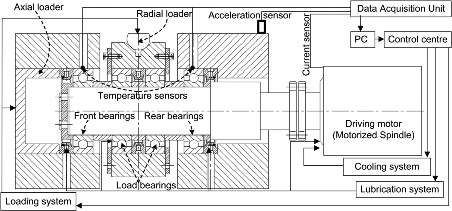
Schematic of test rig for the ball bearings.
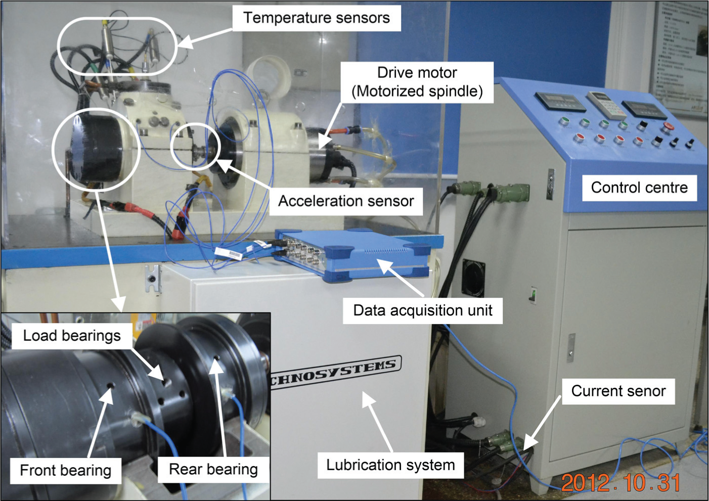
Test rig layout.
Instrumentation
Vibration in the ball bearing outer ring is measured by an acceleration sensor. The bearing temperature is measured using thermocouples (PT100). The spindle speed is confirmed by the rotational frequency. The speed of the test shaft is determined by the vibration spectrum of the ball bearings. The axial and radial preload are proportionally adjusted by hydraulic pressure, which is controlled by a PC. The spindle current is measured by a current clamp.
Analysis of bearing axial preload
Fatigue life is an important indicator of safe operation and is affected by the internal loading of a ball bearing. In this section, the fatigue life model and ball bearing internal load distribution model were combined to determine the optimum preload. Under a constant theoretical service life condition, the fatigue life model calculates the optimum preload curve by changing the reliability factor in Figure 3.
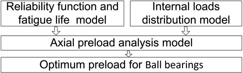
Diagram of the theoretical analysis method.
Reliability functions and fatigue life model for ball bearings
The Lundberg and Palmgren (L.P.) 24 fatigue life theory and accompanying formulas were a significant development in rolling bearing technology. Combining the Waloddi and Weibull distributions results in an assumption that fatigue cracking starts from material weak points below the rolling contact surfaces. In 1949, fatigue failure theory was published for solids. 25 Based on Weibull’s theory, L.P. presented the basic equation
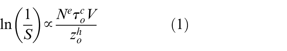
where
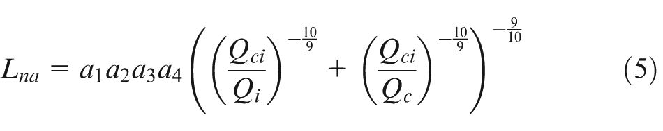
Non-standard loading conditions can be used to estimate bearing fatigue life. To apply increased reliability effects, non-standard materials, lubrication, and contamination, a simple approach using cascading reliability factors has been most frequently taken and is recommended by Zaretsky 9 and by various bearing manufacturers. This approach uses the following equation (Zaretsky 9 )
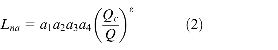
where
Values of
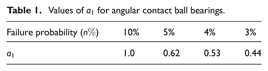
In equation (2),
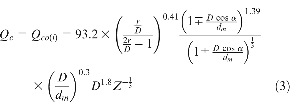
where, for the inner raceway,
The multiplicative factor concept employed in equation (2) has been used since the 1960s when the first improvements in bearing steel were made and the role of lubricant films in bearing fatigue endurance was discovered. The lifetime formula used in many bearing applications has substantially exceeded predictions. 11
Internal load distribution of ball bearings
Figure 4(a) shows the displacement of a ball bearing inner ring relative to the outer ring due to preload
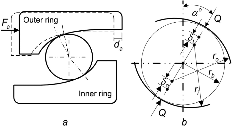
The displacement of a ball bearing due to preload(a), Ball raceway contact after a static load is applied (b).
Under zero load, the centres of the raceway groove curvature radii are separated by a distance BD, where
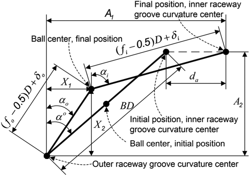
Positions of the ball centre and raceway groove curvature centres.
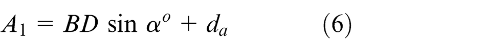
The axial distance of the raceway groove curvature centre at any ball position is
The radial displacement between the loci of the groove curvature centre at any ball location is
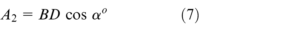
where
Jones introduced two variables,
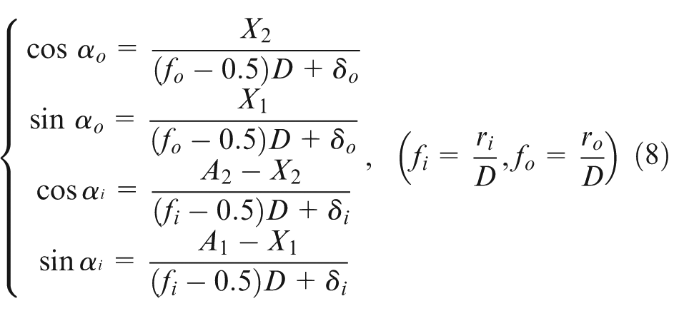
where
Consider the plane passing through the bearing axis with the centre of a ball located at any azimuth. If outer raceway control is approximated at a given ball location, the gyroscopic moment of the ball is resisted entirely by frictional force at the ball’s outer raceway contacts, as shown in Figure 6, where the inner and outer ball friction force
where
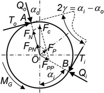
Loads acting on a ball.
For the steel balls, the centrifugal force,
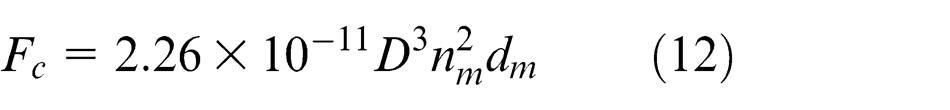
where
From Figure 6, considering the equilibrium of forces in the horizontal and vertical directions
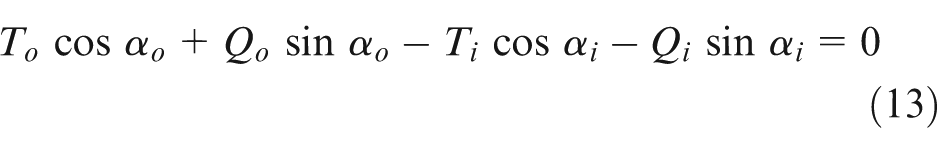
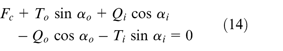
where
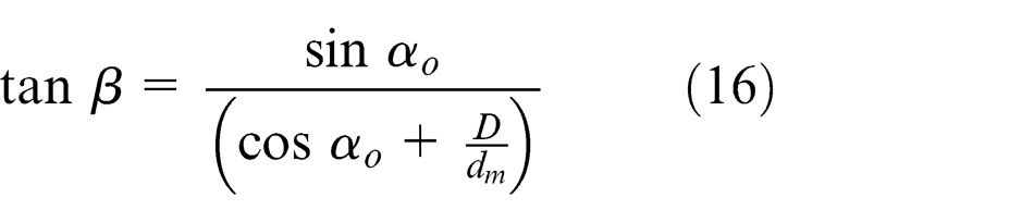
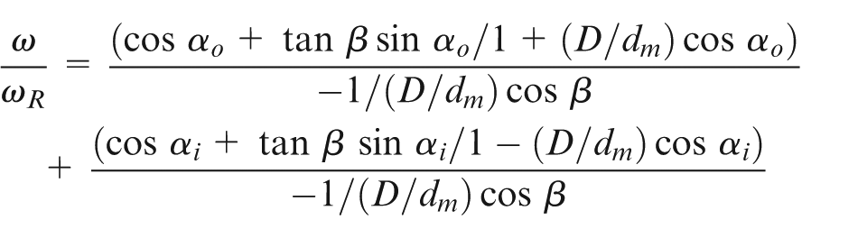
Gyroscopic moment at each ball location is defined as follows (Harris 26 )
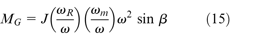
where
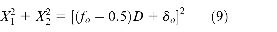
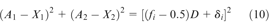
To determine the values for
where
Having computed values for X
1, X
2, αi
, and αo
at any position and given
Analysis of optimum preload
The service life of ball bearings is directly related to the life of the entire machine employing them. The bearing’s performance is strongly affected by lubrication, material, and contamination condition. Bearing fatigue is estimated according to the reliability factor and the axial applied preload. Determining the proper preload represents the ability to ensure superior performance and increase the service life of the bearings. Therefore, it is important to ensure that the operating conditions are well known. In this section, we determine the minimum and maximum acceptable bearing preloads relative to the rotation speed.
Maximum acceptable bearing preloads
In section ‘Analysis of bearing axial preload’, the preload was determined as the main factor that affects service life and internal load distribution of the ball bearings. In equations (2) and (3), the safe service life
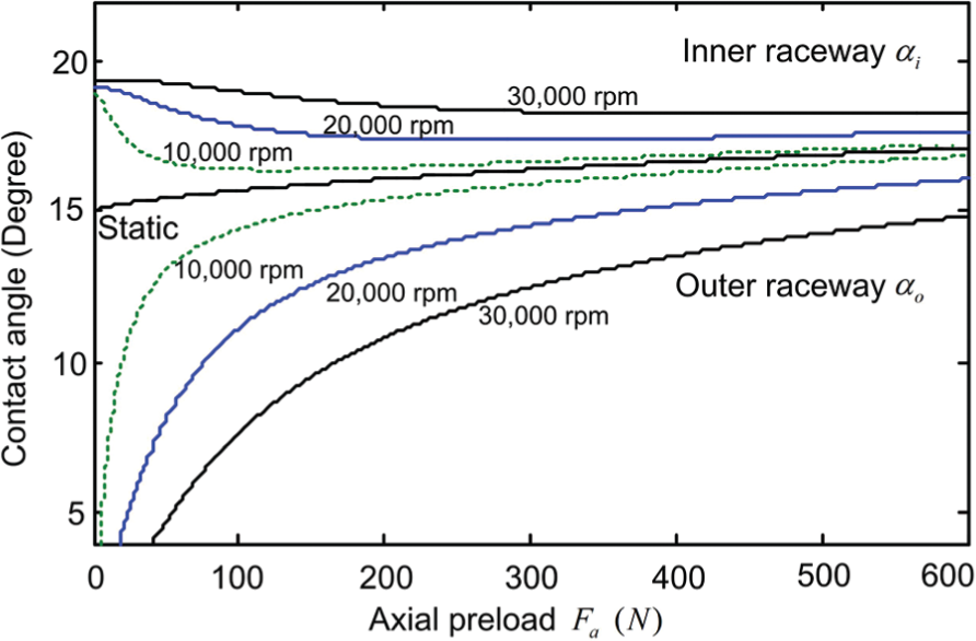
Contact angle versus axial preload for B7007C ball bearings.
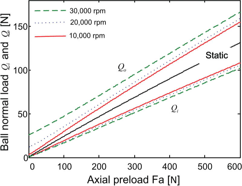
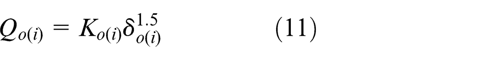
Ball normal load
To obtain a stable service life,
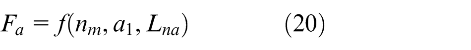
where
Minimum acceptable bearing preloads
The minimum acceptable bearing preloads should restrain balls from contacting the raceway under the effects of gyroscopic moments because sliding may cause bearing wear and excessive heating. Sliding can occur perpendicular to the direction of ball rolling.
27
According to this criterion, the frictional torque produced on the bearing raceways should exceed the gyroscopic moment,

where the coefficient of sliding friction,
Calculation of ball bearing preload
Ball bearings
To verify the validity of the analytical method presented in sections ‘Analysis of bearing axial preload’ and ‘Analysis of optimum preload’, a B7007C ball bearing was selected, with
In section ‘Analysis of optimum preload’, the maximum and minimum acceptable bearing preloads were determined to be a function of the contact angles,
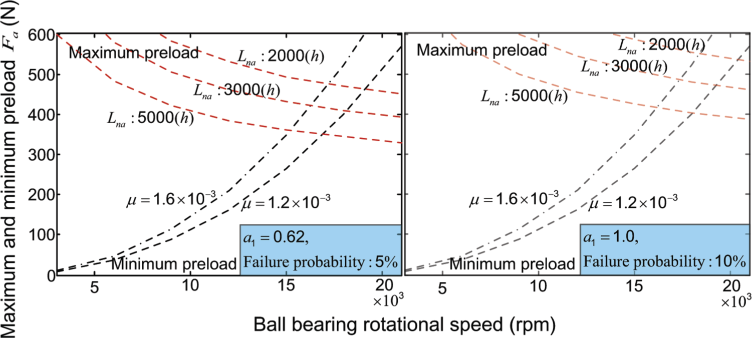
Maximum and minimum acceptable bearing preloads.
Variable optimum ball bearing preload
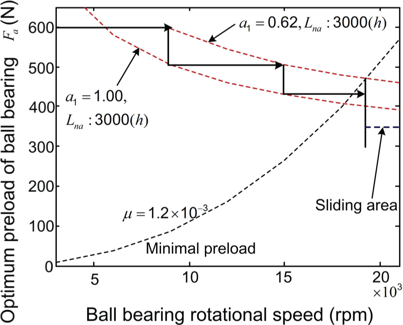
Figure 10 shows a method for determining the optimum preload according to the rotational speed. To obtain the optimum preload curve for the ball bearings, the analysis method described in section ‘Analysis of bearing axial preload’ is applied to determine this preload under the constant service life condition. The optimum preload curve may shift downwards as the reliability life factor,
Optimum preload for the ball bearing related to rotational speed.
In the experiments performed in this study, B7007C ball bearings were used. The bearing parameters were
Experiments and comparisons
Ball bearing temperature increase
Under certain lubrication conditions, the ball bearing temperature is affected principally by axial preload and rotation speed. In this study, the temperature of ball bearings under variable axial preloads and different rotational speeds was detected by a thermocouple (Pt100). The bearing temperature corresponding to the variable axial preloads and different rotational speeds is shown in Figure 11. The bearing temperature increased with an increase in the rotational speed from 5000 to 18,000 r/min. At certain rotational speeds in the low- and medium-speed ranges, the bearing temperature may be reduced, depending on different axial preloads. In the high-speed range, the bearing temperature increased almost linearly with an increase in axial preload.
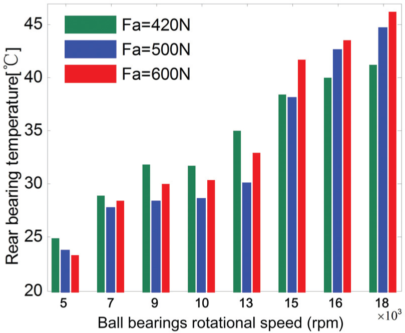
Bearing thermal performance at different speeds.
The vibration of ball bearings
Alfares and Elsharkawy 5 studied the effects of axial preloading of angular contact ball bearings on the vibration behaviour of a grinding machine spindle. The axial preload applied on the bearings played a significant role in reducing the vibration levels of the grinding machine spindle system. In this study, experimental methods were used to examine the relationship among the axial preload, rotational speed, and vibration for ball bearings. Figure 12 shows the experimental results.
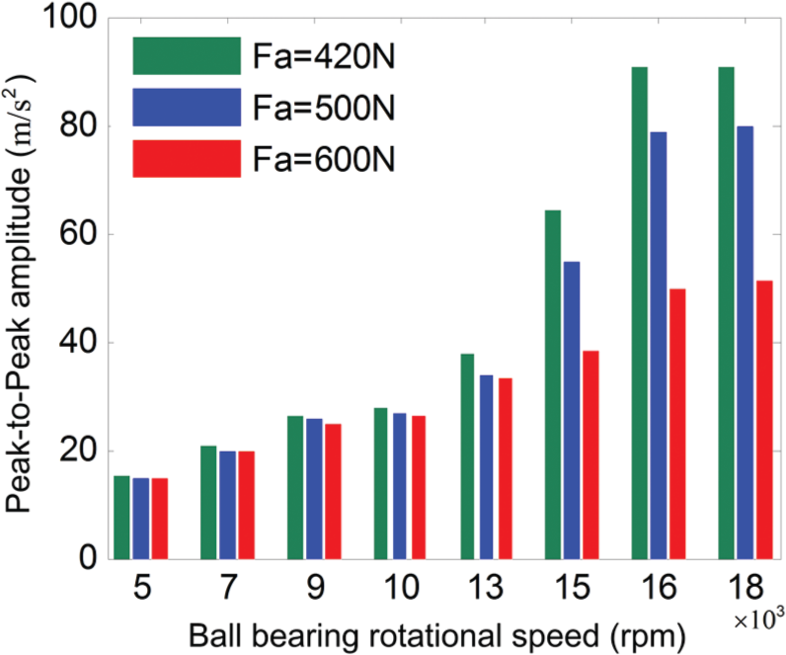
Effect of axial preload on vibration as a function of rotation speed.
For a constant axial preload, the peak-to-peak vibration amplitude increased with an increase in the rotational speed. The peak-to-peak vibration amplitude increased by 494%, 443%, and 252% when the rotational speed increased from 5000 to 18,000 r/min at axial preloads of 420, 500, and 600 N, respectively. At constant rotational speed, the peak-to-peak vibration amplitude decreased with an increase in the axial preload.
Comparison of experimental results
Based on the analysis presented in this study, the optimum axial preload for the entire speed range was obtained as shown in Figure 10, and the axial preload, spindle current, temperature, vibration, and ball bearing rotational speed were determined using the optimum axial preload and contrast preload methods.
The comparison of bearing performance under different speed region is shown in Figure 13. The entire speed range is divided into a low-speed region, a medium-speed region, and a high-speed region, according to the fifth part of this analysis. According to the optimum axial preload method, a low axial preload of 420 N was applied to the ball bearings in the high-speed region and the maximum design axial preload of 600 N was used on the ball bearings in the low-speed region. A medium preload of 500 N was used in the medium-speed region.
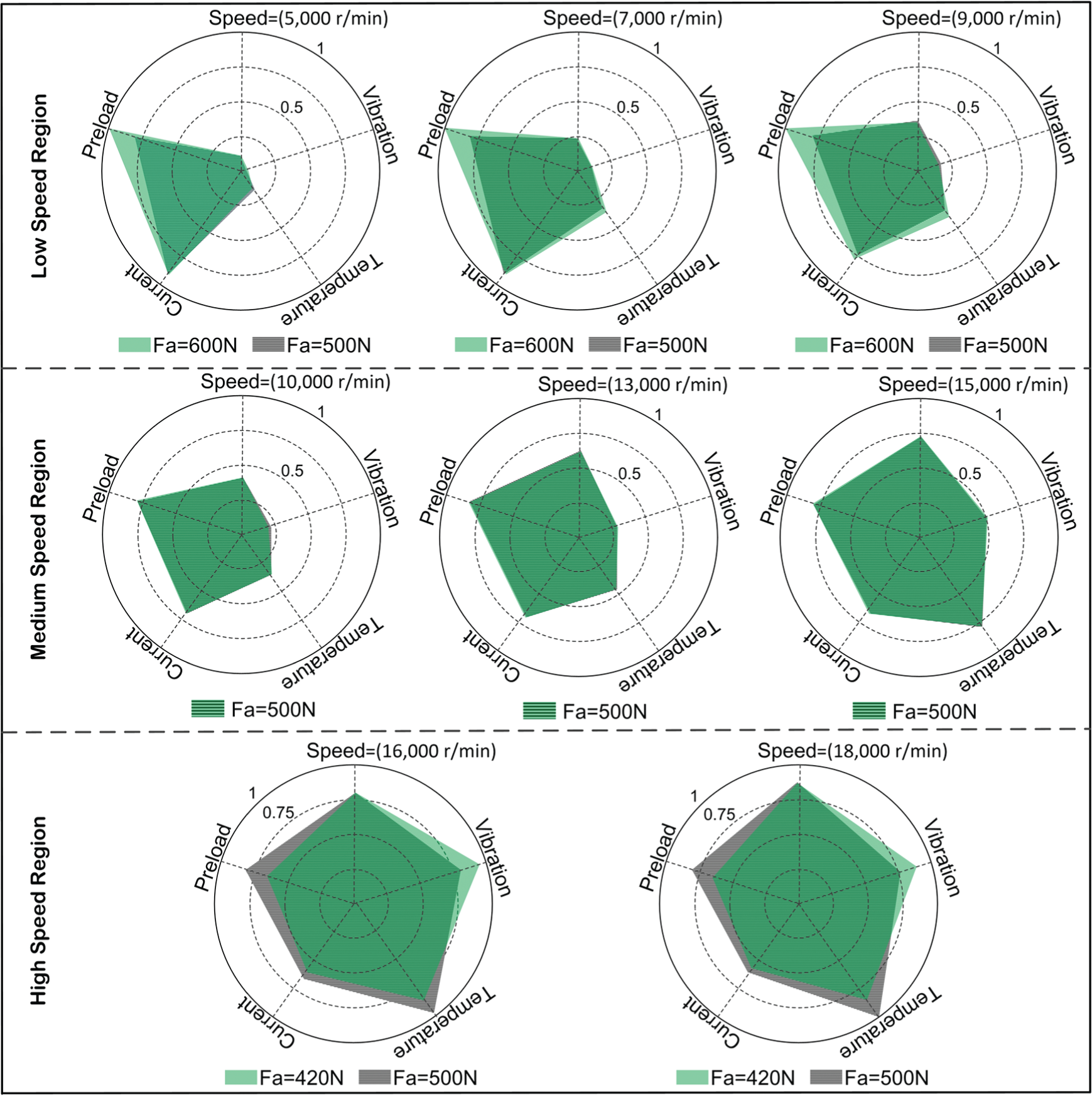
The comparison of bearing performance under different speed region (Low, Medium and High).
In the low-speed region (under 9000 r/min), the high axial preload may have caused the ball bearings to experience high stiffness. The temperature and vibration did not clearly change with an increase in the rotational speed. In the medium-speed region (9000 to 15,000 r/min), the temperature and vibration of the ball bearings clearly increased with an increase in the rotational speed. The change in the spindle current (frictional torque) was not pronounced. Finally, in the high-speed region (15,000 to 18,000 r/min), the temperature and vibration of the ball bearings strongly increased with an increase in the rotational speed.
Conclusion
This article suggests a method for determining an optimum preload on ball bearings. For constant bearing fatigue, the theoretical preload curves could be determined using the fatigue life model by changing the reliability factor. As the speed increases, the optimum preload was hierarchically obtained within the internal region between theoretical preload curves. This method divided the entire speed range into low, medium, and high regions, with a different optimum preload possible in each region. The following conclusions were drawn:
The vibration and temperature of the ball bearings increased, and the motor current decreased with an increase in speed. In the low-speed range, the motor current was used to determine the preload within the temperature and vibration limits of the ball bearings. In the medium-speed range, the vibration was used to determine the axial preload within the limits of the temperature and motor current of the ball bearings. In the high-speed range, the temperature was used to determine the preload within the limits of the vibration and motor current of the ball bearings.
To improve the reliability bearing fatigue life, in the low-speed range, the maximum design preload (design value) was set as the initial preload. With an increase in speed, the optimum preload was hierarchically obtained within the internal region between theoretical preload curves.
The experimental results indicated that temperature and vibration increased and the motor current decreased with an increase in speed. The axial preload more strongly affected the performance of the ball bearings in the high-speed range than others. Furthermore, the effects of speed on the bearing temperature, motor current, and vibration are stronger than preload.
Unlike the constant preload method, the method presented in this study maintained the constant theoretical service life and allowed ball bearings to provide a suitable rotation rate for different machining processes with a single machine tool spindle.
Footnotes
Appendix 1
Declaration of Conflicting Interests
The author(s) declared no potential conflicts of interest with respect to the research, authorship, and/or publication of this article.
Funding
The author(s) disclosed receipt of the following financial support for the research, authorship, and/or publication of this article: This work was financially supported by the National High Technology Research and Development Program of China (no. 2015AA043004).