
Abstract
Light weight, compactness and efficiency are key objectives in high performance vehicular transmission systems, which are subject to large variations in torque and power. Pitch line velocities of up to 52 m/s and teeth pair contact pressures of up to 3 GPa are routinely encountered under race conditions. Contact patch asymmetry due to angular misalignments between input and output shafts leads to the generation of high edge stress discontinuities on gear flanks, inducing fatigue spalling which affects system durability. Crowning is widely used as a palliative measure to mitigate these undesired effects. These problems can be further exacerbated by contact footprint truncation. The paper presents a new approach to modelling the kinematics and contact micro-geometry of meshing conjunctions of involute spur gears with profile and lead modifications. A time-efficient analytical method is presented to accurately determine the contact footprint and kinematics, leading to the solution of highly loaded non-Newtonian mixed thermo-elastohydrodynamic contact under the extreme prevalent conditions of high performance vehicular transmissions. The effect of tooth form modification on contact footprint truncation, contact kinematics and generated frictional power loss is investigated. This approach has not hitherto been reported in literature.
Keywords
Introduction
The modern lightweight and compact powertrain concept provides significant advantages in fuel efficiency but can lead to a plethora of noise and vibration concerns. Weight reduction of rotational components in the driveline, in particular, tends to improve throttle response and errant rigid body dynamics. However, this is often achieved at the expense of vibration and noise due to low structural damping, for example from hollow driveshaft tubes. 1 In transmissions, the supporting gear shafts can be made hollow in line with the lightweight concept. This is particularly true of transmissions of high performance vehicles. Shaft-integrated lubricant galleries can also be present to lubricate the bearing supports and gear contact conjunctions but require the removal of additional material which further adds to the reduction in component rigidity. This can lead to increased structural vibration (elastodynamics). Short and stubby gear shafts and appropriate material selection mitigate the elastodynamic behaviour to a large extent. Contact loads in gear teeth meshing conjunctions in high performance vehicles can routinely exceed 20 kN. In practice, the combined torsional deflection and bending of the supporting gear shafts can cause relative angular displacement, resulting in assymetric edge loading of teeth pair contacts. With particularly compact gears, such as in the transmissions of high performance vehicles, truncation of the contact footprint of meshing gear teeth causes high localised pressures at the loaded flank edges, which can lead to scuffing and/or fatigue spalling with appearance of pits. Inspection of run-in gears has shown skewed scuffing and pitting of flank surfaces at their edges due to the presence of edge stress discontinuities, similar to those reported for misaligned rolling element bearings.2–4 To mitigate this phenomenon teeth crowning is used as a palliative measure in the same manner as axial edge relieving of rolling element bearings highlighted in Johns and Gohar. 2
Several authors have investigated improvements in the meshing contact of misaligned spur gears through crowning.5–7 However, they have primarily focused on mitigating the effects of misalignment without regard to contact patch truncation and its effect on generated frictional losses. Harianto and Houser 8 assessed the effect of crowning and its influence upon generated contact stress distribution within an active area of the contact face width. Variations in peak-to-peak transmission error were also presented by varying the extent of crowning and misalignment in order to assess their implications for gear dynamics. A similar analysis was conducted by Seol and Kim, 9 where the effect of crowning on dynamic transmission error and the dynamic loading factor were ascertained. While truncation was observed in the results presented by Mao, 6 no further assessment seems to have been conducted to establish whether the occurrence of truncation is a hindrance to transmission efficiency.
This paper provides predictions of friction in the contact of meshing teeth pairs. Contact friction occurs as the result of shear of a thin film of lubricant as well as any direct contact of rough surfaces of mating gear teeth pairs. The thin lubricant films in the highly loaded contact of teeth pairs at high loads, representative of conditions investigated in this paper, are subjected to non-Newtonian shear as highlighted in the literature.10–13 In practice, the real mating surfaces are rough. Therefore, direct interaction of mating surface topography through the thin lubricant film also contributes to the generated friction. The paper presents the effect of teeth crowning upon generated friction and power loss of meshing gears under combined non-Newtonian thermal shear of thin lubricant films as well as direct interaction of real rough surface topography, an approach not hitherto reported in literature.
Method of analysis
Lubricated contacts
Loaded gear teeth routinely experience contact pressures of the order of 1–3 GPa. The meshing conjunction operates under elastohydrodynamic (EHD) regime of lubrication with Newtonian or non-Newtonian shear of a thin lubricant film, depending on the prevailing contact conditions, contact kinematics and load.10–13 The generated contact friction comprises of viscous shear of the lubricant film and any direct interaction of contiguous surfaces. For an analytical solution, such as in Karagiannis et al.,
10
estimation of lubricant film thickness is important. This is made through use of lubricant film thickness equations such as that originally provided by Grubin.
14
Subsequently, many authors have provided similar expressions through regression of numerical results with different combinations of operating conditions, such as contact speed and load.15–18 A comprehensive list of these earlier equations is provided in Johns-Rahnejat.
19
All these equations were for steady-state conditions and do not include features such as squeeze film effect in mutual approach of surfaces or changes in the lubricant entrainment angle into the contact as the result of rolling and sliding. For the former, Jalali-Vahid et al.
20
provided an equation, verified by optical interferometric studies, and Rahnejat
21
provided a squeeze film term as an addition to that of Mostofi and Gohar
22
for generalised elliptical point contact with angled entrainment flow, an approach which was also made by Chittenden et al.
23
Similar expressions exist for finite line contact footprints.
24
The current study assumes an elliptical point contact footprint of large aspect ratio, thus the expression in Chittenden et al.
23
is used

Due to the limitations of computational power, the early solutions assumed low to medium contact loads with fully flooded inlets and isothermal Newtonian conditions. Most gearing contact inlets are starved as some of the inlet flow is subjected to counter and swirl flows. Therefore, zero reverse flow boundary should be determined, beyond which all the entrained lubricant is drawn into the contact as shown by Tipei 25 and experimentally investigated for a circular point contact by Johns-Rahnejat and Gohar 26 and numerically verified by Mohammadpour et al. 27 With swirl and counter flows at the contact inlet, starvation occurs which reduces the lubricant film thickness in the contact (reduced supply), thus affecting friction and power loss. 28 This approach assumes a fully flooded inlet, which is the basis of equation (1) and film thickness is assumed not to vary along the semi-major axis which significantly reduces the computation times.
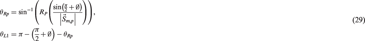
Tooth contact analysis (TCA)
Lubricant film thickness formulae such as equation (1) require prior knowledge of the instantaneous contact curvatures of mating teeth and their tangential sliding velocities. These are used to determine the speeds of lubricant entrainment into the contact. For ideal involute spur gears, these parameters are functions of basic formulae derived from the principles of involute geometry, as shown in Townsend
29
and Litvin et al.
30
However, these approaches do not take into account gear teeth modifications which are common practice by manufacturers to improve upon the baseline involute for operational integrity and durability. In cases where modifications such as profile shift (addendum modification), tip relief or crowning is applied to gear teeth, formulations such as those found in Townsend
29
and Litvin et al.
30
become inappropriate. In this paper, a methodology is developed to accurately estimate the instantaneous local surface velocities and contact curvatures for modified involute spur gears. The method is based on tracking the meshing conjunction along the length of contact (LOC) as illustrated in Figure 1.
Length of contact (LOC) of a spur gear pair.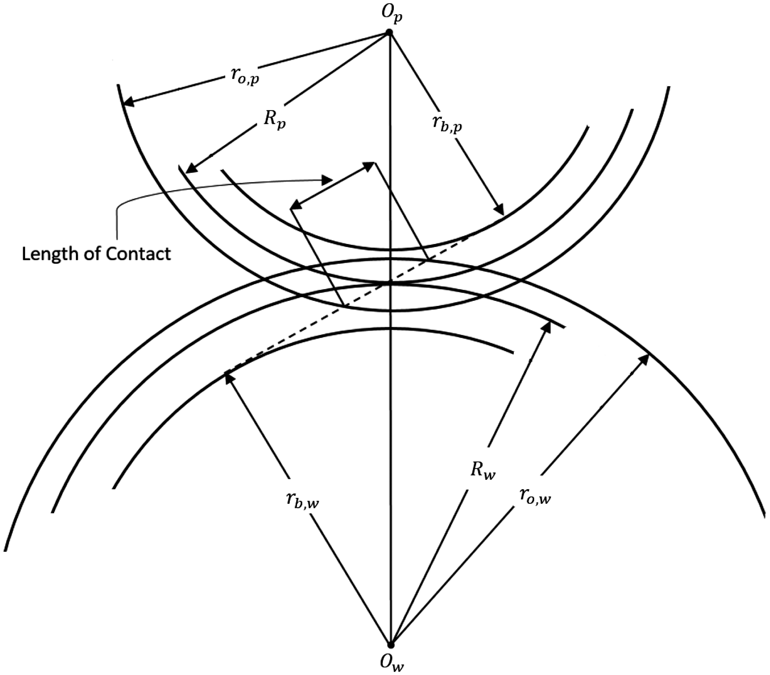
The ideal involute gear tooth profile is first rendered for a finite number of nodes with respect to the Cartesian X–Y frame of reference for a specified base radius rb, and outer radius ro, where the origin of the coordinate set is at the gear centre (Figure 2).
Generating an involute tooth profile.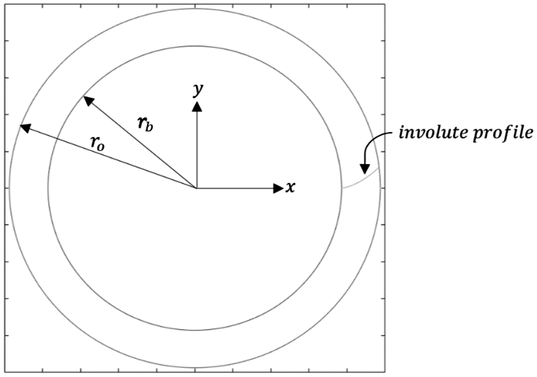
Coordinates are generated for both the driving pinion gear and the driven gear wheel, for an involute roll angle in the range:


When the gears have applied profile shifts, the coordinates of the shifted profile become


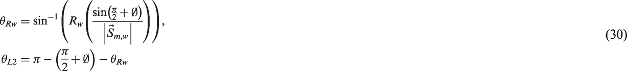
It should be noted that profile shifts alter the working pitch radii of the meshing gears, which is of consequence for the accuracy of contact tracking. The effective working pitch radii of profile-shifted pinion and wheel, RP and Rw are obtained as


If the sum of profile shifts applied to a meshing gear pair does not diminish, then the operating centre distance, ac and consequently the working pressure angle ∅ of the gear pair alter and can be calculated as


For any subsequent tooth modifications,
For gears with a parabolic tip relief, the magnitude of transformation at each discrete node along the profile is determined by expressing the relief function in vertex form as a function of the involute roll angle and the magnitude of the local relief, l as


Transformation of magnitude l is applied to


The resulting profile coordinates after tip relief are obtained as


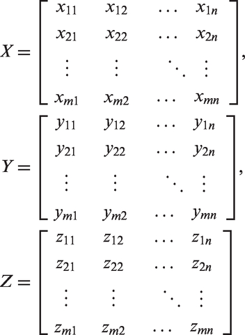
Gear tooth profile modifications such as profile shift and tip relief are applied prior to any lead modification. As a single cross-section of a spur gear along the X–Y plane is representative of the gear without any lead modification in three dimensions, the profile coordinates can be replicated for the entire width of the tooth flank t, along the z-direction (into the plane of paper in Figure 2). This renders the active flank in three dimensions. The selected number of lead nodes n should correlate positively with the required sensitivity for variations in micro-geometry along the lead direction of the flank. The system of coordinates for the resulting generated flank is represented as three coordinate matrices of dimensions

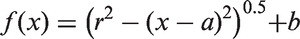
The crowning modifications assessed in the current study are circular. However, the presented methodology can be readily extended to more complex forms such as parabolic and asymmetric crowning. At the edges of the tooth flank, the magnitude of crowing transformation v is taken to equate to the prescribed crowning amount Cb, while at the centre of the tooth flank v is assumed to diminish
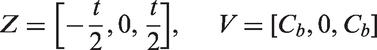
The crowning magnitude v can be determined for each nodal position along the flank by expressing v, analogous to the amount of material removed from the ideal involute flank, as a circular function of the nodal position along the z-axis, thus

The three unknown coefficients, a, b and r can be obtained simultaneously with the knowledge of the three coordinates provided above by Z and V. Crowning magnitude can then be expressed in the form


The coordinates on the flank post-crowning are then calculated as


It should be noted that the application of crowning alters the curvature of the flank

The reduced radius of curvature along the major axis of the contact ellipse of a meshing conjunction becomes

The LOC for a given gear pair, shown in Figures 1 and 3, is expressed as
Calculating the length of contact (LOC) of a modified gear pair.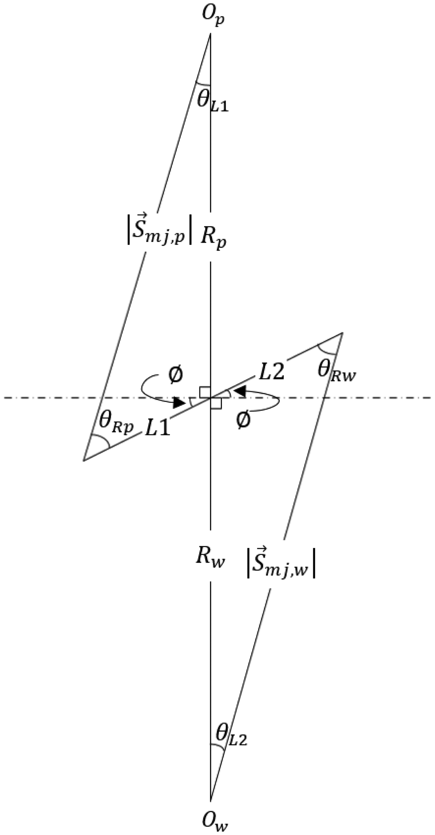

From Figure 3, 

It transpires that any positional estimations of meshing conjunctions along the LOC are only accurate for a given cross-sectional profile. While this is inconsequential for gears without lead modifications, in the case of symmetrically crowned gears, it is logical to use the X–Y cross-section where
For a given contact ratio mp, simultaneous contact of teeth in and out of mesh can be modelled as a set of fundamental functions, the magnitudes of which correspond to the position of the contact conjunction, Xi on the LOC relative to the pitch point (Figure 4).
Contact tracking.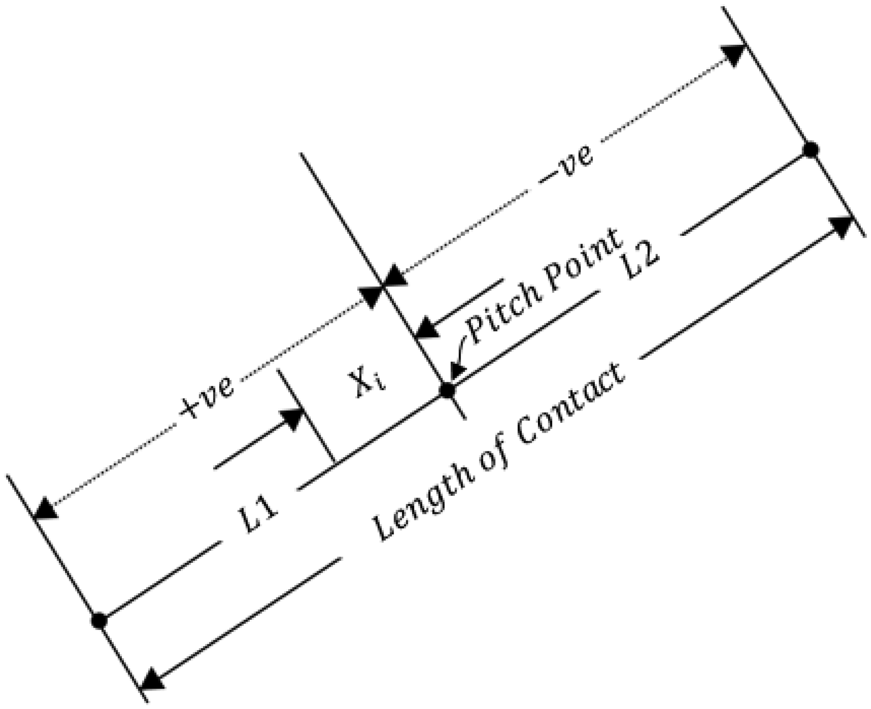
The number of fundamental functions necessary to fully define the contact between a gear pair is determined by the maximum number of simultaneous meshing contacts which can exist for a given gear pair. The leading and trailing teeth pair contacts are separated by a length along the LOC, equalling the base pitch pb. In the contact tracking algorithm presented here, this length is expressed as an equivalent rotation angle

Consequently, each fundamental signal has a period

Thus, for a gear pair where A snapshot of meshing pattern for a gear pair of 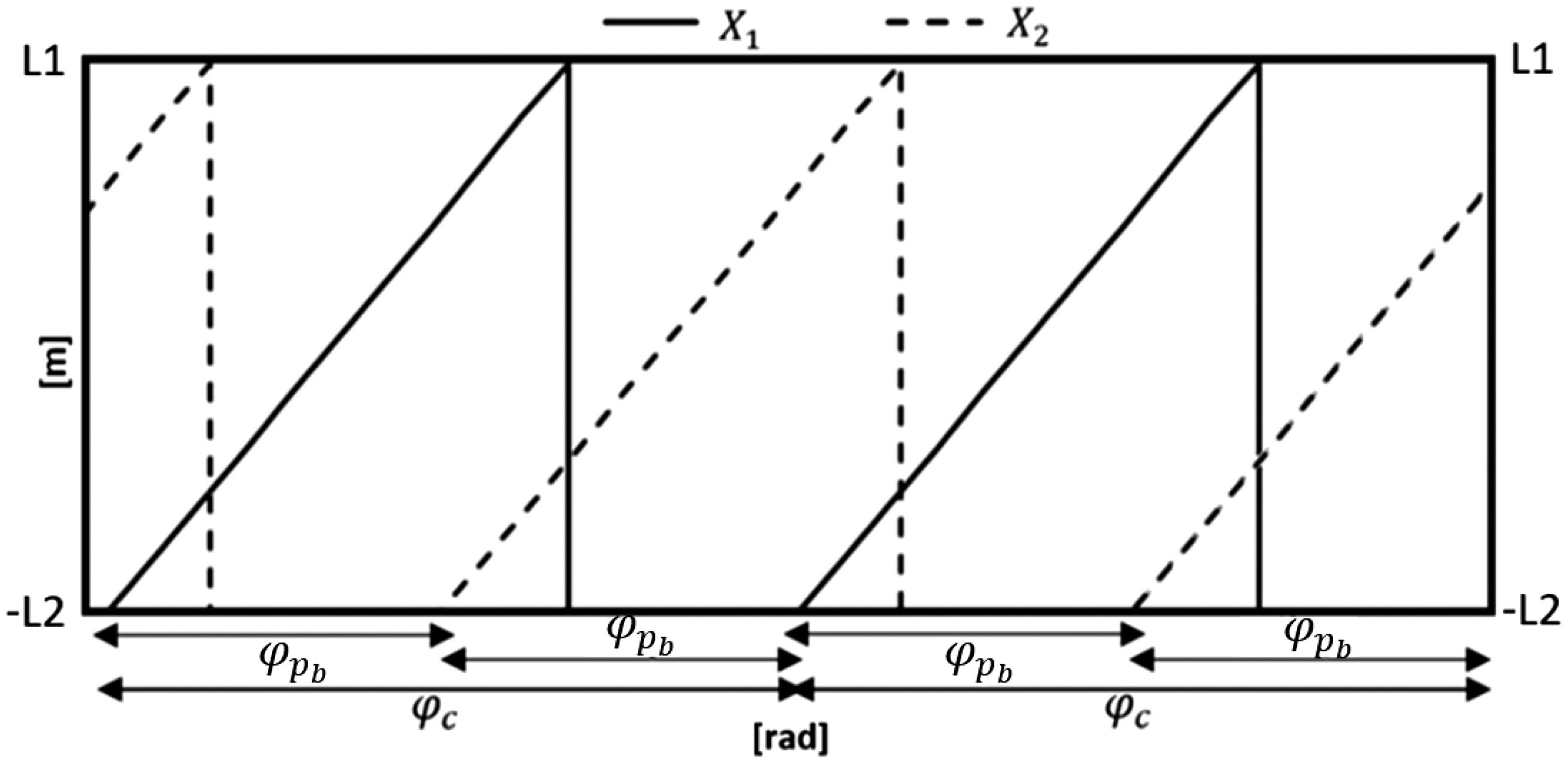
The progress of the gear pair along this recurring contact cycle is expressed as

The instantaneous contact location X1 can then be calculated as

Depending on if X2 is trailing or leading X1 at a given instant, it can be obtained as

While Xi lies on the LOC:


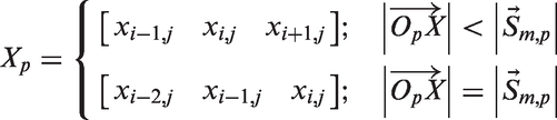
As the pinion and wheel profile coordinates have been previously expressed as functions of


However, equations (39) and (40) do not hold true along the width of the flank for a given pinion angle

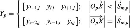
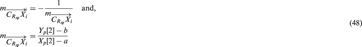
By subsequently determining the nodal coordinates on either sides along the profile of the instantaneous meshing conjunction position Xi, the instantaneous curvature along the minor axis Rx of the elliptical contact footprint can be determined at each nodal coordinate for the width of each tooth. This also serves to calculate the velocity component tangential to this curvature (i.e. the local surface velocity). Thus, for a specified contact location along the pinion tooth width, instantaneous coordinate sets Xp, Yp and Zp are given as

As in equation (18), the centre

The instantaneous surface velocities of the pinion and wheel teeth in mesh can be resolved along the contact tangential plane (i.e. along the minor axis of the contact ellipse) as


And for the pinion


Replicating equations (46) to (49) for the wheel yields its corresponding instantaneous local surface velocities. Note that assuming no side-leakage flow of the lubricant across the teeth flanks, the components of the pinion and gear surface velocities along the major axis of the contact ellipse become
This assumption is reasonable due to the thinness of the prevailing lubricant film. Therefore, the lubricant entraining velocity along the minor axis of the contact footprint used in equation (1) at any instant of time during meshing of a gear teeth pair is obtained as

Similarly, the tangential components are used to obtain the instantaneous contact sliding velocity as

As this methodology is sensitive to variations in contact geometry along the flank, variations in contact kinematics and curvatures at the discrete nodes along the major axis of the prevailing contact patch are considered.
Through subsequent application of a quasi-static finite element technique, the TCA software (CALYX, Advanced Numerical Solutions) employed in this study allows for accurate representation of instantaneous load distribution across the flank of the modified spur gear teeth. 30
The contact load applied per teeth pair is a function of the dynamic response of the system. The ratio of the applied load Wi on a given flank under consideration to the total transmitted load WT10,11 is known as the load factor,

Time-varying contact stiffness resulting from the variation in the meshing contact location and simultaneous load sharing between multiple teeth pairs is taken into account through TCA to acquire representative individual tooth loading distributions.
To observe the crowning-induced variations in the localised contact pressures along the semi-major axis of the elliptical footprint, the instantaneous contact ellipse is discretised into a number of finite equivalent rectangular strips (similar to the contact of slender cylindrical rollers). The semi-major and semi-minor half-widths of the prevailing contact ellipse, a and b can be calculated as
18


The resulting contact ellipse is discretised into n individual rectangular contact strips, where the semi-major and semi-minor half-widths of each strip aj and bj are


The distance of the centre point of a strip j from the centre point of the contact ellipse along the semi-major axis is

For instances, where the contact ellipse is truncated at the gear teeth flank edges, the total length of the contact semi-major axis is limited to the length of the gear flank t. The semi-major axis of each individual discretised strip then becomes


The local load acting over each discretised strip Wj is estimated using knowledge of the load intensity distribution Instantaneous flank load intensity distribution – TCA.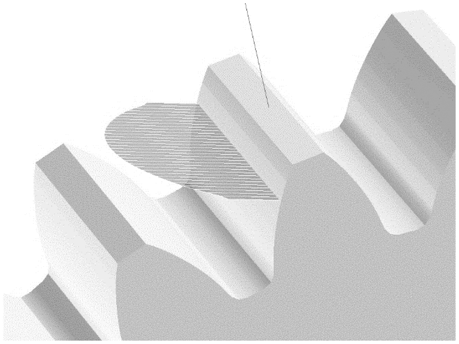


Viscous friction
The conditions investigated in the current analysis pertain to transmissions of high performance vehicles at high contact loads and shear rates, leading to thin non-Newtonian thermo-elastohydrodynamic (TEHD) films. Evans and Johnson
31
modified Crook’s
32
original thermal analysis of Newtonian fluids to account for discrepancies between theoretical and observed values of viscous traction in EHD contacts. They provided an analytical expression for coefficient of friction under TEHD conditions subject to non-Newtonian shear of a thin film, which is utilised in this analysis
31

Note that the coefficient of friction is calculated for each discretised strip of the instantaneous contact. Therefore, an average of these can represent the value at any instant of time during the meshing cycle.

The generated friction due to viscous shear of the lubricant film is then expressed as

Flash surface contact temperature
Crook
32
showed that heat generated due to viscous friction is transferred across the film through conduction to the solid surfaces, which in turn rapidly convects away. Through the reasonable assumption that the shear stress τ varies parabolically along the direction of lubricant entrainment, Crook showed that the temperature rise of the solid surfaces in EHD conjunctions, from bulk temperature


With the assumption that heat generation occurs locally at the centre plane of the lubricant film and that the separated solid surfaces have the same temperature, Johnson and Greenwood
33
derived formulae, estimating the temperature rise across the lubricant film. The resulting estimate is the local temperature rise, averaged across the semi-minor axis of the elliptical contact footprint at any given instant. With the assumption that the lubricant thermal conductivity remains constant, whilst its dynamic viscosity reduces exponentially with any rise in temperature and the lubricant’s temperature–viscosity coefficient β, they were able to accurately predict the prevailing lubricant film centre-plane temperature as


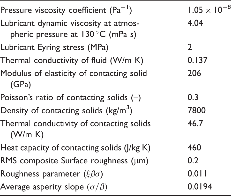
Lubricant rheology and surface data.
Boundary friction
The thin lubricant films in the meshing contacts of loaded gear teeth pairs in high performance transmissions are comparable in magnitude to the roughness of the teeth flanks. Consequently, asperity interactions and therefore boundary friction is to be expected. Figure 7 is an image of a patch of a tooth flank obtained through use of white light interferometry with a vertical resolution (in the z-direction) of 10 nm and 0.175 µm in the contacting xy plane. The gear considered has been subjected to severe race conditions for a distance of 4000 km, well past its running-in state.
Surface roughness of gear tooth flank centre after 4000 km on a high performance racing drive cycle.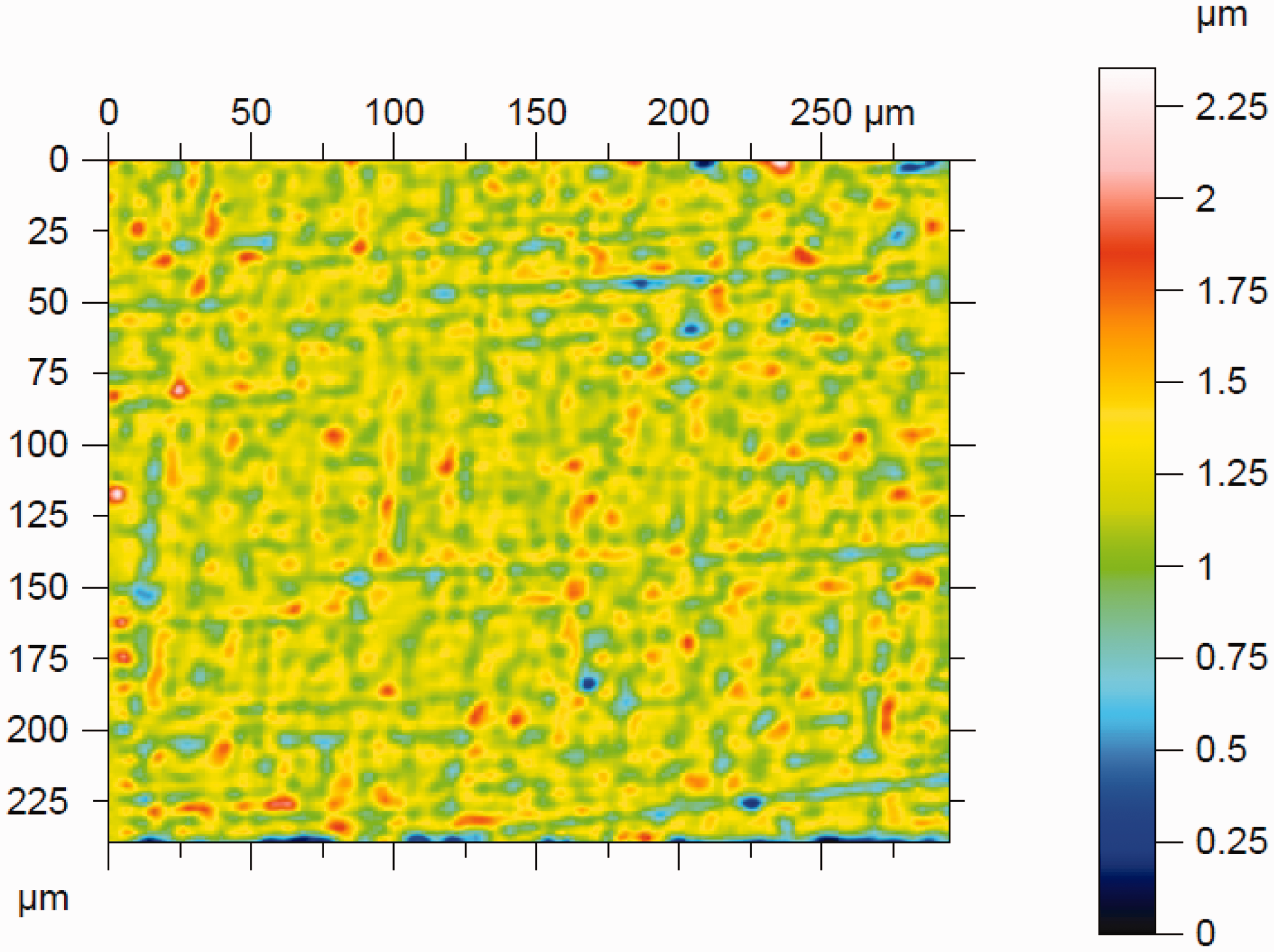
Greenwood and Tripp
34
developed a method to evaluate the generated boundary friction as the result of direct interaction of asperities on the counter face contacting surfaces. The method assumes a Gaussian distribution of surface height asperities. When mixed or boundary regimes of lubrication occur, Stribeck’s oil film parameter: 

The roughness parameter
Asperity friction should be considered in mixed and boundary regimes of lubrication. A thin adsorbed film (a tribo-film) exists at the summit of the asperities and/or is entrapped in their interspatial valleys. This thin tribo-film is subjected to non-Newtonian shear, thus boundary friction 


In this study, the topographical properties of the contacting teeth surfaces (i.e. surface roughness, roughness parameter and average asperity slope) are assumed constant both along and across the flank. However, values used in this study are based on measurements sampled over multiple areas of the flank, thus it is unlikely to significantly affect the results of the analysis.
Power loss
The total instantaneous friction in each discretised element is as the results of combined viscous and boundary friction contributions

The instantaneous power loss per instantaneous contact strip is determined as

Results and discussion
The effect of symmetric crowning (Figure 8) and contact ellipse truncation on contact efficiency in spur gears is studied.
Symmetric gear teeth crowning modification (plan view).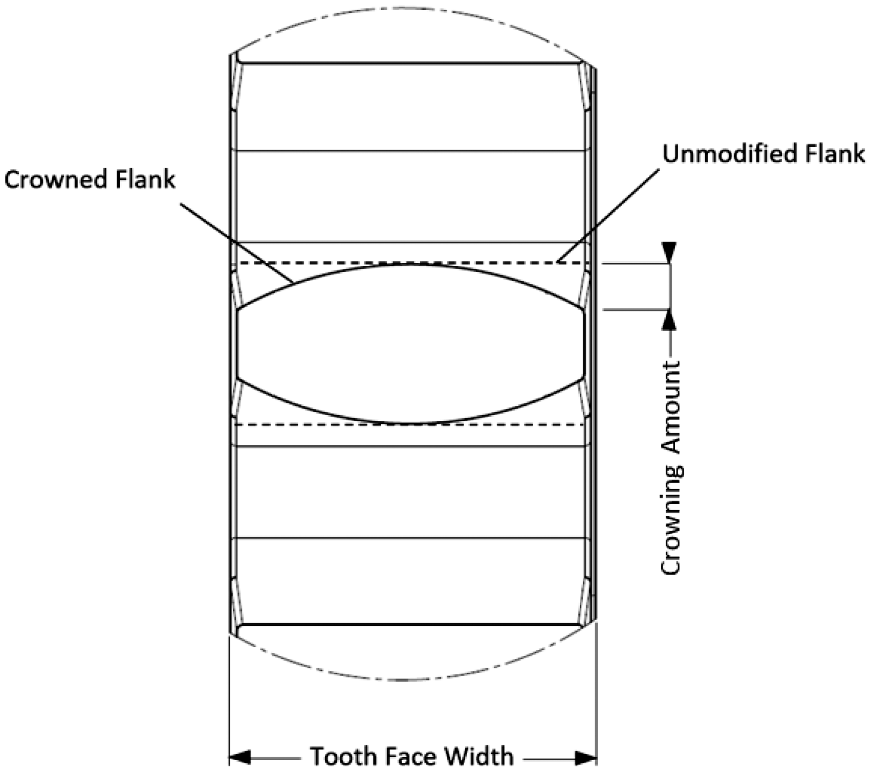
Pinion and gear parameters.
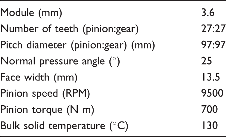
Table 2 lists the relevant data for the solid surfaces and the lubricant rheological properties.
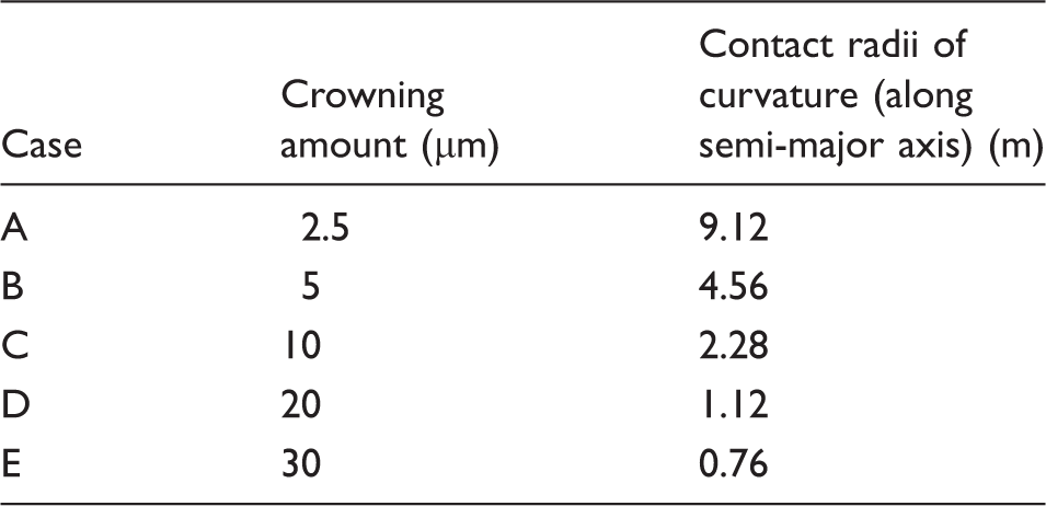
Amount of crowning and semi-major axis curvatures.
A complete meshing cycle is simulated through quasi-static TCA at 150 discrete contacting locations from root to tip of the active flank area for each case listed in Table 3. The prevailing local load intensity, contact curvature, and rolling and sliding velocities are calculated for 251 equally spaced locations (strips) along the contact’s semi-major axis. The resulting 251-by-150 data arrays form the input to the analytical TEHD model. The computation time for each discrete location, i.e. instant of meshing is approximately 2 min.
The size of each discretised cell (strip) in the TEHL model was selected through iterative trial and error, allowing appropriate compromise between computational effort and any loss of necessary resolution to observe the effects of contact ellipse truncation at the edges of contacting flanks. Consequently, the analytical TEHL model discretises the prevailing contact width (along the semi-major axis of the contact footprint) into 128 equally spaced sampling points. Variations in the tribological parameters at each discretised location are acquired for a complete meshing cycle, simulated in 100 discrete contacting locations from root to tip of the active flank area.
For the purposes of estimating the instantaneous film thickness (equation (1)), the contact geometry and kinematics are taken as those at the centre of the instantaneous contact footprint. Figure 9 shows the variation of the central lubricant film thickness, as a pair of meshing teeth contact progresses from the root to the tip.
Central contact lubricant film thickness variation in a meshing cycle.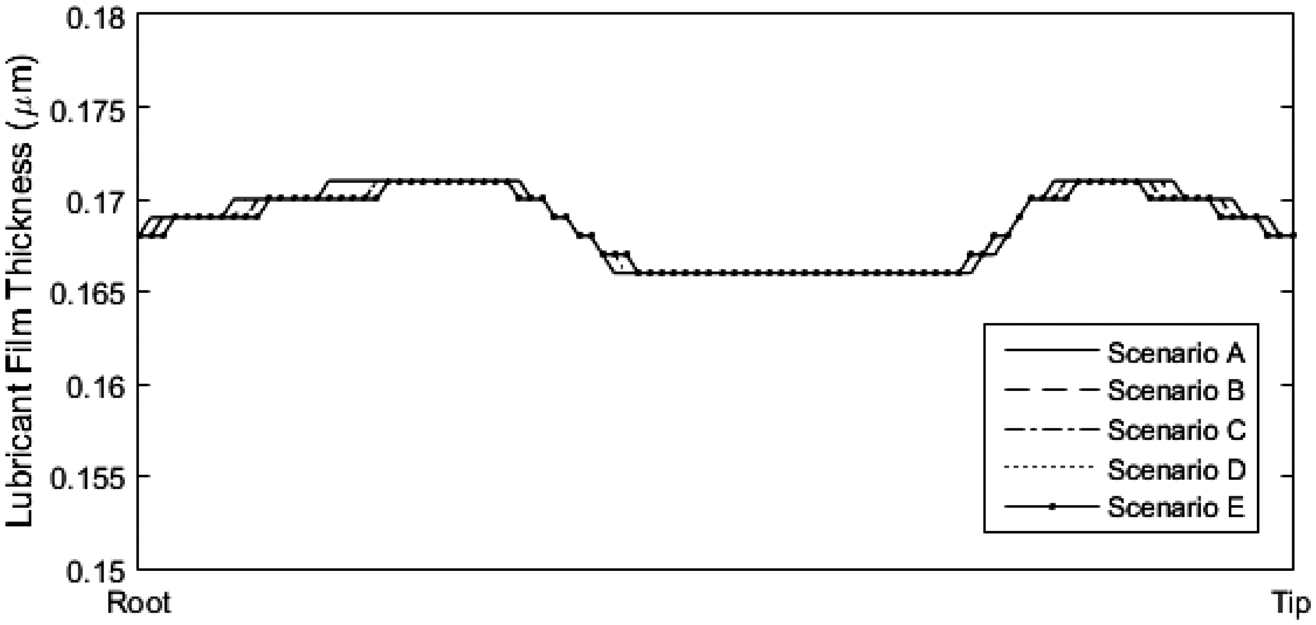
The vertical axes in Figures 10 to 12 and 14 have been normalised to represent the length of the active tooth flank in the direction of the tooth profile. Similarly, the horizontal axis represents the length along the flank width from one edge to the other (i.e. the lead direction).
Variation of contact footprint geometry in a meshing cycle for (a) Case A, (b) Case B, (c) Case C and (d) Case D.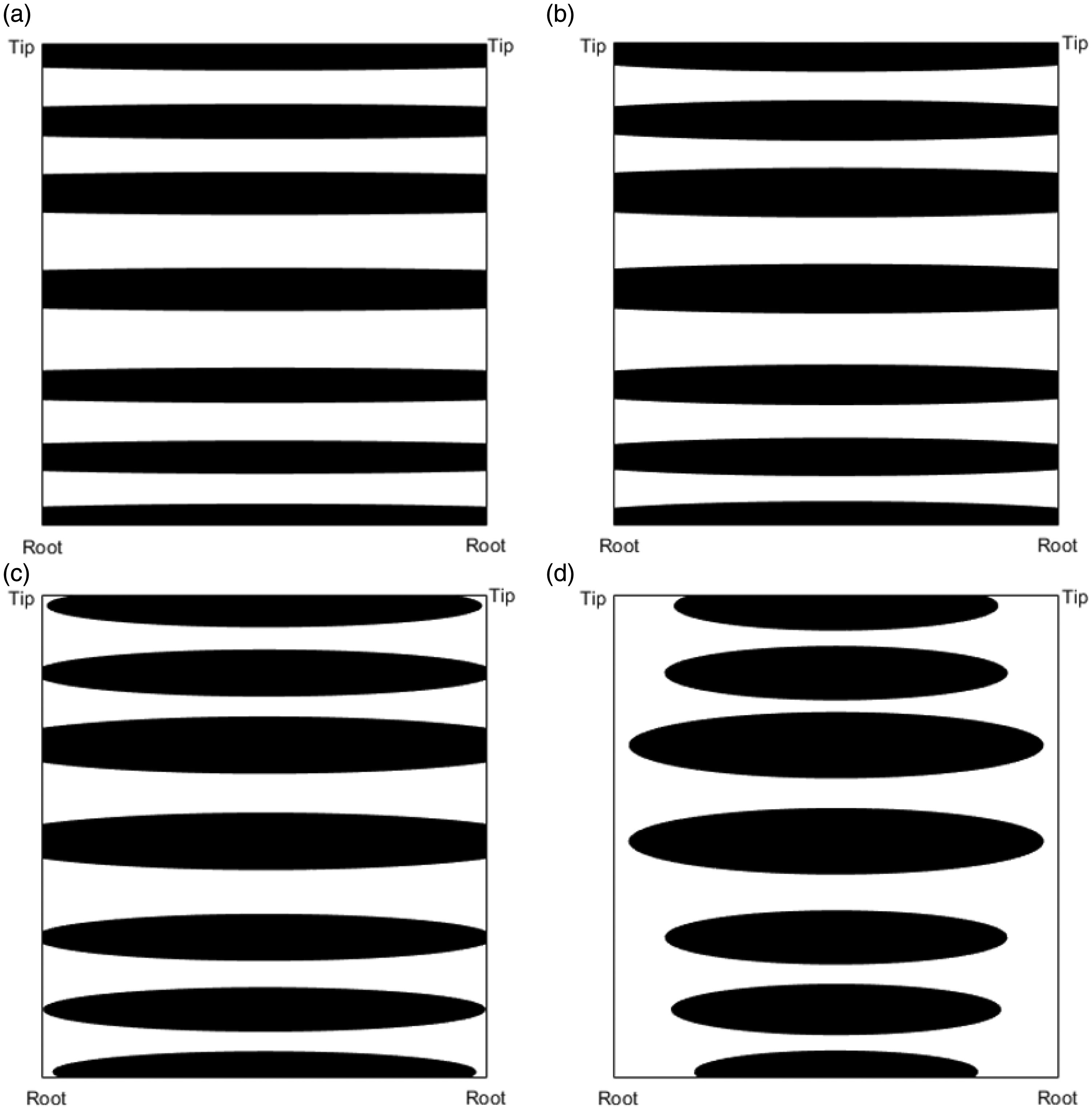
Hereinafter, figure suffixes correspond to the scenario studied. Figure 10(a) to (d) shows the variation of contact footprint geometry at seven discrete locations on the active flank, as a single teeth meshing contact progresses from the tooth root to the tooth tip for scenarios A–D under the loading conditions given in Table 1. Case E is not shown for sake of rationalised presentation but follows the same trends as the others.
With sufficient load or small amount of crowning, any crowning-induced curvature is flattened. If the semi-major width of the resulting contact ellipse is larger than the available tooth width, the contact footprint is truncated along the edges of the gear tooth flank width. This is observed for the total duration of contact from its root to its tip in Figure 10(a) and (b). Figure 10(c) shows that the truncation only occurs when the contact is approximately halfway up the flank. This is because while the contact on the active flank remains in the vicinity of the flank tip and root, leading and trailing teeth are still in contact with their conjugate pairs. Thus, the load is shared between them and the individual tooth loads remain lower, subject of course to the instantaneous load-share ratio: Contact pressure distribution on an active flank (GPa) – complete meshing cycle: (a) Case A, (b) Case B, (c) Case C and (d) Case D. Contact power loss contour (W/mm) for a complete meshing cycle: (a) Case A, (b) Case B, (c) Case C and (d) Case D.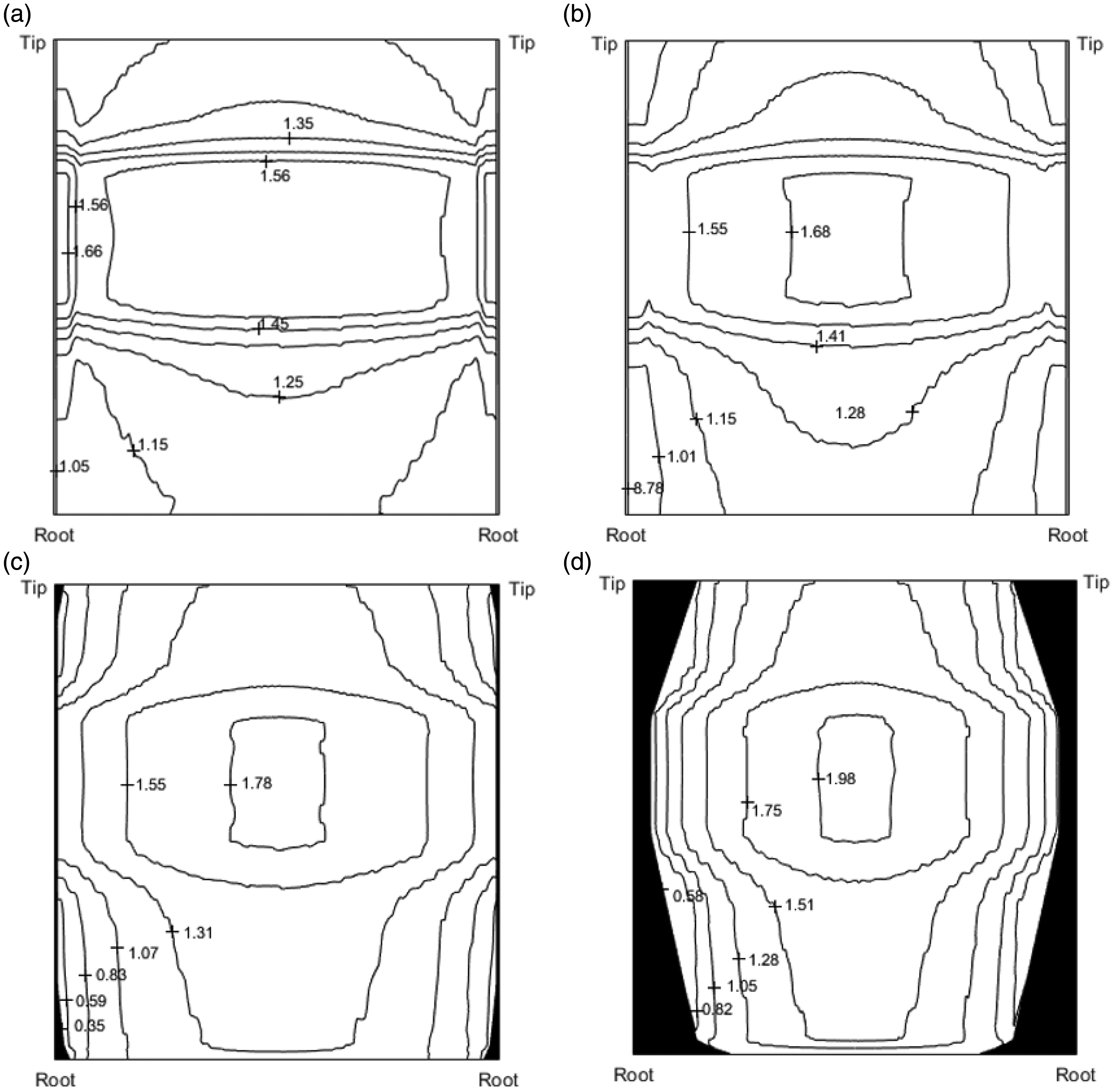
A crowning magnitude of 10 µm (Figure 11(c)) is found to be sufficient to mitigate these pressure concentrations at the contact edges. This is illustrated by the uniform pressure fields on the flank edges in Figure 11(c). However, the redistribution of load on an active tooth flank creates areas of significantly higher pressures towards the flank centre, even though the total active flank area remains largely unchanged (Figure 11(a) to (c)). Regions, where contact does not occur are illustrated in black. This trend of increased pressures at the flank centres is further exaggerated in Figure 11(d), where the extent of crowning is higher and the active contact area is reduced, as would be expected.
The elimination of stress discontinuities reduces the onset of contact fatigue and wear at the edges of flank and lubricant depletion there. These issues are adequately described elsewhere with regard to lubricated contacts.4,19,37 This study focuses on the resulting effects on power losses.
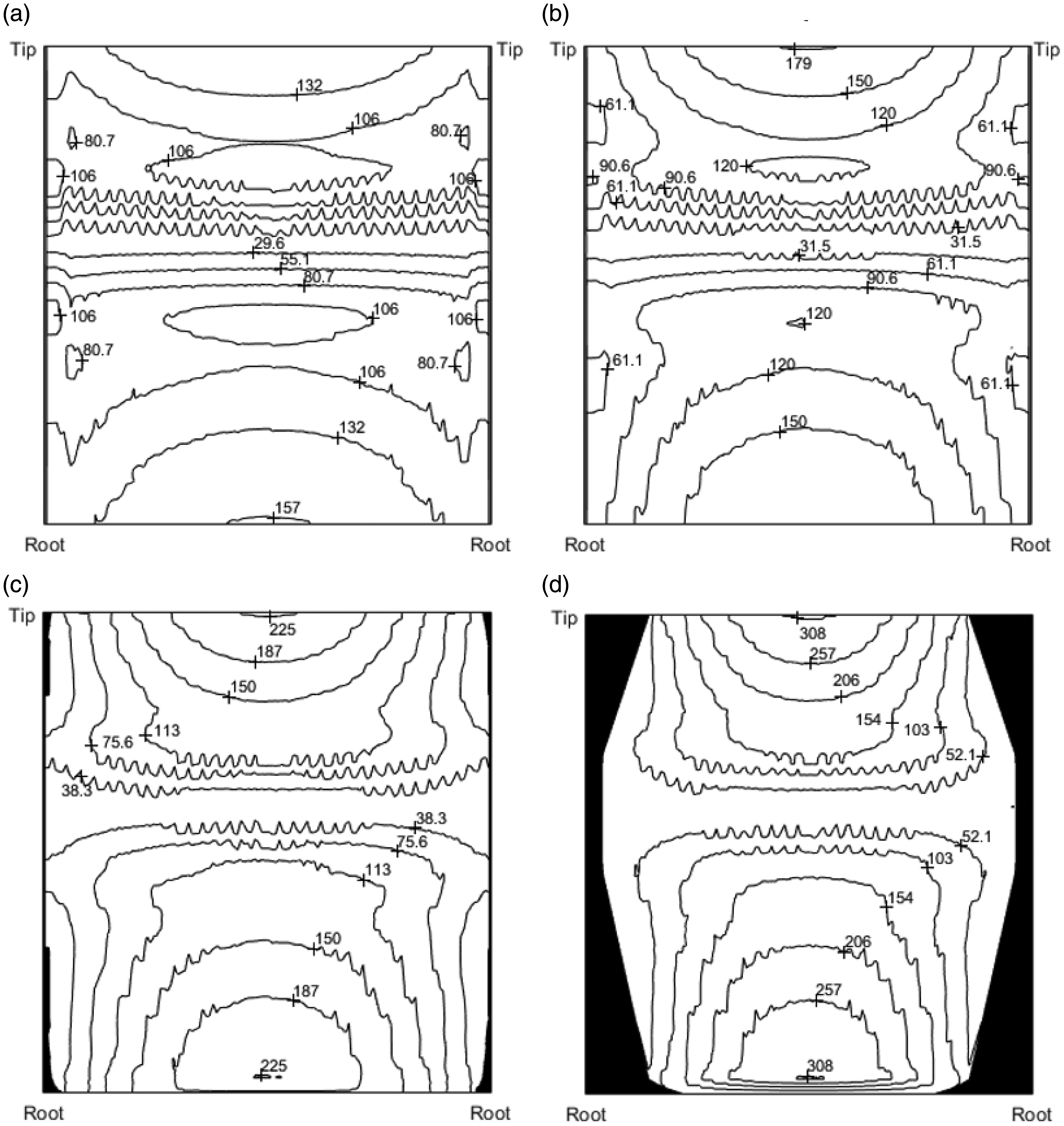
Figure 12(a) to (d) shows the contact power loss per unit length (W/mm), the integral of which along the tooth flank width yields the total instantaneous power loss. The contact losses are highest at the start and at the end of the meshing cycle, where the relative sliding velocities between the contacting teeth pairs are the highest. This corresponds to the tooth root and the tooth tip contacting regions. Similarly, power losses are the lowest where the gear contact passes through the pitch point (approximately halfway between the flank root and tip) and the contact experiences pure rolling condition for an involute spur gear pair. This trend is observed in Figure 12(a) to (d).
The crowning-induced curvature along the semi-major axis of the contact causes slight variations in the local surface geometry and induces some changes in the sliding velocities along the semi-major axis. Though this variation is small, its effects are exaggerated as the sliding velocity tends to diminish as the meshing contact approaches the pitch point. The influence on power losses can be seen as undulations in the contours of Figure 12(a) to (d).
With increasing crowning, Figure 12(a) to (d) shows a gradual shift and an increase in the contact losses towards the centre of the flank; a consequence of the pattern observed in the pressure isobars of Figure 11(a) to (d). When contact truncation occurs (Figure 12(a) and (b)), the power losses are higher in the localised regions along the edges of the flank which correlate to the areas of pressure concentrations due to stress discontinuity. However, even though the active flank area remains largely unchanged as in Figure 12(a) to (c), the distribution of contact losses is noticeably less severe with lesser crowning. This remains the case when considering the magnitude of the total contact power losses incurred for a complete meshing cycle.
Figure 13 shows a larger percentage and magnitude of contact losses with increasing crowning. While crowning is quite important in mitigating fatigue due to edge loading and thus enhances reliability, the results show how in some cases crowning can have a detrimental effect on efficiency.
Percentage variation in contact losses relative to Case A (‘A’ in figure) – stated values are for a single active flank.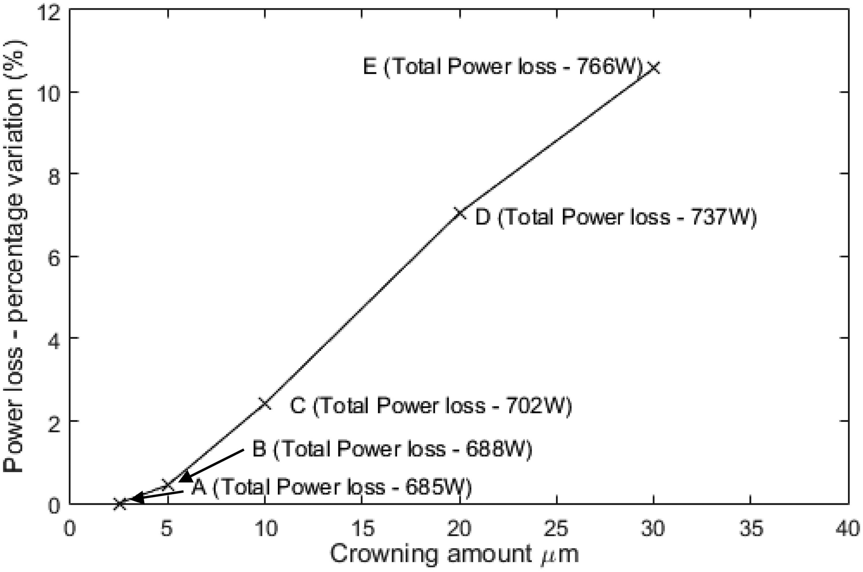
Figure 14(a) to (d) shows the lubricant centreline temperatures in the active flank area. Contact temperatures are highest at the root and at the tip as there is higher relative sliding velocities of the surfaces in these regions. Mid-meshing cycle, where the contact is in the region of the flank centre and sliding velocity is at its lowest, temperature rise is minimal as temperatures remain closer to the bulk temperature of 130 ℃.
Contact flash temperature distribution (℃) for a complete meshing cycle: (a) Case A, (b) Case B, (c) Case C and (d) Case D.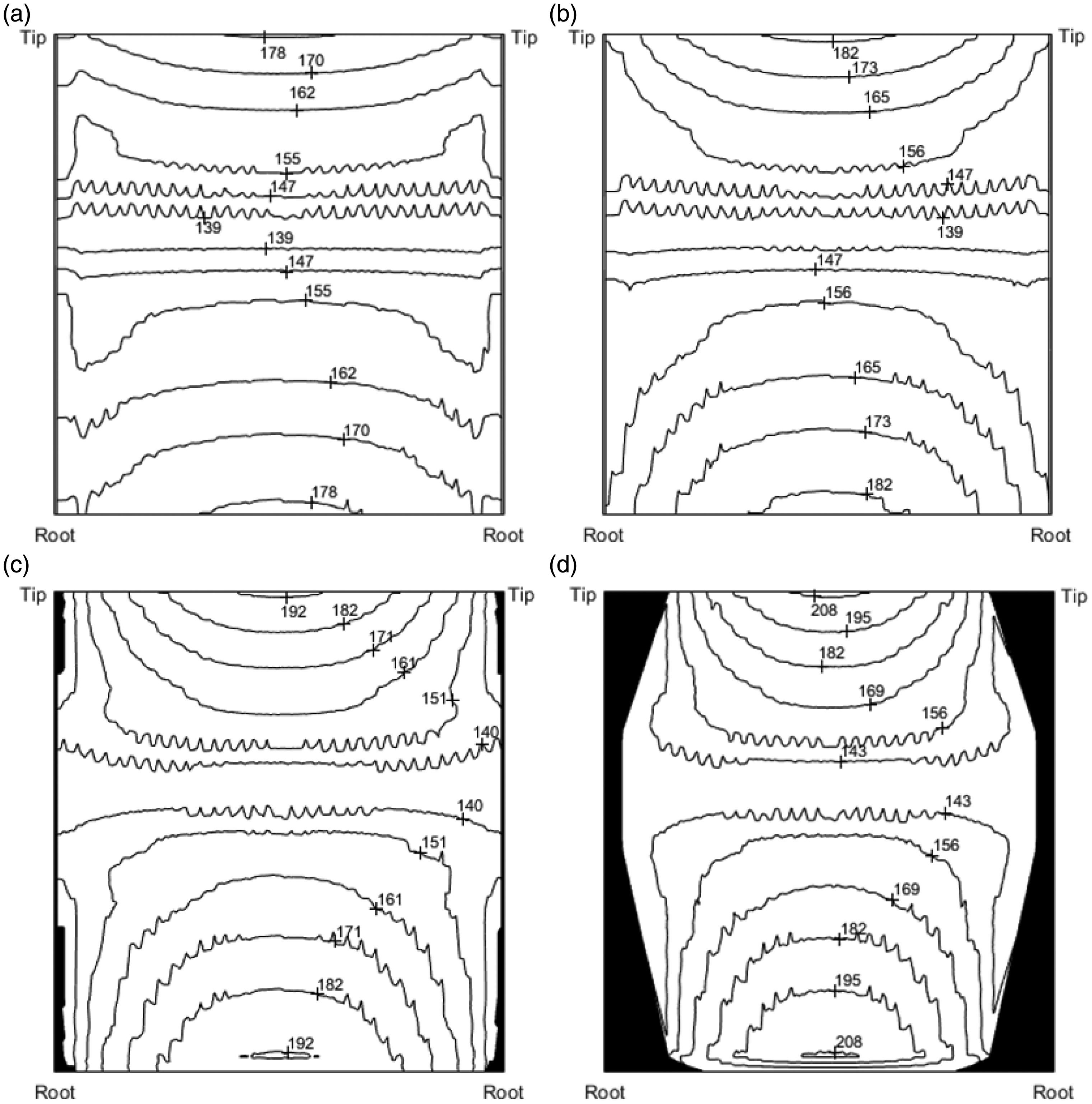
With increased crowning, Figure 14(a) to (d) shows a gradual increase in the maximum contact temperatures near the root and the tip of the flank. With contact truncation (Figure 14(a)), contact temperatures are observably higher in the localised regions along the edges of the flank. Mid-meshing cycle where the contact is in the vicinity of the flank centre, the temperatures at the edges of the flank rise by approximately 8 ℃ more than at the contact centre (Figure 14(a)). However, this variation becomes less pronounced with a slight increase in crowning, even when truncation and the stress discontinuity are still present (Figure 14(b)). When crowning sufficiently mitigates the edge pressure concentrations (Figure 14(c)), the temperature rises by approximately 15 ℃ more than in the case of Figure 14(a), even though the active flank area remains largely unchanged. This trend is further pronounced in Figure 14(d).
Conclusions
The high loading conditions experienced in compact high performance transmissions can cause contact footprint truncation in the meshing gear teeth pairs. This phenomenon causes stress discontinuities and generated high edge pressures. These pressure concentrations can be detrimental to system durability. They can also act to inhibit lubricant flow into these regions of the contact when lubricant nozzles are directed onto the side wall of the meshing gears. High pressure spikes have been shown to inhibit lubricant entrainment, resulting in very thin lubricant films in rolling element bearings 4 as well as cam-tappet contacts. 38
Crowning is used primarily as a palliative measure for misalignment issues which exacerbate the effect of edge pressure spikes. Crowning reduces the magnitude of high pressure spikes at gear flank edges and its associated undesirable repercussions. While the reduction of contact area generally implies lowered contact friction, the redistribution of pressure as the result of crowning can increase the average contact pressures over the contact footprint and thus increase the frictional power loss. The effect of starvation and cavitation is not included in the current analysis, both of which would have important repercussions as well.
Thermal analysis has shown that for the gears, lubricant and operating conditions considered in this study, peak contact temperatures rise by approximately 15 ℃ when crowning is introduced to reduce the edge pressure concentrations.
Footnotes
Declaration of Conflicting Interests
The author(s) declared no potential conflicts of interest with respect to the research, authorship, and/or publication of this article.
Funding
The author(s) received no financial support for the research, authorship, and/or publication of this article.