
Abstract
The broadband suppression of low-frequency noise in ship constitutes a critical engineering challenge, as it is directly related to acoustic stealth, vibration and noise control and equipment safety in marine vessels. This study presents a novel multilayer composite acoustic metamaterial comprising membrane, Helmholtz resonator, coiled channel and air cavity. The sound insulation mechanism of the proposed structure is investigated through finite element simulations using COMSOL Multiphysics and experimental validation. The study reveals the influence of parameters such as the stacking sequence of the constituent cells, membrane thickness, neck length and neck diameter of Helmholtz resonator and cavity depth on the sound insulation performance. Furthermore, the sound insulation effect resulting from coupled multi-cell synergistic interaction is explored. Experimental results demonstrate that the proposed composite acoustic metamaterial achieves an average sound transmission loss of 55 dB. The composite structure achieves high-efficiency sound insulation within 100–1000 Hz, with thickness equivalent to merely 1/70th of the acoustic wavelength at 100 Hz. The proposed composite acoustic metamaterial meets the dual requirements of low-frequency broadband sound insulation and lightweight configuration for practical engineering applications, thereby providing effective technical support and data support for low-frequency noise control in ships.
Keywords
Introduction
The rapid development of the shipbuilding industry has made low-frequency noise control a significant challenge for marine engineers.1–3 High-intensity noise poses significant risks to the physical and mental well-being of crew members, disrupts the stable operation of mechanical equipment and compromises the acoustic stealth performance of vessels. Investigating vibration and noise reduction technologies for ships is of significant importance for enhancing the military capabilities of naval vessels and protecting the marine ecological environment. Low-frequency noise is characterized by long wavelengths, extended propagation distances, strong penetration and slow attenuation, making it difficult to control effectively with conventional sound insulation materials. Acoustic metamaterials offer a new way of controlling low-frequency noise due to their subwavelength structures and unique properties such as negative equivalent mass density, 4 negative equivalent bulk modulus 5 and negative refractive index. 5 Currently, widely studied acoustic metamaterials include membrane-type, Helmholtz resonator-type, space-coiling-type and lattice-core sandwich structures.6,7
Membrane-type acoustic metamaterials (MAMs) are extensively studied due to their exceptional acoustic performance. Yang et al. 8 first proposed a MAM exhibiting negative dynamic mass, thereby overcoming the mass-law limitation at low frequencies. Building upon this foundation, subsequent research has introduced perforated membrane designs 9 and multi-layer stacked configurations 10 to expand the sound insulation bandwidth of MAMs. However, MAMs generally suffer from inadequate mechanical robustness and susceptibility to damage. To address this, Li et al. 11 proposed a multilayer honeycomb-cored MAM, enabling the tuning of the sound transmission loss peak by varying parameters such as the number of membrane layers, unit cell layers and honeycomb core thickness. Du et al. 12 systematically investigated the influence of mass block geometry, arrangement patterns and material properties on the sound insulation performance of MAMs. Xia et al. 13 achieved active magnetic-field tuning of sound insulation by embedding magnetic particles within the membrane. Inspired by spider-web morphology, Cao et al. 14 performed bio-inspired topological optimization, resulting in 19% reduction in structural mass alongside 61% enhancement in sound insulation bandwidth. Also, the effect of additives in membrane fabrication processes on acoustic performance has also been systematically examined.15,16
Helmholtz-type metamaterials exhibit excellent sound absorption and insulation performance, yet their noise reduction bandwidth is typically narrow. To achieve broadband noise reduction, researchers have introduced perforated panels integrated with Helmholtz resonators, enhancing the peak sound absorption/insulation and broadening the bandwidth through parameter optimization. 17 Yang et al. 18 achieved broadband sound absorption using a tunable parallel-cavity structure. Based on cavity topology grouping design, Bi et al. 19 demonstrated sound absorption coefficient exceeding 0.8 within 400–800 Hz using a structure with a thickness of only 40 mm. Kong et al. 20 proposed a butterfly-shaped double-layer configuration that incorporates a negative Poisson’s ratio structure, which enhances the low-frequency sound absorption performance while simultaneously improving the structural load-bearing capacity. Furthermore, by roughening the resonator necks to exploit viscous dissipation mechanisms, Yaw et al. 21 improved the low-frequency noise reduction effectiveness. Furthermore, researchers have investigated implementation of broadband sound absorption enhancement considering area coupling effect in multi unit parallel connection.22,23
Space-coiling acoustic metamaterials control low-frequency sound by elongating the propagation path of sound waves and incorporating viscous dissipation mechanisms. Man et al. 24 designed a space-coiling Mie resonant cavity based on the principle of self-similar fractals, enabling active manipulation of the radiated sound field. Liu et al. 25 proposed a porous labyrinthine metamaterial which exhibits effective absorption at low frequencies, with thickness of only 1/22 of the wavelength corresponding to its absorption peak. Chen et al. 26 introduced an ultra-thin graded arch-shaped metasurface, achieving dynamic tuning of the sound absorption bandwidth by manipulating the channel width.
Single-type acoustic metamaterials exhibit performance limitations and struggle to meet the requirements for low-frequency broadband sound insulation under complex operating conditions. To address this, researchers have proposed composite acoustic metamaterials. Examples include coupling Helmholtz resonators with membrane structures27,28 and combining Helmholtz resonators with coiled channels.29–33 These composite structures demonstrate significant broadband sound insulation performance within their target frequency ranges.
Figure 1 illustrates design process used in this study. To tackle the practical requirements of low-frequency broadband noise control in ship cabins and limited structural space, this paper proposes and designs a novel composite acoustic metamaterial structure based on multi-cell synergistic coupling. A combined approach utilizing COMSOL-based finite element simulation and experimental validation serves to systematically investigate the sound insulation characteristics of the structure. The effect of the unit cell arrangement pattern on the sound insulation capability within specific frequency bands is innovatively explored, demonstrating that precise targeted-frequency noise reduction is achieved by tailoring the arrangement and combination of unit cells. The mechanism by which multi-cell synergistic coupling extends the sound insulation bandwidth is explored. The proposed composite acoustic metamaterial successfully achieves broadband sound insulation within 100–1000 Hz. Compared with existing representative configurations, this structure provides a compact yet effective solution for low-frequency noise control, offering significant reference value for advancing the engineering implementation of acoustic metamaterials. Schematic diagram of the design aim and process.
Unit cell structure design and theoretical methodology
Structure design
The unit cell of novel composite acoustic metamaterial proposed in this study comprises membrane, perforated panel, neck-embedded Helmholtz resonator, coiled channel, air-backed cavity and stiffened backing plate, as illustrated in Figure 2(a). Schematic diagram of the unit cell: (a) Unit cell configuration, (b) disassembled unit cell structure, (c)–(e) Helmholtz resonator, (f) first-layer perforated panel, (g) slit-channeled cavity, (h) second-layer perforated pane, (i) coiled channel, (j) third-layer perforated panel and (k) back cavity.
Geometric parameters (in units of mm) of unit cell.
Theoretical model
The novel composite acoustic metamaterial proposed in this study comprises multiple structural components, with complex coupling interactions among its constituent units. When analyzing the noise reduction capability of the membrane-type acoustic metamaterials, this paper assumes a membrane in equilibrium within cartesian coordinate system, characterized by a surface tension α (N/m). When the membrane is subjected to an external force perturbation in the vertical direction, it undergoes deformation, generating transverse vibration in the vertical plane due to the restoring action of the surface tension α. Consider an infinitesimal surface element dxdy on the membrane. During deformation, its edges experience tensile forces from adjacent segments. The net force acting on this element in the direction perpendicular to its edges x and x+dx is expressed as Ref.
34
:

The total normal force acting on the entire surface element is:
Denote the mass per unit area of the membrane as the areal density 
Therefore
The assumed displacement u is:
Substituting Eq. (6) into Eq. (5):
Since the left-hand side of the equation depends solely on t, while the right-hand side relates exclusively to spatial coordinates x and y, both sides must equate to a common separation constant, denoted as −λ. The following two equations are derived:

When the membrane is a square membrane with side length a × b, let m and n denote the half-wavenumbers in the x direction and y direction. Substituting into Eq. (9):
Similarly, solving Eq. (8) yields:

When the membrane is square, then a = b. Eq. (12) reduces to:
Therefore
The result demonstrates that the natural frequency of MAMs is dependent on the membrane dimensions, areal density and surface tension.
This study introduces neck-embedded Helmholtz resonator (HR), where the neck is positioned within the resonant cavity to reduce the overall structural thickness, facilitating compact and lightweight applications. The simplified schematic of HR is shown in Figure 3(a), where h denotes the Helmholtz neck length, d represents the Helmholtz neck diameter, l
c
corresponds to the cavity length excluding the neck and l defines the cavity edge length. The equivalent circuit diagram of the HR is illustrated in Figure 3(b). Here, (a) Simplified schematic of HR and (b) equivalent circuit diagram of HR.
The total acoustic impedance ZHR of HR is expressed as Ref. 36,37:
ZHR can also be written as Ref. 36,37:


Eq. (17) and Eq. (18) are substituted into Eq. (16). When Im[ZHR] = 0, the system attains a resonant state, the resonance frequency can be formulated as:
Finite element model
Based on COMSOL Multiphysics, this paper establishes a multiphysics coupled finite element model integrating membrane structure, pressure acoustics, solid mechanics and thermoviscous acoustics modules, as illustrated in Figure 4. To simulate a practical ship engineering application scenario, a 5 mm steel plate is attached to the sound transmission side to represent an equivalent cabin wall structure. A background pressure field of a plane wave with an amplitude of 1 Pa is applied at the incident end. Perfectly Matched Layers (PMLs) are implemented at both ends to achieve non-reflective boundary conditions. The pressure acoustics interface governs the air domains, solid mechanics governs the membrane frame and metamaterial components, while the thermoviscous acoustics interface is applied to narrow regions such as the Helmholtz resonator neck, perforated plate apertures and coiled channels to account for thermoviscous loss effects. Acoustic-structure coupling boundary conditions are implemented at the interfaces between pressure acoustics and solid mechanics, as well as between thermoviscous acoustics and solid mechanics. Given that the structural impedance significantly exceeds the characteristic impedance of air, the structural walls can be treated as acoustically hard boundaries. Periodic boundary is applied to the unit cell model to simulate a two-dimensional infinite periodic structure. To balance computational accuracy and complexity, a variable meshing strategy is adopted. Swept mesh is used for the PMLs, while free tetrahedral mesh is applied to the remaining domains. The maximum element size is controlled to not exceed 1/6 of the wavelength of the minimum sound wave to ensure computational accuracy. While ensuring the accuracy of sound insulation performance prediction, the aim is to effectively reduce computational complexity and enhance simulation efficiency. Finite element model of the unit cell. Polyimide is used as the membrane material and its thickness is 0.2 mm with mass density of 1420 kg/m3, Young’s modulus of 2.65 GPa and Poisson’s ratio of 0.49. The membrane frame and metamaterial structural components are fabricated from photosensitive resin, characterized by mass density of 1120 kg/m3, Young’s modulus of 3.3 GPa and Poisson’s ratio of 0.41. The thickness of steel plate is 5 mm with mass density of 7850 kg/m3, Young’s modulus of 206 GPa and Poisson’s ratio of 0.3.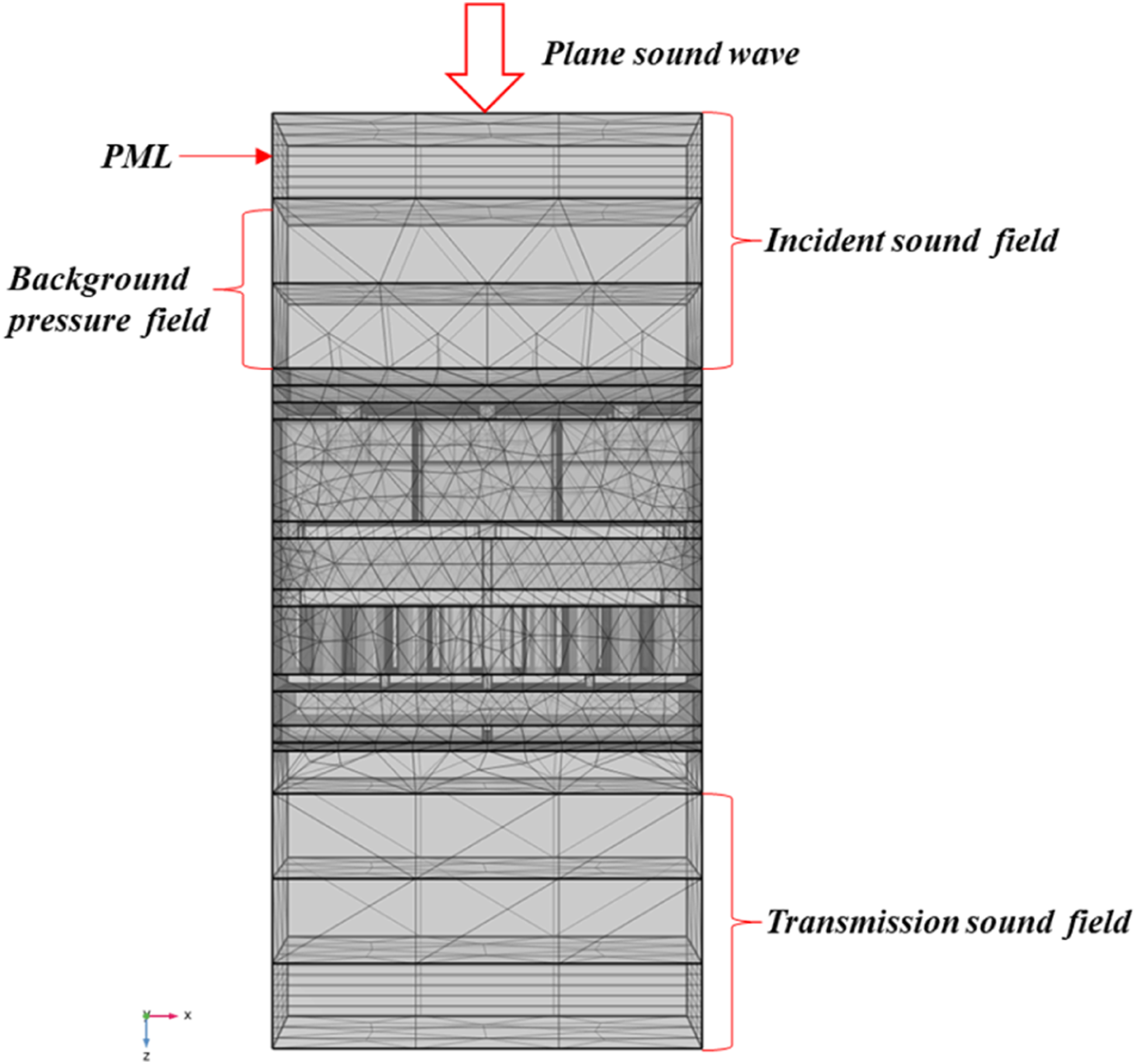
Sound insulation performance is typically characterized by the sound transmission loss (STL) (dB). Integral operators are defined at the sound wave incidence region and exit region, from which the incident sound power W
in
and transmitted sound power W
out
are derived
38
:

Thus, STL of the metamaterial structure expressed as:
Analysis and parametric study of the sound insulation performance for unit cell
Analysis of the sound insulation mechanism for unit cell
The sound insulation mechanism of the single-cell structure is investigated via finite element simulation. Figure 5(a) compares the STL of a 5 mm steel plate with the attached metamaterial unit and the standalone 5 mm steel plate within 100–1000 Hz. Compared to the standalone steel plate, the metamaterial exhibits six distinct STL peaks (labeled P) in the target frequency band. At the peak-valley positions, the STL generally increases with rising frequency, displaying relatively high peak values but considerable fluctuation amplitudes between peaks and valleys. (a) Comparison of unit cell and 5 mm steel plate in terms of STL and (b) STL of constituent structures.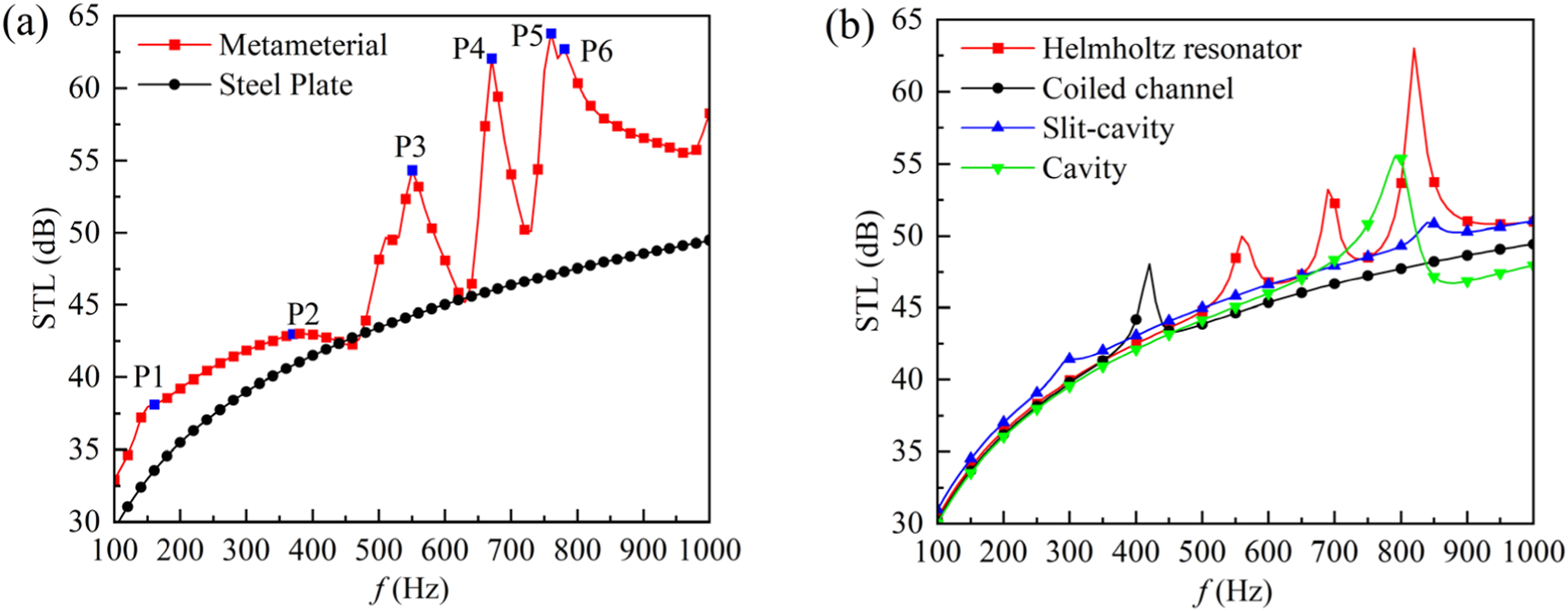
Figure 5(b) compares the noise reduction performance of each constituent unit acting independently.
The resonance characteristics of the Helmholtz resonator lead to a pronounced sound insulation peak in the mid-to-high frequency range, reaching up to 63 dB at 820 Hz, though with a relatively narrow effective bandwidth. The slitted cavity structure produces an insulation peak around 400 Hz, yet its high-frequency insulation performance is inferior to that of the Helmholtz resonator. The coiled channel dissipates acoustic energy through thermoviscous effects, resulting in a relatively flat STL curve. Its low-frequency sound insulation performance surpasses that of the previous two structures, with no obvious resonance dips and two notable insulation peaks present. Due to its simple configuration and lack of active acoustic energy dissipation or wave interference modulation mechanisms, the air-backed cavity offers limited overall insulation, exhibiting only one insulation peak near 790 Hz. The study indicates that each unit forms its own sound insulation peak in different frequency bands, effectively broadening the sound insulation bandwidth. Additionally, the coupling effects among the constituent units lead to deviations in the resonance frequencies of the single-cell structure.
Sound insulation performance of unit cell.
Figure 6 presents the acoustic pressure contour plot at the frequency corresponding to STL peak of the structure. Taking the first STL peak at 150 Hz as an example, the underlying sound insulation mechanism is analyzed. The incident sound wave enters the Helmholtz resonator through its neck. As the excitation frequency approaches to the resonant frequency of the Helmholtz resonator, the air inside the cavity is repeatedly compressed, leading to a significant increase in acoustic pressure and the onset of Helmholtz resonance. At this point, acoustic energy is localized within the cavity, thereby achieving sound insulation. Simultaneously, the acoustic pressure phase in the central resonant cavity is opposite to that in adjacent unit cells, indicating coupling effect between the resonators. This demonstrates that the resonance of multiple units does not occur independently but is influenced by inter-unit interactions. (a)–(f) Sound pressure distribution of structure at 150 Hz, 380 Hz, 550 Hz, 670 Hz, 760 Hz and 780 Hz.
The air cavity incorporating slit channels effectively lowers the frequency of the STL peak by extending the propagation path of the sound wave. Furthermore, an out-of-phase acoustic pressure field forms at the interface between the slits and the cavity, which suppresses sound wave transmission through destructive interference, thereby enhancing the sound insulation performance. Similarly, the coiled channel increases the effective length of the air passage. The narrow channel converts acoustic energy into thermal energy through viscous dissipation. The acoustic pressure gradually decreases from the interior to the exterior of the coil. The inner region reaches peak pressure, while the pressure in the outer cavity is nearly zero. This indicates that under excitation by the incident sound wave, a resonance forms between the inner section of the coiled channel and the air on both sides, localizing the sound wave within the internal structure and preventing its transmission.
The air-backed cavity induces intense vibration of the enclosed air via its resonant modes. Combined with the superposition effect of the out-of-phase acoustic fields, this further enhances the acoustic energy dissipation efficiency and significantly increases the STL. The formation of the first STL peak in the proposed novel multilayer composite acoustic metamaterial relies not only on the resonant characteristics of each individual unit but is also governed by the regulatory coupling effects between the units.
The P2 mode exhibits characteristics similar to those of P1. Figure 7 illustrates the sound pressure distribution within the coiled channel for both the P1 and P2 modes. However, in the P2 mode, the acoustic pressure intensity within the coiled channel progressively decreases from the outer to the inner region. Acoustic pressure is localized within the outer cavity, while the pressure in the inner cavity is nearly zero This indicates that sound waves within this frequency band can propagate normally through the coiled channel. In this case, the STL peak is primarily induced by the synergistic coupling between the Helmholtz resonator and the slit channel cavity. In the P3 to P6 modes, the Helmholtz resonator undergoes local resonance. Acoustic energy is localized within the unit cell and dissipated through friction between the air and cavity walls as well as viscous losses due to gas oscillation. Sound pressure distribution of the coiled channel in modes P1 and P2.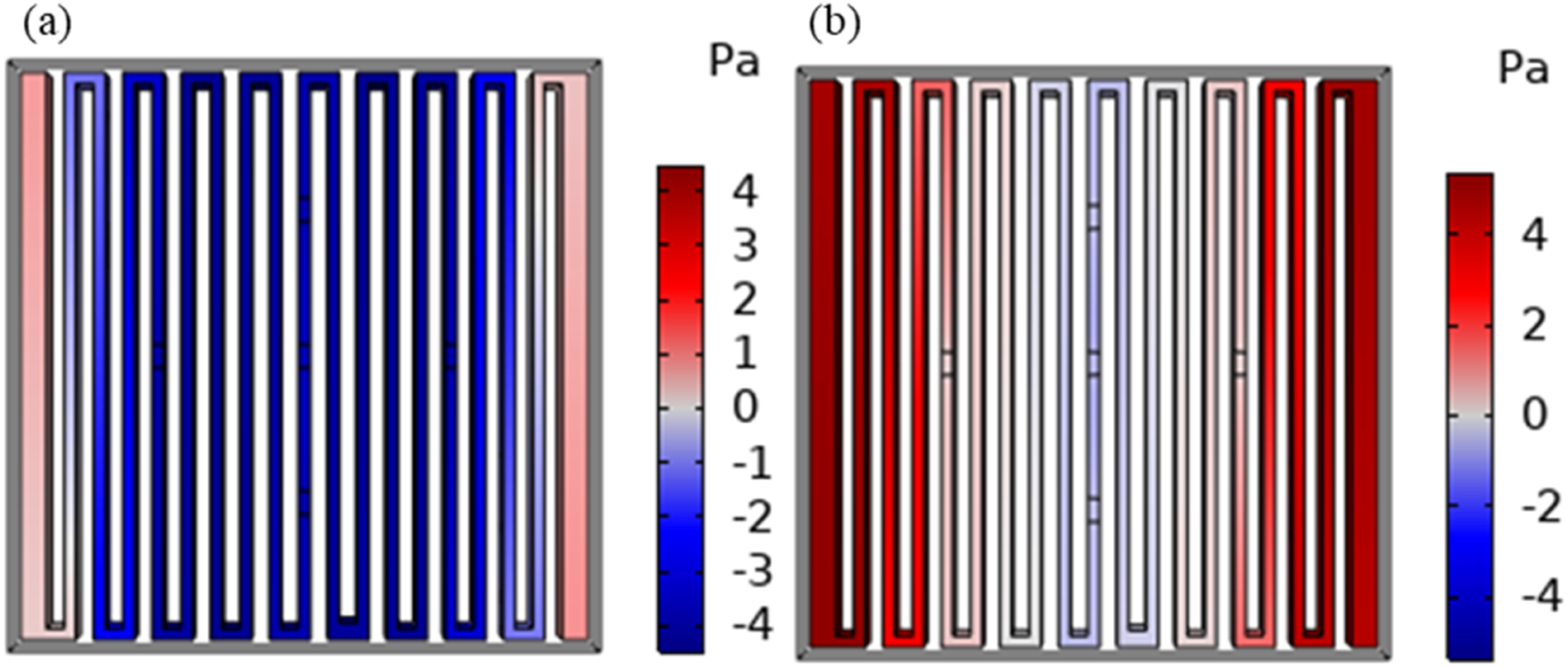
Figure 8 shows the vibration pattern of the membrane at the STL peak frequency. The membrane exhibits minimal displacement during vibration, operating in an anti-resonance mode. This mode induces strong reflection of the incident sound wave, promoting cancellation between the forward and backward propagating acoustic waves, thereby hindering sound wave transmission through the membrane and achieving enhanced sound insulation performance. As the acoustic boundary for the neck of the Helmholtz resonator, the vibration modal characteristics of the membrane correlate well with the acoustic pressure distribution inside the Helmholtz cavity shown in Figure 6. When the acoustic pressure phases within the Helmholtz cavity are opposite, the membrane vibrates in a direction opposing the incident sound wave. This observation indicates that the constituent units do not function independently; rather, there exists significant interaction and coupling effects among them. The acoustic responses of the individual units interact and synergistically regulate the overall sound insulation performance of the composite structure. (a)–(f) The membrane vibration modes at 150 Hz, 380 Hz, 550 Hz, 670 Hz, 760 Hz and 780 Hz.
Figure 9 illustrates the acoustic velocity field distribution within the Helmholtz resonator. When irradiated with the incident acoustic wave, the air at the neck orifice of the Helmholtz resonator vibrates intensely, imparting high particle velocity to the air molecules. The resulting friction with the neck walls converts acoustic energy into thermal energy, thereby dissipating energy localized within the neck region. Although the near-zero velocity field inside the cavity does not participate directly in energy dissipation, the substantial cavity volume provides significant acoustic mass, which shifts the sound insulation peak toward lower frequencies. Simultaneously, the vibration at the neck radiates sound waves outward, contributing to further energy dissipation. Concurrently, the membrane structure undergoes strong vibration, localizing the incident acoustic energy within the internal structure. (a)–(f) Acoustic velocity field distribution of the Helmholtz resonator at 150 Hz, 380 Hz, 550 Hz, 670 Hz, 760 Hz and 780 Hz.
Influence of unit arrangement on sound insulation performance
Composite acoustic metamaterial features constituent layers, each with independent noise reduction functionality. Helmholtz resonator, slit-channel cavity, coiled cavity and back cavity are freely combined to tune the sound insulation frequency band. Structure 1 is defined as a Helmholtz resonator, structure 2 comprises perforated panel and slit-channel cavity, structure 3 consists of perforated panel and coiled cavity and structure 4 includes perforated panel and back cavity, while the remaining structural components remain unchanged. By varying the arrangement sequence of these four layers, 24 distinct combination schemes are obtained.
STL of 24 combined structures of acoustic metamaterial.
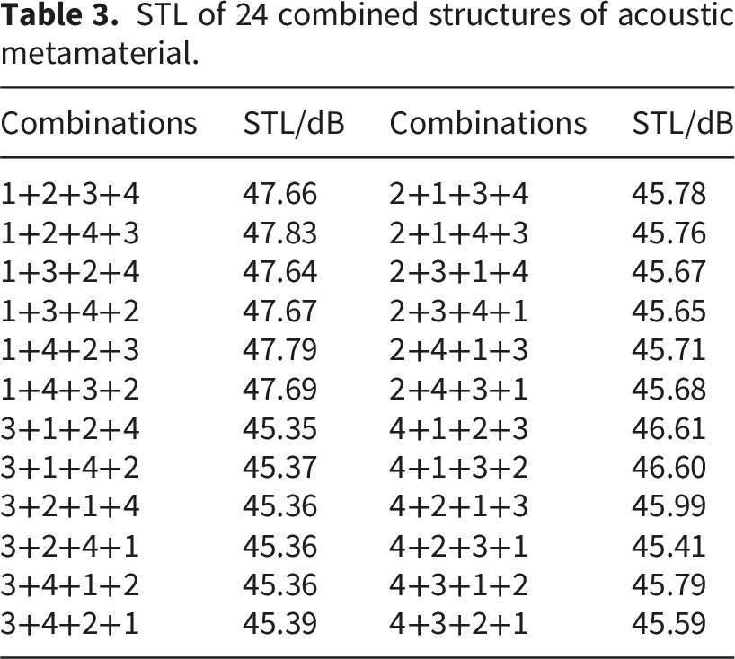
It is noteworthy that, regardless of whether the first layer is structure 2 or structure 4, combinations where the second layer is a Helmholtz resonator exhibit higher STL than other combinations with the same first layer. This suggests that placing structures with excellent high-frequency insulation performance in preceding layers and those effective at low frequencies in subsequent layers contributes to enhancing the overall sound insulation effectiveness. Furthermore, for the six combinations corresponding to the same first-layer structure, the extreme range of the average STL is less than 0.2 dB. This indicates that once the first-layer structure is determined, the arrangement order of subsequent structures has a minor influence on the overall STL.
To further analyze the sound insulation capabilities of different structural combinations within specific frequency bands, Figure 10 presents a comparison of the STL curves for 24 combinations. When the Helmholtz resonator is positioned as the first layer, the STL curves of all six combinations exhibit distinct multiple peaks and dips, indicating that the multi-layer composite structure possesses pronounced frequency-selective behavior. Furthermore, different combinations demonstrate a significant regulatory effect on the distribution of these STL peaks and dips. Specifically, placing structure 4 in the second layer can enhance low-frequency sound insulation performance, but it concurrently reduces the STL dip values in higher frequencies, which is detrimental to broadening the sound insulation bandwidth. In contrast, positioning it in a rearward location results in a smoother STL curve and more stable insulation performance. A comprehensive comparison reveals that: for emphasis on broadband sound insulation, combinations 1+2+3+4 and 1+3+2+4 exhibit significant STL peaks in the mid-to-high frequency range while maintaining stable performance in the mid-to-low frequencies, offering superior overall performance. For emphasis on enhancing low-frequency sound insulation, combinations 1+4+2+3 and 1+4+3+2 demonstrate better performance within 200-500 Hz. Combination 1+2+4+3 shows greater fluctuation in overall sound insulation performance, but it displays outstanding performance in high-frequency sound insulation. (a)–(d) Comparison of STL for different configurations.
When the slit-channel cavity is positioned in the first layer, the STL curves for all six configurations exhibit similar trends across the entire frequency band, increasing steadily with rising frequency. The subsequent arrangement of structural units has a relatively weak influence on the overall sound insulation performance. The primary effect is fluctuations in acoustic energy dissipation efficiency caused by the overlapping of the resonance frequencies of individual units, leading to shifts in the frequencies of the STL peaks.
When the coiled channel is positioned in the first layer, the STL curves for all six configurations are nearly coincident across the entire frequency band with only minor fluctuations. The coiled channel primarily provides sound insulation through thermoviscous effects. After the incident sound wave is dissipated by structure 3, the mid-to-high-frequency acoustic energy is significantly attenuated. Consequently, the resonance-based tuning mechanisms of subsequently arranged structures can hardly exert a differential effect, rendering the subsequent arrangement insignificant for modulating the overall sound insulation performance.
When the back cavity is positioned in the first layer, the STL curves for all six configurations show pronounced fluctuations. Among these, when structure 1 is placed in the second layer, its resonant effect generates a distinct STL peak in the mid-to-high frequency range. This results in a more stable STL curve within 450–1000 Hz and reduces the amplitude of fluctuations compared to other configurations. When structure 2 is placed in the second layer, the incident sound wave passes directly through the slit-channel cavity, leading to inferior sound insulation effectiveness. When structure 3 is placed in the second layer, the structure exhibits weak sound insulation performance at low-to-mid frequencies, as the thermoviscous loss mechanism of the coiled channel fails to effectively suppress sound wave propagation.
Placing the Helmholtz resonator in the first layer enhances the overall sound insulation performance of the structure, whereas positioning the coiled channel as the initial layer yields the weakest overall performance. This indicates that the thermoviscous dissipation mechanism of the coiled channel is better suited for meeting the requirement of secondary energy dissipation within the mid-to-rear sections of the structure. Each specific combination corresponds to a dominant sound insulation band. Precise noise reduction in targeted frequency ranges can be achieved by adjusting the arrangement and combination of the unit cells. In practical engineering, the appropriate configuration is selected based on the specific noise spectrum characteristics.
The influence of structural parameters on sound insulation performance
Although the STL curve of a single unit cell exhibits multiple low-frequency sound insulation peaks, the significant fluctuations between peaks and valleys, along with the relatively narrow sound insulation bandwidth, considerably limit its engineering applicability. To address this, the present study broadens the insulation bandwidth by coupling multiple unit cells with different parameters. Previously, the influence of structural parameters on the sound insulation performance of a single cell is investigated. These parameters specifically include the membrane thickness, the neck length and neck diameter of the Helmholtz resonator, the cavity length of the Helmholtz resonator, the cavity length of the slit channel, the length of the coiled channel and the depth of the air back cavity. The parametric influence study is conducted using the control variable method. The initial parameters are consistent with those specified in the Structure Design and subsequent analyses are performed by varying solely the target parameter.
The variation of the single-cell STL with parameters is shown in Figure 11. Figure 11(a) shows that the membrane thickness does not affect the frequency and peak value of the first sound insulation peak, but it can effectively adjust the peak values and bandwidth of other sound insulation peaks. When the membrane thickness increases, the increase in surface density weakens the acoustic radiation effect, thereby improving the structure’s sound insulation performance. However, the STL at the first sound insulation dip decreases correspondingly, indicating that the membrane thickness should not be excessively large. Figure 11(b) illustrates the influence of the neck length of HR on the structure’s sound insulation performance. As the neck length increases, the structural resonance frequency decreases, causing the sound insulation peak to shift toward lower frequencies. The sound insulation bandwidth remains largely consistent across different neck lengths, but differences exist in the peak values of the insulation peaks. Among these, the peak value of P3 remains essentially unchanged, while P4 shows a difference of approximately 1 dB and P5 shows a difference of approximately 2 dB. The expression for the characteristic frequency of the embedded-neck Helmholtz resonator derived in Eq.(19) indicates that a larger neck length results in lower resonance frequency. This theoretical conclusion aligns with the simulation results presented in this chapter, validating the effectiveness of neck length adjustment. STL of the unit cell for different parameters: (a) Membrane thickness, (b) neck length of HR, (c) neck diameter, (d) cavity length of HR, (e) cavity length of the slit channel, (f) cavity length of the coiled channel and (g) cavity length of the air backing cavity.
Compared to the neck length of HR, the neck diameter has a more complex influence on the structure’s sound insulation performance, making it difficult to achieve both high-efficiency sound insulation and frequency tuning simultaneously. Theoretical analysis indicates that reducing the neck diameter decreases the cross-sectional area of the resonator, thereby lowering its resonance frequency. However, an excessively narrow neck restricts the airflow velocity, weakening the acoustic energy dissipation within the neck. Conversely, when the neck diameter exceeds a critical value, the effect of viscous losses in the neck diminishes significantly. Under these conditions, acoustic energy entering the cavity cannot be effectively dissipated through reflection and resonance mechanisms, which consequently degrades the sound insulation performance. Figure 11(c) shows that as neck diameter increases, the STL peak shifts to higher frequencies and its bandwidth broadens. This occurs because, with a larger neck diameter, the primary sound insulation mechanism of the Helmholtz resonator shifts from thermoviscous losses in the neck to the resonance of the entire cavity. An overly large neck diameter reduces the depth of the STL trough, which is detrimental to broadband noise reduction. Furthermore, when a combination of multiple neck diameters is employed, the STL curve exhibits multiple distinct peaks and the amplitude difference between peaks and troughs is significantly reduced. This demonstrates that optimizing the parameters of the multi-diameter neck combination can effectively enhance the structure’s broadband sound insulation performance.
The length of the Helmholtz resonator governs the sound insulation performance by altering the volume of the resonant cavity. As shown in Figure 11, the sound insulation peak frequency decreases with increasing cavity length L1, while the STL at the resonance frequency remains relatively high and is not significantly affected by variations in L1. Increasing L1 can enhance the low-frequency sound insulation effect, but it also leads to an increase in the overall structural thickness, which may be unfavorable for practical applications. Further studies indicate that changes in the lengths of the slotted-channel cavity L2, the coiled channel L3 and the air back cavity L4 have a minor influence on the STL, merely causing slight low-frequency shifts in the insulation peak, as shown in Figure 11(e)–(g). This suggests that, compared with L1, the dimensional parameters of the auxiliary cavities play a relatively limited role in regulating the overall sound insulation characteristics. Nevertheless, these auxiliary cavities cannot be omitted from the composite structure, as the overall sound insulation performance of the composite acoustic metamaterial results from the synergistic coupling effect among multiple constituent units. Each unit fulfills a specific sound insulation function within different frequency ranges and the cavity structures effectively extend the acoustic propagation path, providing the necessary space for sound reflection, scattering and resonant dissipation. Therefore, these cavities remain one of the key factors enabling the overall sound insulation performance.
Multi-cells in parallel for ultra-broadband sound insulation
Multi-cell synergistic coupling
Based on the acoustic performance analysis of the novel composite acoustic metamaterial unit cell proposed in this paper, the structure exhibits excellent tunable sound insulation characteristics under lightweight and thin-thickness conditions. However, the sound insulation bandwidth of the single unit cell in the low-frequency range is relatively narrow, making it difficult to meet the requirements for low-frequency broadband noise reduction. Studies indicate that coupling multiple sound insulation units with different parameters can effectively broaden the noise reduction bandwidth under the same thickness.39,40 Therefore, this section proposes a parallel arrangement of multiple unit cells with different resonant frequencies, aiming to achieve low-frequency broadband sound insulation.
The parallel structural configuration is illustrated in Figure 12. This configuration comprises four sound insulation units. Except for the neck length of the Helmholtz resonators, all other parameters remain as specified in Structure Design. The neck lengths for units 1 to 4 are 5 mm, 6 mm, 7 mm and 8 mm, respectively. To ensure engineering practicality, the overall structure is designed as a regular cuboid measuring 101 mm × 101 mm × 45 mm. This design maintains the functional independence of each unit while enhancing spatial efficiency through a compact layout41–43. Parallel structure configuration.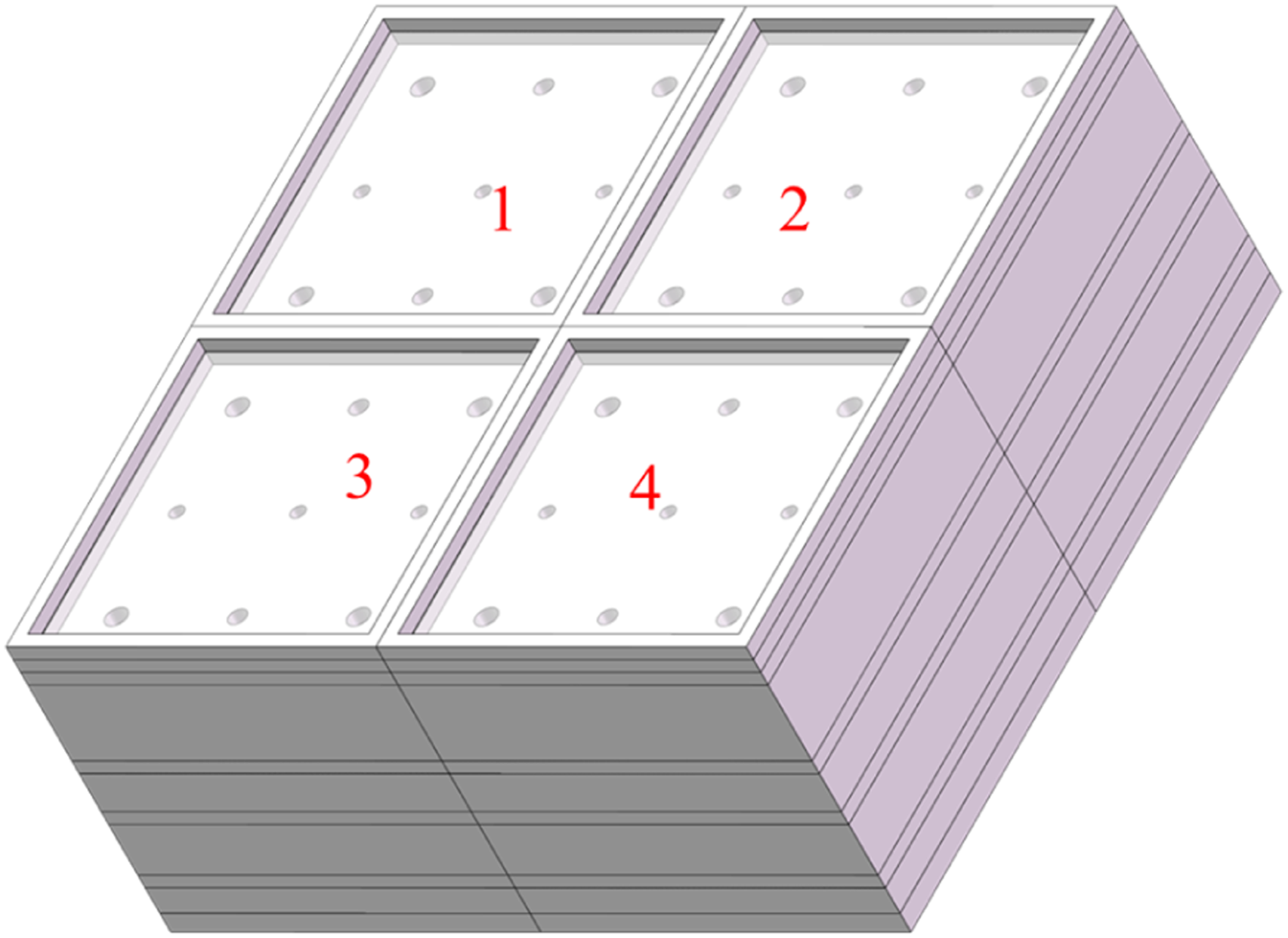
Figure 13 shows the STL characteristics of the parallel structure and its four constituent unit cells. The analysis demonstrates that the average STL for unit 1, unit 2, unit 3 and unit 4 are 47.6 dB, 47.5 dB, 47.5 dB and 47.4 dB, respectively. For the coupled configuration, the average STL is 47.5 dB, indicating negligible difference in overall sound insulation performance among these configurations. However, the STL curve of a single unit cell exhibits pronounced troughs between adjacent isolation peaks, preventing the formation of a continuous broadband sound insulation profile. By connecting four unit cells with different resonant frequencies in parallel, the coupling effect induced by parameter variations generates superimposed isolation peaks within 500–750 Hz. This mechanism compensates for the sound insulation gaps inherent in single-cell structures. This form of coupling, based on the interaction between units with distinct parameters, enables the coupling and collaboration of multiple unit cells within a limited spatial volume. Consequently, the structure forms a continuous and highly effective sound insulation band within 100–1000 Hz. Furthermore, the overall thickness of the structure is only approximately 1/70th of the wavelength of 100 Hz. This achieves the goal of lightweight design while maintaining high sound insulation performance, underscoring its significant practical application value. STL of the parallel structure and its four corresponding unit cells.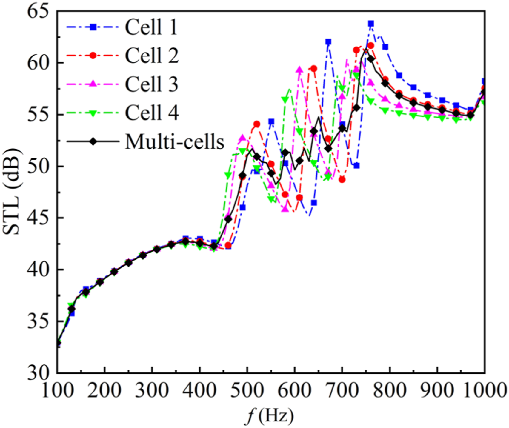
Experimental validation
To evaluate its sound insulation performance, the STL of the proposed novel composite acoustic metamaterial is measured via an impedance tube test. The experiment is conducted based on the standard four-microphone transfer matrix method. By measuring the sound pressure levels at four fixed positions under different termination conditions, the transfer matrix is derived, from which STL of the test material is determined. The experimental setup is illustrated in Figure 14(a). The experimental system consists of SW F100 impedance tube, VA-Lab software module, NI9235 collecting instrument, PA50 power amplifier and MPA416 microphones, covering an effective measurement frequency range of 50–1600 Hz. The specimen is fabricated via 3D printing using photopolymer resin. Given the structural complexity, a layer-by-layer printing approach followed by manual bonding is employed to prevent the entrapment of uncured liquid resin (Figure 14(b)). The final physical prototype is presented in Figure 14(c). (a) Experimental setup, (b) 3D-printed layered model and (c) physical prototype.
Unit cell analysis employs periodic boundary conditions to simulate two-dimensional infinite periodic structure, whereas the actual experiment utilizes hard-walled boundary conditions within an impedance tube. Therefore, this section adopts the finite element method to calculate the STL of the metamaterial under clamped boundary conditions and compares it with experimental results, as shown in Figure 15. The frequency range of 100–260 Hz is identified as the stiffness-controlled region, where STL decreases as the frequency increases. Subsequently, the structure enters the damping-controlled region. The first sound insulation peak occurs at 348 Hz, attaining STL of 61.7 dB; the second sound insulation peak appears at 728 Hz, achieving STL of 59 dB. Throughout this range, the STL consistently exceeds 50 dB. Owing to resonance effects, a series of sporadic, less pronounced secondary sound insulation peaks is observed between the two primary peaks. The results prove that the simulation curve agrees well with the trend of the experimental data, with the simulation curve being smoother, while the experimental data exhibit significant fluctuations across the entire frequency band. The sound insulation peaks obtained from simulation and experiment exhibit slight deviations: the first peak shifts by 242 Hz, while the second peak shifts by 16 Hz. Furthermore, STL predicted by the simulation model is generally higher than the experimental values at corresponding frequencies. The average STL from the simulation is 62 dB, compared to 55 dB from the experiment, resulting in an overall discrepancy of 7 dB. Based on the above description, the discussion will proceed from two aspects: sample fabrication and experimental testing. Comparison of STL between simulation and impedance tube testing.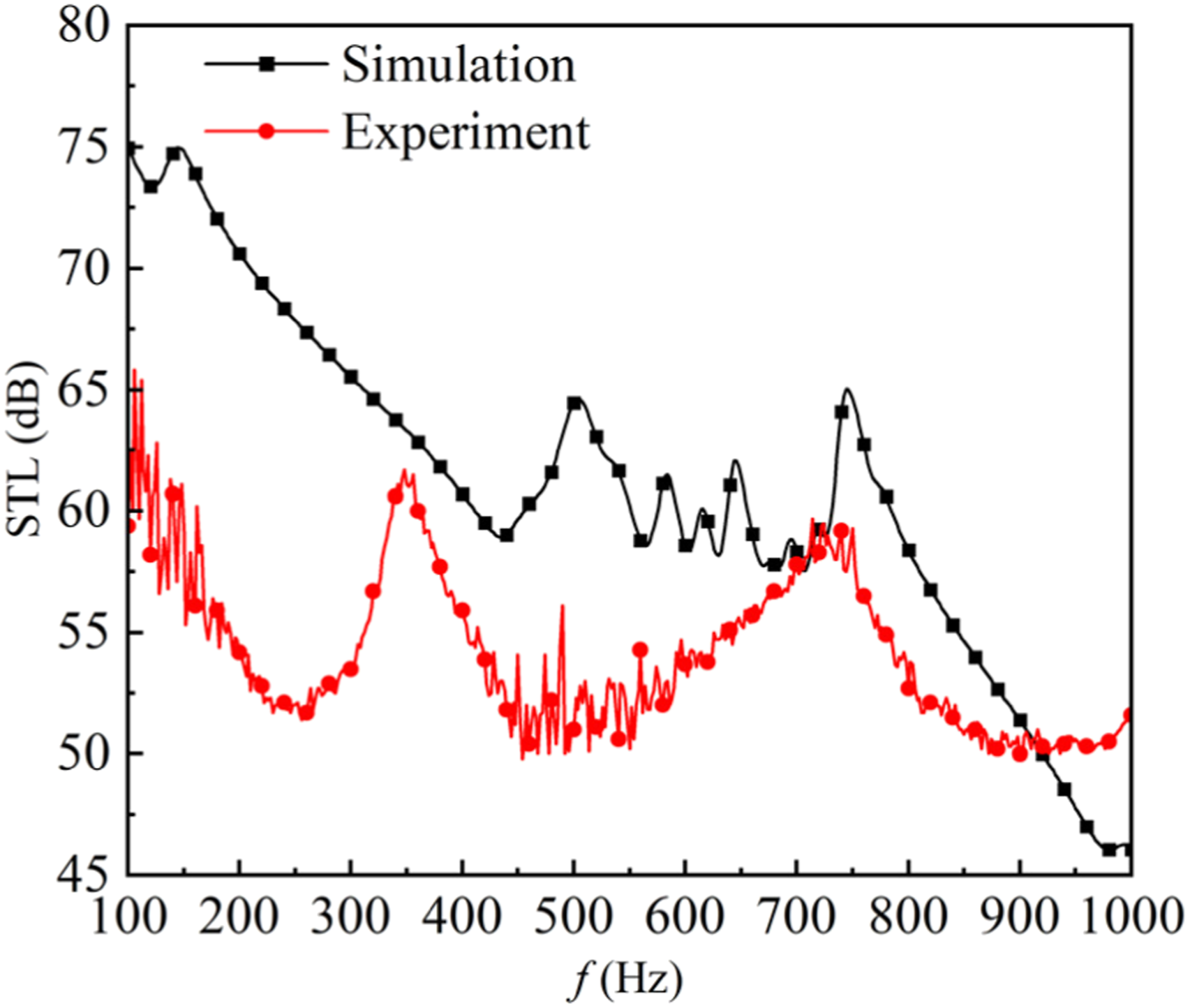
Firstly, discrepancies arise from fabrication tolerances in the samples. Layer-by-layer printing and adhesive sealing introduce positional deviations, making it difficult to achieve an ideal airtight seal. This compromises the sealing effect, leading to a more complex structural vibration mode and a weakening of both the resonant and anti-resonant effects. Simultaneously, the adhesive bonding between the membrane and the frame prevents perfect conformity, indirectly affecting the effective vibrating area of the membrane. Secondly, during experimental testing, fluctuations in the sound source signal cause oscillations in the measured STL curve. The actual boundary conditions are difficult to perfectly match the simulation setup. Furthermore, the sample size is smaller than the impedance tube diameter. Even with sealing using petroleum jelly and tape, sound leakage phenomena persist, resulting in experimental data that is generally lower than the simulated values. Although the aforementioned factors contribute to certain differences between the experimental and simulation results, the overall trends of the STL curves show good agreement. This demonstrates the validity of the finite element simulation.
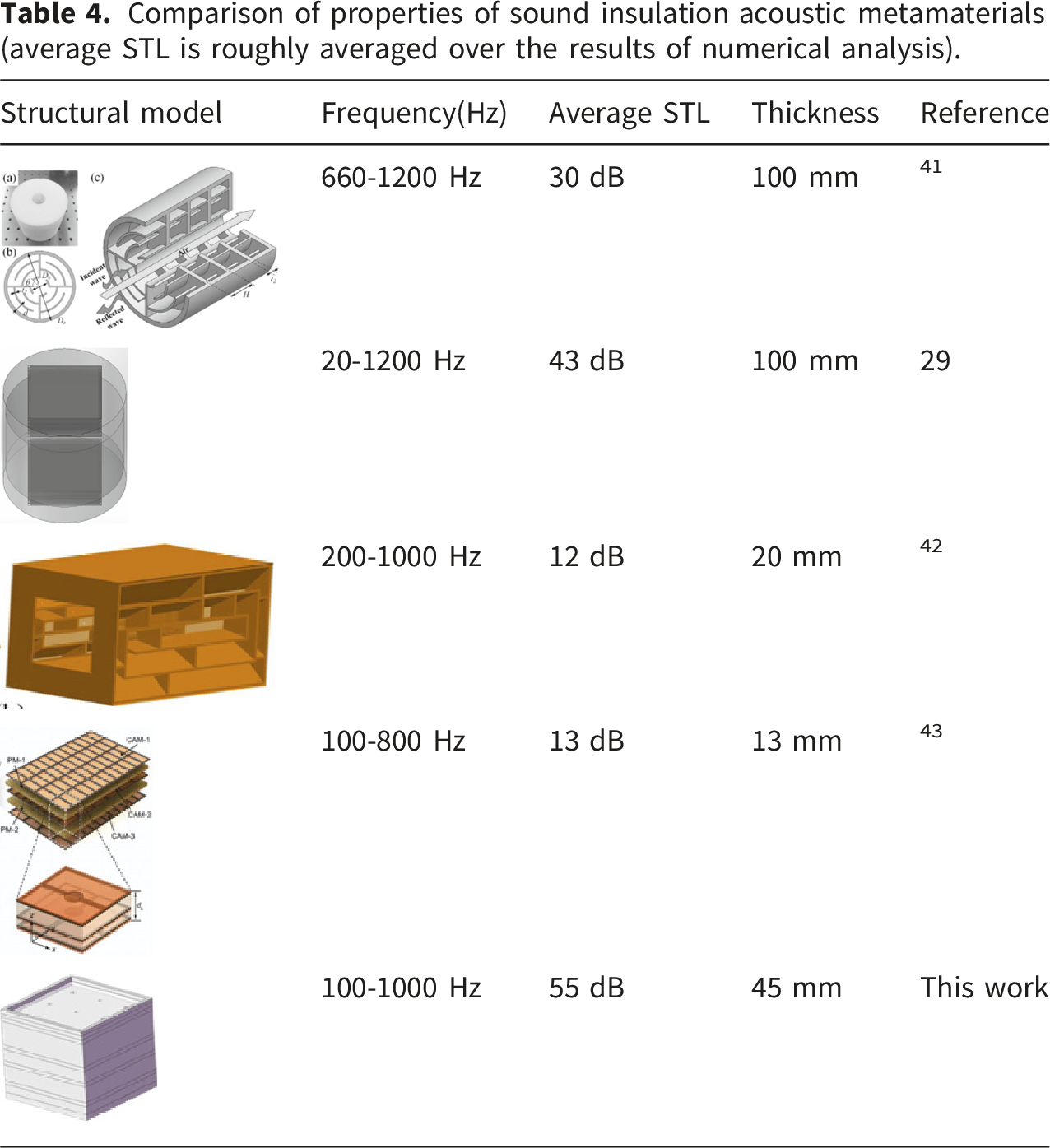
Comparison of properties of sound insulation acoustic metamaterials (average STL is roughly averaged over the results of numerical analysis).
Conclusion
In order to mitigate the problem of low-frequency noise aboard ships, this paper proposes a novel multilayer composite acoustic metamaterial for low-frequency broadband sound insulation. The structure primarily consists of membrane, Helmholtz resonator, coiled channel and air cavities. Through theoretical analysis, finite element simulation and experimental verification, the sound insulation performance of the structure is systematically investigated. The main research findings are as follows: (1) The novel composite acoustic metamaterial designed in this paper achieves effective sound insulation within 100–1000 Hz with thickness of 1/70 of the wavelength, thereby meeting the dual requirements of low-frequency broadband sound insulation and lightweight construction in naval engineering. Furthermore, studies on the unit arrangement sequence reveal that placing the Helmholtz resonator in the first layer yields the optimal sound insulation performance, whereas positioning the coiled channel in the first layer results in the weakest performance. This indicates that the location of each unit in the acoustic energy transmission path directly influences its synergistic coupling effect. (2) The structural parameters of the constituent cells exhibit well-defined tuning effects on the sound insulation performance: Membrane thickness can modulate the bandwidth of the sound insulation peak; increasing the neck length of the Helmholtz resonators shifts the sound insulation peak towards lower frequency; enlarging the neck diameter shifts the peak towards higher frequency and broadens the bandwidth; while increasing the cavity depth of the Helmholtz resonator enhances low-frequency sound insulation but at the cost of greater structural thickness. (3) A multi-cell parallel configuration effectively bridges the transmission loss gap inherent in a single-cell structure by coupling units with different resonant frequencies, thereby generating superimposed STL peaks within 500–750 Hz. This mechanism achieves continuous and efficient sound insulation within 100–1000 Hz. (4) Experimental validation demonstrates that the trends of the simulated and measured STL curves are in good agreement. Although certain deviations exist due to factors such as manufacturing tolerances and boundary conditions, the results effectively confirm the feasibility of the proposed composite metamaterial structure and the reliability of the simulation model.
In summary, this study proposes a novel composite acoustic metamaterial characterized by a compact structure and significant lightweighting benefits. Through the multi-cell synergistic coupling mechanism, it achieves effective low-frequency broadband sound insulation. This work provides a new solution and theoretical basis for low-frequency noise control in ship cabins.
Footnotes
Author contributions
All authors contributed equally and approved the final version of the current manuscript.
Funding
The authors received no financial support for the research, authorship, and/or publication of this article.
Declaration of conflicting interests
The authors declared no potential conflicts of interest with respect to the research, authorship, and/or publication of this article.
Data Availability Statement
Current submission does not contain the pool data of the manuscript but the data used in the manuscript will be provided on request.