
Abstract
In order to suppress lateral vibration transmission and reduce acoustic radiation of a shafting-hull coupled system, a new approach using electromagnetic bearings in the shafting system is proposed. The dynamic characteristics of the electromagnetic bearings, especially the equivalent stiffness and damping as well as the applicable scope of linearization of the electromagnetic bearings, are analysed at first. With the equivalent parameters, a dynamic model of the shafting-hull coupled system is established subsequently by using the frequency response synthesis method to derive frequency response functions associated with the lateral vibrations. Finally, the influence of the control parameters of the electromagnetic bearings on vibration transmission in the shafting-hull system is studied. Analysis results indicate that lateral vibration responses are suppressed significantly when electromagnetic bearings are introduced into the shafting-hull system, and as a result, sound radiation of the system is reduced, which demonstrates that the proposed approach is effective in controlling vibration transmission in the shafting system.
Introduction
The shafting system excites the hull structure through its bearings and causes acoustic radiation. 1 A propulsion shafting system usually contains a rear bearing, a front bearing and a thrust bearing. Among them, the rear bearing is water-lubricated rubber bearing, which may cause vibration and friction noise in the low-speed condition due to poor lubrication. It has been revealed that the radiated noise is induced mainly by longitudinal or lateral vibration. 2 It is possible to reduce vibration in the hull structure and the induced acoustic radiation by controlling vibration transmission through the bearings. The longitudinal vibration of a shafting system is transmitted to the hull structure mainly through the thrust bearing. However, the transmission of lateral vibration is much more complicated and generally the water lubricated bearings are the main transmission paths. As a result, controlling lateral vibration transmission is much more difficult.
In fact, investigations on the longitudinal vibration control of shafting systems are reported frequently so far,2–4 but there are few studies on lateral vibration transmission control. Cao et al. 5 studied the influence of lateral vibration of shafting systems on the underwater structural acoustic radiation. Mauro Caresta 6 investigated the use of inertial actuators to reduce the sound radiation of a hull structure, where the actuators were arranged in circumferential arrays and attached to the prow end cone.
In this paper, electromagnetic bearings (EMBs) are proposed to work in parallel with the rear bearing in order to reduce friction and the lateral vibration transmission. Dynamics of EMBs are dependent mainly on the implemented control laws, and especially the stiffness and damping of active magnetic bearings are adjustable. 7 A variety of controllers for EMBs have been proposed.8–15 EMBs are mainly used in high-speed centrifugation, 16 flywheel energy storage system17,18 and turbomachinery,19,20 etc. For vibration control of rotor-bearing systems, EMBs are commonly used. Amer et al. 21 investigated the dynamic behavior of a simple rigid disk-rotor supported by active magnetic bearings. Das et al. 22 used electromagnetic actuator to control the coupled flexural-torsional vibration in a flexible rotor-bearing system. Roy et al. 23 studied the influence of the viscoelastic control law on the dynamic behavior of a rigid rotor-shaft system with active magnetic bearings. Matsushita et al. 24 proposed aseismic vibration control of flexible rotors with active magnetic bearings to suppress rotor vibration generated by the earthquakes. In these investigations, EMBs are used for vibration control of rotor-bearing systems with rigid or elastic bases. In this paper, the shafting system and the hull structure are considered as whole system, but no investigation has been reported on the shafting-hull coupled system with EMBs, which has the advantages of being free of friction and lubrication and renders the possibility of controlling vibration transmission.
For linear vibration systems, the differential equation of motion can be expressed as
25

For theoretical investigation, a dynamic model of the shafting-hull system is necessary. Existing modelling methods involve analytic methods,26,27 semi-analytical methods 28 and numerical methods. 2 For complicated systems, such as the shafting-hull coupled system, a dynamic model cannot be easily obtained by analytic methods and usually numerical methods, such as the finite element method (FEM), have to be applied. However, it is also inconvenient for numerical methods to analyze the influence of physical parameters. In this paper, a hybrid method is adopted. The FEM is used at first to obtain the frequency response functions (FRFs) of the shaft and the hull systems, respectively, and then the frequency response synthesis method is applied to establish the dynamic model of the shafting-hull coupled system, which makes it easier to study the influence of bearing parameters.
The discussion is organized as follows. The next section gives the equivalent stiffness and damping of the EMBs. The subsequent section establishes the dynamic model of the shafting-hull system. Then, simulation results and discussions are presented. Finally, conclusions are summarized.
Stiffness and damping of EMBs
In a simple EMB system, displacements of the rotor from its reference position are measured by the sensors and control signals are amplified by the power amplifier in order to generate necessary currents for EMBs. As a result, magnetic fields in the EMBs and desired magnetic forces acting on the rotor are generated. The closed loop system is stabilized by a feedback control law. The stiffness, damping and stability of the system depend mainly on the implemented control law.
The differential driving mode of a 2-DOF EMB is illustrated in Figure 1, where i0 is the bias current, while iy and iz are the control currents in the vertical (Y) and horizontal (Z) directions, respectively. In terms of differential driving mode, one pair of magnetic poles are driven by the sum of the bias and control currents, and the other by the difference. 7 In order to simplify control of the EMB, four pairs of coils or eight magnetic poles are commonly used in a radial magnetic bearing and they are assumed to have identical structures. The magnetic poles are placed symmetrically with symmetric power amplifier circuits, which enable the bearing to attract the rotor along two orthogonal axes.
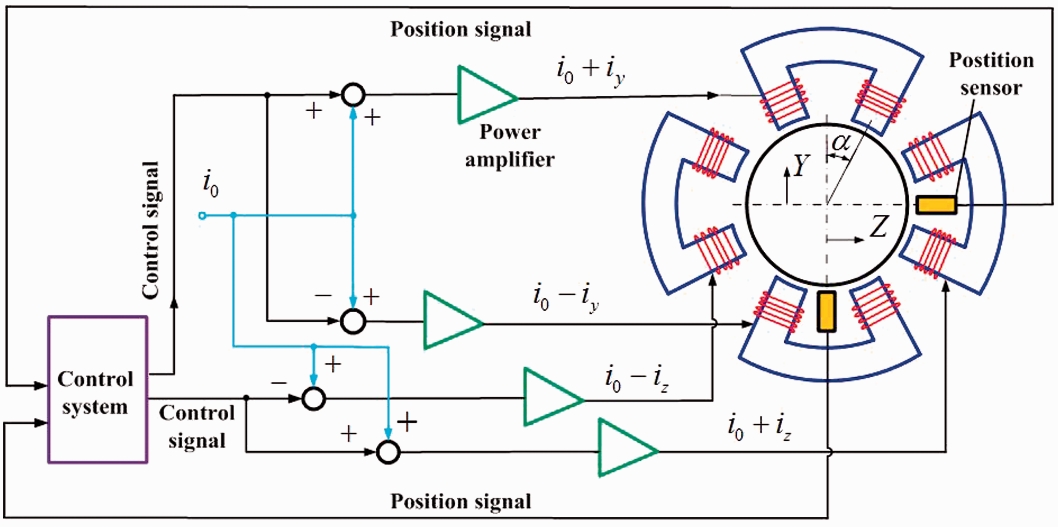
Differential driving mode of a 2-DOF electromagnetic bearing.
If the eddy current loss, flux leakage, hysteresis and saturation of the core material are neglected, the total magnetic force along the Y and Z directions can be written as
7
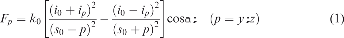
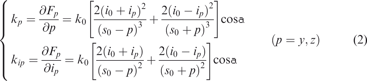
As indicated by equation (1), the displacement stiffness and the current stiffness vary with the position the rotor drifts from its reference position. The displacement stiffness is defined as the derivative of the magnetic force in equation (1) with respect to the air gap, while the current stiffness is defined as the derivative of the magnetic force in equation (1) with respect to the control current. They can be calculated by
At the equilibrium position (p = 0 and ip=0), the magnetic force can be linearized with respect to the control current and deviation of the air gap, that is

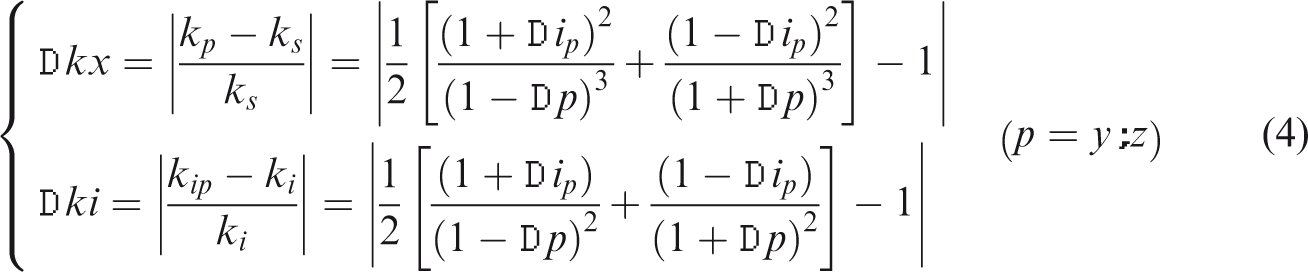
The linearization error of the displacement stiffness and the current stiffness are as follows
The linearization error of the magnetic force can be given as
Linearization errors of the displacement stiffness, the current stiffness as well as the linearized magnetic force are plotted in Figure 2. It is indicated that for the generalized current in the range of −25% ∼ +25% and for the generalized displacement in the range of −10% ∼ +10%, the relative error of the magnetic force will be no more than 5%, which is acceptable in engineering applications.
Contour plots of the linearization errors. (a) The displacement stiffness error. (b) The current stiffness error. (c) The magnetic force error.
If the magnetic forces is equivalent to spring-damping force and a PD controller is used, the equivalent stiffness Ke and equivalent damping Ce can be obtained as

Dynamic modeling of the shafting-hull coupled system
The shafting-hull system includes two elastic bodies – the shaft and the hull, and they are connected via springs, as shown in Figure 3. Parameters of the springs are listed in Table 1. In this section, the FEM 2 is used to derive the FRFs of the shaft and the hull, respectively. In the finite element models of the shaft, the shaft is modelled by beam elements and the hull by shell elements. The hull is composed of a cylindrical shell, a conic shell and an ellipsoidal shell, which are all reinforced with stiffeners. The stiffeners include longitudinal bars between the cylindrical shell and the conic shell, and ring stiffeners arranged evenly in the longitudinal direction. And the FRF synthesis method29,30 is applied to establish the dynamic model of the coupled system, which makes it convenient to explore the influence of spring stiffness.
Simplified model of the shafting-hull system.
Springs of the shafting-hull system.
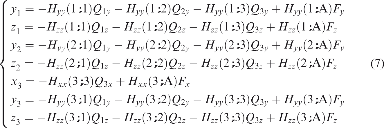
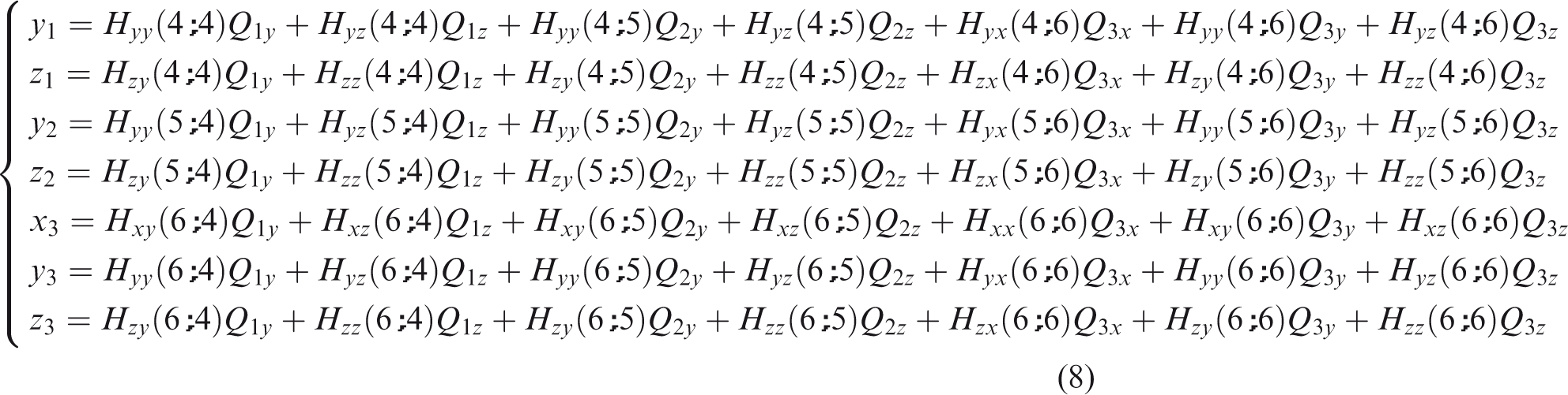
The displacements of Point 1, Point 2 and Point 3 at the shaft can be expressed as
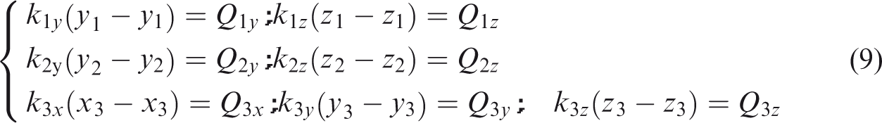
According to the continuity of displacements and the equilibrium condition of forces, there exists
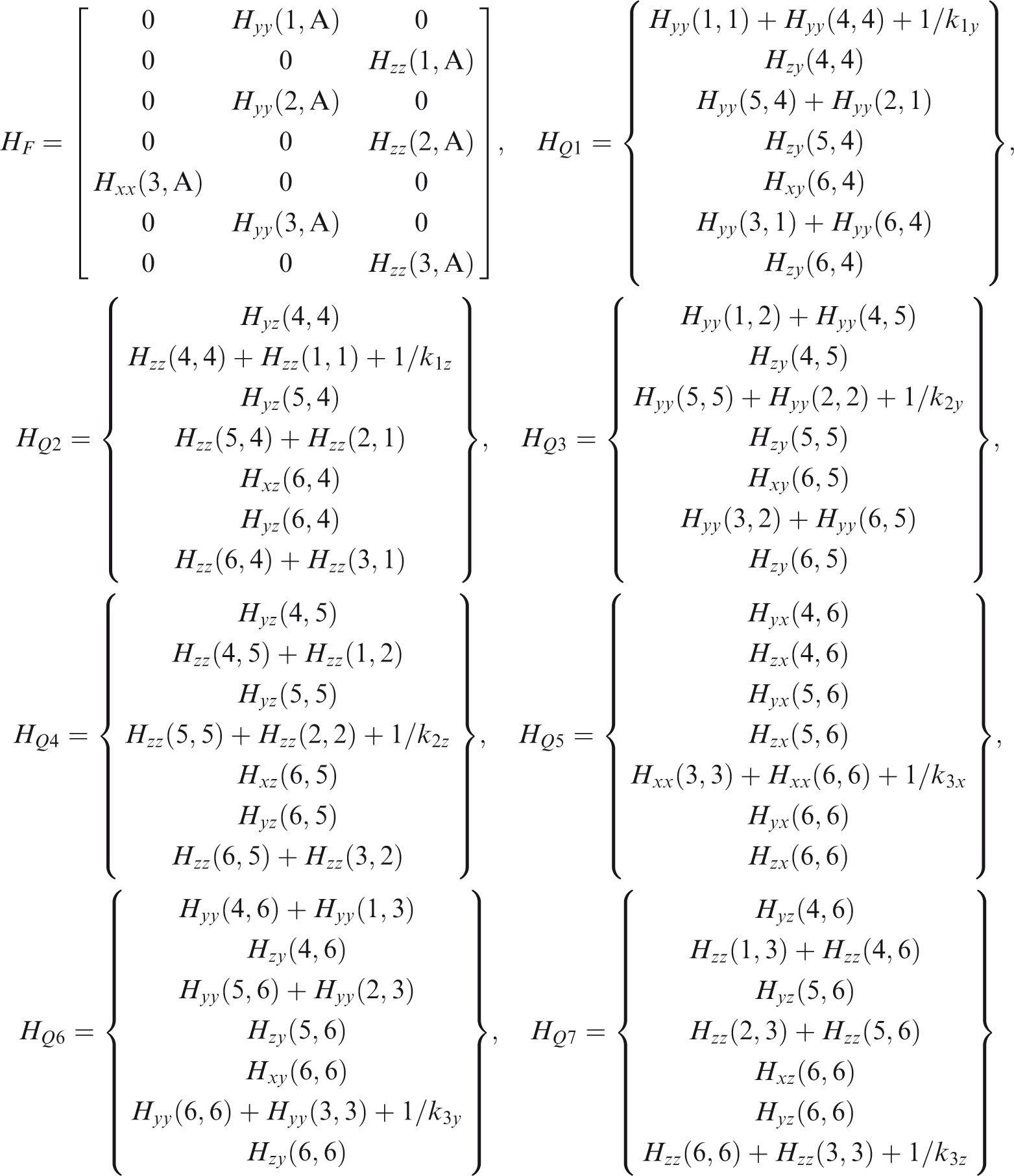
Equations (7) to (9) can be rewritten by a matrix equation

In addition, if the structural damping is considered, the stiffness k (k1 y , k1 z , k2 y , k2 z , k3 x , k3 y and k3 z ) in equation (9) can be replaced by k(1+jη), where η is the dissipation factor. When the disturbance forces are given, the interfacial forces can be calculated from equation (10) and the displacements can be calculated from equations (7) and (8). Consequently, FRFs of the system can be obtained.
Simulation results and discussions
Parameters of the EMB
The parameters of the EMB are as follows
i0 = 15 A, s0 = 1.5 mm, α = π/8, μ0 = 4π×10−7 H/m, N = 300, Aa = 324 cm2
In this section, it is assumed that the shaft is fully levitated by the EMB and the bearing stiffness is completely provided by the EMB. The equivalent stiffness can be changed by adjusting control parameters, which are listed in Table 2. Meanwhile, the structural damping of 20% is considered.
Control parameters of the EMB.
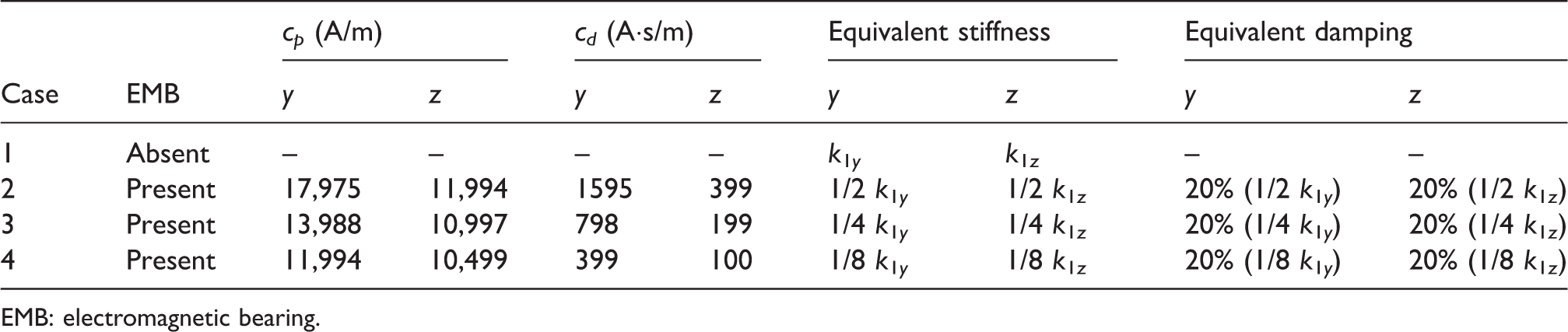
EMB: electromagnetic bearing.
In Case 1, the EMB is not activated and the shaft at the rear support is fully supported by the original rear bearing. In other cases, the shaft is entirely levitated by the EMB with different control parameters. The control parameters in Cases 2–4 are decreased gradually. As a result, the equivalent stiffness and damping of the EMB are decreased gradually as well. Analysis in this section aims to explore the effect of the control parameters on the vibration responses and acoustic radiation of the shafting-hull system, and a comparative analysis is given bellow.
Acceleration responses
To vertical excitations
The unit force in the vertical direction is exerted at Point A and the frequency range is 0.5–300 Hz with resolution of 0.5 Hz. Acceleration responses of Points 4–6 at the rear, front and thrust bearings are shown, respectively, in Figures 4 to 6. In a whole, the acceleration responses of the three bearings in the vertical direction are larger than those in the horizontal direction.
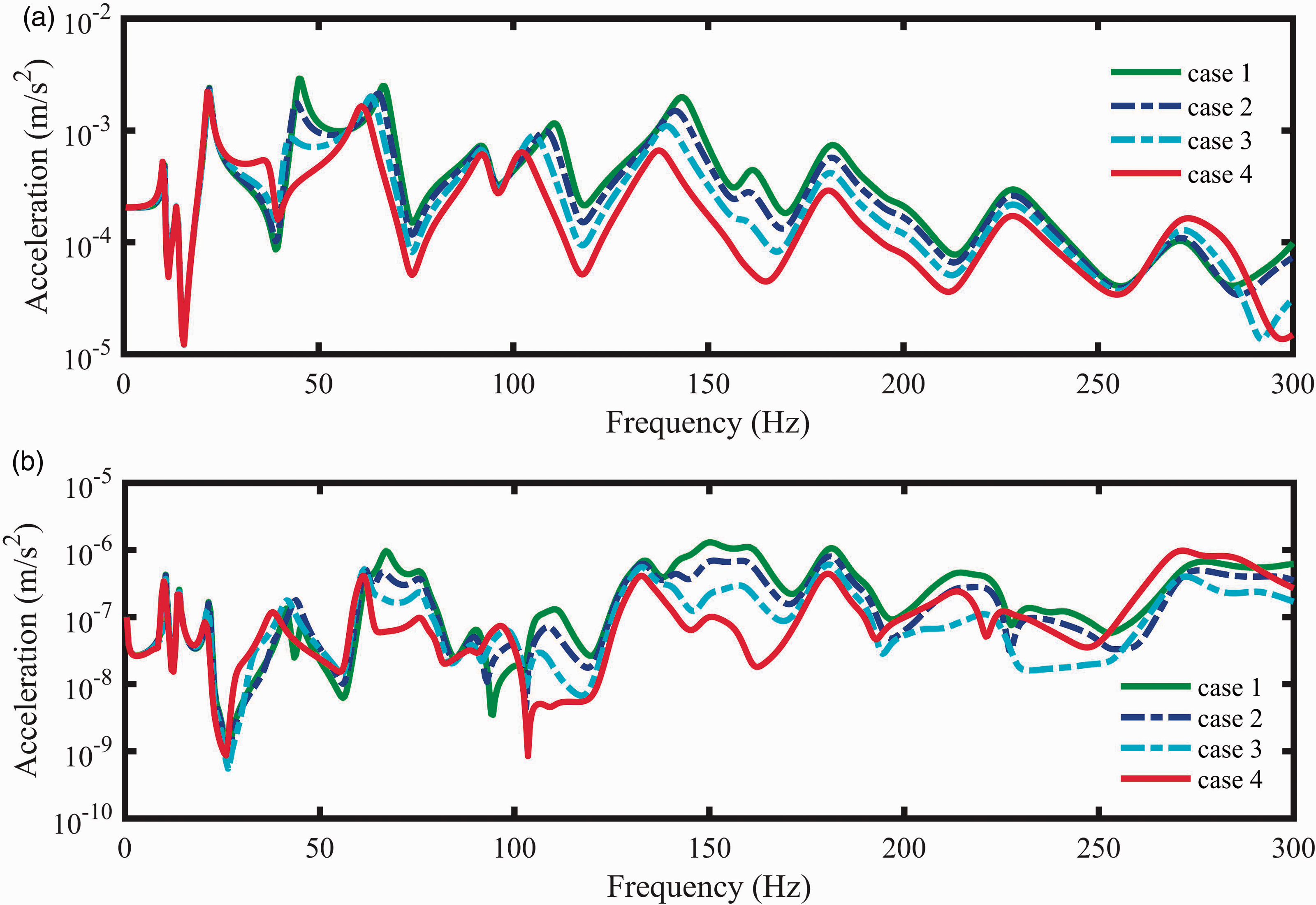
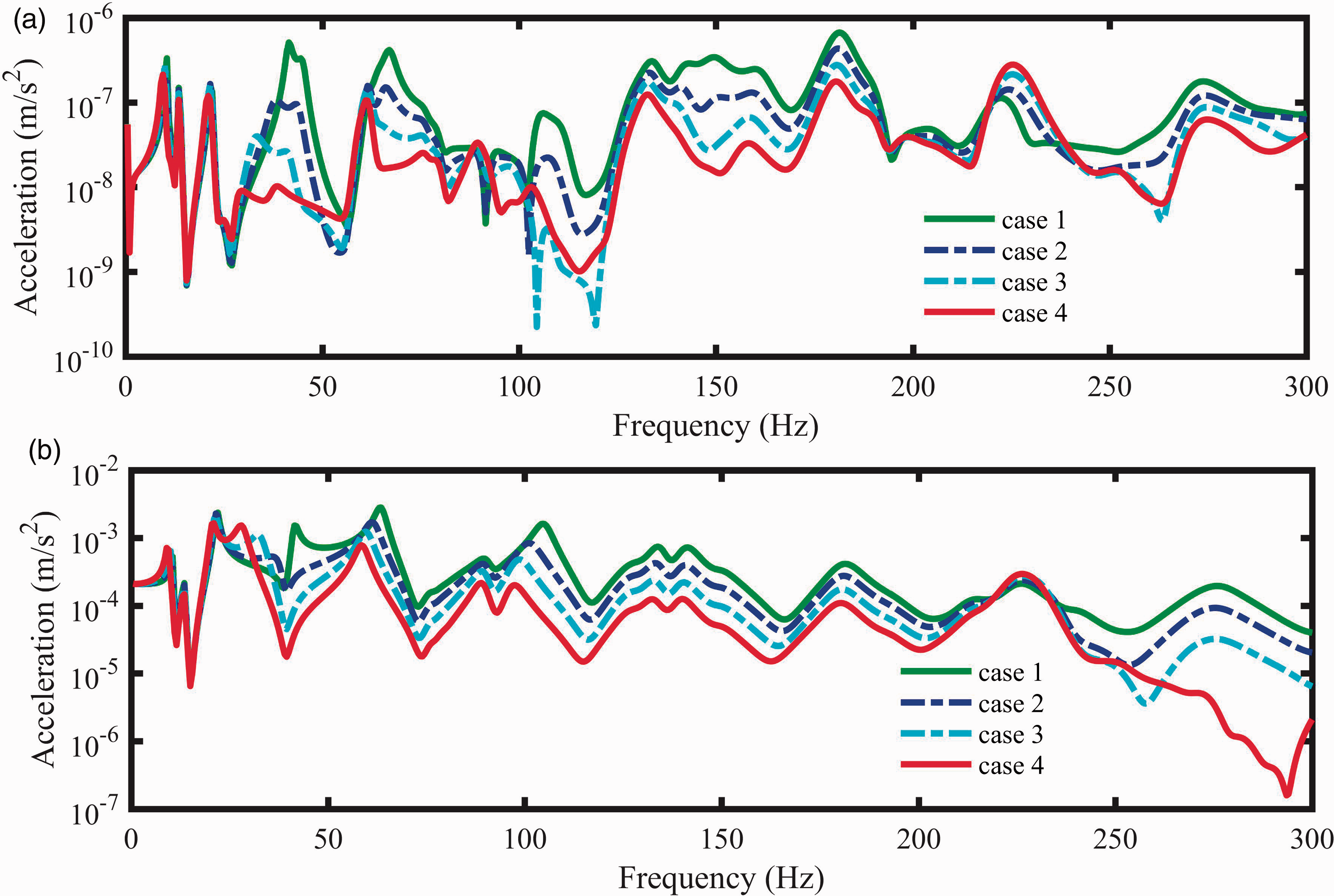
Acceleration responses of the rear bearing to the unit vertical force excitation. (a) Vertical. (b) Horizontal.
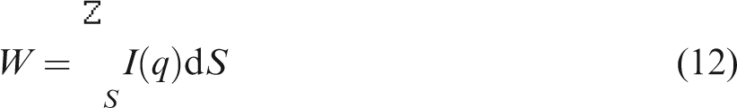
Acceleration responses of the front bearing to the unit vertical force excitation. (a) Vertical. (b) Horizontal.
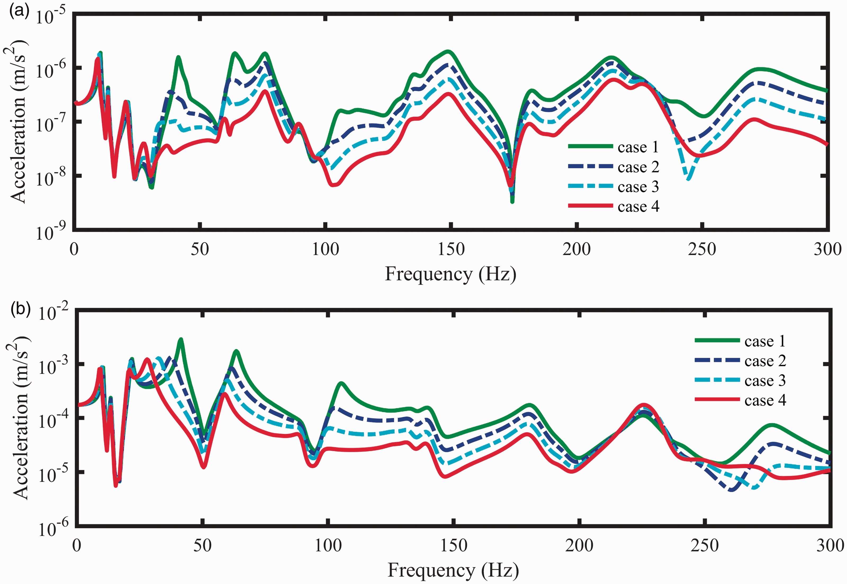
Acceleration responses of the thrust bearing to the unit vertical force excitation. (a) Vertical. (b) Horizontal.
For the vertical vibrations, in the frequency range of 0.5–25 Hz, changes in the acceleration responses at the three bearings in Cases 1–4 are limited and the resonant frequencies are shifted left slightly. In the range of 50–170 Hz, the responses are reduced and the resonant frequencies are shifted obviously in Cases 1–4. In the range of 170–260 Hz, the responses are reduced significantly. Moreover, the responses in all cases are increased slightly near 275 Hz.
For the horizontal vibrations, in the frequency range of 0.5–25 Hz, the acceleration responses keep roughly unchanged in Cases 1–4. In the range of 25–200 Hz, the responses are reduced in a whole in Cases 1–4. In the range of 200–250 Hz, the responses are decreased in Cases 1–3 but increased a little in Case 4. Moreover, the responses are increased a lot near 275 Hz so that the responses in Case 4 are much bigger than that in Cases 1–3.
To horizontal excitations
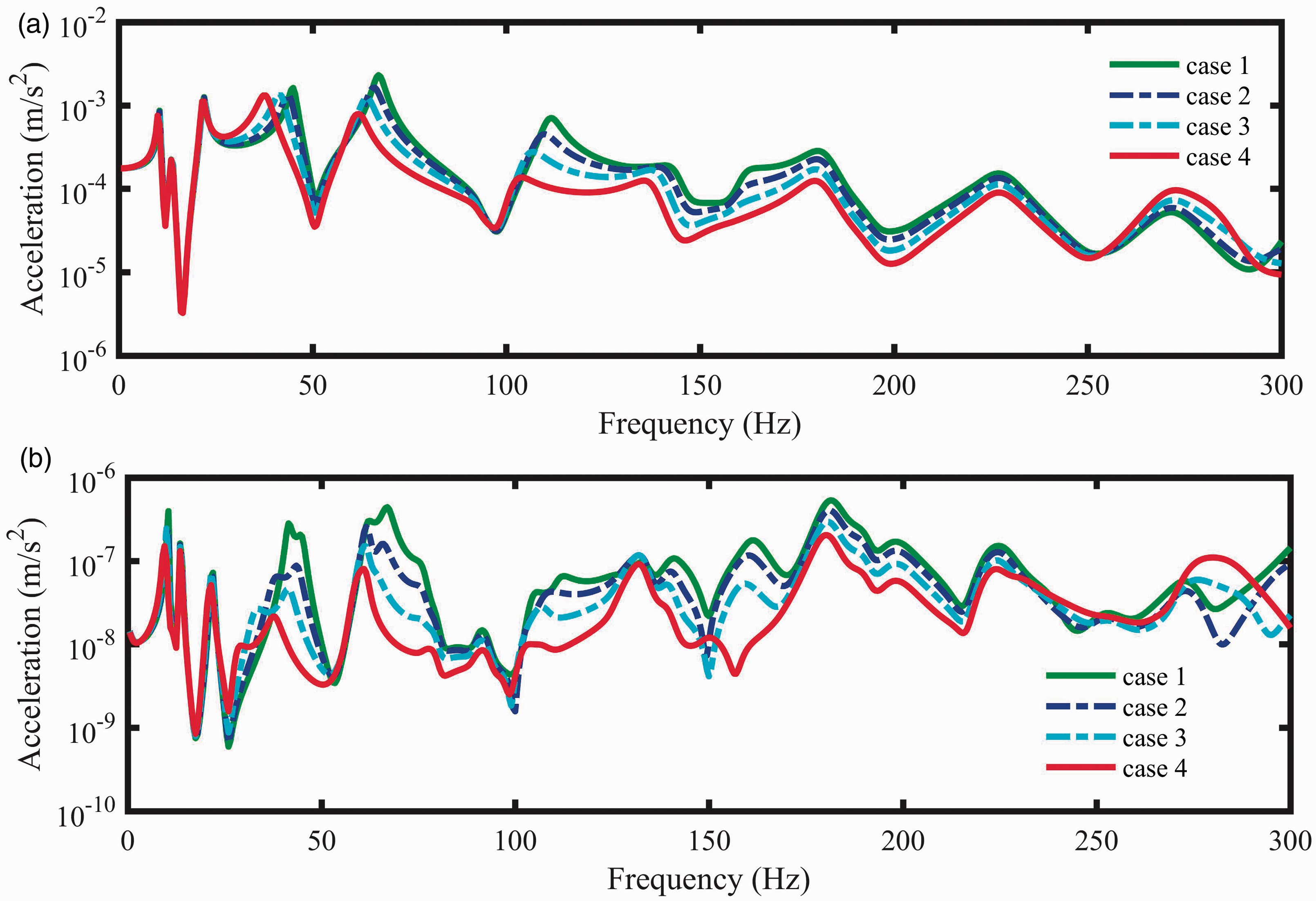
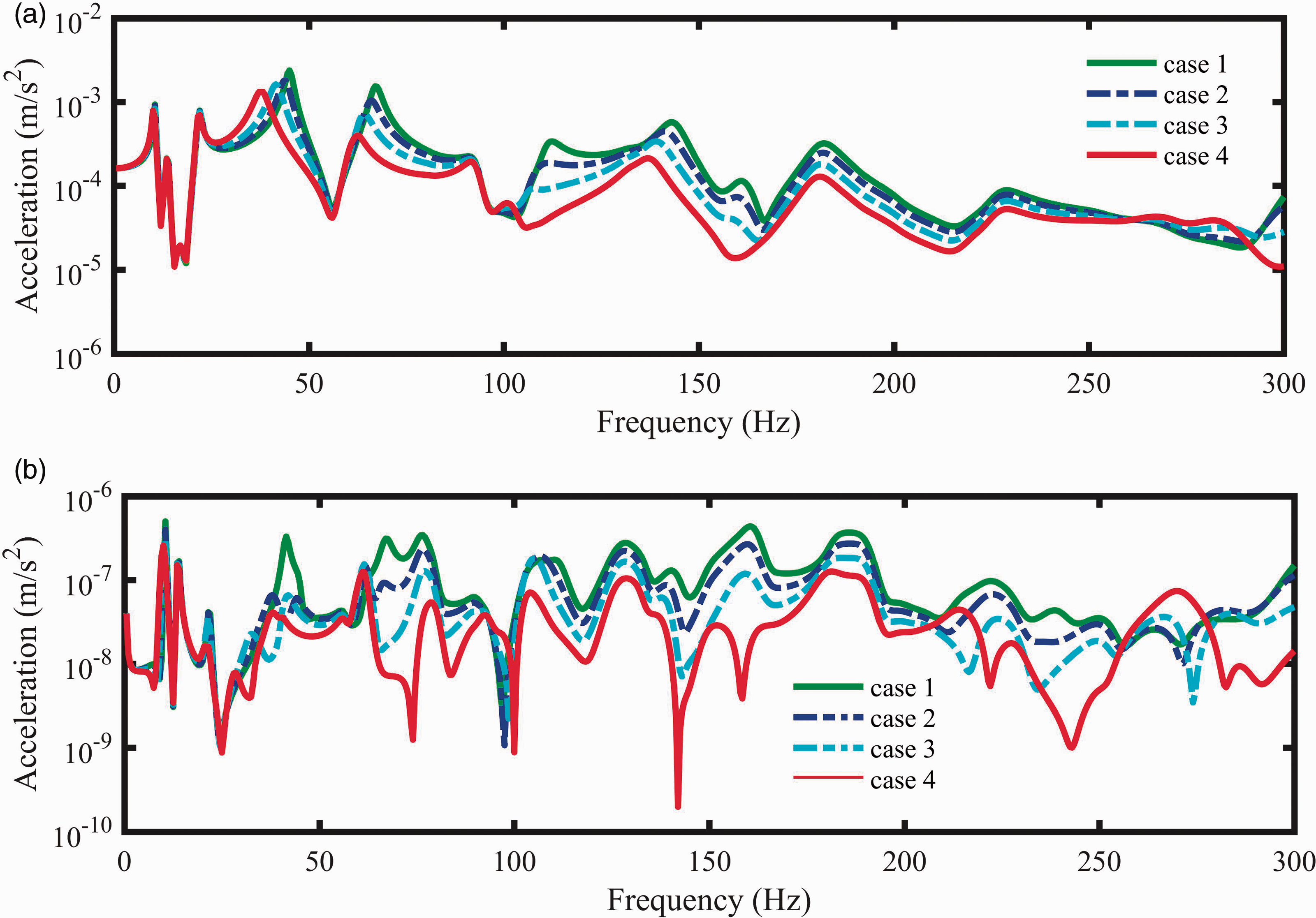
The unit force in the horizontal direction is exerted at Point A and the frequency range is 0.5–300 Hz with resolution of 0.5 Hz. Acceleration responses of Points 4–6 at the rear, front and thrust bearings are shown, respectively, in Figures 7 to 9. In the dominant direction of the horizontal direction, the acceleration responses of the three bearings are larger than those in the vertical direction.
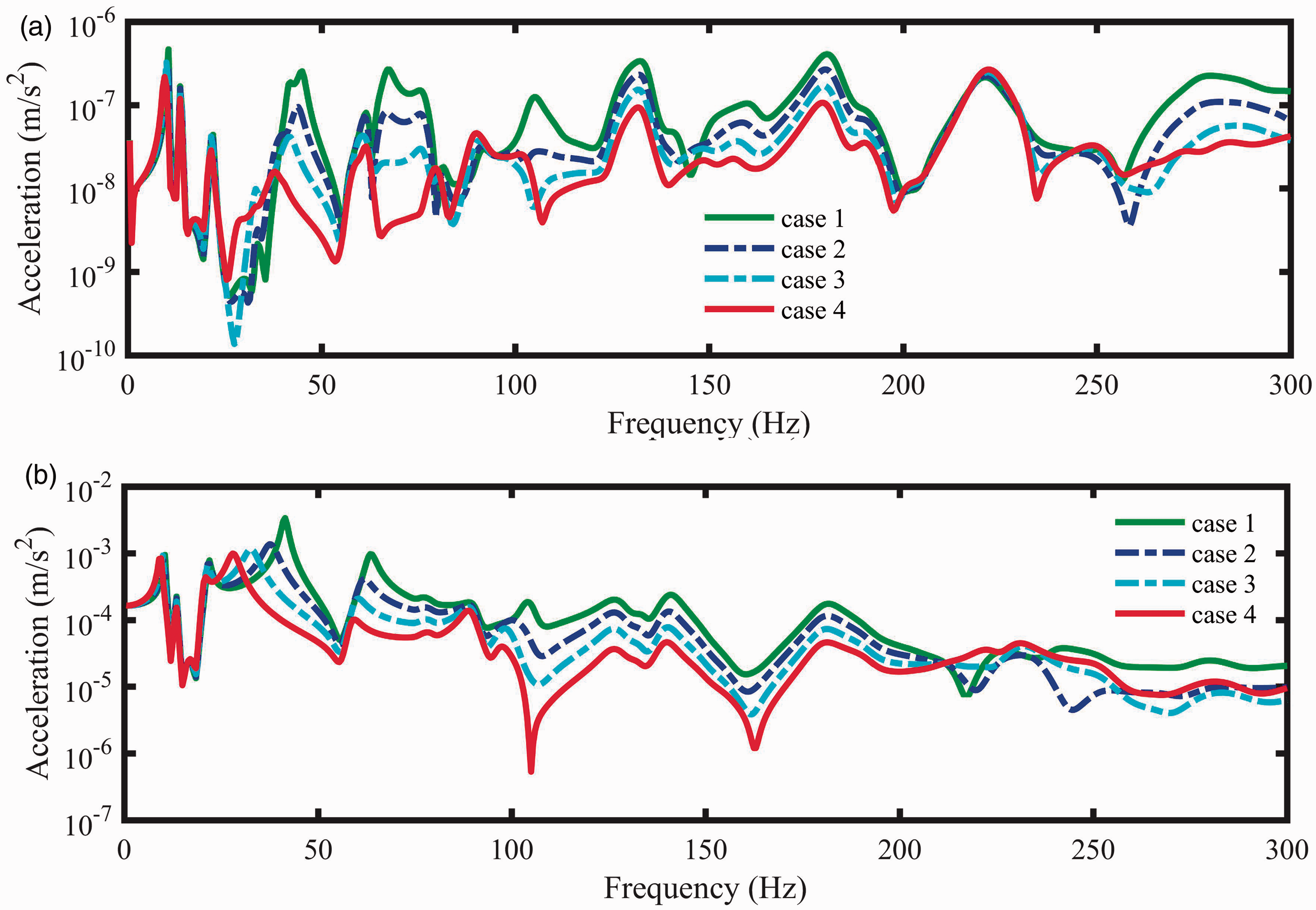
Acceleration responses of the rear bearing to the unit horizontal force excitation. (a) Vertical. (b) Horizontal.
For the horizontal vibrations, in the frequency range of 0.5–25 Hz, changes in the acceleration responses at the three bearings in Cases 1–4 are limited and the resonant frequencies are shifted left slightly. In the range of 50–200 Hz, the responses are reduced significantly and the resonant frequencies are shifted obviously in Cases 1–4. However, the responses at the three bearings are increased slightly near 226 Hz from case 1 to case 4.
For the vertical vibrations, in the frequency range of 0.5–25 Hz, the acceleration responses keep roughly unchanged in Cases 1–4. In the range of 25–200 Hz and 250–300 Hz, the responses are reduced in a whole in Cases 1–4 at the three bearings. Moreover, the responses are increased a little near 226 Hz at the rear bearing and the thrust bearing.
Acoustic radiation in air
Acoustic radiation of the shafting-hull system in air to different force excitations is calculated by using the boundary element method,
31
as long as the surface nodal velocities of the hull structure are acquired. For simplification, acoustic radiation in air is obtained. At first, the acoustic intensity on the fluid-structural interface at each node q is calculated by

Then the sound power is given by
Sound power level in decibels is calculated with the reference sound power taken to be 10−12 W. As shown in Figure 10, reduction of the sound power can be clearly observed in the range of 21.5–300 Hz in both the vertical and horizontal directions. In the range of 21.5–200 Hz, decreasing of the proportional and derivative factors can result in decreases in the sound power. Moreover, the resonant frequencies are shifted slightly to the left in the range of 21.5–170 Hz. However, the sound power is magnified slightly at 272 Hz in the vertical direction and 226 Hz in the horizontal direction. In addition, no significant difference is observed in the frequency range of 0.5–21.5 Hz except that the response peaks are reduced slightly.
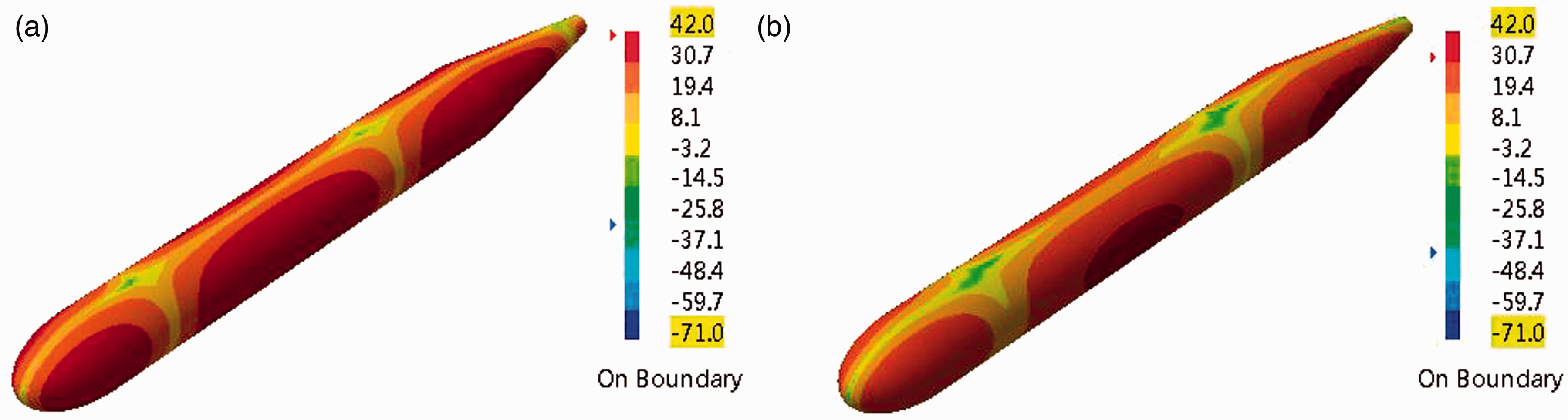
The cloud plots of acoustic pressure distribution associated with the second natural vibration of the hull to the unit force excitation are shown, respectively, in Figures 8 and 9. As can be seen, the maximum pressure amplitude in Case 1 is larger than that in Case 4 while the distributions in two cases are similar.
Acceleration responses of the front bearing to the unit horizontal force excitation. (a) Vertical. (b) Horizontal.
Acceleration responses of the thrust bearing to the unit horizontal force excitation. (a) Vertical. (b) Horizontal.
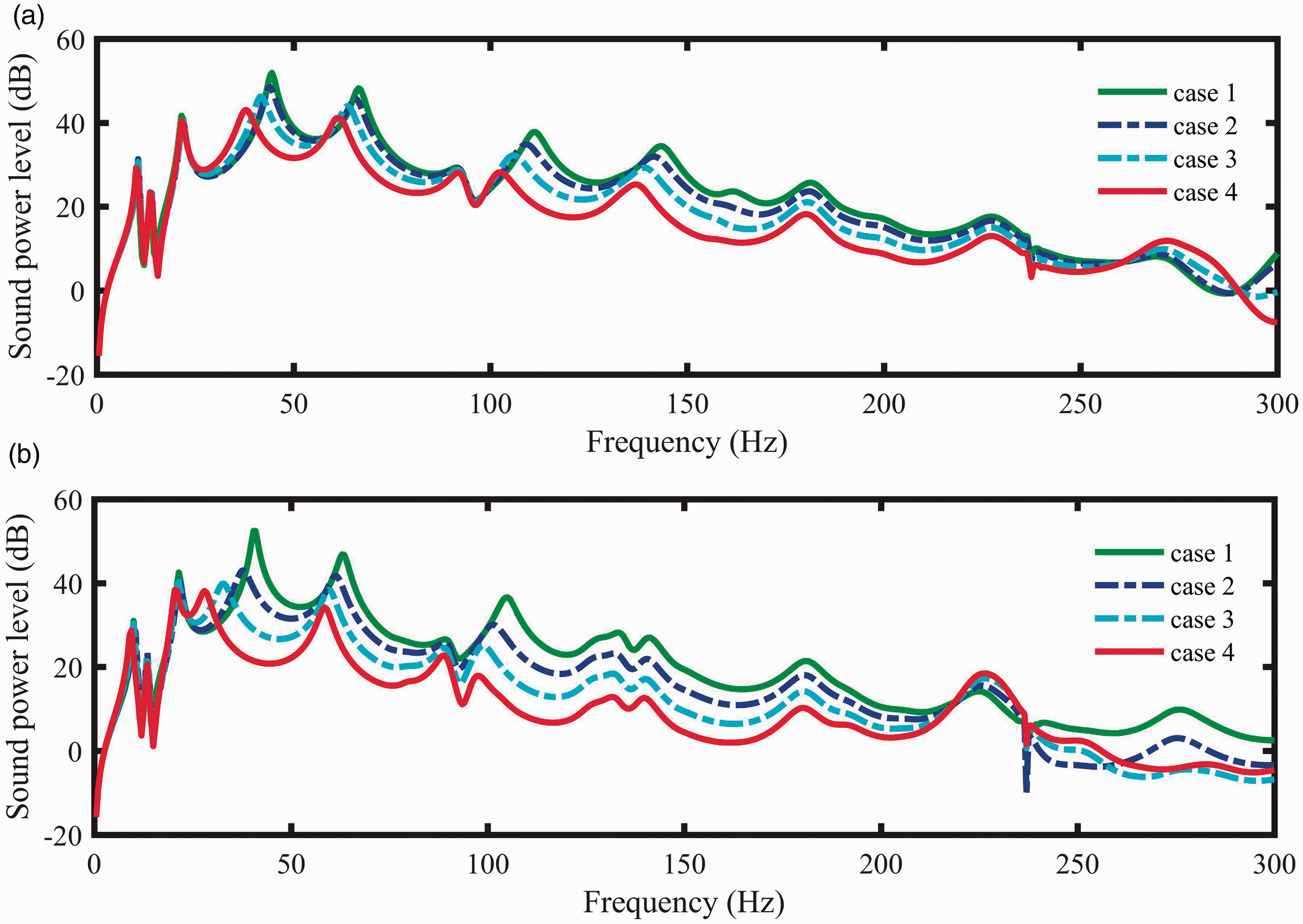
Sound power to the unit force excitation (vertical and horizontal). (a) Vertical. (b) Horizontal.
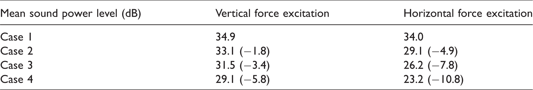
Reduction of acoustic radiation can be obviously vividly seen from Figures 11 and 12. In order to quantitate the reduction, the mean sound power levels is defined as
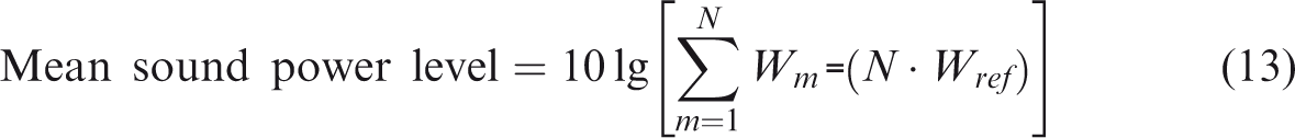
Pressure distribution (dB, RMS) at 44.5 Hz in Case 1 and 38 Hz in Case 4 to the unit vertical force excitation. (a) Case 1. (b) Case 4.
Pressure distribution (dB, RMS) at 40.5 Hz in Case 1 and 28 Hz in Case 4 to the unit horizontal force excitation. (a) Case 1. (b) Case 4.
As listed in Table 3, it can be seen that the mean sound power levels to the unit vertical force excitation are reduced, respectively, by about 1.8, 3.4 and 5.8 dB in Cases 2–4 as compared to the original bearing support without the EMB, while the mean sound power levels to the unit horizontal force excitation are reduced, respectively, by about 4.9, 7.8 and 10.8 dB. Therefore, it can be concluded that the acoustic radiation can be reduced adjusting the control parameters.
Comparison of the mean sound power levels (dB, the reference sound power is 10−12 W).
Conclusions
Theoretical investigation on the vibration transmission control of a shafting-hull system with EMBs is presented. The frequency response synthesis method is employed to establish a dynamic model of the shafting-hull system with EMBs, and based on this model, the influence of control parameters on vibration and acoustic radiation of the shaft-hull system is explored. When the shaft at the rear bearing is fully supported by the EMB, the supporting stiffness is entirely determined by the EMB and the control parameters. By changing the control parameters, different equivalent stiffness and damping can be obtained and consequently the transmission characteristics are changed. Simulation results indicate that acceleration responses at the three bearings can be controlled and reduction of the acoustic radiation of the shaft-hull system can be achieved.
Nevertheless, the rear bearing is usually a water-lubricated rubber bearing. When the shaft at the rear support is fully levitated by an EMB, no friction will exist in the bearing and acoustic radiation can be further reduced. This will be investigated further in the future. In addition, appropriate control schemes for EMBs need to be developed and experimental validation is necessary.
Footnotes
Declaration of conflicting interests
The author(s) declared no potential conflicts of interest with respect to the research, authorship, and/or publication of this article.
Funding
The author(s) disclosed receipt of the followings financial support for the research, authorship, and/or publication of this article: This work was supported by the National Natural Science Foundation of China (Grant No. 11672180) and the Shanghai Rising-Star Program (Grant No. 18QA1402000).