
Abstract
Multi-electrification is an important development direction of aero-engine. Spindle direct-drive startup generator (SDSG) is the key technology, and it introduces electromagnetic excitations to aero-engine dual-rotor system (DRS). With the pursuit of high efficiency, clearances between components become smaller and smaller and it makes the rub-impact more easily to happen. Because of the SDSG and small seal clearance between rotors, dynamic characteristics of DRS considering electromagnetic excitation and rub-impact deserve attention. This paper researches the dynamic characteristics of DRS coupling electromagnetic excitation and inter-shaft rub-impact (ISRI) at different rotation speeds, initial static eccentricities, and mass eccentricities. The dynamic model of spindle direct-drive DRS with electromagnetic excitation and ISRI is established. Results show that electromagnetic excitation increases the speed range of intermittent rub-impact in DRS by 141% and reduces the speed range of continuous rub-impact in DRS by 21%. At certain rotation speeds, specific fraction multiple frequencies (e.g., A+B→f l , C+D→f l , E+F→f l ) conforming to a particular rule occur in rotor system. 0.5f h leads to the subharmonic resonance when initial static eccentricity falls within a certain range. The mass eccentricity of magnetic steel increases the intermittent rub-impact threshold in DRS by 149%, while reducing the continuous rub-impact tolerance by only 5%. This indicates that electromagnetic excitation can suppress the vibration of DRS during ISRI. The researches can offer guidance for the vibration identification and control of aero-engine spindle direct-drive DRS.
Keywords
Introduction
Electromagnetic excitation mainly includes UMP and electromagnetic torque, which are mainly caused by uneven air-gap distribution within the SDSG due to machining accuracy, assembly errors and component vibration. 2 Some scholars have carried out UMP studies assuming that stator and rotor axes of motor are parallel. In this situation, air-gap eccentricities are divided into dynamic and static eccentricities. Dynamic eccentricity means that stator and rotor are concentric before the motor operation, the stator and rotor are not concentric due to external excitation, and the rotor takes geometric central axis of stator as rotation axis. Static eccentricity refers to a condition where rotor axis deviates from stator axis before the motor is operated and rotor rotates around its own geometric center. The Fourier series was used by Belmans et al.3,4 to derive the air-gap permeability, and the motor magnetomotive force was adjusted by them to obtain a more accurate expression of UMP. Peters et al. 5 investigated the effect of magnetic saturation of magnetic motive force on UMP of the eccentric hydrogenerator by ignoring the magnetic flux leakage and assuming that the magnetic flux is constant along the magnetic circuit. In addition, Alam 6 and Xu 7 consider the influence of magnetic saturation effect on magnetomotive force when establishing the electromagnetic excitation model. Gou et al. 8 used Fourier series and Maxwell stress to deduce the analytical expressions of UMP and analyzed the influences of dynamic eccentricity, static eccentricity, and polar pairs on UMP. On the basis of Gou, Perpers 9 proposed the nonlinear analytical formula of UMP with consideration of eccentricity and magnetic saturation effect. Some scholars considered that rotor axis is not parallel to stator axis in actual operation. Under these conditions, the axial air-gap of motor is uneven and there is an angle between rotor and stator axes, which is defined as inclined eccentricity. The coexistence of dynamic eccentricity, static eccentricity and inclined eccentricity of motor is called comprehensive eccentricity. Inclined eccentricity results in uneven axial UMP and the generation of electromagnetic torque. 10 Akiyama 11 proposed a rotor inclined eccentricity model based on engineering practice. Xu et al. 12 derived the integral expressions of UMP and electromagnetic torque under comprehensive eccentricity and conducted research into how electromagnetic excitation influences the dynamic behavior of Jeffcott rotor. In addition, many scholars have researched the influences of electromagnetic excitation on rotating machinery rotor systems, such as hydraulic generator, turbine generator, and motorized spindle.13–26
The HPR and LPR are generally supported independently in many DRS. 27 The ISRI is rotor-rotor rubbing and provides a new energy transfer pathway. However, most of studies on aero-engine DRS rubbing are focused on rotor-static rubbing.28–32 In the previous researches, a few scholars paid attention to the effect of ISRI on DRS. Chen 33 established a dynamic equation of DRS with ISRI and found that the quasi-periodic and multi-periodic phenomena appear in the DRS. Yu 34 developed a high-precision finite element model to investigate the ISRI dynamics of DRS and found that the rubbing can excite self-excited vibration in DRS. Yu 35 compared the nonlinear dynamic behavior of ISRI between co-rotating and counter-rotating DRS and found that co-rotating DRS mainly excites forward vortex modes of rotor, the counter-rotating DRS mainly excites the reverse vortex modes of rotor. Wu et al. 36 used the reduced-order model to establish the dynamic equation of dual-rotor-support-casing system and revealed its dynamic characteristics with ISRI.
At present, significant number of research achievements have been obtained in study of the influence of rub-impact or electromagnetic excitation on rotating machinery rotor systems Because of SDSG and small seal clearance, the influences of electromagnetic excitation coupled with ISRI on the dynamic characteristics of DRS have gradually aroused the interests of scholars. However, there are relatively few scholars studied the vibration responses of rotating machinery with UMP and rubbing. Zhang et al. 20 found that with change of the excitation current, quasi-periodic motion and chaotic alternating motion appear in the rotor system of hydraulic generator with UMP and rubbing. Huang, 37 Zhang,38,39 et al. also carried out the studies of dynamic behaviors of hydraulic generator with UMP and rubbing. In these studies, the rubbing force and UMP are applied to the same node, and the type of rubbing is rotor-static rubbing. The aero-engine spindle direct-drive DRS has characteristics of long span and multi-disc cantilever. The rubbing may occur in the labyrinth seal position, which is not in the same position as the electromagnetic excitation. And the ISRI is rotor-rotor rubbing. There is no report on the research of dynamic characteristics of DRS coupling electromagnetic excitation and ISRI.
This study investigates the coupled dynamics of electromagnetic excitation and ISRI in a certain type of aero-engine spindle direct-drive DRS. The results demonstrate that the electromagnetic excitation lengthens the rotational speed range where intermittent rub-impact occurs and leads to ISRI even in the non-critical speed range, induces the subharmonic resonance in some special frequencies, and makes the mass eccentricity margin for the occurrence of intermittent rub-impact increase. The research provides support for stable operation of more electric aero-engines with the same structure.
The organization of this paper is as follows: Firstly, the background and the research status of the study are introduced in Section 1. Secondly, the dynamic model of spindle direct-drive DRS, including finite element model and exciting force model, is established in Section 2. And the effectiveness of electromagnetic excitation model and finite element modelling approach are also verified by experimental method in Section 2. Thirdly, the inherent characteristics of spindle direct-drive DRS with ISRI are analyzed in Section 3. And the dynamic characteristics of DRS coupling electromagnetic excitation and ISRI at different rotation speeds, initial static eccentricities, and mass eccentricities of magnetic steel are discussed respectively in Section 3. Finally, the conclusions are offered in Section 4.
Dynamic model of spindle direct-drive DRS
Finite element model of spindle direct-drive DRS
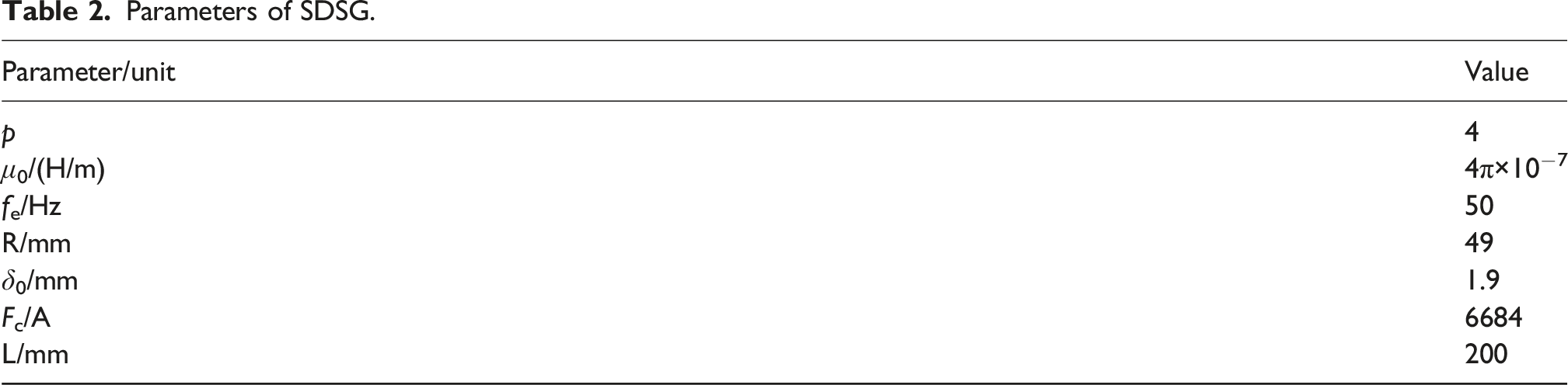
The DRS conducted in this paper has classic structures including HPR, LPR, and support system, which structural diagram is shown in Figure 1. The HPR and LPR are both supported by two elastic supports, there is no inter-shaft bearing between rotors, which means HPR and LPR operating independently under ideal working condition. And the HPR and LPR are supported by 0-2-0 and 1-0-1 respectively. The finite element of high pressure shaft and low pressure shaft are established by Timoshenko beam element. The high pressure compressor and turbine (Disk1-Disk2), SDSG magnetic steel (Disk3), and low pressure compressor and turbine (Disk4-Disk5) are simplified as lumped masses. And they are treated as rigid. The support system is simplified as linear spring and elastic damping. The parameters of shaft elements, Disk1–Disk5, and support elements are shown in Appendix A. Structure diagram of aero-engine.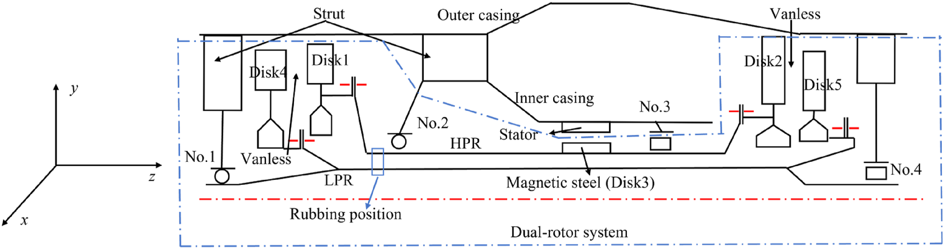
The shaft element consists of two nodes, each has five degrees of freedom, namely translational degrees of freedom in the x and y directions and rotational degrees of freedom around the x, y, and z axes. The vibration along axial direction of DRS is disregarded. The element displacement vector can be expressed as:
According to the Lagrange equation, the DRS dynamic equation is established.
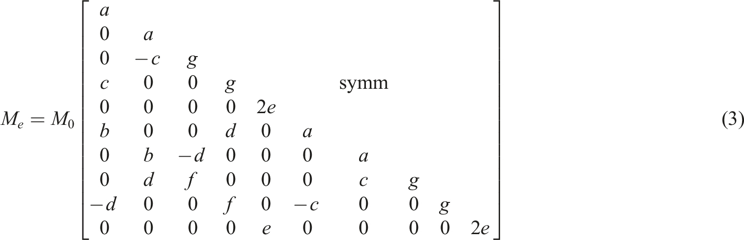
The M
e
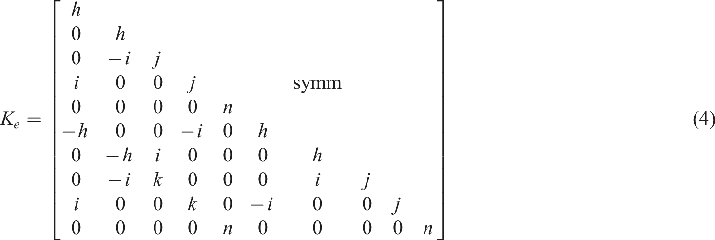
, K
e
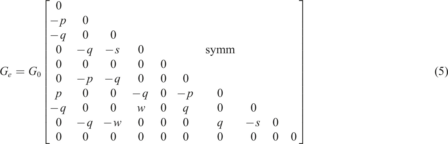
, and G
e
of shaft element are shown as equations (3)–(5). The parameters in equations (3)–(5) are given in Appendix B.
40
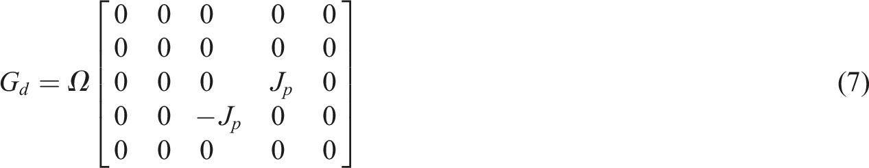
The M
d
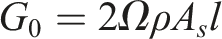
and G
d
of disk element are shown in equations (6)–(7). The relationship between polar inertial moment and diametric inertial moment is given by 
In this paper, Rayleigh damping matrix is given by equations (8)–(9).
41


In this paper, the bearing support is simplified to a linear spring damping model, and only the translational stiffness and damping of the bearing are considered. By taking the translational elastic potential energy of the bearing into the Lagrange equation, the element stiffness matrix K
s
and damping matrix C
s
of the support can be obtained as equations (10)–(11).
Exciting force model
Electromagnetic excitation model
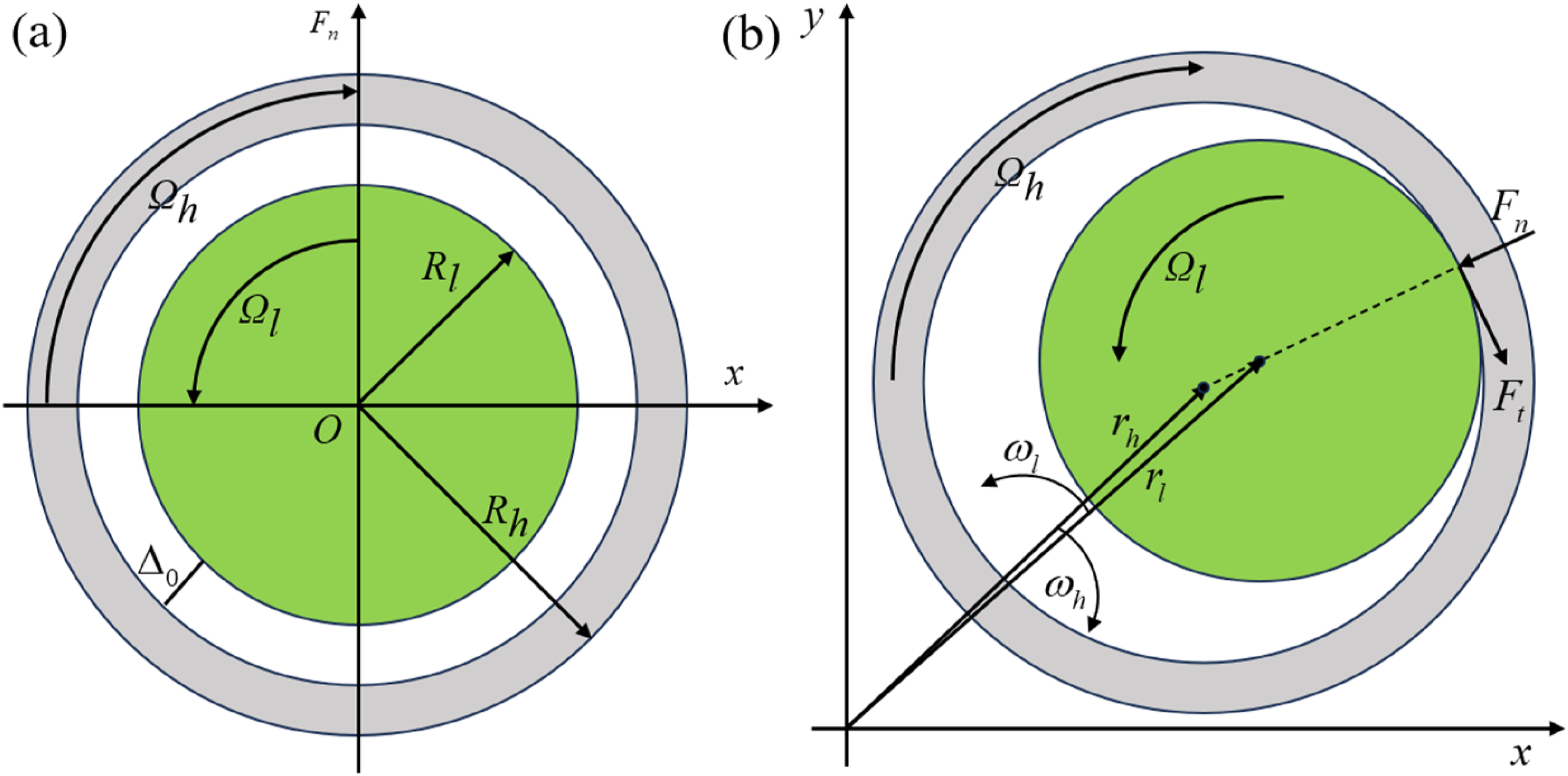
In engineering practice, manufacturing errors, bearing wear and other factors can create the comprehensive eccentricity in DRS, which results in UMP and electromagnetic torque. In particular, comprehensive eccentricity reaches its maximum when HPR passes through critical speed. In this section, the UMP and electromagnetic torque model are established with comprehensive eccentricity. The air-gap of a certain section of SDSG with comprehensive eccentricity is shown in Figure 2. Arbitrary cross-sectional air-gap of SDSG rotor.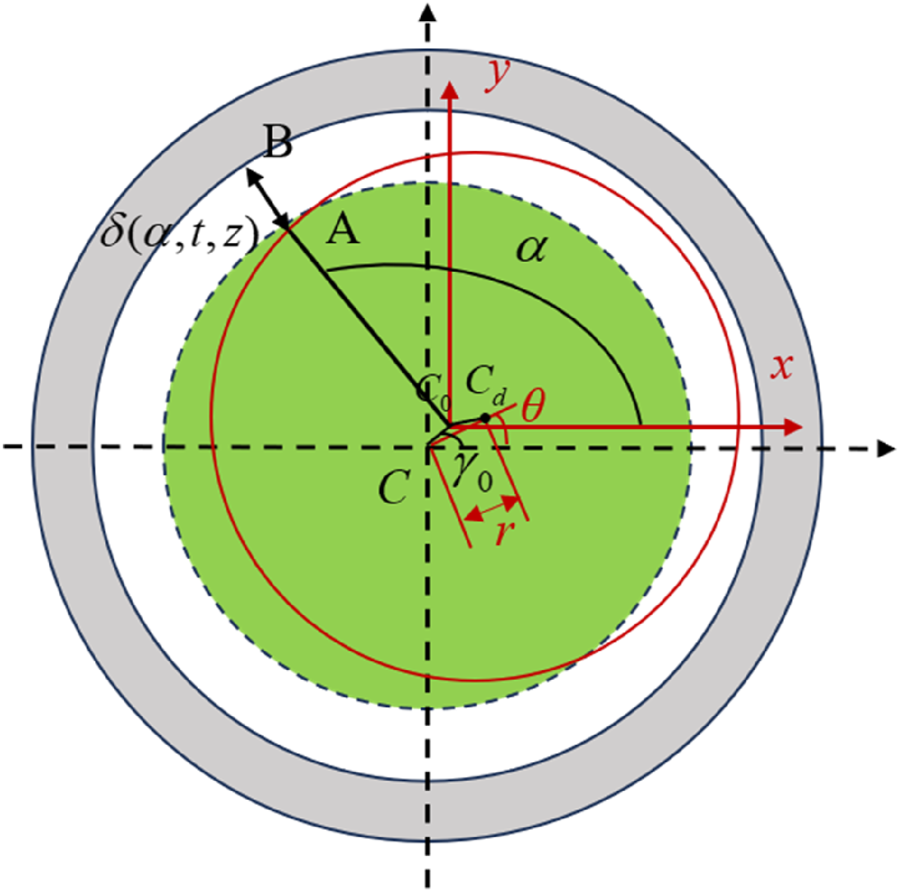
During the derivation, the following simplifications are made:
In this paper, the inclined eccentricity is expressed by displacement parameter and angle parameter. x and y are displacement responses. θ
x
and θ
y
are angle responses. x0 and y0 are initial static displacement eccentricities. And θx0 and θy0 are initial static angle eccentricities. The motion state of DRS are described by these parameters. The initial static eccentricity of SDSG rotor can be expressed as:
The derivation of the position relationship between SDSG rotor and stator is shown in Appendix C. According to the Appendix C, γ is the angle between axis of HPR and stator of SDSG. Considering the θ
x
, θ
y
, θx0, and θy0, γ is shown in equation (13).
The comprehensive eccentricity expression of DRS is shown in equation (14):
The comprehensive eccentricity direction angle expression of aero-engine spindle direct-drive DRS is shown in equation (15):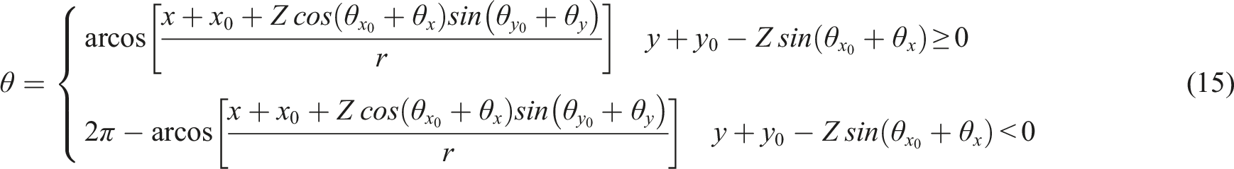

The axial position of cross-section is shown in equation (17):
Based on motor principle, the fundamental magnetic motive force (MMF) is shown in equations (18)–(21)
50
:


The air-gap permeance of SDSG can be shown in equation (18)51,52:
The magnetic flux density within motor is shown in equation (23)
53
:
Due to infinite magnetic permeability of rotor core, the tangential component can be ignored.23,24 The Maxwell stress is shown in equation (24):
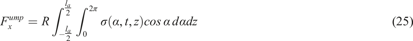
By integrating the horizontal and vertical components of Maxwell stress on rotor surface, the UMP of infinitesimal elements in the x-direction and y-direction can be obtained. The UMP of rotor can be calculated by integrating infinitesimal elements along the z-direction, which are shown in equations (25)–(26)
12
:

The unbalanced electromagnetic force of the studied infinitesimal element exerts a non-zero moment arm on the inclined rotor in general situations. Therefore, the electromagnetic torque on dynamic characteristics of DRS is not negligible. Electromagnetic torque are shown in equations (28)–(29)
12
:

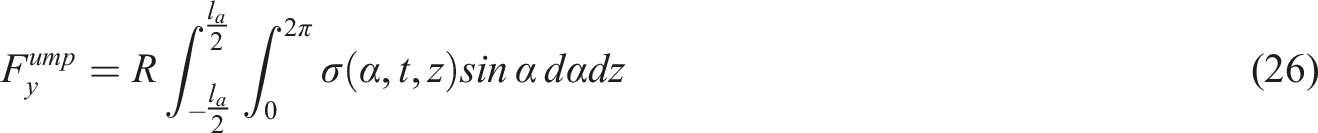
The SDSG experimental system includes DC power supply, drag equipment, control system, motor, and vibration testing and acquisition system, etc. The schematic diagram of vibration testing and acquisition in this paper is shown in Figure 3. The experimental SDSG consists of rotor, stator and casing, etc. The vibration responses of SDSG are obtained by acceleration sensors arranged on the outer casing. The acceleration sensors are placed at the corresponding positions of the two bearings of the SDSG. The sampling frequency during the experiment is 10.24 KHz. The vibration measurement system of SDSG. (a) Schematic diagram, (b) Photograph of the physical object.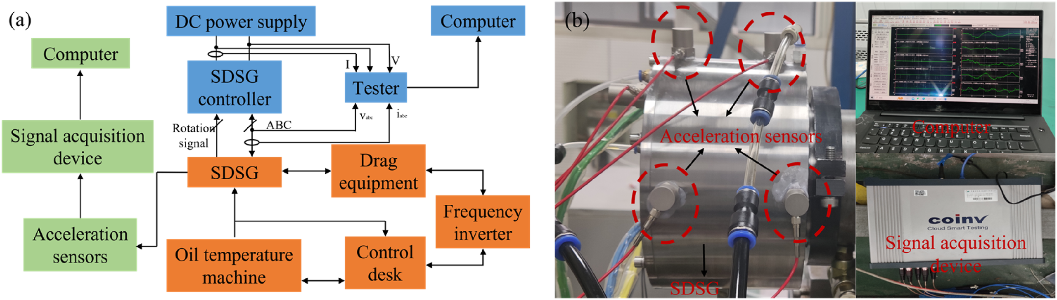
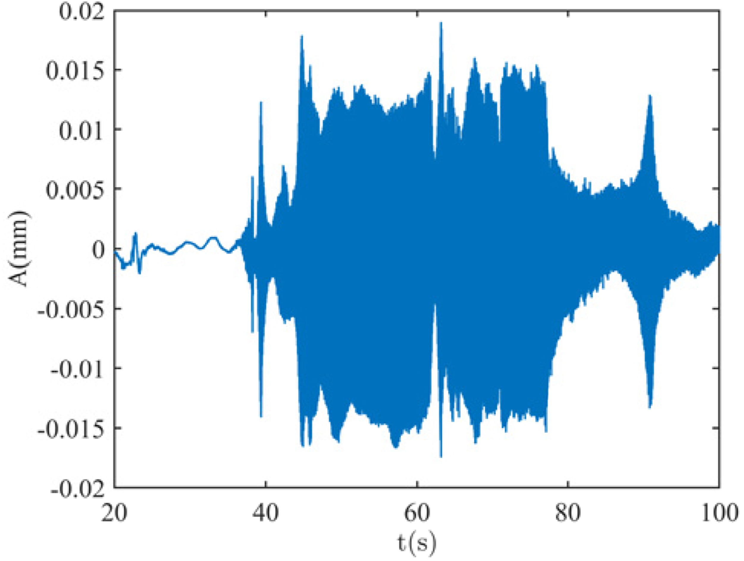
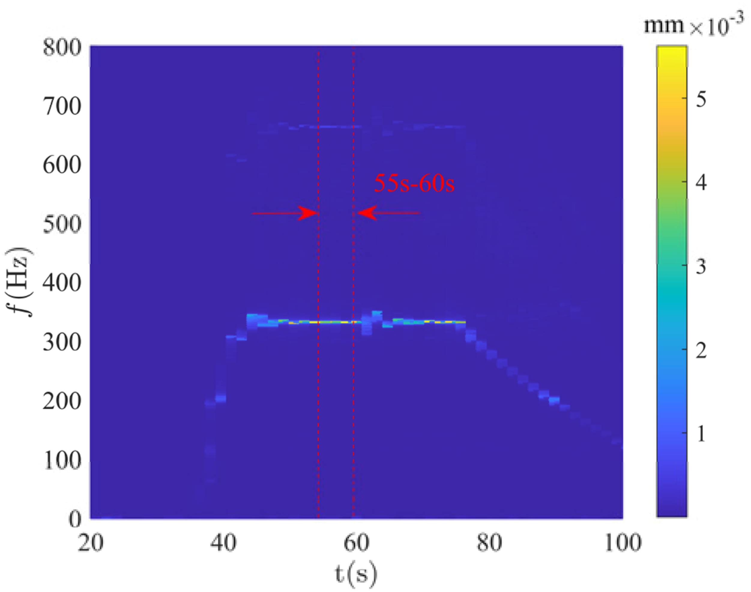
In this study, the vibration response of SDSG was measured during its starting performance tests. During the test, the SDSG was ramped up from 0 rpm to 20,000 rpm under no load. The speed versus time curve is shown in Figure 4. And the amplitude of vibration of SDSG is shown in Figure 5. After a period of stable operation, torque was applied to conduct the SDSG starting characteristic test. This paper focuses on the vibration response of the SDSG after it stabilizes at 20,000 rpm, as shown in Figure 6. It can be observed that the SDSG begins to accelerate around 35 s, reaches 20,000 rpm at 45 s, and operates steadily until 80 s. Therefore, the vibration response in the time period [55 s-60 s] was selected for comparison with the numerically calculated results, as shown in Figures 7–8. In order to better illustrate the calculation results, logarithmic coordinates are used in Figure 7. Rotation speed of SDSG. Time-domain waveform. Vibration response of SDSG. Vibration response of SDSG rotor system. (a) Numerical result, (b) Experimental data. Horizontal spectrums of SDSG rotor system. (a) Numerical result, (b) Experimental data.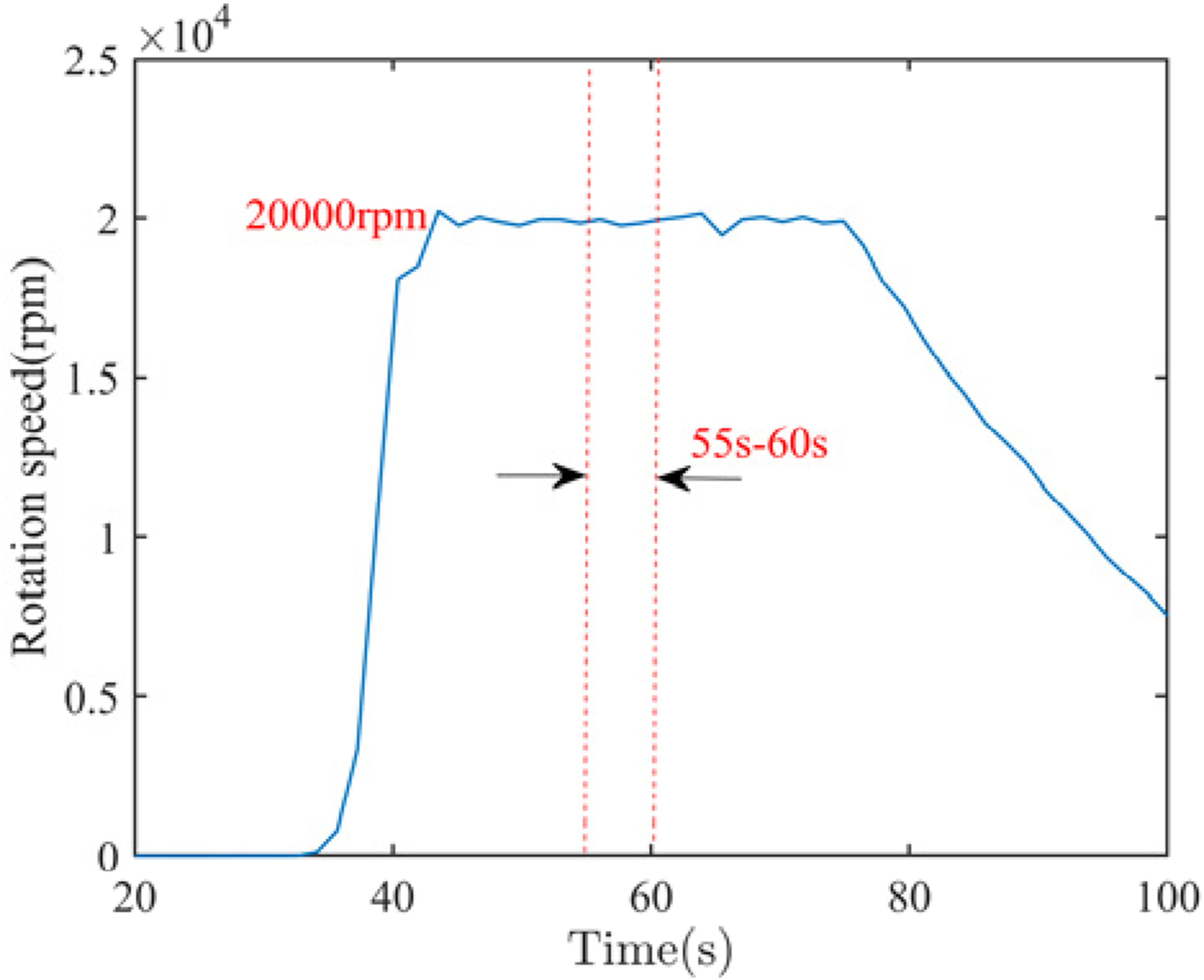
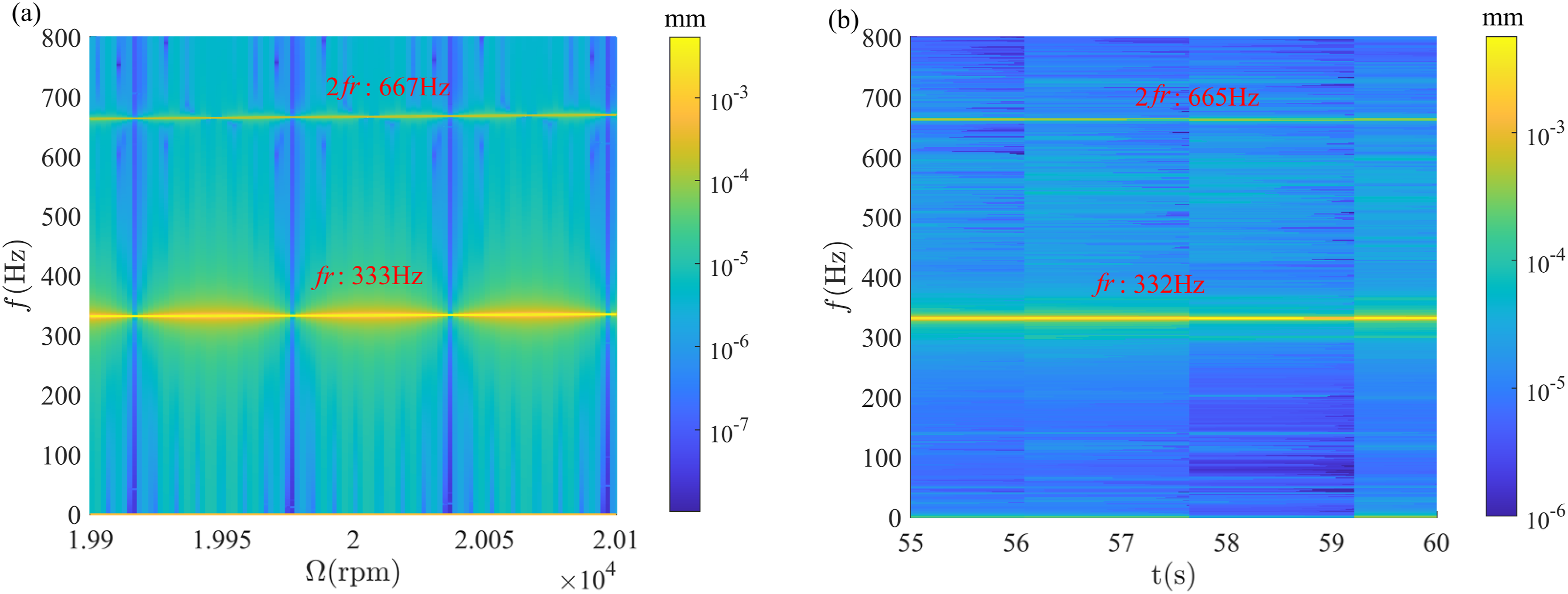
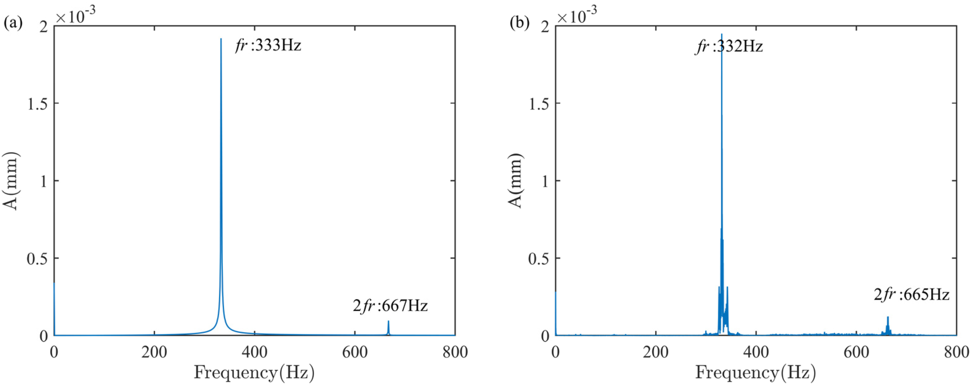
Obviously, the fundamental rotation frequencies f r and its harmonic 2f r , appear in both numerical and experimental results. The amplitude and vibration period of the numerical results are approximately similar to those of the experimental results. However, some differences between the experimental and simulation results are noted, primarily in the frequency domain. These differences are manifested by the presence of low harmonic frequencies around the fundamental frequency in the experimental data. The primary cause of this phenomenon is attributed to electromagnetic interference and other factors encountered during the actual operation of the SDSG. These does not affect primary frequencies such as the fundamental frequency and double fundamental frequency. This indicates that these errors are acceptable. Therefore, the electromagnetic excitation model and modelling method proposed in this paper are effective.
ISRI force model
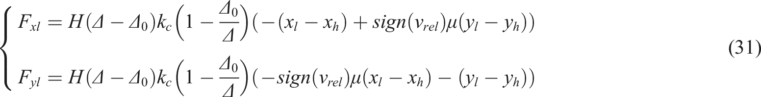
A mechanical model of ISRI is established in Figure 9. The contact process of ISRI is simplified to friction between two circles. Δ is center distance of HPR and LPR. Mechanical model of ISRI. (a) Undeflected rotors; (b) Deflected rotors.


Unbalanced mass force model
The unbalanced mass force is brought to DRS by mass eccentricity of rigid disk as shown in equations (34)–(36):


Dynamic characteristics of spindle direct-drive DRS
In this section, the inherent characteristics of spindle direct-drive DRS are analyzed. And the dynamic characteristics of DRS coupling electromagnetic excitation and ISRI at different rotation speeds, initial static eccentricities, and mass eccentricities are researched.
Analysis of DRS inherent characteristics
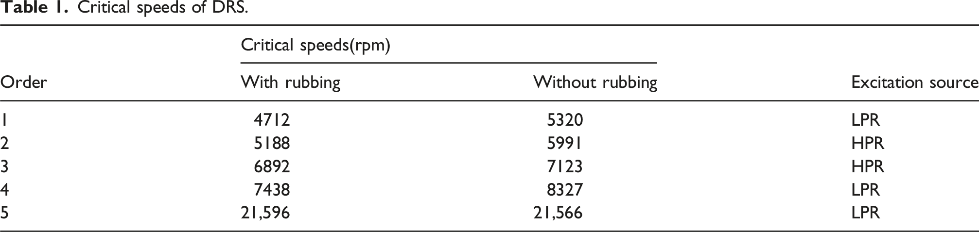
The Campbell diagram of the DRS established in this paper is shown in Figure 10. The first five orders of critical speed for DRS are shown in Table 1. Campbell diagram of DRS. (a) LPR, (b) HPR. Critical speeds of DRS.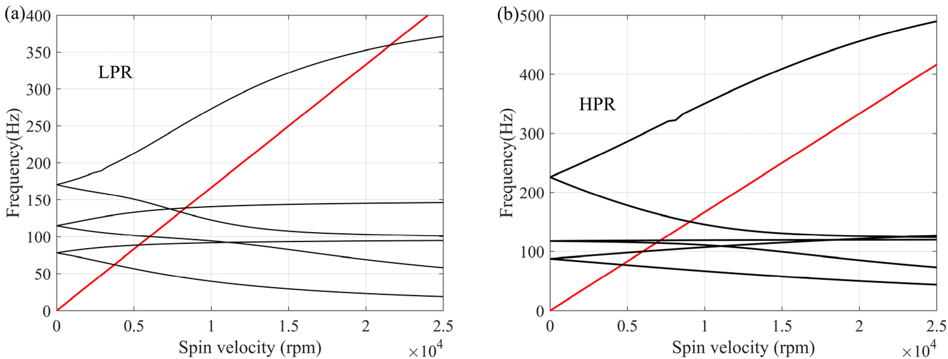
ISRI makes the HPR and LPR directly contact, which means adding a support at rubbing node. This support is simulated by linear spring. And contact stiffness kc is 5 × 10⁶ N/m. Horizontal and vertical stiffnesses of support are set to be symmetrical, k x = k y = k c . The rubbing node are the fourth node of LPR and the second node of HPR.
The Campbell diagram of DRS with ISRI is shown in Figure 11. Compared the critical speeds with and without rubbing in Table 1, it is found that the critical speeds of DRS decline due to ISRI. This result originates from the fact that gyroscopic moment reduces the stiffness of HPR and LPR when the rotation speed in counter-rotating DRS increases., which results in the decrease of critical speeds of DRS. Campbell diagram of DRS with ISRI.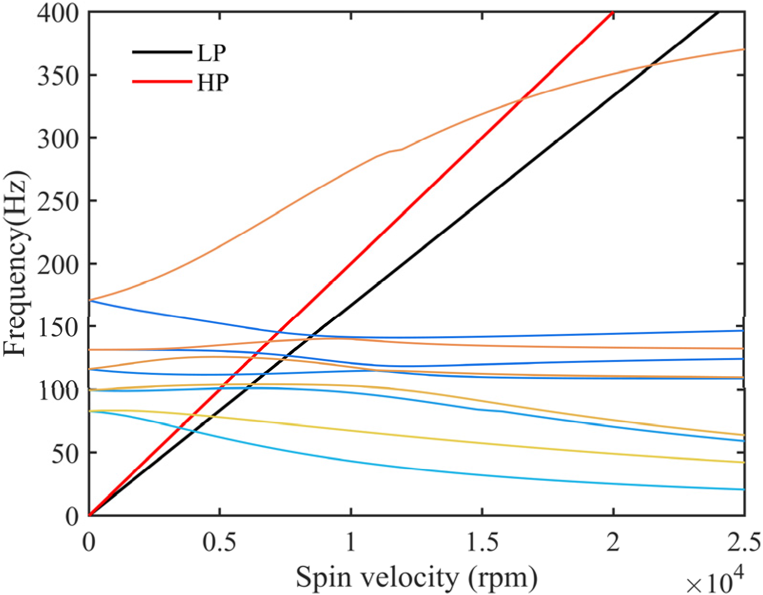
Analysis of the dynamic response of rotor system
Parameters of SDSG.
The radial displacement of HPR and LPR rubbing positions can be used as the criterion to judgment whether rubbing occurs by equation (31). δmax and δmin are the maximum and minimum values of radial displacement between HPR and LPR at rubbing position respectively. When δmax<Δ0, there is no rub-impact between HPR and LPR. When δmin<Δ0<δmax, the rubbing states are intermittent. When δmin> Δ0, continuous rub-impact occurs.
Figure 12(a) and (b) are the variation curves of the δmax and δmin in the [2000 rpm, 16,000 rpm]. In Figure 12(a), without electromagnetic excitation, the intermittent rub-impact occurs when 4081 rpm<Ω
l
<4693 rpm, 5271 rpm<Ω
l
<5402 rpm, and 6762 rpm<Ω
l
<11,198 rpm, the continuous rub-impact occurs when 4693 rpm<Ω
l
<5271 rpm and 5402 rpm<Ω
l
<6762 rpm. In Figure 12(b), with electromagnetic excitation in the DRS, intermittent rub-impact occurs when 2000 rpm<Ω
l
<5521 rpm, 6114 rpm<Ω
l
<6416 rpm, and 7901 rpm<Ω
l
<16,000 rpm, continuous rub-impact occurs when 5521 rpm<Ω
l
<6114 rpm and 6416 rpm<Ω
l
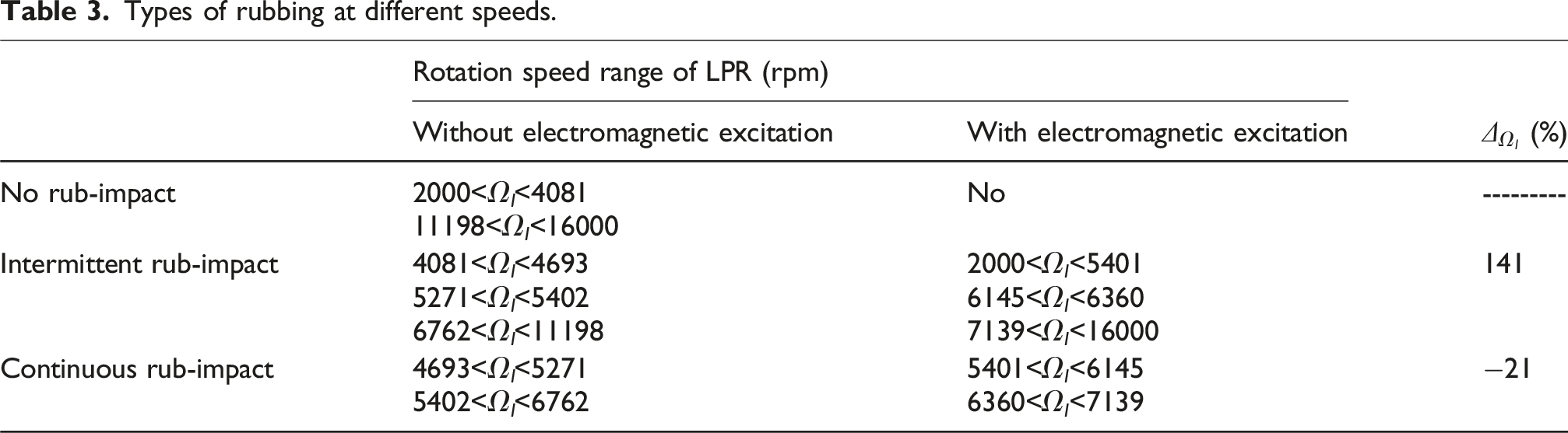
<7091 rpm. The types of rubbing are shown in Table 3. Electromagnetic excitation increases the speed range of intermittent rub-impact in the DRS by 141% and reduces the speed range of continuous rub-impact in the DRS by 21%. Without considering the electromagnetic excitation, the LPR system far away from the critical speed does not experience ISRI. The ISRI also occurs in the non-critical speed range of DRS with electromagnetic excitation. This shows the addition of electromagnetic excitation has a significant impact on the DRS dynamics, which should be fully considered in the structural design and analysis of aero-engine spindle direct-drive DRS. The radial displacement of rubbing nodes. (a) Without electromagnetic excitation, (b) With electromagnetic excitation. Types of rubbing at different speeds.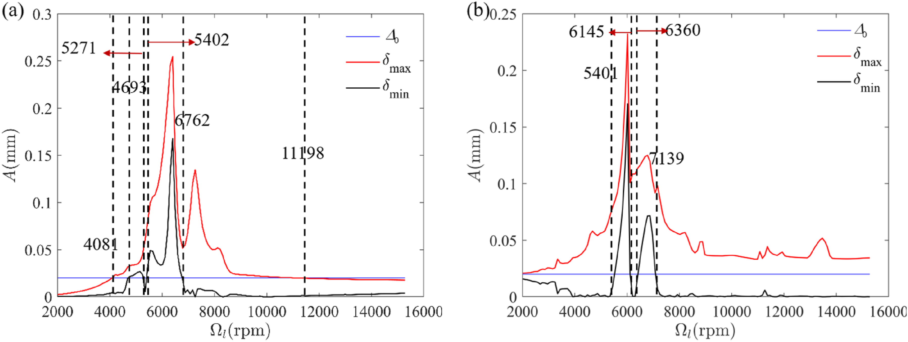
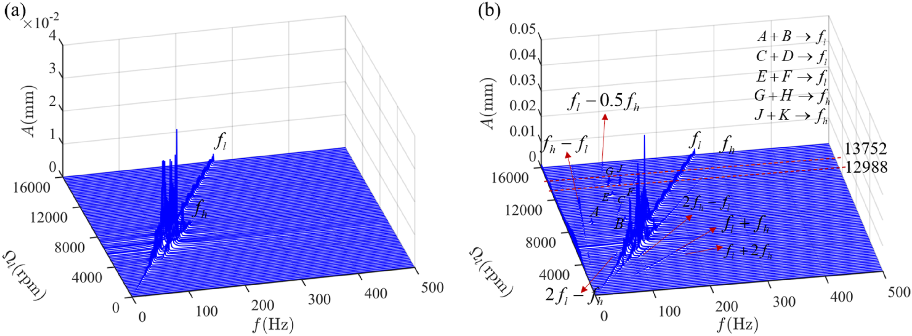
Figures 13–14 are the bifurcation diagram and displacement spectrum waterfall diagram of LPR. In Figure 13(a), without electromagnetic excitation, when Ω
l
<4081 rpm, rub-impact has not occurred, which can be verified form Figure 12(a). And LPR system stabilizes in the 1T-periodic motion. When 4081 rpm<Ω
l
<11,198 rpm, rub-impact has occurred and LPR system enters into 5T-periodic motion. When Ω
l
>11,198 rpm, LPR returns to 1T-periodic again. When the electromagnetic excitation is considered, in Figure 13(b), rub-impact has occurred in the [2000 rpm, 16,000 rpm], which can be verified form Figure 12(b). And LPR system stabilizes in the 5T-periodic motion. But around the 8404 rpm, 11,198 rpm, and 12,988 rpm to 13,752 rpm, LPR system enters into quasi-periodic. Figure 14(a) shows that waterfall diagram of LPR system without electromagnetic excitation. When the DRS approaches critical speed, the vibration amplitude increases rapidly, which leads to the occurrence of ISRI. And there are rotational frequency of HPR and LPR f
h
, f
l
in LPR system. Figure 14(b) shows that waterfall diagram of rotor system with electromagnetic excitation. Except for f
h
and f
l
, LPR occurs different combined frequencies of the HPR and LPR rotation speed frequency: f
h
+f
l
, 2f
h
+f
l
, f
h
+2f
l
, f
h
-f
l
, f
h
+0.5f
l
, 0.5f
h
. Around the 8404 rpm, 11,198 rpm, and 12,988 rpm to 13,752 rpm occur some fraction multiple frequencies, which corresponds to the cyclic change of rotor system in Figure 13(b). After calculating the frequency value, these fraction multiple frequencies have the following laws: A+B→f
l
, C+D→f
l
, E+F→f
l
, G+H→f
h
, J+K→f
h
. In addition, the rotation speed range of the fraction multiple frequencies correspond to the rotation speed of LPR system in quasi-periodic motion on the bifurcation diagram. Due to the initial static eccentricity, zero frequency appears in the LPR system. Its amplitude fluctuates with the change of rotation speed and generates peaks around 7000 rpm. Therefore, the vibration of rotor system not only causes the dynamic eccentricity at the SDSG position, but also affects its static eccentricity. This is due to the displacement of the HPR caused by the electromagnetic excitation, which affects the static eccentric part of the electromagnetic excitation model. In particularly, when the rotor system is transcritical, the rotor vibration amplitude reaches peak, the dynamic and initial static eccentricity also reaches peak. Bifurcation diagram of LPR. (a) Without electromagnetic excitation, (b) With electromagnetic excitation. Waterfall plot of x-direction displacement spectrum of LPR under different speed rotations. (a) Without electromagnetic excitation, (b) With electromagnetic excitation.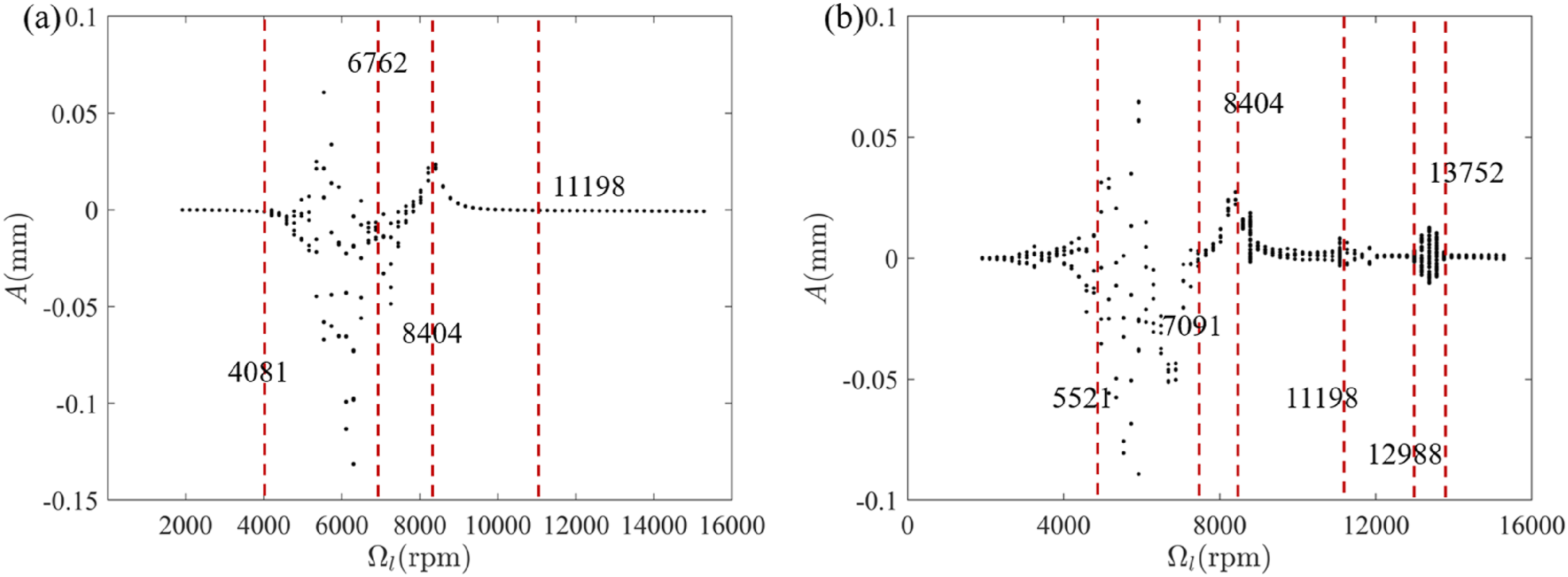
In Figure 15, the axis orbit, lateral frequency spectrum and Poincare map at several special rotation speeds are selected to further reveal the dynamic characteristics of DRS with electromagnetic excitation and IRSI. In Figure 15(a), Ω
l
= 3200 rpm, the intermittent rub-impact occurs. The axis orbit is a ring composed of some cross curves. And the rotor system occurs 5T-periodic motion, which corresponds to five separate points in the Poincare map. The f
h
is obtained from lateral frequency spectrum, which shows that rubbing has occurred at this rotation speed. In addition, there are also major frequencies such as 0 Hz, f
h
-f
l
, 2f
l
, f
h
+f
l
, 2f
h
+f
l
, f
h
+2f
l
. In Figure 15(b), the continuous rub-impact occurs. The axis orbit is a circular ring. The lateral frequency spectrum is mainly expressed as f
h
and f
l
and the amplitude of f
h
is significantly greater than that of f
l
. This is because when Ω
l
= 5896 rpm, the Ω
h
is 7076 rpm, which approaches the second order critical speed of HPR. The rotation frequency of HPR becomes main excitation source in the DRS. The LPR system occurs quasi-periodic motion. In Figure 15(c), Ω
l
= 8595 rpm, the intermittent rub-impact occurs, which can be verified form Figure 12(b), and the axis orbit of the LPR is more chaotic. Apart from the aforementioned frequency components, there are also fraction multiple frequencies A: 45 Hz and B: 98 Hz. And these frequencies are consistent with A+B→f
l
that appears in Figure 14(b). Based on the Poincare map, rotor system occurs quasi-periodic motion at this speed. In the Figure 15(d) and (e), the LPR rotation speeds are 11,078 rpm and 13,370 rpm, respectively, the intermittent rub-impact occurs at this time. And the axis orbit of the LPR is more chaotic than the previous rotation speeds. Similarly, in addition to the f
h
, f
l
and combined frequency in the lateral frequency spectrum, there are also fraction multiple frequencies C: 62 Hz, E: 86 Hz, F: 99 Hz and D: 123 Hz in the Figure 15(d), and G: 102 Hz, J: 121 Hz, K: 146 Hz and H: 166 Hz in the Figure 15(e). And these frequencies are consistent with C+D→f
l
, E+F→f
l
, G+H→f
h
, J+K→f
h
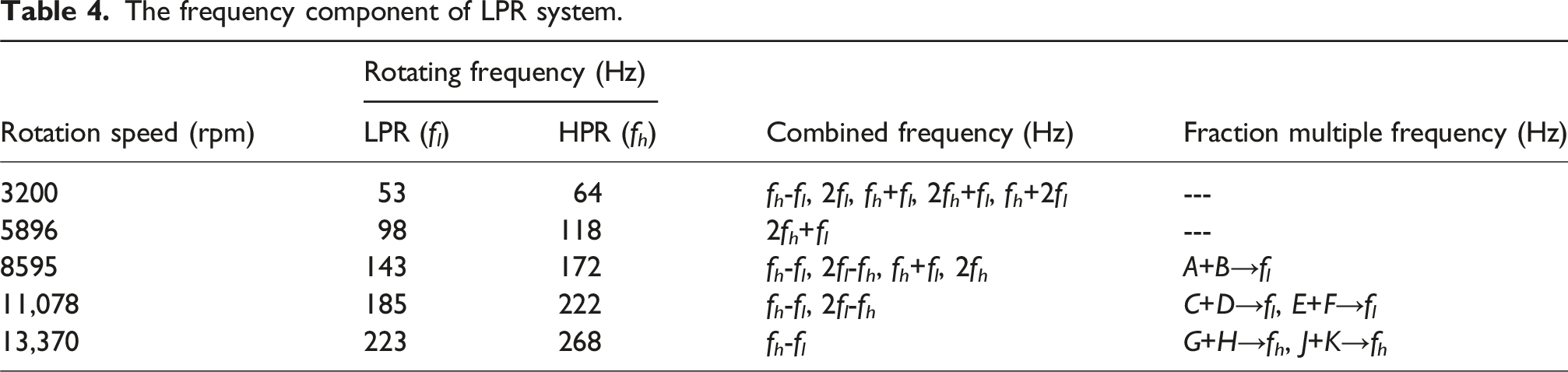
that appears in Figure 14(b). Based on the Poincare map, rotor system occurs quasi-periodic motion at 11,078 rpm and 11,370 rpm. In summary, when electromagnetic excitation is not considered, there are only f
h
and f
l
in the rotor system. When considering electromagnetic excitation, some combined frequencies and fraction multiple frequencies appear in LPR system at these speeds, which are listed in the Table 4. According to the bifurcation diagram and the variation curves of δmax and δmin, the LPR system occurs intermittent rub-impact and transfers from the 5T-periodic motion to the quasi-periodic motion when fraction multiple frequencies appear in the rotor. This indicates that the dynamic characteristics of spindle direct-drive DRS with electromagnetic excitation is more complicated under the intermittent rub-impact than the continuous rub-impact. Dynamic responses of the LPR system at different rotation speeds. (a) Ω
l
= 3200 rpm, (b) Ω
l
= 5896 rpm, (c) Ω
l
= 8595 rpm, (d) Ω
l
= 11,078 rpm, (e) Ω
l
= 13,370 rpm. The frequency component of LPR system.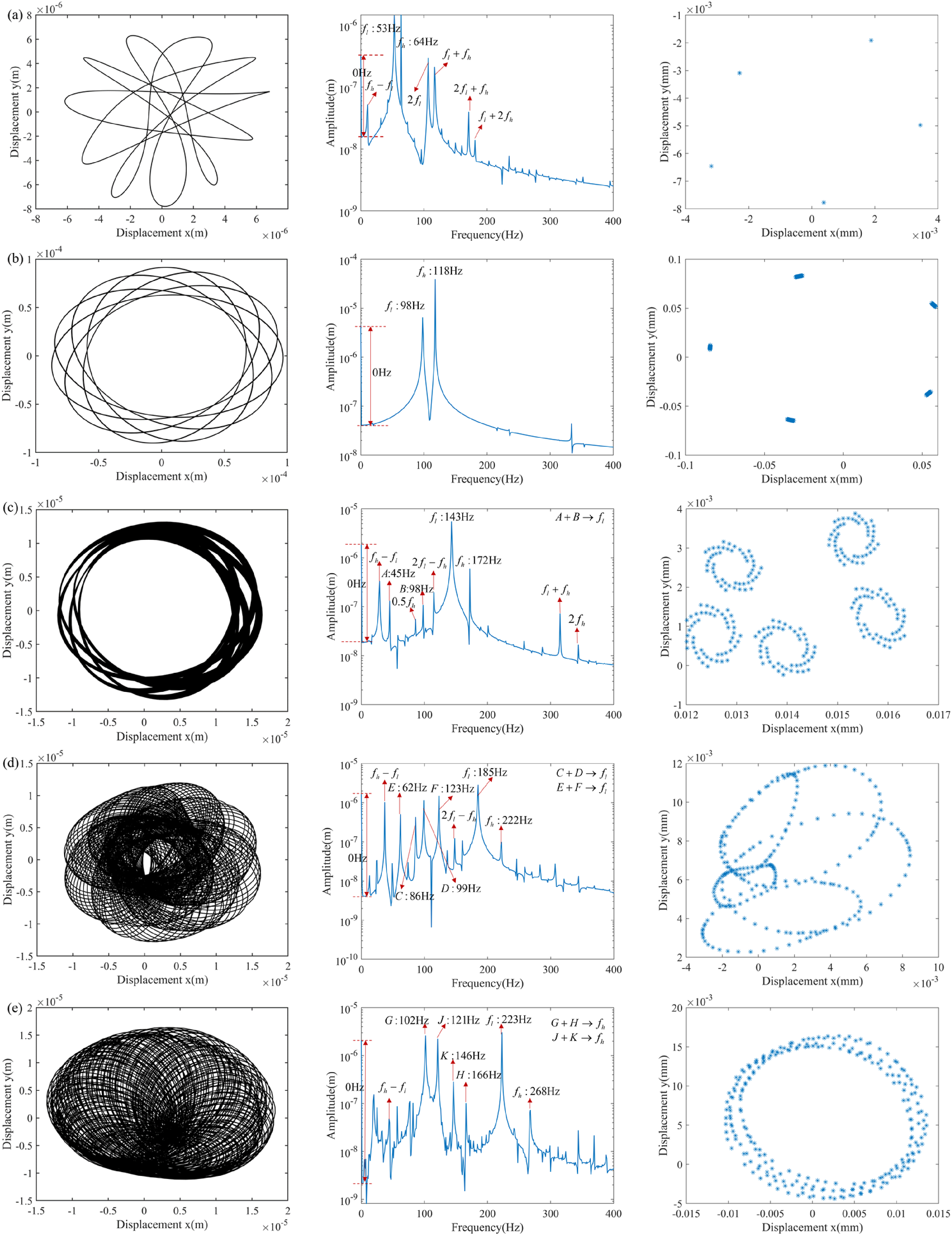
The initial static eccentricity significantly impacts both UMP and electromagnetic torque. The influence of UMP and electromagnetic torque on dynamic characteristics of ISRI DRS with different initial static eccentricities (x0) are studied. These initial static eccentricities are along the x-axis positive direction. And Ω l = 12,500 rpm, other parameters are kept constant.
Figure 16 shows the variation curves of the δmax and δmin with different x0. In Figure 12(a), when Ω
l
= 12,500 rpm, the rotor system has no rubbing without electromagnetic excitation. In Figure 16, the electromagnetic excitation is considered, when x0>3.8×10⁻⁶ m, the LPR system occurs intermittent rub-impact, and it has a peak value in the [5 × 10⁻⁶ m, 8 × 10⁻⁵ m]. When x0>1.1 × 10⁻⁴ m, the continuous rub-impact occurs. With the change of x0, the rubbing type can be summarized as follows: no rub-impact - intermittent rub-impact - continuous rub-impact. Figure 17 is bifurcation diagram of LPR system with different x0. With the increase of x0, LPR system is transformed from the 1T-periodic motion to the 5T-periodic motion. And in the range x0 = 5 × 10⁻⁵ m to x0 = 8 × 10⁻⁵ m, the points of the bifurcation diagram become disordered, which corresponds to the peak value of the δmax curve. Figure 18 is the waterfall plot of x-direction displacement spectrum of LPR with different x0. The rotor system has some combined frequencies after rubbing, such as f
h
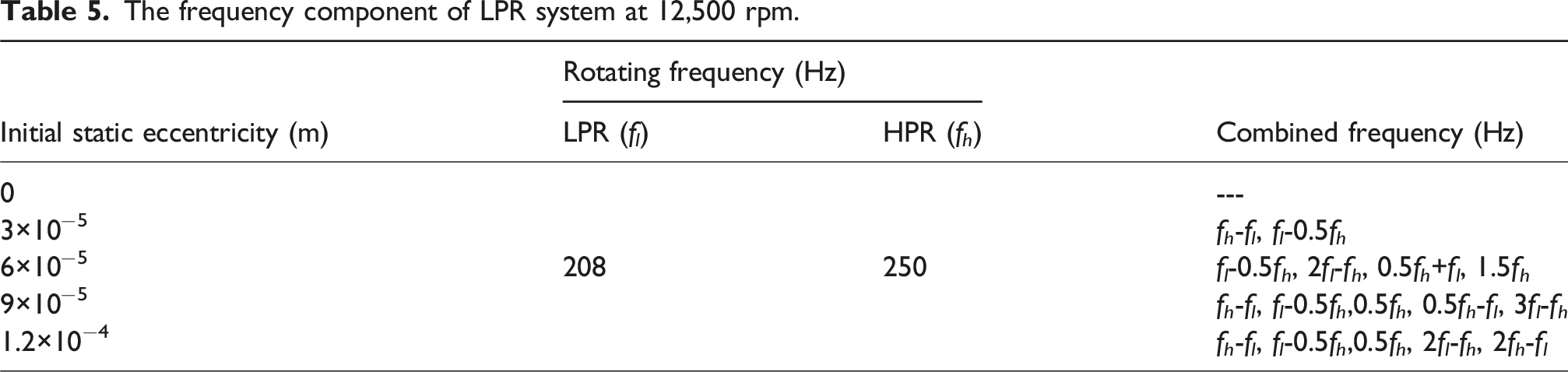
-f
l
, f
l
-0.5f
h
, 0.5f
h
, 2f
l
-f
h
, 2f
l
, 0.5f
h
+f
l
, 1.5f
h
, f
h
+f
l
. The amplitude of 0 Hz increases as the x0. This is because with the increase of x0, the electromagnetic excitation undergoes a gradual intensification. At the same time, UMP gradually plays a dominant role in external excitation. And the amplitude of zero frequency also appears a peak value in the range of x0 = 5 × 10⁻⁵ m–x0 = 8 × 10⁻⁵ m. Some combined frequencies (0.5f
h
, 0.5f
h
+f
l
) also have a peak value in this range. When Ω
l
= 12,500 rpm, 0.5f
h
is 125 Hz. In conjunction with Table 1, 0.5f
h
is the fourth-order critical speed of DRS with ISRI. When x0∈[5 × 10⁻⁵ m, 8 × 10⁻⁵ m], the amplitude of 0.5f
h
reaches a peak value, which means the occurrence of subharmonic resonance in rotor system. Therefore, the δmax curve appears peak value, the points of the bifurcation diagram become disordered, and the amplitude of 0 Hz, 0.5f
h
, 0.5f
h
+f
l
of waterfall diagram also appear peak value in this range. The critical speeds of the DRS change with the initial static eccentricity under the influence of electromagnetic excitation. When x0>8 × 10⁻⁵ m, 0.5f
h
is far away from critical speed of DRS, the δmax curve, the bifurcation diagram, and the amplitude of 0 Hz, 0.5f
h
, 0.5f
h
+f
l
of waterfall diagram exit the peak range. The radial displacement of rubbing nodes. Bifurcation diagram of LPR. Waterfall plot of x-direction displacement spectrum of LPR under different initial static eccentricities.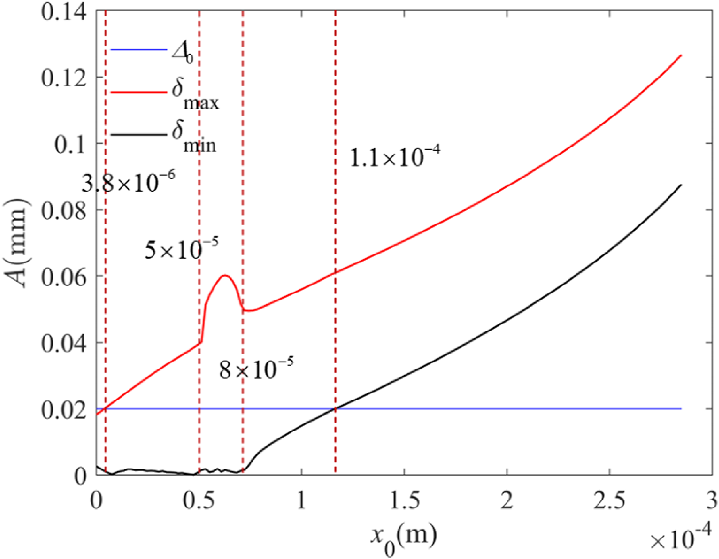
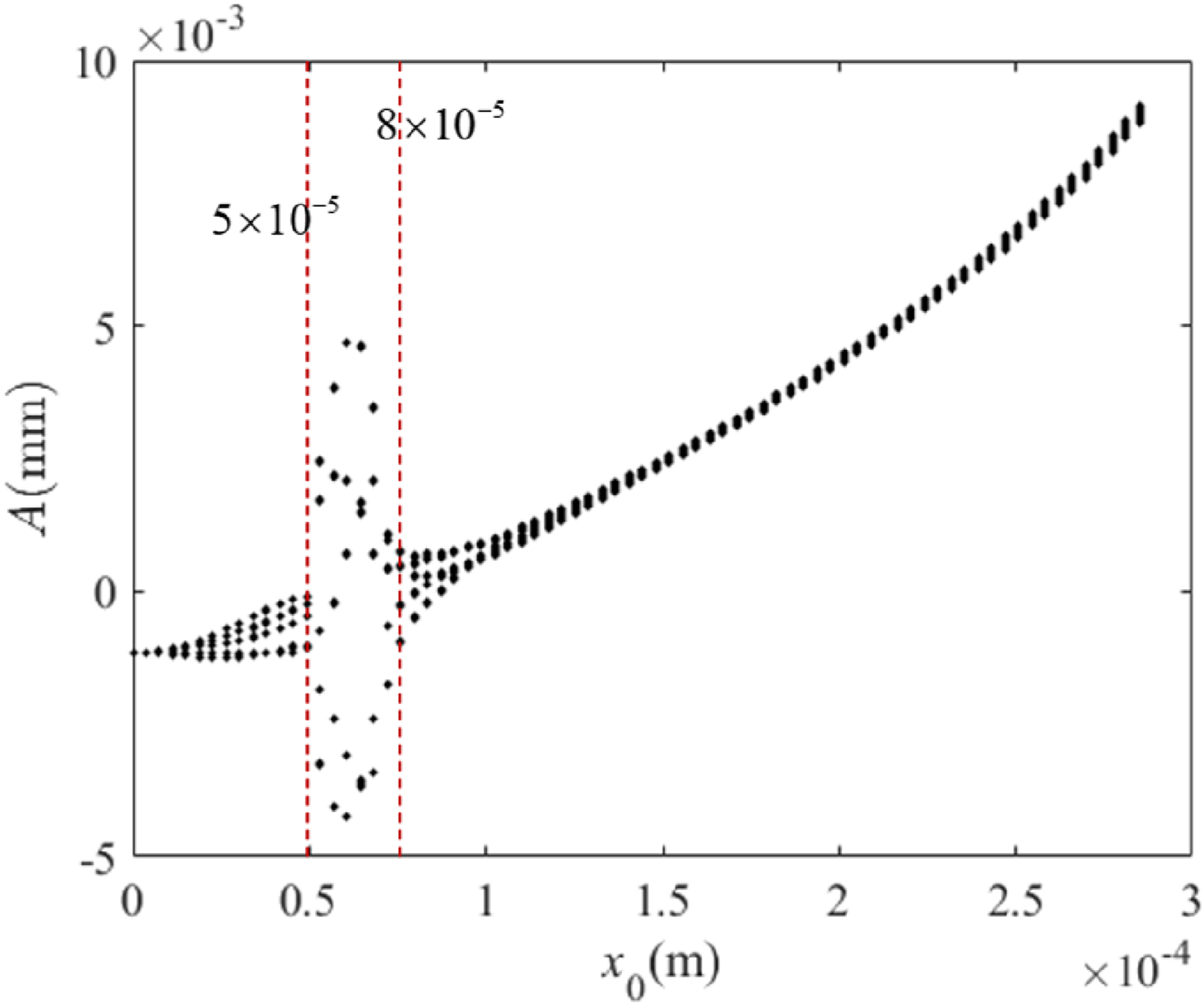
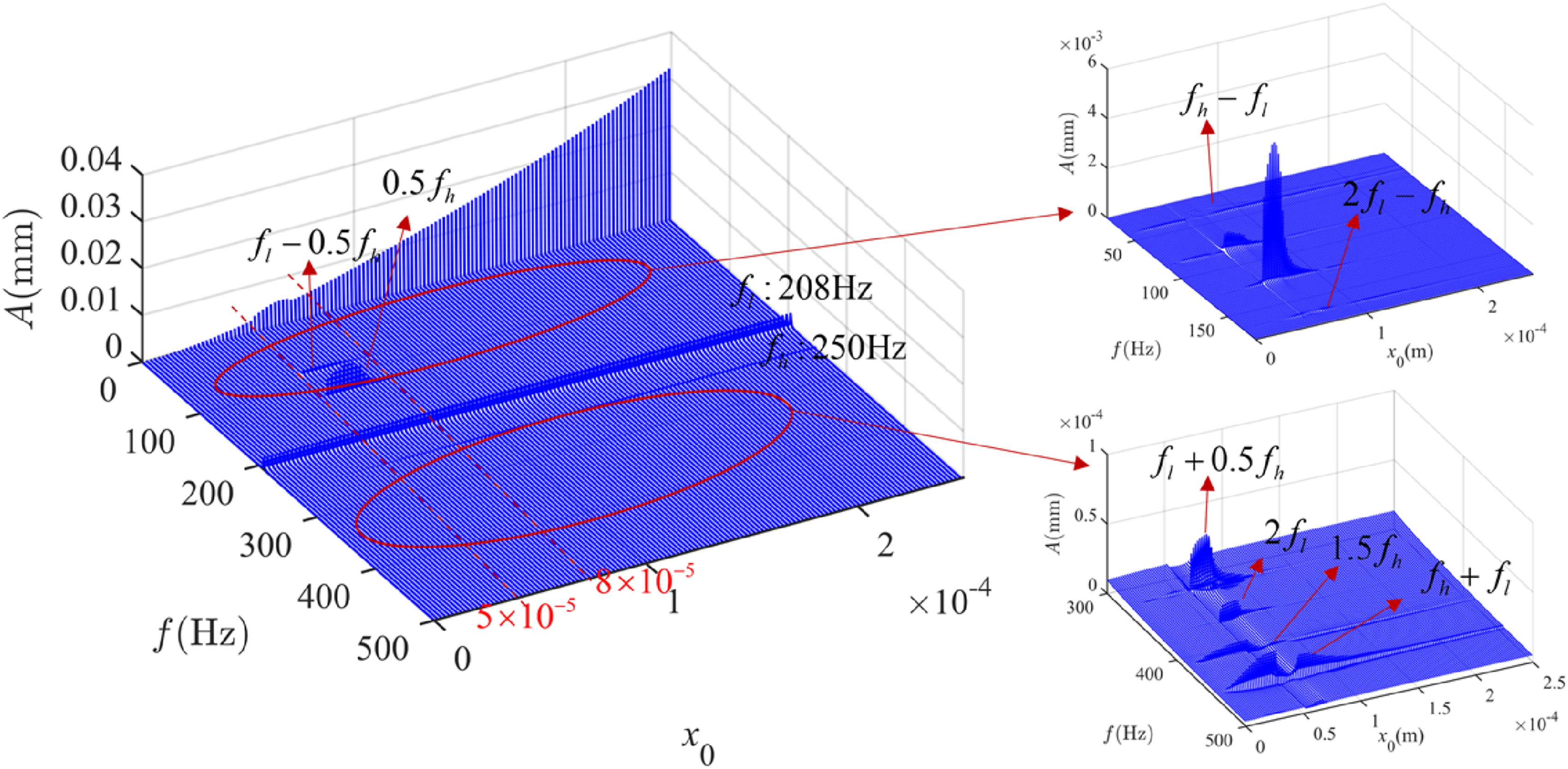
Figure 19 shows the axis orbit, lateral frequency spectrum and Poincare map of the LPR system with different initial static eccentricities. When x0 = 0 m, rotor system has no rub-impact. There is f
l
in the lateral frequency spectrum. According to Figure 16, there is no rubbing DRS under this condition and there is no energy transfer between the HPR and LPR. Therefore, there is no f
h
appearing in the LPR system. And rotor system enters into 1T-periodic, which is based on the Poincare map. In Figure 19(b), x0 = 3 × 10⁻⁵ m, the axis orbit of LPR system gradually becomes disordered. The intermittent rub-impact occurs, which can be verified from Figure 12(b). In the lateral frequency spectrum, in addition to f
l
and f
h
, rotor system also appears f
h
-f
l
, f
l
-0.5f
h
. At this time, the amplitude of f
l
is largest in frequency spectrum diagram. It shows that the unbalanced mass force occupies the dominant position in the external excitation. The presence of five distinct points on the Poincare map suggests that LPR system undergoes 5T-periodic motion. In Figure 19(c), x0 = 6×10⁻⁵ m, the rotor system occurs intermittent rub-impact. “Petals” begins to appear on the axis orbit. Compared with axis orbit with different initial static eccentricities, it is found that the number of contacts between the HPR and LPR are significantly more at this time, and the rubbing is more serious. The amplitude of 0 Hz and 0.5f
h
is significantly greater than the amplitude of f
l
. This shows that in the LPR system, 0.5f
h
and zero frequency dominate the external excitation. This is because when x0 = 6 × 10⁻⁵ m, 0.5f
h
is the fourth-order critical speed of DRS, which leads to subharmonic resonance of LPR system. And in Figure 18, when x0>5 × 10⁻⁵ m, zero frequency dominate the external excitation. When x0 = 9 × 10⁻⁵ m and x0 = 1.2 × 10⁻⁴ m, the axis orbit, lateral frequency spectrum and Poincare map of LPR are similar to Figure 19(b). The characteristic frequency components induced by the low-pressure rotor system with initial static eccentricity are summarized in Table 5. Dynamic responses of the LPR system at different x0. (a) x0 = 0 m, (b) x0 = 3 × 10⁻⁵ m, (c) x0 = 6 × 10⁻⁵ m, (d) x0 = 9 × 10⁻⁵ m, (e) x0 = 1.2 × 10⁻⁴ m. The frequency component of LPR system at 12,500 rpm.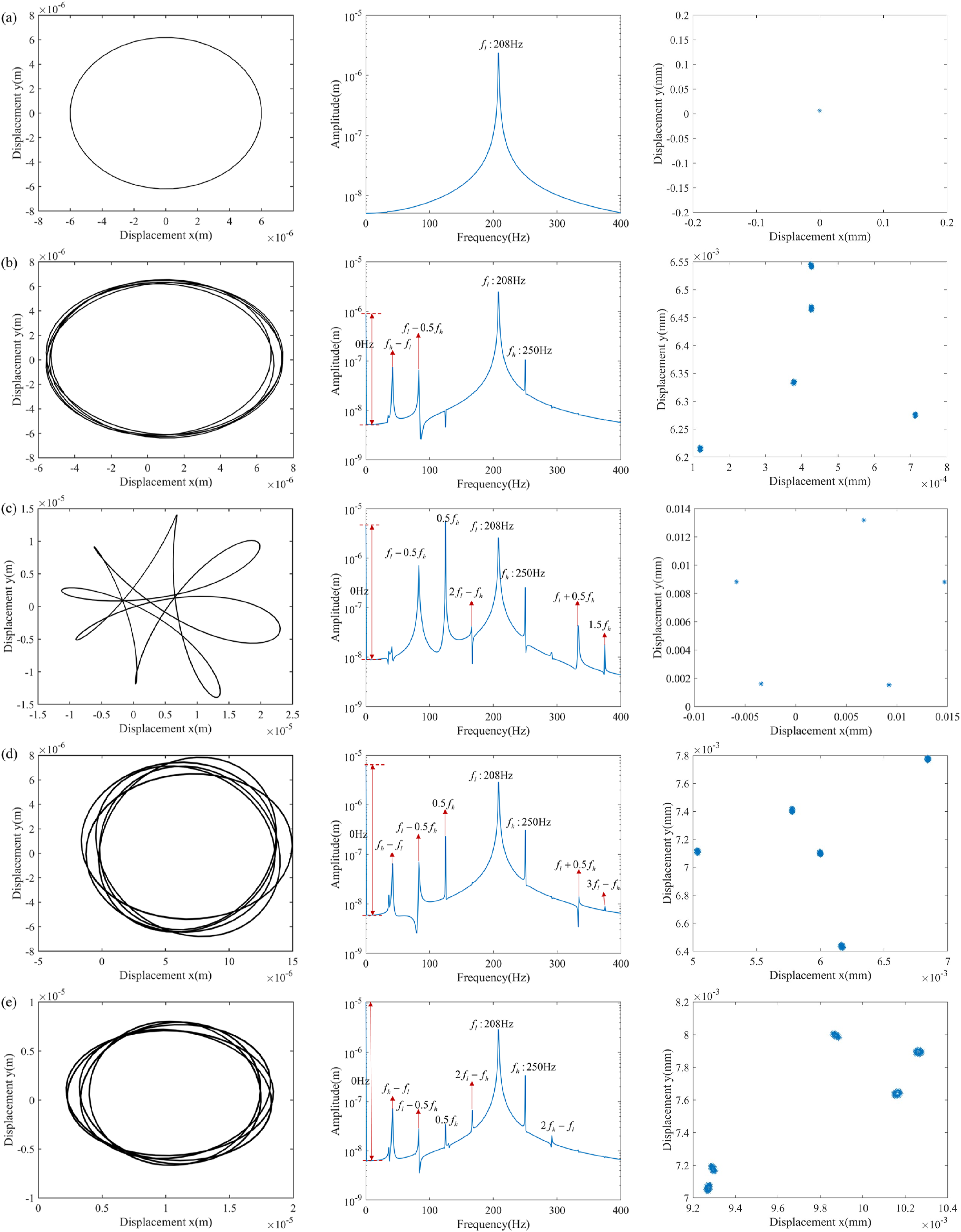
The vibration of DRS caused by unbalanced mass during aero-engine operation. This leads to the dynamic eccentricity in the SDSG. Therefore, the effect of dynamic eccentricity on the dynamic characteristics of DRS is described by taking mass eccentricity as control parameter. The x0 is zero. LPR rotation speed is Ω l = 12,500 rpm. As shown in Figure 12(a) and Figure 16, whether or not electromagnetic excitation is considered, there is no rub-impact between HPR and LPR at this case. And the mass eccentricity of Disk3 (e3) is used as a control parameter to study the influence of its variation on DRS with electromagnetic excitation and IRSI. And unbalanced mass eccentricities of other disks are 1×10⁻⁵ m.
Figures 20–22 show the variation curves of δmax and δmin, bifurcation diagram, and waterfall diagram with different e3. Comparison with Figure 12(a), Figures 20(a)–22(a) add a rigid disk (Disk3) to the DRS. In Figure 20(a), when e3 is greater than 9.57 × 10⁻⁶ m, the DRS will occur intermittent rub-impact. When e3 is greater than 1.96 × 10⁻⁴ m, the DRS occurs continuous rub-impact. In Figure 20(b), the electromagnetic excitation is considered, the DRS does not have rubbing when e3<2.38 × 10⁻⁵ m, intermittent rub-impact occurs when 2.38 × 10⁻⁵ m<e3<1.86 × 10⁻⁴ m, and continuous rub-impact occurs when e3>1.86 × 10⁻⁴ m. In conclusion, when e3 is increased, the DRS experiences no rub-impact - intermittent rub-impact - continuous rub-impact. When considering the influence of electromagnetic excitation, the minimum e3 for intermittent rub-impact to occur in DRS is increased from 9.57 × 10⁻⁶ m to 2.38 × 10⁻⁵ m. And the minimum e3 for continuous rub-impact to occur in DRS is decreased from 1.96 × 10⁻⁴ m to 1.86 × 10⁻⁴ m. It can be seen that when electromagnetic excitation is considered, the mass eccentricity of Disk3 margin for the occurrence of intermittent rub-impact in DRS increases by about 149%. The margin for the occurrence of continuous rub-impact in DRS decreases by about 5%, which can be considered to remain essentially unchanged. Therefore, electromagnetic excitation shortens the range of mass eccentricity of Disk3 for the occurrence of intermittent rub-impact, which suppresses the vibration of DRS to a certain extent. In Figure 21(a), without electromagnetic excitation, when e3<9.57 × 10⁻⁶ m, the LPR system occurs 1T-period motion and when e3>9.57 × 10⁻⁶ m, the LPR system occurs 5T-period motion. In Figure 21(b), with the electromagnetic excitation, when e3<2.38×10⁻⁵ m, the rotor system occurs 1T-period motion and when e3>2.38×10⁻⁵ m, the rotor system occurs 5T-period motion. In the waterfall diagram, whether or not the electromagnetic excitation is considered, when the rotor system is rubbing, in addition to the f
l
, there are also f
h
and combination frequencies f
h
-f
l
, f
l
-0.5f
h
, 0.5f
h
, 2f
h
-f
l
, etc. The radial displacement of rubbing nodes with different e3 at 12,500 rpm. (a) Without electromagnetic excitation, (b) With electromagnetic excitation. Bifurcation diagram of LPR. (a) Without electromagnetic excitation, (b) With electromagnetic excitation. Waterfall plot of x-direction displacement spectrum of LPR under different mass eccentricities. (a) Without electromagnetic excitation, (b) With electromagnetic excitation.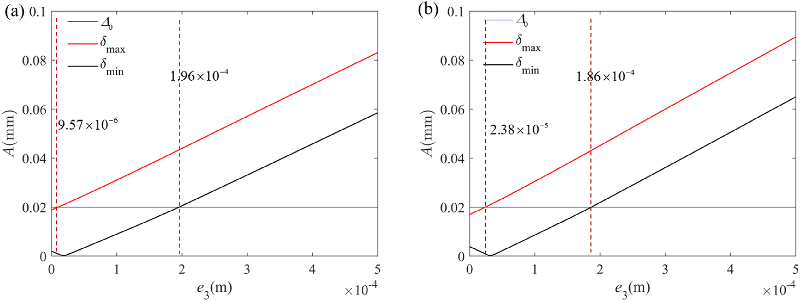
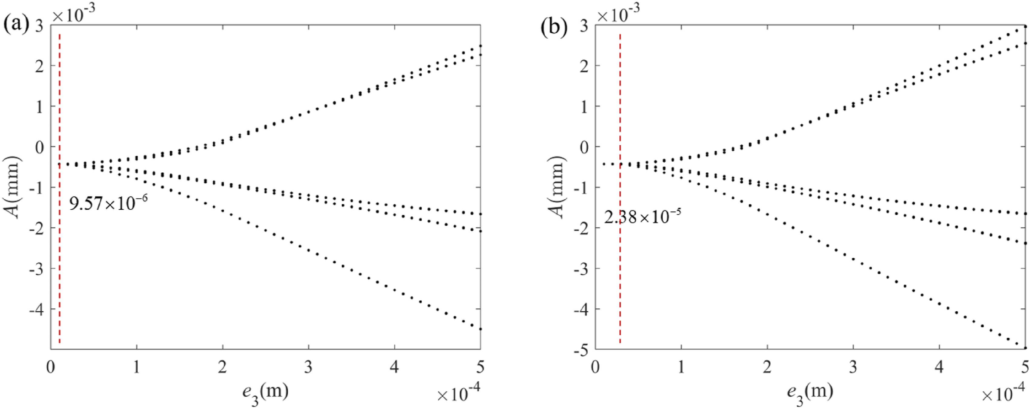
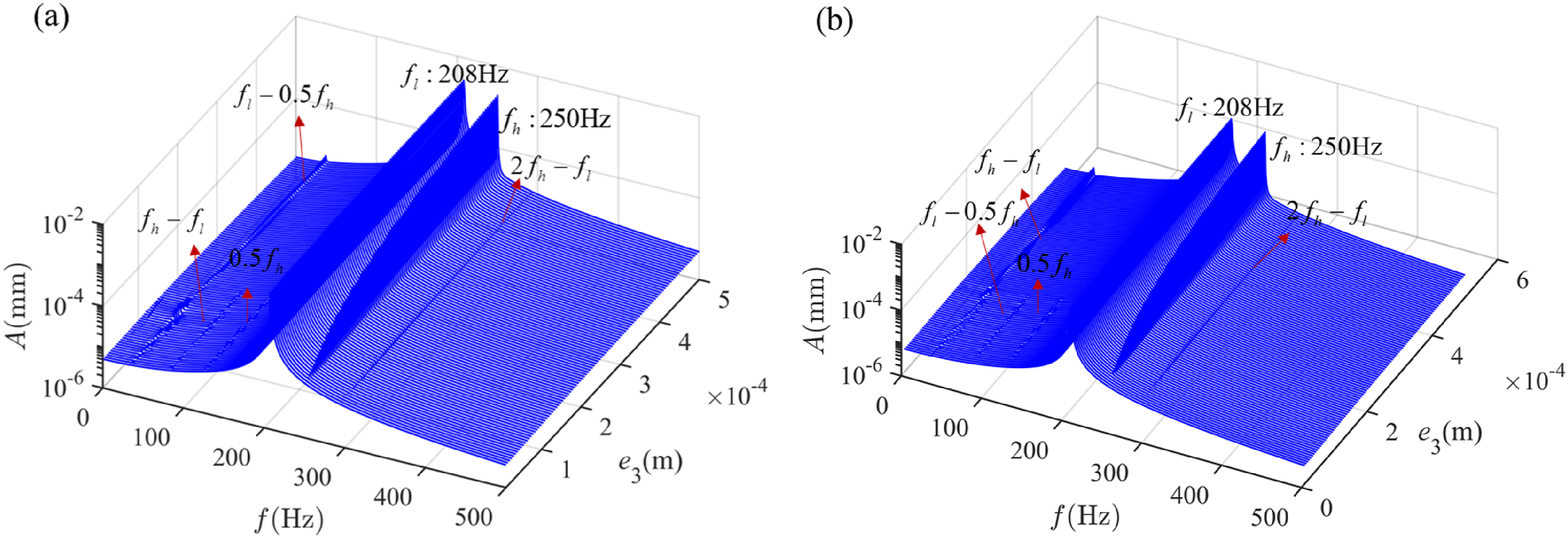
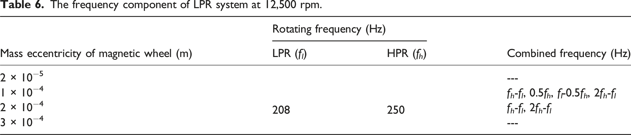
Figure 23 shows the axis orbit, lateral frequency spectrum and Poincare map of LPR system with different mass eccentricities of the Disk 3. In Figure 23(a), e3 is 2 × 10⁻⁵ m, there is only f
l
in lateral frequency spectrum. In this case, there is no rubbing of DRS under this condition and there is no energy transfer between the HPR and LPR. Therefore, there is only f
l
. And the LPR system occurs 1T-periodic. In Figure 23(b), e3 = 1 × 10⁻⁴ m, the DRS has intermittent rub-impact and the axis orbit becomes a ring. The presence of five distinct points on Poincare map suggests that LPR system occurs 5T-periodic motion. In Figure 23(c)–(d), the rotor system occurs continuous rub-impact. The axis orbit gradually changed from a ring shape to a petal shape. The combination frequency of LPR system gradually decreases. The characteristic frequency components induced by the low pressure rotor system with mass eccentricity of magnetic wheel are summarized in Table 6. Dynamic responses of the LPR system at different e3 with electromagnetic excitation. (a) e3 = 2 × 10⁻⁵m, (b) e3 = 1 × 10⁻⁴m, (c) e3 = 2 × 10⁻⁴m, (d) e3 = 3 × 10⁻⁴m. The frequency component of LPR system at 12,500 rpm.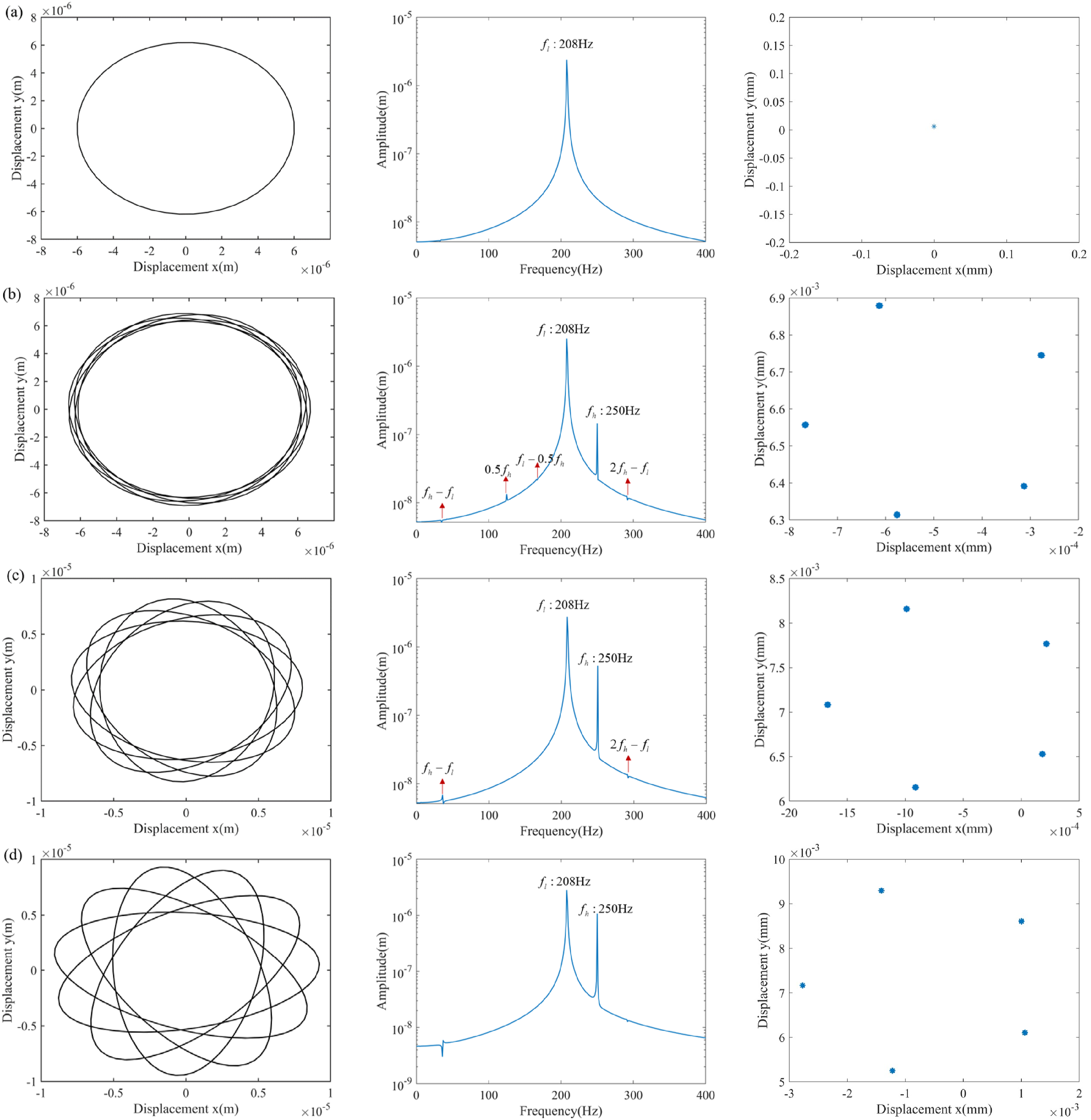
Conclusion
In this paper, the effect of electromagnetic excitation and ISRI coupling on the dynamic behavior of the DRS is studied, which provides a foundation for vibration identification and safe and stable operation of more electric aero-engine during startup. The effectiveness of the electromagnetic excitation model and the finite element modeling method is experimentally verified. Furthermore, the study examines the effects of electromagnetic excitation on the dynamic characteristics of ISRI DRS under various conditions, including different rotation speeds, initial static eccentricities, and mass eccentricities. The conclusions are as follows: (1) Considering the influence of SDSG, that is, electromagnetic excitation and the unbalanced mass of SDSG magnetic steel, the intermittent rub-impact rotation speed range of the DRS is increased by 141% and the continuous rub-impact rotation speed range is reduced by 21%. Electromagnetic excitation leads to ISRI even in the non-critical speed region of the DRS. With increasing of rotation speed, the rotor system undergoes a transformation of motion from 5T-period - quasi-period - 5T-period and intermittent rub-impact - continuous rub-impact alternation. (2) A richer combination spectrum appears in the DRS with coupling of electromagnetic excitation and ISRI, such as 2f
h
+f
l
, f
h
+2f
l
, f
h
-f
l
, f
h
+0.5f
l
. In addition, there are also some fraction multiple frequencies that follow certain rules, such as A+B→f
l
, C+D→f
l
, E+F→f
l
, G+H→f
h
, J+K→f
h
. (3) When initial static eccentricity x0∈ [5×10⁻⁵m, 8×10⁻⁵m], the amplitude of 0.5f
h
reaches a peak value. 0.5f
h
is the fourth-order critical speed of DRS, which causes the LPR system to subharmonic resonance. With the increase of the initial static eccentricity, electromagnetic excitation gradually occupies the main position and the rotor system experiences a complex state of no rub-impact - intermittent rub-impact - continuous rub-impact. (4) The DRS undergoes a transformation from no rub-impact - intermittent rub-impact - continuous rub-impact with the increase of the mass eccentricity of Disk3. When electromagnetic excitation is considered, the mass eccentricity of Disk3 margin for the occurrence of intermittent rub-impact increases by about 149%. The margin for the occurrence of continuous rub-impact decreases by about 5%. This indicates that electromagnetic excitation shortens the range of mass eccentricity of SDSG magnetic steel for the occurrence of intermittent rub-impact, which can suppress the vibration of DRS to a certain extent.
Footnotes
Funding
This work has been carried out with the supports of the National Natural Science Foundation of China Joint Fund Project (Nos. U2441278) and the Key Program of National Natural Science Foundation of China (Nos. 52236005).
Declaration of conflicting interests
The authors declared no potential conflicts of interest with respect to the research, authorship, and/or publication of this article.