
Abstract
The influence and mechanism of inter-shaft rub-impact have not been given a wide attention in exciting literature. This paper aims to insight into the coupled bending-torsional analysis of a counter-rotational dual-rotor system nonlinear vibration characteristics under inter-shaft rubbing fault. Firstly, a dual-rotor finite element model is established, which is based on Timoshenko beam element considering torsional deformations. In particular, the impact force is described by the nonlinear cylindrical collision model. Secondly, the modal characteristics are clarified in detail by the Campbell diagram and modal shapes diagram. Finally, the Newmark-β method is applied to solve the dual-rotor system governing equations with inter-shaft rub-impact numerically. Bifurcation diagram, three-dimensional spectrum, whirl orbit, spectrum plot, and Poincare map are used to preliminarily demonstrate the rotor system dynamic behaviors with inter-shaft rub-impact and the influences of friction coefficient and elastic modulus of the coating. Results reveal the vibration coupling effect and complicated vibration characteristics caused by inter-shaft rub-impact.
Introduction
As the core component of multiple advanced aeroengines, dual-rotor structure has been considered as a common configuration due to its greater advantages than single rotor in achieving better aerodynamic stability. In order to shorten the loads span, the inter-shaft bearing is used to connect the LPR (low pressure rotor) and HPR (high pressure rotor), which causes the coupling effect between rotors. 1 Another form of dual-rotor structure, that is, shared support-rotor system whose rotors are supported independently without inter-shaft bearing, is considered as one of the ways to lighten the engine. 2 The introduction of inter-shaft bearing or shared support-rotor system constitutes a more complex engine structure, which leads to an indirect mutual influence between the rotors. Under the effect combining multiple excitation sources and coupling vibrations, complicated dynamic behaviors of dual-rotor system could be observed. In addition, various faults may occur in the aeroengine, such as the blade-casing rub-impact, 3 rotor to stator rub-impact, 4 misalignment, 5 and bearing defects. 6 These faults will affect rotor dynamic properties and lead to aeroengine unstable operation. In severe cases, these faults will cause damage and failure of the equipment. Therefore, it is of practical significance for investigating the dual-rotor systems complicated vibration characteristics and reducing the vibrations amplitude of the whole aeroengine subjected to various faults.
The ever-changing analytical techniques and numerical models provide effective approaches to analyze the dual-rotor system dynamic response besides experiments. Thanks to decades efforts of many scholars, the lumped-mass method, 7 transfer matrix method, 8 and finite element method (FEM) 9 are verified fit for describing the dynamics of dual-rotor. The lumped-mass method is applicable to qualitative analysis of rotor, and the transfer matrix method is suitable for simple analysis, such as calculating the critical speed. The first two methods used to be applied; furthermore, the FEM has been widely used recently due to its better applicability and higher accuracy. Chen 10 introduced a new rotor-ball-bearing-casing coupling dynamic model by using FEM, and the modeling method was verified by experiments and fault simulations. Ma 11 proposed a FE model of a shaft–disk–blade system, and the model vibration subjected to rubbing between the blade-tip and casing was studied. Kang 12 established a finite element model of a dual-rotor system considering the intermediate bearing nonlinearity and studied the parameter influence on the back whirling stability through the experimental and simulation method. Additionally, Wang, 13 Lu, 14 and Ma 15 et al. adopted FEM to build respective dual-rotor systems and studied the dynamic properties. These studies demonstrated that the FEM can be considered as a powerful tool applied to the dual-rotor system nonlinear dynamic analysis.
Reducing rotor-stator clearance provides a common way to reduce specific fuel consumption and improve engine efficiency dramatically, resulting in probability of rubbing between rotating components and stationary parts. Over the past few decades, many researchers have focused primarily on the nonlinear dynamical phenomenon of rub-impact fault which is caused by other rotor system faults and has an important effect on the aeroengine reliability. Chu et al. 16 established the Jeffcott rub-impact model and found there were three paths leading to chaos with the increase of rotation speed. Patel et al. 17 proposed a rotor-stator rub-impact dynamic model by using beam element containing torsional degree of freedom, and the rubbing force was characterized by contact stiffness, damping, and Coulomb friction. Yang et al. 18 simulated the rotor system dynamic model with imbalance-fixed point rubbing coupling faults, and the influence of the material of the casing convex point on rub-impact was studied. Herisanu, N et al. 19 explored the nonlinear vibration of Jeffcott rotor with rub-impact by deriving the governing equations of the rotor and establishing an approximate analytical solution. Zhang et al. 20 developed a novel indicator for rotor system with rub-impact based on the vibration power flow theory, and the accuracy of the theoretical was validated by a corresponding test. In addition, some key phenomena and conclusions were summarized by Muszynska, 21 Jacquet-Richardet, 22 Jiang, 23 and Ma. 24
The researches mentioned above are related to the single rotor system rub-impact. Due to more complicated components, when rubbing is aroused in the dual-rotor system, it will lead to various nonlinear characteristics. In recent years, the dual-rotor rub-impact faults were revealed by many scholars through various means including theoretical analysis, numerical simulation, and experiment. Considering the nonlinear hysteretic force model, Yang et al..25,26 developed the fixed point rubbing motion equations of the dual-rotor system, and several combination frequencies were found as the particular fault frequencies in the case of fix point rubbing. Zhang et al. 27 studied the dual-rotor system dynamic vibrations with rub-impact considering bending-torsion coupling by using the Lagrange equation, the simulation results showed that the torsional vibration exhibits richer characteristic frequency. Jin et al.28,29 established a dual-rotor model considering misalignment and blade-casing rubbing, the nonlinear vibration characteristics verified by numerical simulation and experiment were revealed, and a strong self-excited vibration occurred for a small blade-tip clearance. Liu et al. 30 established an engine dual-rotor nonlinear support structure model, in which the inter-shaft bearing, squeeze film damper, casing, and nonlinear Hertz contact force from rolling bearing were considered, and nonlinear characteristics of the rubbing fault were analyzed in detail. Ma et al. 31 established a typical aeroengine dual-rotor system analytical model, and the influence of various factors, including the unbalanced position, the rotor speed, rubbing stiffness, clearance, and friction coefficient on the dual-rotor vibration response was studied. Prabith et al. 32 proposed a dual-rotor aeroengine numerical procedure for capturing the nonlinear dynamical responses and obtained substantial progress on the dual-rotor system response characteristics undergoing multi-disk rub-impact. The simulation results showed that the multi-disk rub-impact nonlinear behaviors were more complicated, and a very large amplitude was caused by the dry friction backward whirl.
Sealing structure is used in dual-rotor engines to prevent the fluid flow in adjacent paces, which may lead to interaction of rotors at the sealing installation position. 33 As a new vibration transmission way between rotors, the inter-shaft rub-impact will result in new rotors coupling modes and produce complex nonlinear characteristics. In the previous researches, a few scholars paid attention to the rubbing fault vibration characteristics. The research of Chen 34 on inter-shaft rub-impact indicated that periodic, quasi-periodic, and multi-periodic appeared in the dual-rotor system with increase of rotating speed. Based on the dual-rotor FE model considering inter-shaft rub-impact, Yu et al.35,36 compared the differences of modal characteristics and vibration when the rotor system rotated in the same and opposite directions and studied the effects of rotational speed, contact stiffness, and friction coefficient on dynamic characteristics. Generally speaking, the actual rotor–rotor contact is cylindrical contact. However, in the previous researches on inter-shaft rub-impact, impact force was all expressed by the point contact model, such as the piecewise linear model, which is difficult to describe the inter-shaft rub-impact force. Moreover, the inter-shaft rub-impact will produce friction torque on both shafts, which will affect the rotor system vibration response. Therefore, it is informative to carry out this kind of dynamical analysis of dual-rotor system for rotor system fault diagnoses and aeroengine running stability.
In this paper, a counter-rotation aeroengine dual-rotor system simulation model is established for studying nonlinear vibration with inter-shaft rub-impact. The paper structure is organized as follows. In section 2, the finite element model of a simplified dual-rotor system is proposed and the nonlinear impact force is considered. In section 3, the modal shapes, bifurcation phenomenon, and vibration responses under inter-shaft rub-impact are investigated, and the effects of different friction coefficients and elastic modulus are studied. Some conclusions are offered in section 4.
Dynamic model with inter-shaft rub-impact
Dual-rotor system finite element model
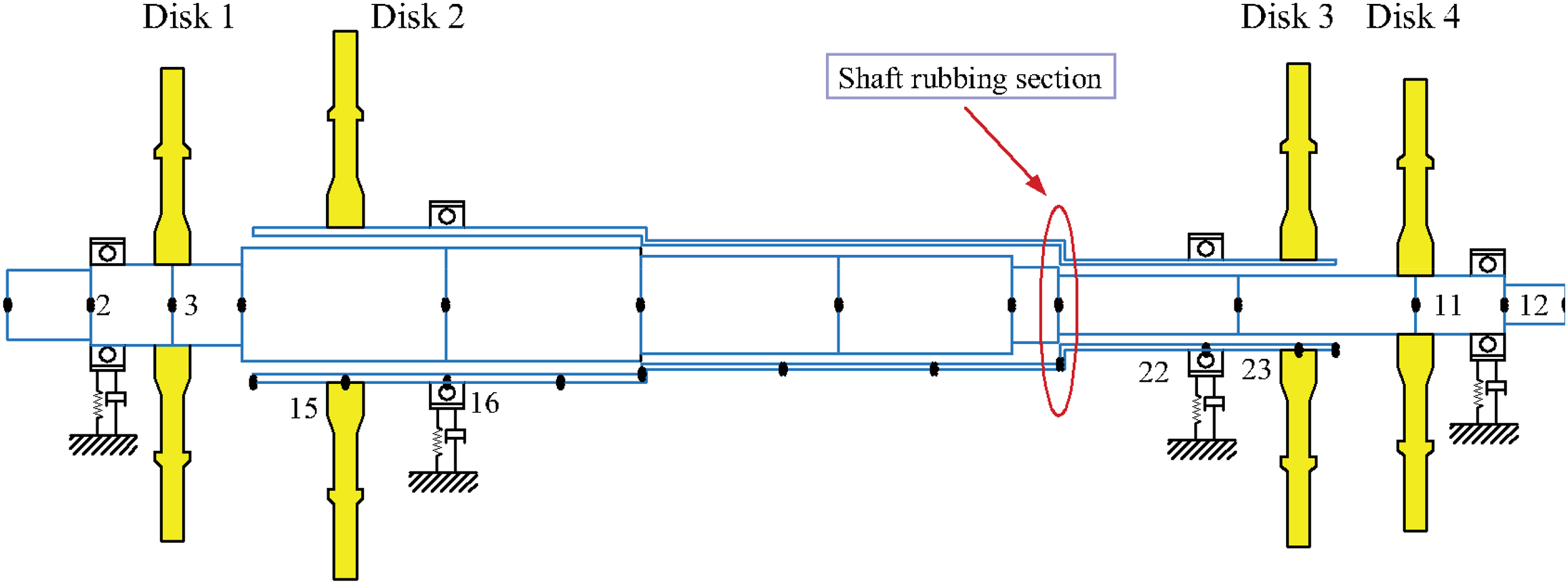
An ordinary aeroengine dual-rotor system composition is shown in Figure 1, which includes a LPR supported by bearings No. 1 and 4 in 1-0-1 manner, and a HPR supported by bearings No. 2 and 3 in 0-2-0 manner. Since the inter-shaft bearing is not adopted, so the coupling between rotors will not occur under the ideal working condition of the engine. The finite element model which can reflect the dual-rotor system nonlinear dynamic response is established. Meanwhile, the following simplification are made (1) The Timoshenko beam element model considering gyroscopic moments, rotary inertias, bending, torsional, and shear deformations is applied to simulate rotors. (2) The lumped-mass model is used to represent blades and disks, and the linear spring and elastic damping are adopted to simulate supports. (3) The LPR and HPR consist of two rigid turntables and two supports, respectively. The relative position of the rotor and the disk is shown in Figure 1. (4) The seal is fixed on the LPR, where the inter-shaft rub-impact occurs and the rubbing nodes are marked in Figure 1. (5) An abrasion-resistant coating is painted on the rubbing node surface of HPR, and the thermal effect in rub-impact is not considered. The dual-rotor system finite element model.
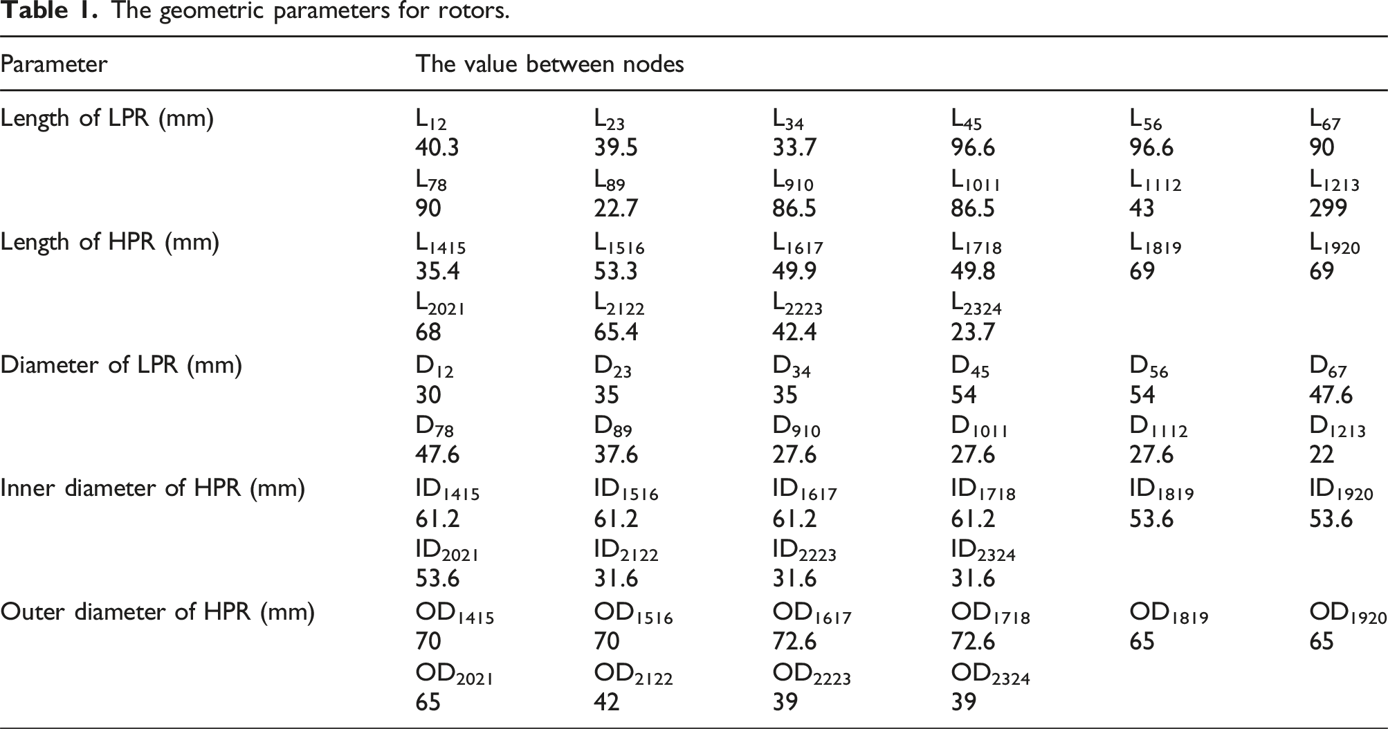
The geometric parameters for rotors.
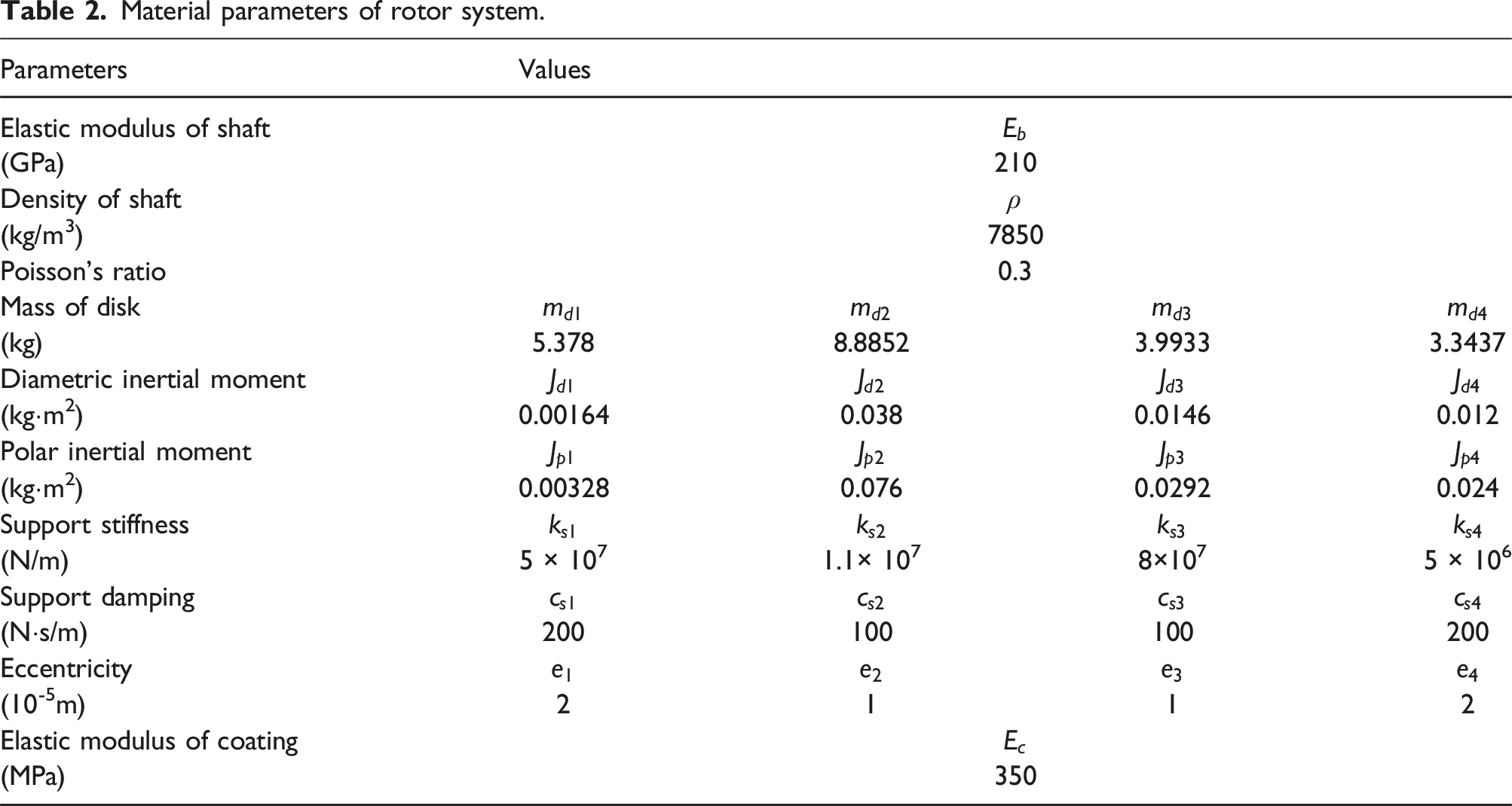
Material parameters of rotor system.
Beam element matrix
Generally, the homogeneous assumptions are made for the materials used in the rotors. As can be seen in Figure 2, the Timoshenko beam element adopted in this paper includes 2 nodes, each node contains 5-DOFs including lateral vibration and rotation in z direction. The generalized displacement vector of shaft element is defined as Discrete elements of the finite element model: (a) Timoshenko beam element and (b) disc element.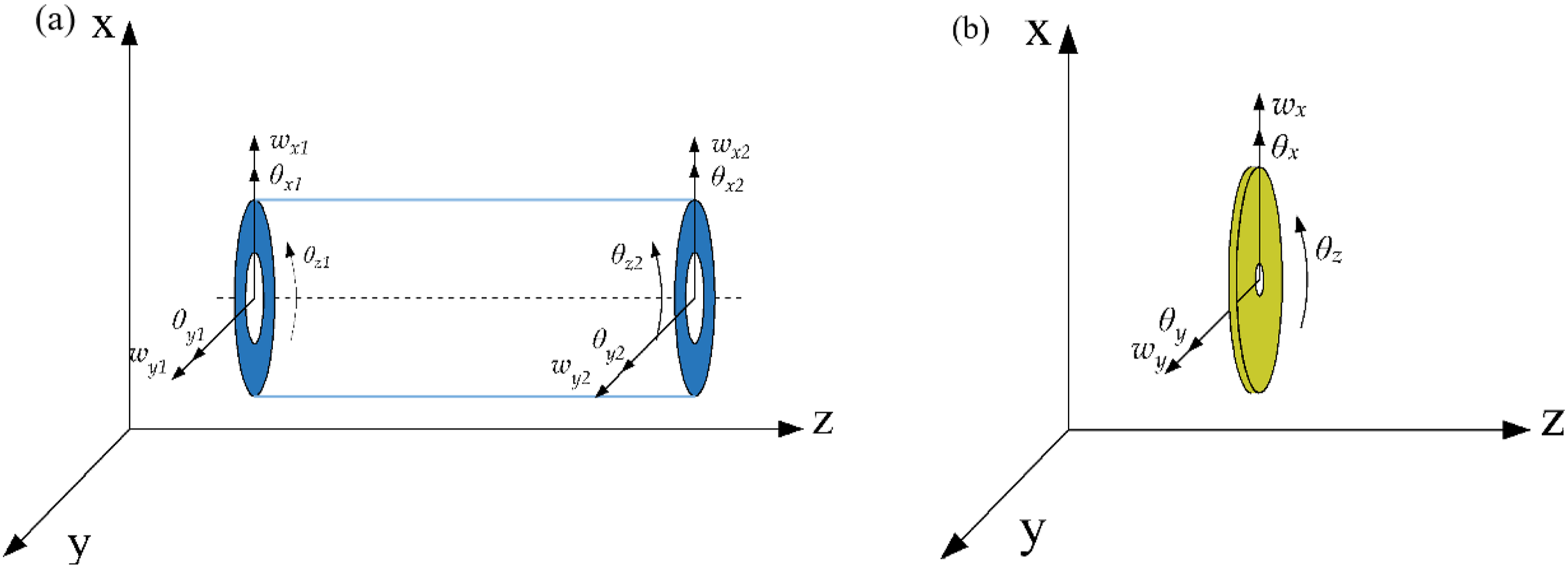
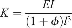
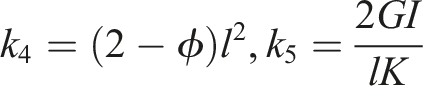
Several physical parameters of beam, including second moment of area 


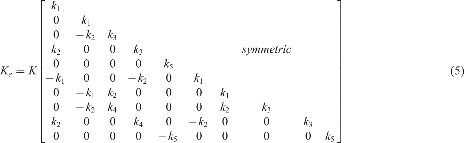
The stiffness matrix is obtained as
37

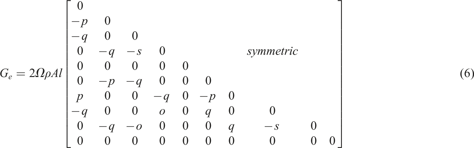
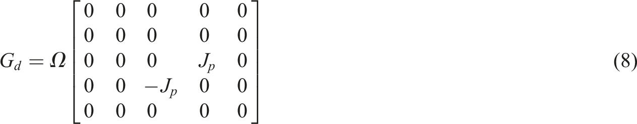
The gyroscopic matrix is obtained as
37
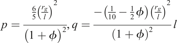
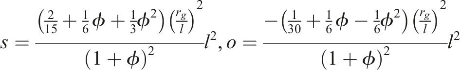
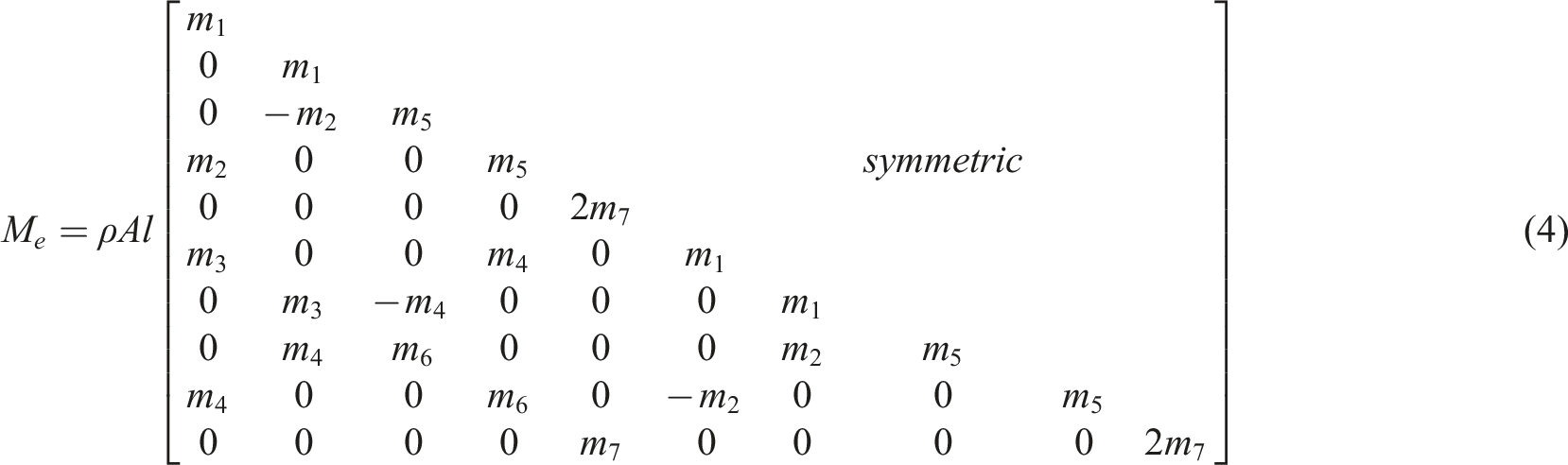
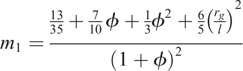
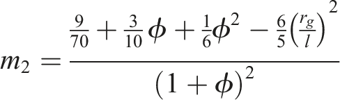
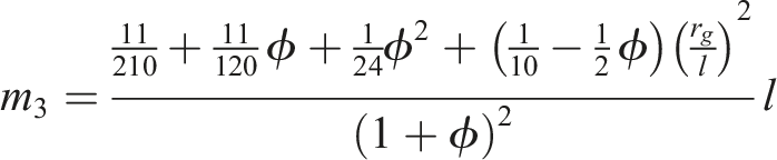
The specific expressions of mass matrix 
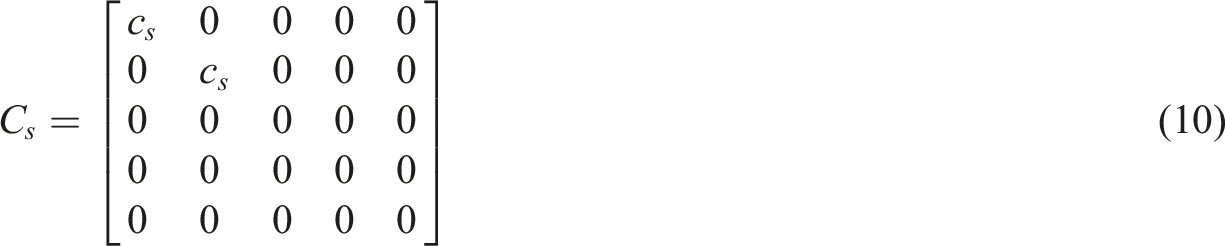
Assuming that the support is symmetrical in the x and y directions, the bearing is simulated with the linear spring-damping model to obtain satisfactory results and simplify the calculation. The element stiffness matrix and damping matrix are given by
The element matrices of disk and rotating shaft are assembled according to the corresponding node numbers to form the overall mass matrix 

Rubbing model
The accuracy of the contact force model is a crucial factor affecting the analysis results in the simulation of dynamical systems.
38
Obviously, unlike blade-casing rub-impact in the point contact framework, inter-shaft rub-impact is mechanically closer to the cylindrical contact. Meanwhile, the contact model that has been proved to be effective and widely used in point contact, such as the Lankarani-Nikravesh model, is simply a coarse approximation to estimate the contact forces between two cylindrical bodies.
39
Based on the shortcomings of point contact model and existing cylindrical contact model, a simple cylindrical contact force model is summarized by Liu et al.,
40
where contact force can be directly calculated by given penetration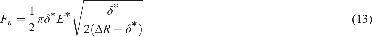
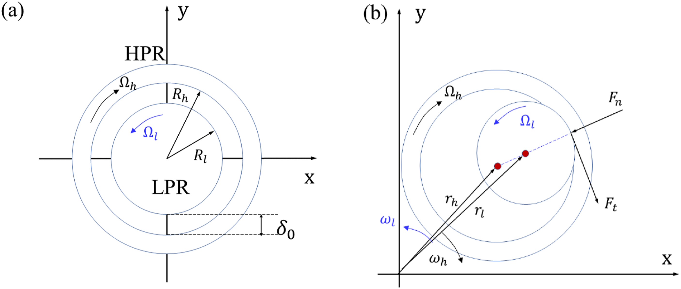
For revealing the inter-shaft rub-impact dynamic characteristic, the rubbing model between shafts is established as shown in Figure 3. The rubbing between LPR and HPR is simplified as the contact between two circles. Inter-shaft rub-impact force model: (a) Undeflected rotors and (b) rotors with inter-shaft rub-impact.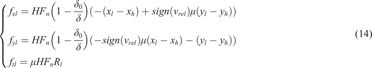


Global equation of motion
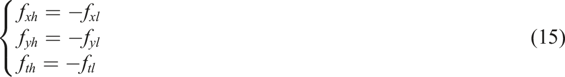
The external forces on the rotor are mainly composed of rub-impact forces and unbalance forces of the disk. The general dual-rotor system motion equation can be given by

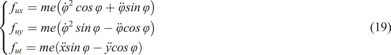

In this article, the bending-torsional coupling is reflected in two aspects: firstly, the torsion angle coordinate and the lateral displacement coordinate are coupled in the unbalanced force according to equation (19); secondly, the friction torque is a function of the lateral displacement and torsion angle according to equation (13) and equation (14).
Numerical results and discussions
Influence on inherent characteristics
In this subsection, the dual-rotor system modes and critical speeds without or with inter-shaft rub-impact are compared to further study the modal changes caused by rub-impact. The speed ratio is defined as 
By introducing column vectors, the order of equation (21) is reduced, and the second-order linear differential equation is expressed as the first-order linear differential equation:


The eigenvalues of matrix
When HPR and LPR move independently without inter-shaft rub-impact, the Campbell diagram and the first few mode shapes for each shaft are calculated separately at Campbell diagram without inter-shaft rub-impact of different shafts: (a) LPR and (b) HPR. Modal shapes for 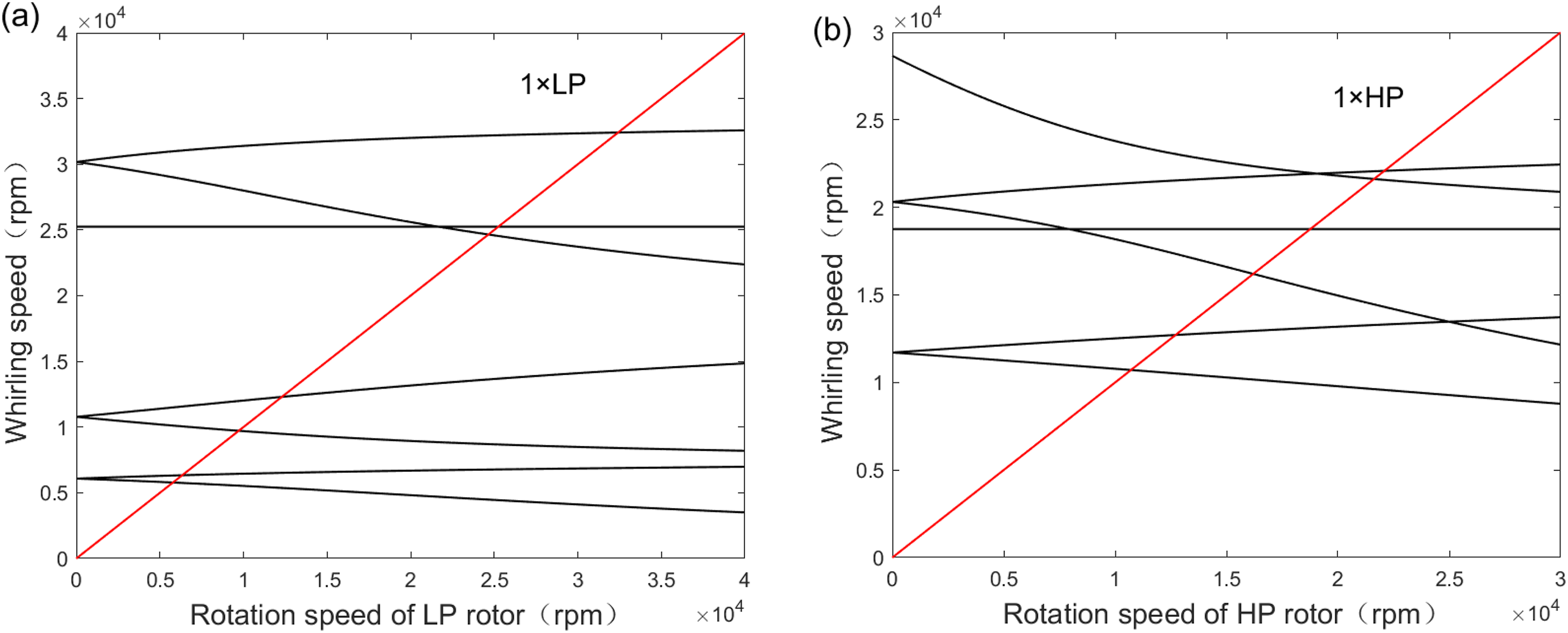
The dynamic stiffness of rotors is changed by the introduction of rubbing force, which means adding a support at the rub-impact node. In general, the support stiffness 
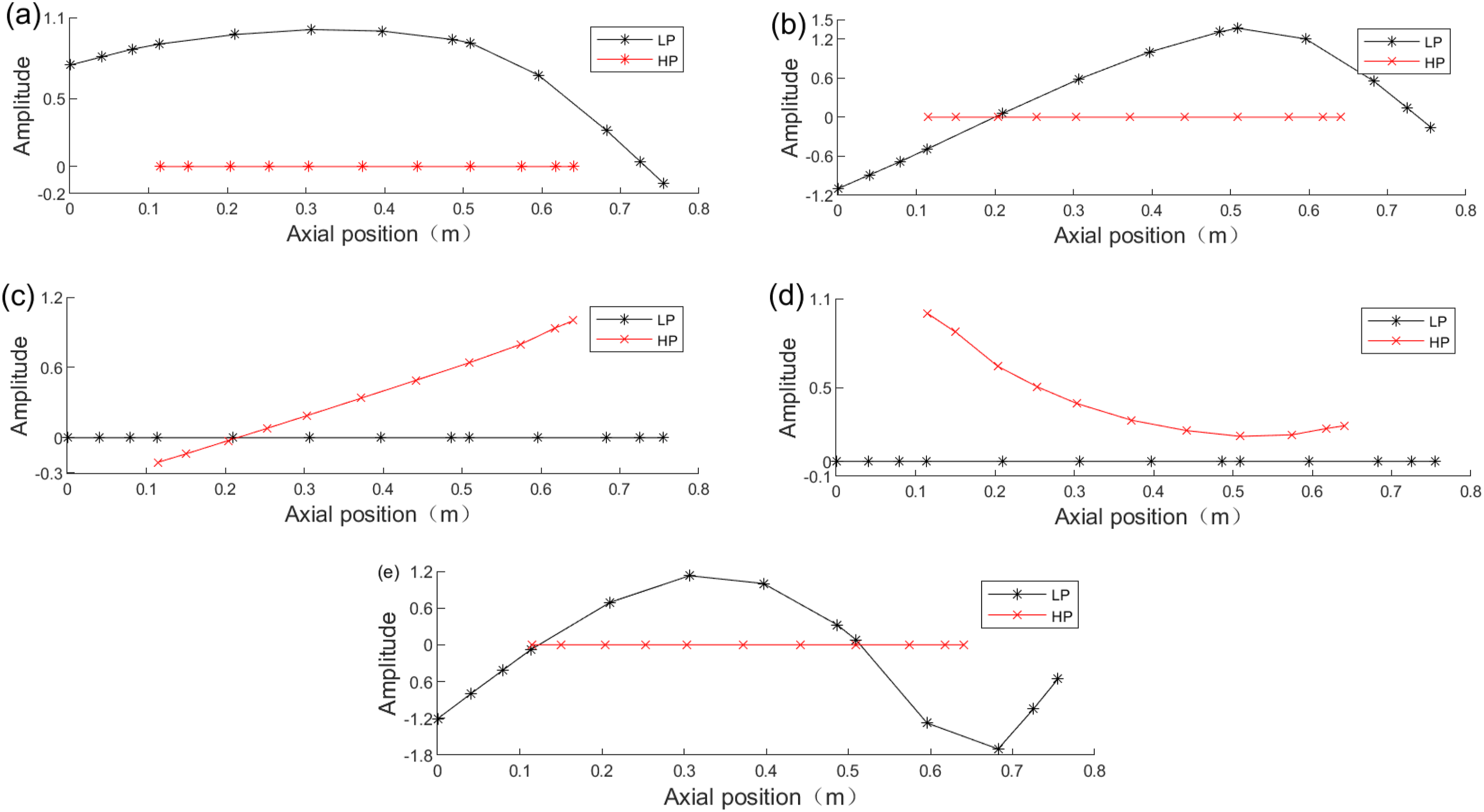
The Campbell diagrams and vibration modes corresponding to the first five modal characteristics at Campbell diagram considering rubbing as elastic spring, Modal shapes considering rubbing as elastic spring (a) n = 1+, (b) n = 2+, (c) n = 3+, (d) n = 4+, and (e) n = 5+ for Table of critical speeds with rubbing and without rubbing.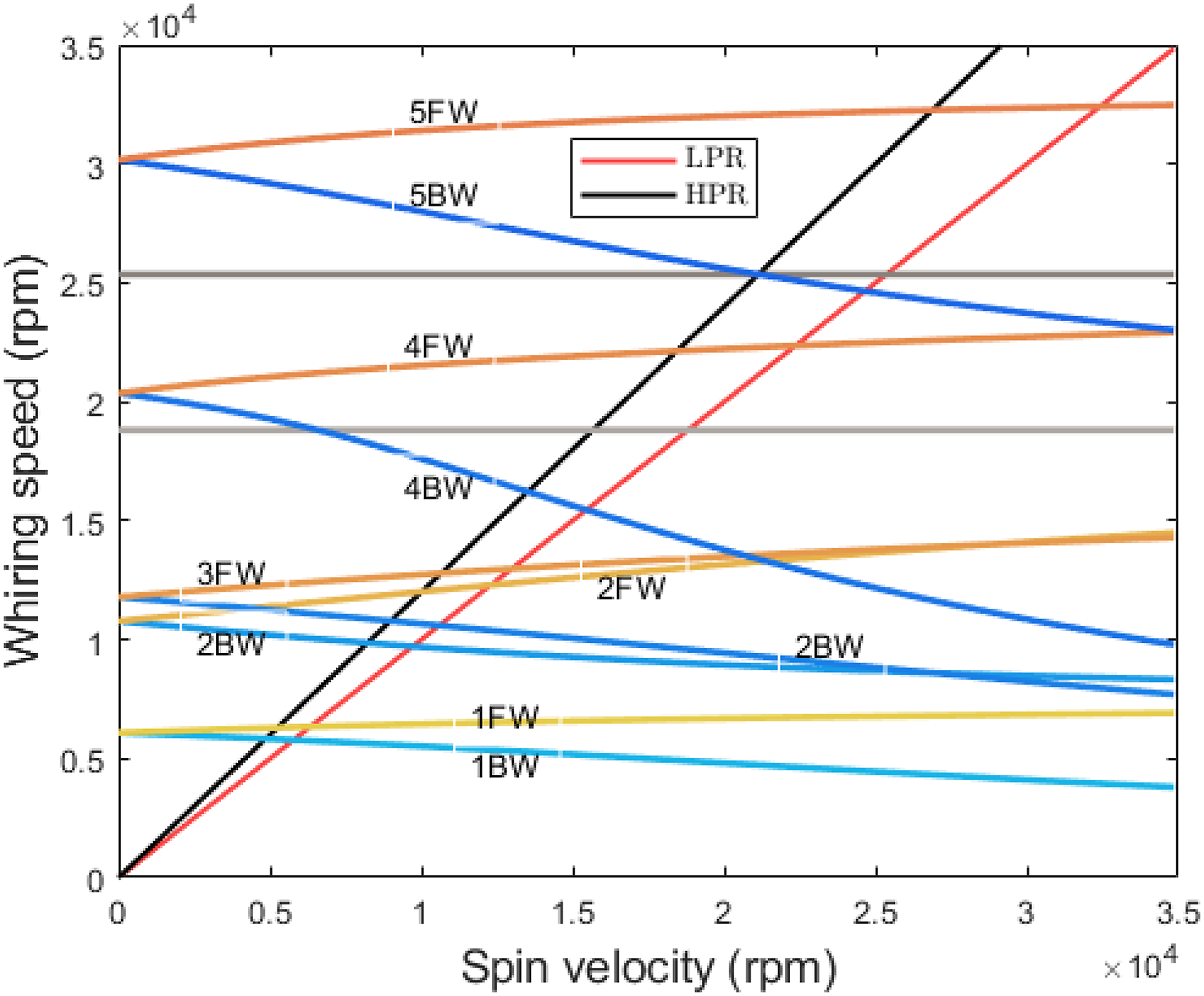
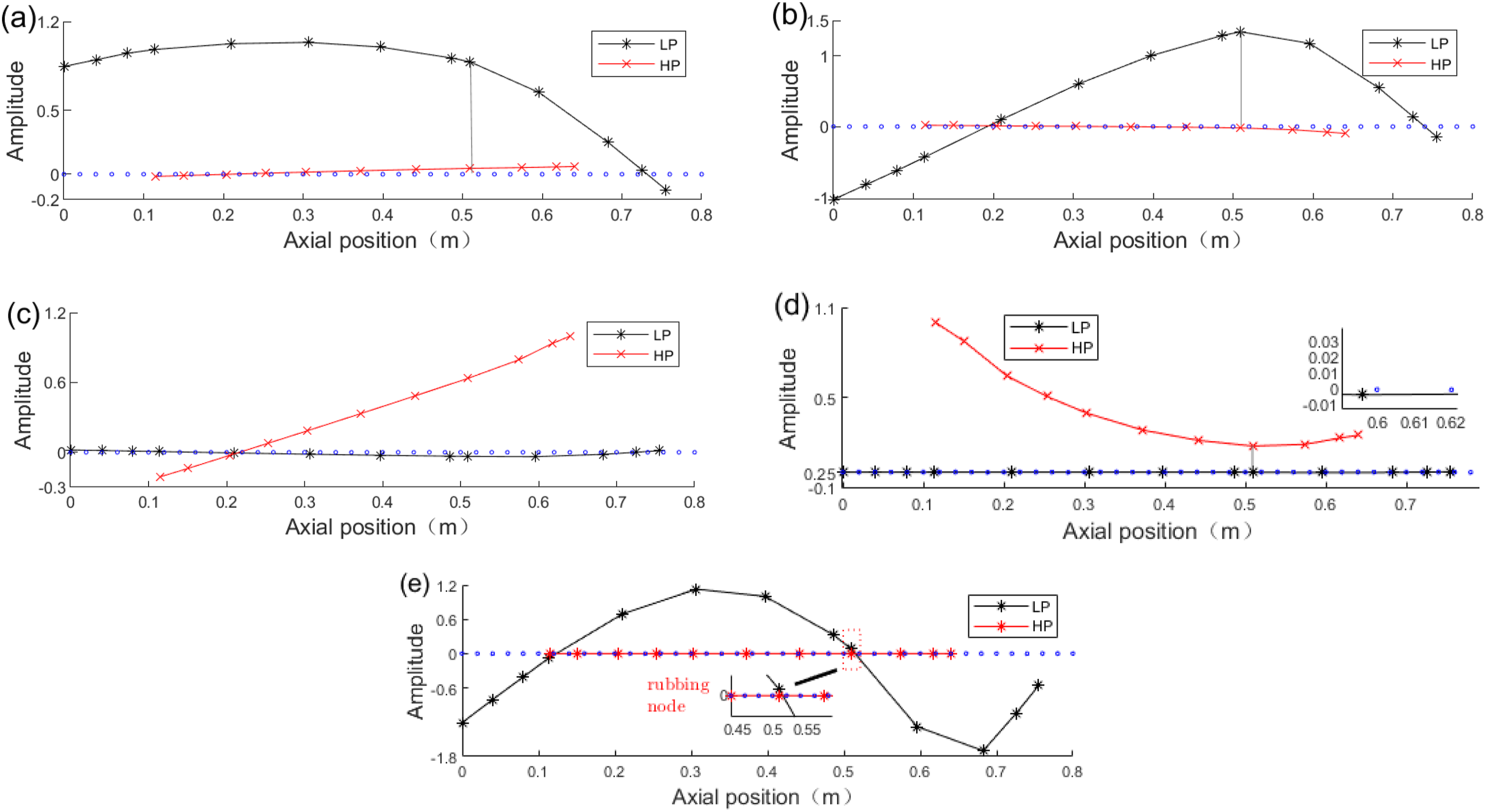
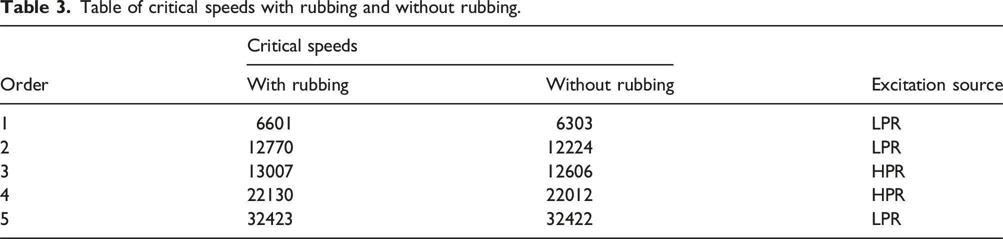
It can be found from Figure 7 that the rotor mode shapes correspond to the n = 1+-5+modes shown in Figure 5. Moreover, the vibration of the LPR can be excited by HPR as exhibited in Figure 7(c) and (d). The LPR vibration is transmitted to the HPR and induces it to generate weak vibration as shown in Figure 7(a) and (b). These phenomena show that the energy of one shaft can be transferred to the other shaft by inter-shaft rub-impact. Compared the critical speeds with and without rubbing in Table 2, it is found that the rotor critical speeds increase due to inter-shaft rub-impact. This result originates from the fact that the introduction of the support stiffness at the rubbing point improves the system stiffness. It is observed that the critical speed increase of the LPR third-order FW critical speed is not obvious. Combining with Figures 5 and 7, this phenomenon appears because rubbing node of LPR is located at the vibration node as shown in Figure 7(e), which causes the poor effect of adding stiffness.
Bifurcation and nonlinear response analysis
In this section, the dual-rotor system nonlinear characteristics with inter-shaft rub-impact are conducted. The governing equation based on the equation (17) derived in section 2 is implemented in MATLAB and solved by the Newmark-β method. The optimal calculation results and the convergence of equation iteration are ensured by setting
The radial displacement at rubbing section can be used to distinguish the rubbing types according to the rubbing force mechanical expression given by equation (14). The variation curves of radial displacement maximum values The relative displacement of rubbing nodes for 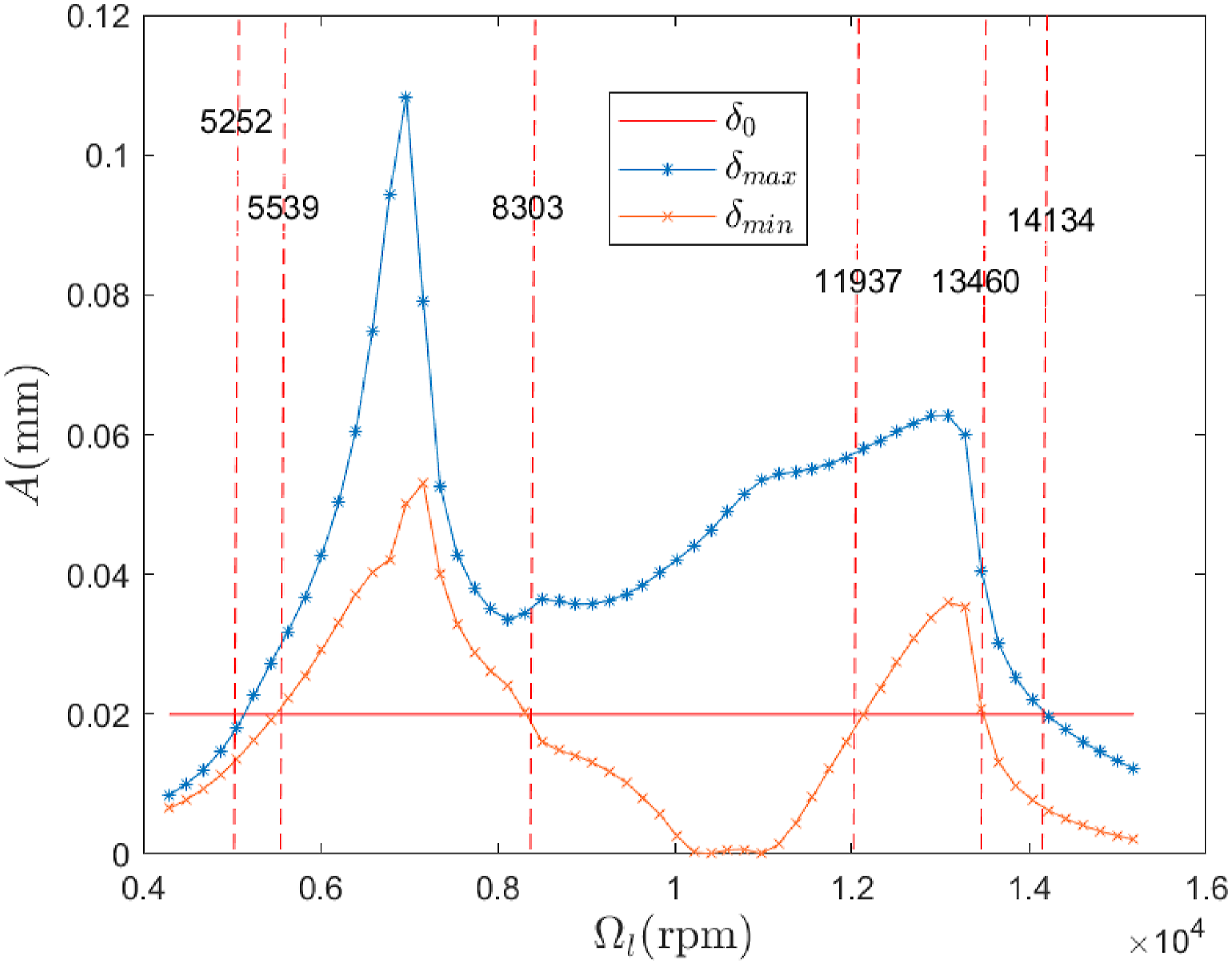
As shown in Figure 8, continuous rub-impact occurs when 5539 rpm<
The bifurcation diagram and three-dimensional spectrum of bending and torsional deformations for disk 4, are obtained as shown in Figure 9. It can be seen from Figure 9(a) that the nonlinear characteristic of disk 4 varies with the rotating speed. When Dual-rotor system dynamic response for 
According to the phenomenon shown in Figure 9(b), there are obvious frequencies
To further reveal the nonlinear responses of inter-shaft rub-impact, the axis orbit, time-domain waveform, lateral frequency spectrum, Poincare map of disk 4 lateral displacement, Poincare map of LPR torsion angle, and rubbing force at different speeds are obtained as shown in Figure 10. The rotor whirl status could be judged by comparing the order of the red point, corresponding to vibration at time Response of disk 4 at different rotation speeds for 
It can be seen from Figure 10(a) that the whirl orbit is regular and waveform approximates harmonic curves, and rotation frequencies
According to the simulation results above, it can be seen that the system response experiences period-five motion and quasi-periodic motion in the speed region 5252 rpm<
Effect of friction coefficient
In this section, the research conducted focused on the role of the friction coefficient on the dual-rotor system dynamic properties, the displacement curve, bifurcation diagram, and three-dimensional spectrum under friction coefficient The relative displacement of rubbing nodes for Dual-rotor system dynamic response for 
As shown in Figures 8 and 11, there is no fundamental difference in rubbing types and discipline of change exhibited by two diagrams. A noticeable discrepancy is that the maximum
Compared with Figure 9(a), it can be found from Figure 12 that the system response evolution process is approximately similar to that of
It can be observed from Figure 12(b) that the rotors rotation frequencies
To evaluate the effect of the friction coefficient in-depth, the axis orbit, time-domain waveform, lateral frequency spectrum, Poincare map of disk 4 lateral displacement Poincare map of LPR torsion angle, and rubbing force are obtained as shown in Figure 13. At Response of disk 4 at different rotation speeds for 
Effect of elastic modulus of the coating painted on seal
According to equation (13), the materials of coatings painted on HPR will significantly affect its stiffness and further affect the rub-impact response. For The relative displacement of rubbing nodes for Dual-rotor system dynamic response for 
Compared with Figure 11, when the elastic modulus increases under the same friction coefficient, the rubbing types remain similar; thus, intermittent rub-impact and continuous rub-impact appear alternately. However, there are obvious differences between two diagrams in speed region of rubbing motion. The dual-rotor system first enters continuous rubbing at
As shown in Figure 15, the dual-rotor system nonlinear characteristics become more apparent. At
From the simulation results, we can see that abundant combined frequencies occur in Figure 15(b), including
To further explore the dual-rotor system nonlinear characteristics, the axis orbit, time-domain waveform, lateral frequency spectrum, Poincare map of disk 4 lateral displacement Poincare map of LPR torsion angle, and rubbing force are extracted. It can be seen from Figure 16(a) that a circle consisting of five intersecting curves appears in the axis orbit, and five points appear in Poincare diagram, indicating that the rotor of LPR is 5T-periodic motion. At Response of disk 4 at different rotation speed for 
Conclusion
In this study, based on the Timoshenko beam element model including torsional degrees of freedom, the dual-rotor system dynamics model under nonlinear inter-shaft rubbing force has been established by FEM after a series of simplifications. Considering the limitation of the point impact model in analyzing cylindrical contact, the cylindrical contact model and the Coulomb model are used to form the expression of rub-impact force. The dual-rotor system dynamic equation has been numerically solved using the Newmark-β method. The Campbell diagram, modal shape, three-dimensional spectrum, whirl orbit, etc., have been obtained according to the simulation results under different rubbing parameters. Then, the rotor system nonlinear dynamic behaviors have been investigated. Some conclusions are summarized and listed as follows: (1) The inter-shaft rub-impact has a positive effect on the increase of critical speed and will lead to the coupled vibration of the rotors according to the comparison results of the Campbell diagrams and the mode shapes. Meanwhile, the LPR/HPR vibration can be excited by the vibration of HPR/LPR, which reveals the behavior of energy transfer between the two rotors by inter-shaft rub-impact. (2) It can be concluded from the displacement diagrams that when the dual-rotor system suffers from inter-shaft rubbing force, the intermittent rub-impact motion, and continuous rub-impact can be observed. (3) A more unstable system motion form will be emerged under higher friction coefficient and higher coating elastic modulus. As the rotation speed gradually increases in a certain range, the typical nonlinear dynamic behaviors including multi-periodic, quasi-periodic, and chaotic motions are revealed. Moreover, the periodicity of the system always corresponds to specific rubbing state and characteristic frequencies. (4) The characteristic frequency of torsional vibration is not exactly likely that of bending vibration, and they can be combined with each other for inter-shaft rub-impact fault diagnosis. And the torsional vibration shows the same periodic motion characteristics with the lateral vibration. (5) The friction coefficient and rubbing stiffness can significantly affect the dual-rotor system response, including stimulating the reverse whirling state and making the rub-impact responses complicated. Many frequencies can be observed in three-dimensional spectrums including rotation frequencies, natural frequency, and combination frequencies.
Highlights
• Inter-shaft rub-impact will occur due to the use of sealing structures. • The FEM model of dual-rotor system is established based on the Timoshenko beam considering torsional deformations. • The nonlinear cylindrical collision model is applied to describe the impact forces. • The coupled bending-torsional vibration responses of the dual-rotor system with inter-shaft rub-impact are investigated.
Footnotes
Declaration of conflicting interests
The author(s) declared no potential conflicts of interest with respect to the research, authorship, and/or publication of this article.
Funding
This work has been carried out with the supports of the National Science and Technology Major Project (J2019-II-0011-0031) and the National Science and Technology Major Project (J2019-II-0016-0037).