
Abstract
The ballastless track structure is the main structure of urban rail transit, and the ballastless track has the advantages of high smoothness, high stability, and less maintenance. At present, urban rail transit requires high smoothness and convenient construction of track structure and also puts forward comprehensive requirements for vibration and noise reduction. This paper intends to combine particle damping fasteners with prefabricated track structure and analyze its comprehensive effect on inhibiting environmental vibration and wheel-rail noise while taking into account the characteristics of high smoothness and convenient construction and maintenance of track. The vibration and noise reduction are mainly achieved through the particle damping fastener system, while the prefabricated track primarily serves as a structural carrier for the particle damping fastener system, and mainly provides smooth performance, good constructability, and ease of maintenance. First, simulation models of typical metro vehicles, prefabricated assembled ballastless track with particle damping fasteners, and tunnel-earth environmental vibration characteristics are established. At the same time, a wheel-rail noise simulation model considering the above track characteristics is established. Based on the above two models, the vibration and noise reduction characteristics of preassembled ballastless track structure with particle damping fasteners are analyzed comprehensively. Through the research of track structure parameters, the comprehensive effect of vibration reduction of 9 dB and noise reduction of about 1.6 dB can be achieved. The research in this paper can provide reference for the comprehensive consideration of the smoothness, convenience, comfort, and environmental friendliness of the rail structure of urban rail transit.
Keywords
Introduction
With the rapid development of the rail transit industry, by the end of 2023, the global urban rail transit network had reached 43,400.40 km, with metro systems accounting for 21,732.66 km across 200 cities in 63 countries and regions. The metro system has become the dominant mode of urban rail transit worldwide. As a major component of urban rail transit, metro systems play a crucial role in urban underground space utilization, offering advantages such as alleviating urban traffic congestion, high operational safety, large passenger capacity, and economic efficiency. 1 Metro systems have significantly eased traffic congestion in medium and large cities, expanded urban spaces, optimized urban functional layouts and spatial structures, and improved residents’ quality of life. 2
However, the rapid expansion of metro networks has also led to deterioration in track conditions, exacerbation of wheel-rail interactions, increased track irregularities, intensified wheel-rail vibrations, and higher dynamic loads. Under the excitation of wheel-rail irregularities, the vehicle-track system inevitably generates vibrations. 3 Moreover, metro vehicles induce environmental vibrations and vibration-related noise, which can disrupt the daily lives of residents along the railway corridors. Studies have shown that metro-induced vibration noise negatively affects human physiological functions, impacting the nervous system, muscles, and skeletal structures, leading to various adverse physiological reactions. 4 Consequently, metro-induced noise pollution significantly affects work, daily life, and sleep patterns. Thus, it is crucial to investigate the formation mechanisms and influencing factors of metro vehicle noise and develop effective mitigation measures.
With the increasing application of particle damping, this paper will combine particle damping and fastener system to carry out comprehensive research on vibration and noise reduction. The following will review the literature from two aspects of track/fastener parameters and particle damping.
About track/fastener parameters, extensive research has been conducted on the damping mechanisms and performance of track fasteners. Wu and Thompson 5 compared variable stiffness, low-stiffness, and high-stiffness fasteners in terms of their rail vertical vibration response and attenuation rates, concluding that higher fastener stiffness significantly enhances vibration attenuation. Li 6 investigated the impact of fastener stiffness on in-car noise and found that reducing fastener stiffness increases rail vibrations, leading to higher interior noise levels. Song et al. 7 developed a vertical dynamic model of the vehicle-track system, incorporating rail pad support, to analyze the effects of rail pad stiffness on wheel-rail forces. Their results demonstrated that optimizing rail pad stiffness can effectively mitigate vibrations. These findings collectively indicate that the parameters of the rail-track slab connection device have a significant impact on the vibration and noise of the vehicle-track system. Therefore, improving the structural design of fasteners is a feasible approach to reducing metro-induced vibration and noise.
About particle damping, Masri8,9 conducted early theoretical studies on the impact damping mechanism, deriving analytical solutions for the steady-state vibration of structures equipped with single-cell and multi-cell particle impact dampers under periodic excitation and analyzing their motion stability. Panossian 10 experimentally investigated the damping effects of obstructed particle dampers on aluminum beams, revealing that filling the beam with tungsten, steel, and zirconia powders significantly improved structural damping. Michon and Guilhem 11 studied inelastic collisions between particles and structures in the vertical vibration direction, further elucidating the underlying damping mechanisms. In China, research on particle damping technology started relatively late. Zhang et al. 12 explored the optimal particle motion modes in particle dampers, evaluating their effective mass and damping characteristics. Xiao et al.13,14 incorporated particle dampers into high-speed gears, analyzing the effects of particle parameters on vibration reduction and further examining the energy dissipation mechanisms of particle dampers in a centrifugal field. Liao et al. 15 studied on the energy dissipation mechanism of dynamic mechanical systems with particle dampers by using the novel energy method. Li et al. 16 studied the performance of tuned mass particle dampers and elucidated the relationship between damping effectiveness and energy dissipation mechanisms. These studies indicate that particle dampers have been increasingly applied across various fields, and research interest in this area continues to grow. However, most existing studies focus on the energy dissipation, damping performance, and amplitude attenuation of particle dampers themselves. Research on the comprehensive vibration and noise reduction effects of particle dampers integrated into the entire metro vehicle-track system remains limited.
Conventional vibration mitigation measures often struggle to achieve both vibration and noise reduction simultaneously. For example, traditional vibration-reducing fasteners achieve effective environmental vibration mitigation by reducing fastener stiffness, but this comes at the cost of amplifying wheel-rail noise and potentially worsening rail surface conditions. Therefore, this paper intends to combine particle damping fasteners with prefabricated track structure and analyze its comprehensive effect on inhibiting environmental vibration and wheel-rail noise while taking into account the characteristics of high smoothness and convenient construction and maintenance of track. In the following sections, the ballastless track structure with particle damping fastener prefabricated is introduced, and the particle damping fastener model is established based on discrete element method and tested. Simulation models of typical metro vehicles, prefabricated assembled ballastless track with particle damping fasteners, and tunnel-earth environmental vibration characteristics are established. Environmental vibration characteristics and damping effect are analyzed. A wheel-rail noise simulation model considering the above track characteristics is established. Wheel-rail noise characteristics and noise reduction effect are analyzed. Finally, the vibration and noise reduction characteristics of preassembled ballastless track structure with particle damping fasteners are summarized comprehensively in Section 5.
Structure and modeling of particle damping fastener systems coupled with prefabricated assembled ballastless track
Structure introduction
Overall structure of prefabricated assembled ballastless track
The prefabricated assembled ballastless track structure (Figure 1) adopts two prefabricated track slabs to support the rail, and the track slabs are joined into the whole track bed by in situ concrete. This track structure can have both the smooth performance of the slab ballastless track and the good constructability and maintenance performance of the double-block ballastless track in the tunnel. The upper part can flexibly adopt the fastening system with both vibration and noise reduction performance to meet the increasing comprehensive demand for vibration and noise reduction. Schematic diagram of overall structure of prefabricated assembled ballastless track.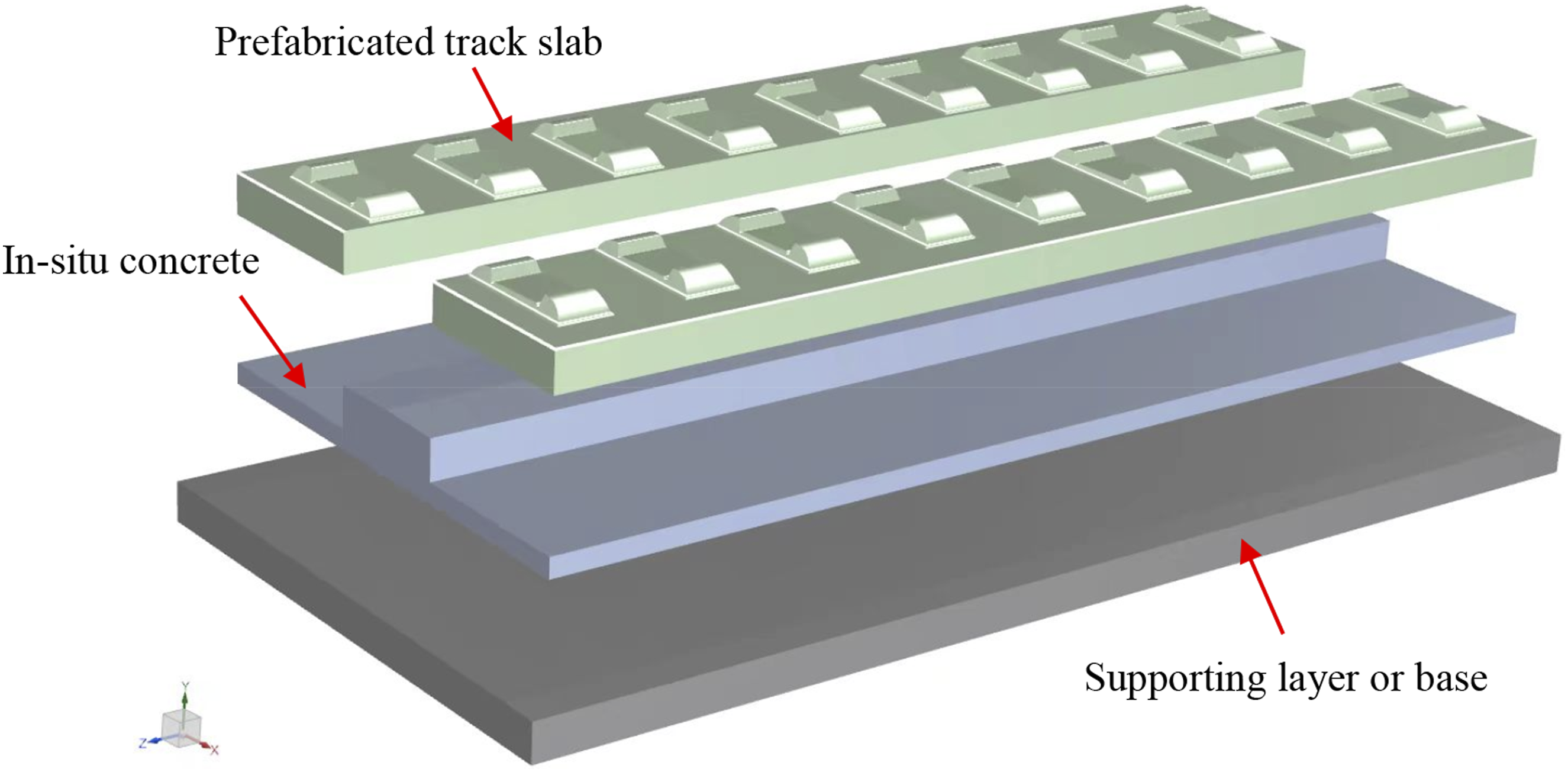
Structure of particle damping fastener system
The structure of particle damping fastener systems is shown in Figure 2. Two particle dampers were designed, positioned at the rail web and under the rail, respectively. Additionally, a fixture for the rail web damper was incorporated, and the iron backing plate structure was redesigned. Schematic diagram of the structure of particle damping fastener system.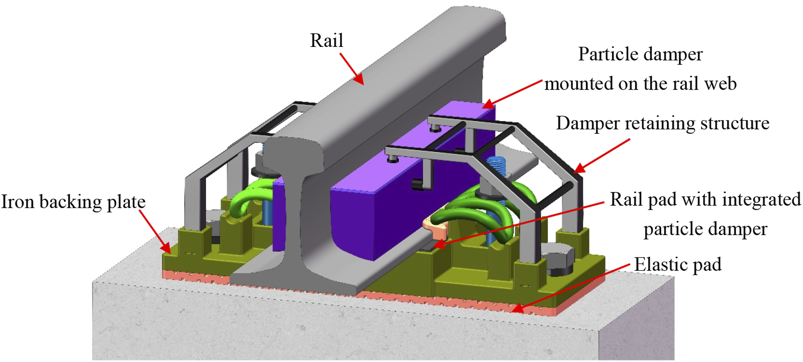
Rail pad with integrated particle damper
The detail structure of the rail pad with integrated particle damper is shown in Figure 3. The particle damper consists of a cavity, a cover plate, and damping particles. The cover plate is fitted to the cavity using a snap-fit mechanism, which reduces the number of bolts and other fasteners required for the overall fastening system. Due to the lateral and longitudinal constraints imposed by the rail pad, the dimensions of the particle damper in these directions are limited, while its vertical height offers a relatively larger range of variability. The external dimensions of the under-rail damper are 169 × 169 × 25 mm, and it is constructed using steel material. Rail pad with integrated particle damper: (a) Cross-sectional view and (b) structural appearance.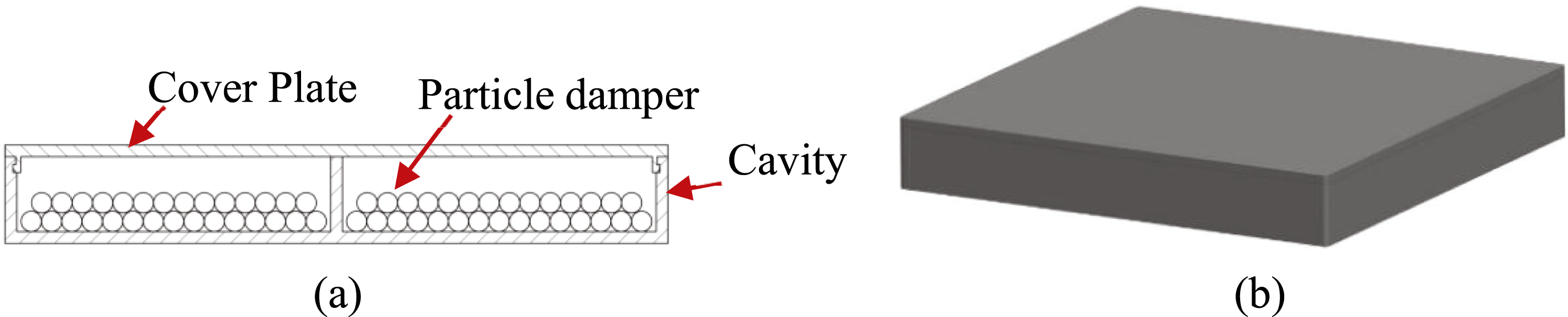
Particle damper mounted on the rail web and retaining structure
Figure 4 shows the detail structure of the particle damper mounted on the rail web. The composition of this damper is similar to that of the rail pad with integrated particle damper. But unlike the rail pad, the particle damper mounted on the rail web does not bear the load of the rail, allowing for the removal of reinforcement ribs to increase the volume available for granular filling. Additionally, circular holes are designed at the top of the cover plate for fastening and installation. The structure is made entirely of steel. Particle damper mounted on the rail web.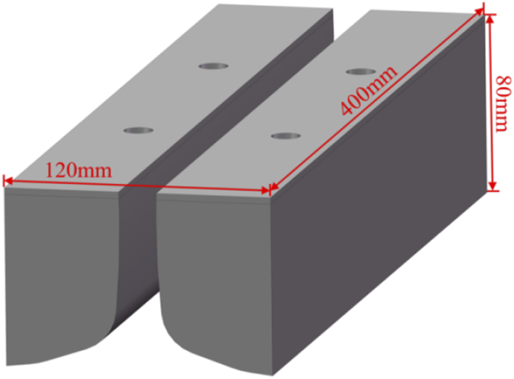
Figure 5 shows the retaining structure for the particle damper mounted on the rail web, which consists of a support frame, springs, and rubber sleeves. The support frame is connected to the iron backing plate via clips at its base. Its function is to ensure precise positioning between the particle damper mounted on the rail web and the iron backing plate, thereby maintaining the stability and reliability of the assembly. Damper retaining structure.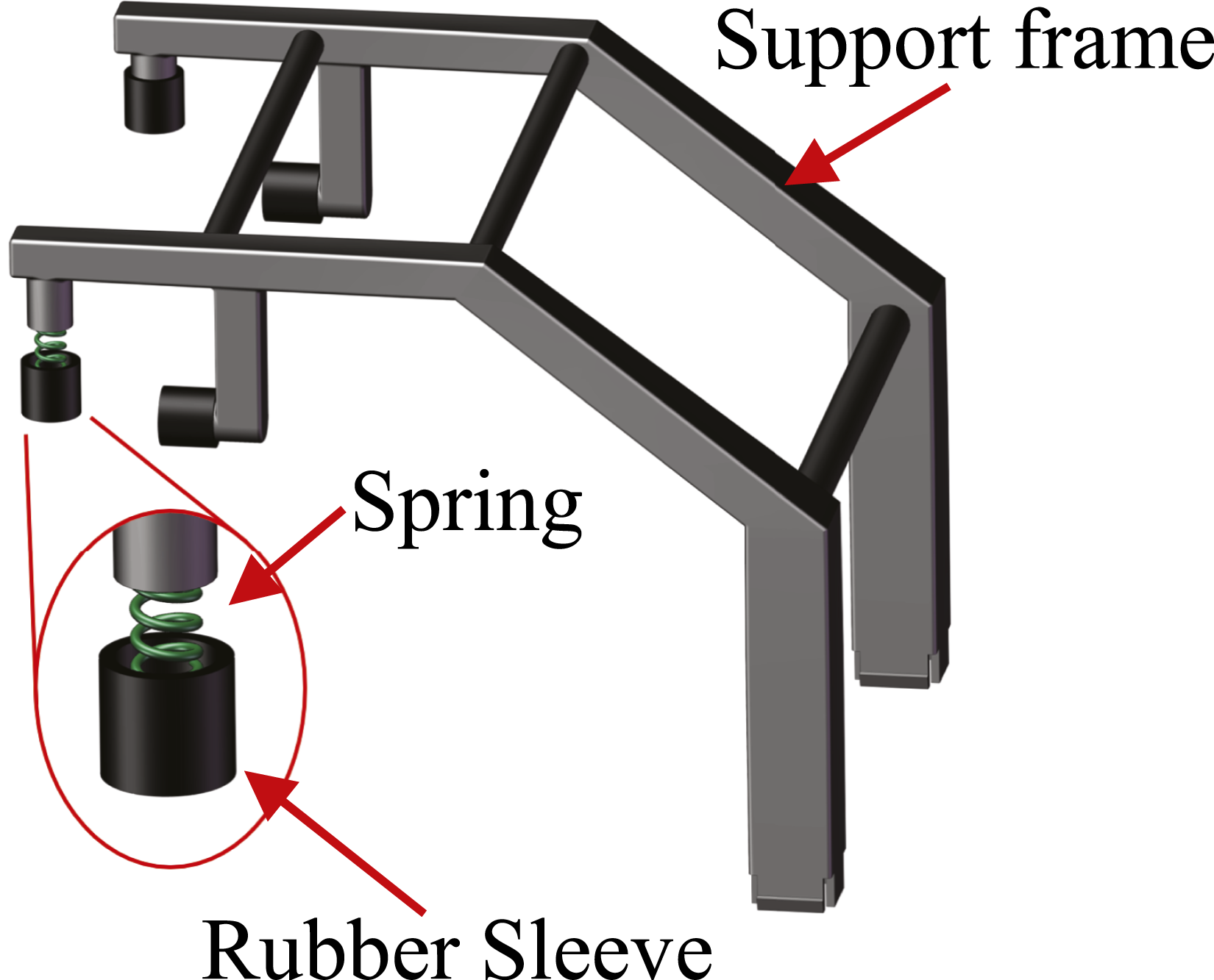
Engineering applicability analysis
Manufacturability and ease of installation
The proposed particle damping module is an independently prefabricated, enclosed metal cavity that can be integrated with the fastening base structure via bolts or snap-fit connectors, without altering the basic rail-to-sleeper connection form. The module can be manufactured using standard metal casting or stamping techniques, requiring no high-precision machining, thus offering good manufacturability. The modular design also facilitates rapid on-site installation and replacement, improving construction efficiency.
Long-term performance and particle migration
To prevent particle migration, compaction, or leakage under long-term vibration, a sealed cavity structure is employed, with elastic liners installed at the structural boundaries to enhance dynamic dispersion of the internal particles. Additionally, particles with rough surfaces or irregular shapes (e.g., irregular lead alloy granules) can be selected to increase internal friction and mixing stability, reducing the risk of migration.
Particle leakage and environmental impact
The cavity is hermetically sealed using weathering steel or corrosion-resistant aluminum alloy materials to ensure no particle leakage during its service life. For harsh outdoor environments involving high temperatures, humidity, or dust, protective coatings or cladding can be applied to the exterior of the cavity. Drainage holes are also designed to prevent condensation and water accumulation. With proper sealing, the system avoids environmental contamination caused by particle leakage.
Performance degradation of particles over time
According to previous experimental studies on the long-term stability of dry particle dampers,17,18 as long as the cavity structure remains sealed and stable, the damping performance of particles shows minimal degradation over millions of vibration cycles. In practical applications, a scheduled maintenance interval of 3 to 5 years is recommended, which is significantly longer than the typical maintenance cycle for railway fasteners.
Maintenance impact and replaceability
The particle damping module is designed to be replaceable independently from the rest of the fastening system. During maintenance, only the particle module needs to be replaced, ensuring good feasibility in engineering maintenance. We also suggest incorporating the particle cavity into the fastening system’s condition monitoring plan, using vibration-acoustic responses or changes in cavity weight as indicators for maintenance.
Modeling of particle damping fastener based on discrete element method
The particle damper dissipates vibrational energy through collisions and friction between the particles and between the particles and the cavity walls, thereby suppressing vibration-induced noise. The unique damping mechanism exhibits high nonlinearity. Among the methods used to study granular dampers, the most applied is the discrete element method (DEM), where the contact model plays a central role. The Hertz-Mindlin nonlinear contact model 19 is frequently used in granular damping, as it offers more complex and accurate calculations compared to linear contact models. The DEM-based particle damping model is established under the following assumptions: (1) Particle shape is assumed to be ideally spherical. The particles used in this study are circular in shape, making this DEM assumption reasonable. (2) The particle contact model adopts the classical Hertz-Mindlin nonlinear contact model, which is widely used in dry particle systems. It accounts for normal elastic force, tangential friction force, and viscous damping. Since the particle damping devices considered in this study also involve dry particles, this DEM assumption is deemed appropriate. (3) Damping and energy dissipation mechanisms are assumed to arise from contact damping during collisions, with particle breakage not considered. The energy dissipation in the particle damping studied here primarily results from collision-induced energy loss, consistent with the DEM assumption. Moreover, the particles used are metallic and highly resistant to breakage during actual use, further validating the reasonableness of this DEM assumption.
As shown in Figure 6, k
n
represents the normal contact stiffness of the particles; C
n
is the normal damping coefficient; k
t
is the tangential contact stiffness of the particles; C
t
is the tangential damping coefficient; and μ is the coefficient of static friction. Discrete element contact model.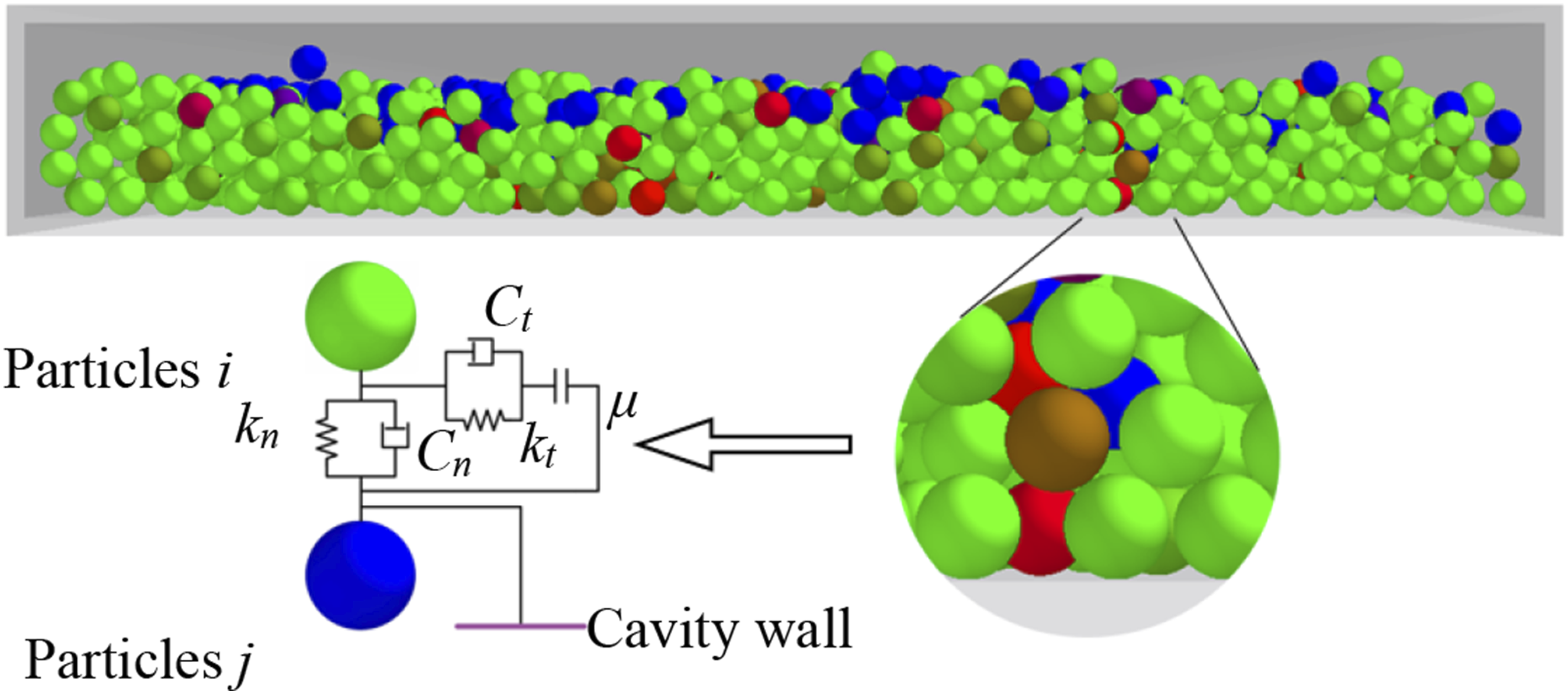
According to Hertzian contact theory, the normal contact stiffness k
n
and k
t
tangential contact stiffness of the particles can be expressed as follows
20


When a particle contacts the cavity, the cavity is treated as a particle with an infinitely large radius and a velocity of zero.
The normal damping C
n
and tangential damping C
t
of the particles can be expressed as follows:


The normal contact force F
n
between particles can be expressed as follows:

When no relative sliding occurs, the tangential contact force Ft between particles is expressed as follows:

When relative sliding occurs, the inter-particle tangential force Ft is expressed as follows:

The acceleration


Based on the EDM, the particle damper mounted on the rail web and rail pad are simplified into a single closed cavity, and a discrete element model was established, as shown in Figure 7(a), and a single degree of freedom system dynamics model was established, as shown in Figure 7(b), and the two are jointly simulated to complete the fastener system model. Model of particle damping fastener system: (a) Discrete element model and (b) kinetic model.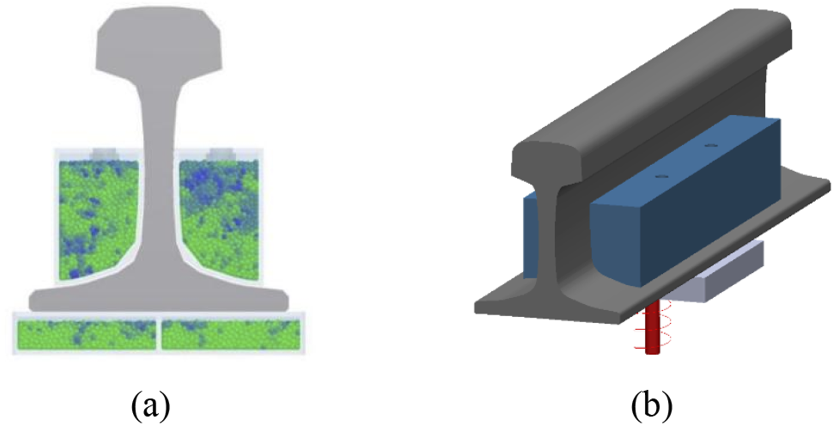
Experimental verification
A prototype (0.3 m in length) was fabricated based on the developed granular damping fastener system, and frequency response function (FRF) tests were conducted to evaluate and verify the damping performance of the system. The damping performance was assessed by measuring the frequency response function of the fastener system. During the experiment, only the rail web particle dampers were installed. Both sides of damper on rail web are filled with 4000 steel balls with a diameter of 4 mm, with a filling rate of 20%. A photograph of the experimental setup is shown in Figure 8. The experiment employed a B&K 8210 type force hammer as the excitation source, and the accelerometer was positioned at the center of the railhead. Experimental setup of particle damping fastener system: (a) B&K 8210 type force hammer and (b) photograph of the test setup.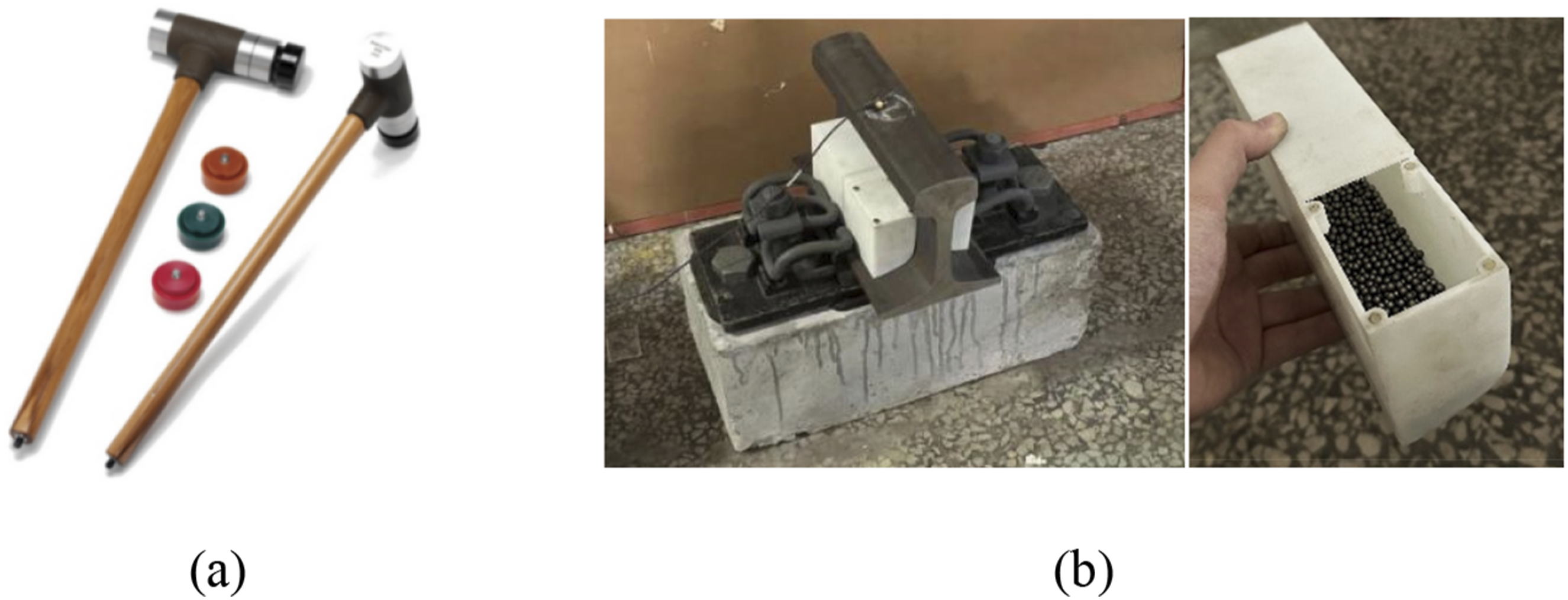
The experimental results of the FRF are shown in Figure 9. According to the simulation results, the damping ratio of the fastener system with the rail web damper installed is 0.0735, representing a 15% improvement as calculated using the half-power bandwidth method. When compared with the experimental results, the error is within 2%, indicating that the simulation model and parameter selection are reasonable in terms of the observed improvement in system damping ratio. Comparison of experimental and simulation results of particle damping fastener system.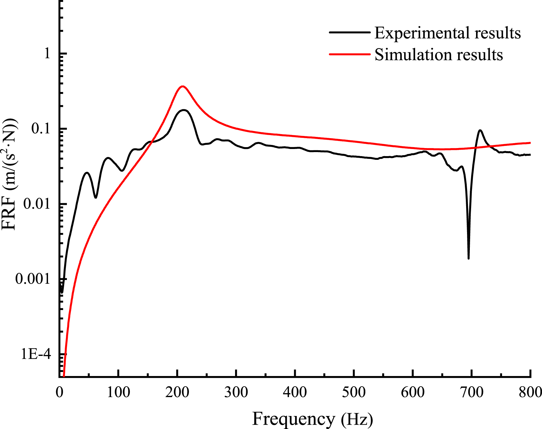
Damping characteristics
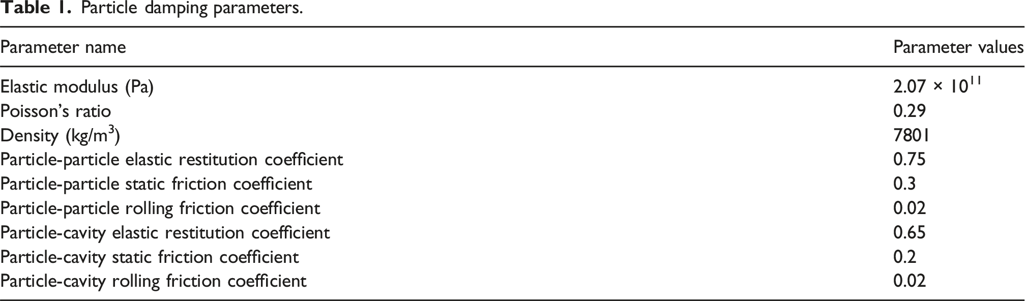
Particle damping parameters.
According to the vibration-damping mechanism of particle dampers, friction and collisions between particles, as well as between particles and the cavity, are the primary energy dissipation methods. When the particle filling rate is too low, there are too few particles involved in friction and collisions, resulting in limited energy dissipation. Conversely, when the particle filling rate is too high, the movement space of the particles is restricted, preventing sufficient friction and collisions for effective energy dissipation. To preliminarily explore the impact of particle filling rates on the damping performance of the new fastening system, particle mass filling rates of 20%, 40%, 60%, 80%, and 100% were set. The models of the under-rail particle dampers under different filling rates are shown in Figure 10. Models of the under-rail particle dampers under different filling rates: (a) 20%; (b) 40%; (c) 60%; (d) 80%; and (e) 100%.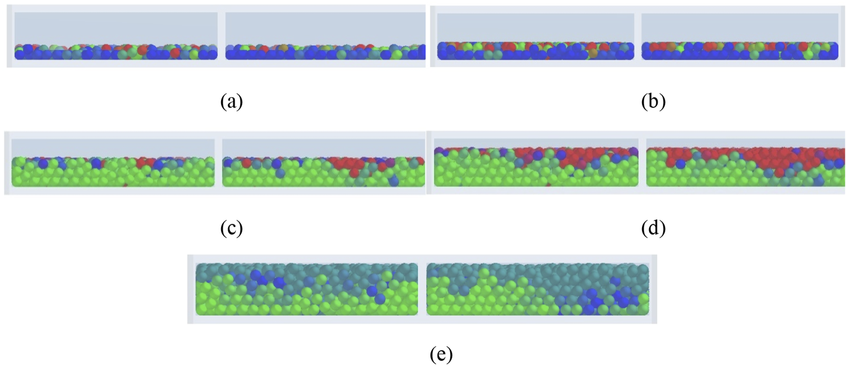
Figure 11 shows the time-domain attenuation curves of rail vertical displacement under different particle filling rates, with the simulation duration set to 0.2 s. Figure 11(b) is a localized magnification of Figure 11(a). Time-domain attenuation curves of rail vertical displacement under different particle filling rates: (a) Entire time-domain results and (b) localized magnified results.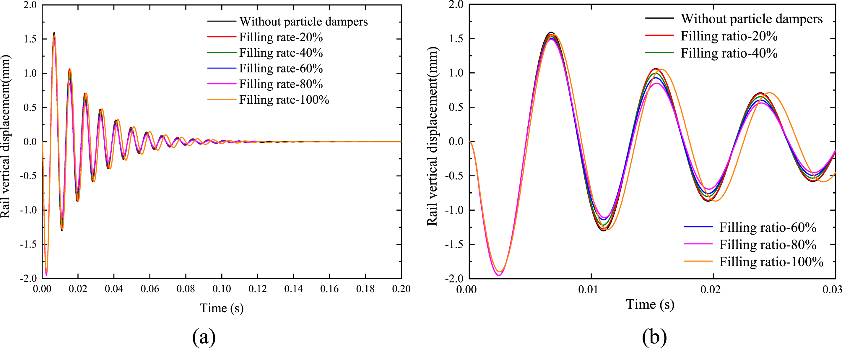
As shown in Figure 11, the rail vibration converges within 0.2 s, indicating that the simulation duration is reasonable. When the particle filling rate is between 0% and 80%, the amplitude attenuation of rail vibration increases with the particle filling rate. During this range, the rail vibration period changes slightly, suggesting that the particle motion is sufficient, resulting in effective energy dissipation. However, when the particle filling rate reaches 100%, the amplitude attenuation is weaker than that at 80%, and the rail vibration period increases. This is because an excessively high filling rate limits the space for particle friction and collisions, leading to poor energy dissipation. At this point, the under-rail particle damper essentially acts as an additional mass.
In this study, the equivalent system damping ratio of the particle damper was calculated using the half-power bandwidth method. According to the above analysis, the damping performance of the new fastening system improves as the particle filling rate increases from 0% to 80%. However, the variation pattern between 80% and 100% requires further discussion. Therefore, the following analysis adds the condition with a particle filling rate of 90%. The frequency-domain vertical acceleration of the rail under different particle filling rates is shown in Figures 12, and 13 shows damping ratio of rail fastener system under different particle filling rates. Frequency-domain vertical acceleration of rail under different particle filling rates. Damping ratio of rail fastener system under different particle filling rates.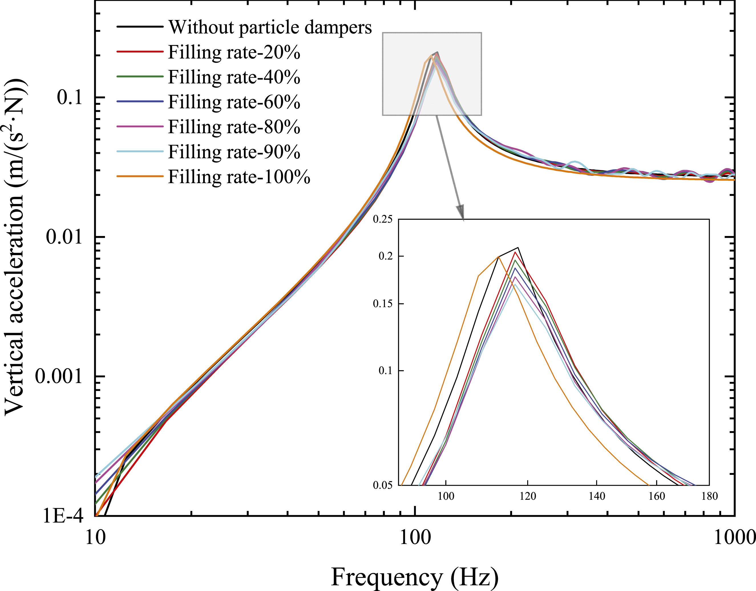
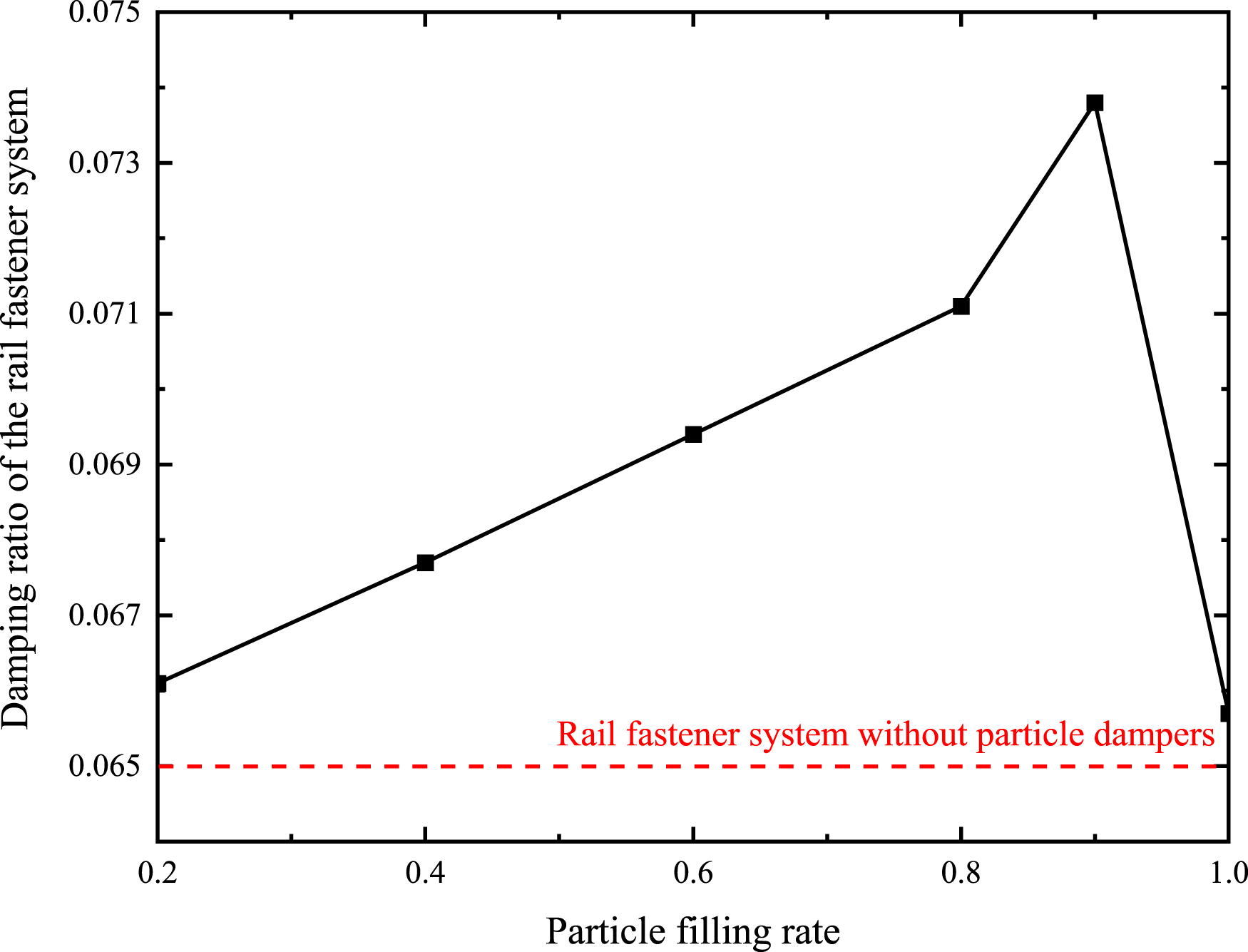
As shown in Figure 12, when the particle filling rate is 90%, the peak frequency of the rail’s vertical acceleration is similar to that observed at filling rates between 0% and 80%, but the peak value is lower, indicating that the energy dissipation effect is better at a 90% filling rate. According to Figure 13, when the particle filling rate is between 0% and 90%, the damping ratio of the particle damper increases with the particle filling rate. However, as the filling rate approaches 100%, the damping ratio decreases. At a 90% filling rate, the damping ratio of the fastening system with an under-rail particle damper is 0.0738, representing an approximately 12% increase in the damping ratio.
In addition to investigating the filling ratio, the effect of particle diameter was also examined. Particle diameters were set at 3 mm, 4 mm, and 5 mm, and the damping ratios of the fastener under different particle diameters were calculated, as shown in Figure 14. Damping ratio of rail fastener system under different particle diameter.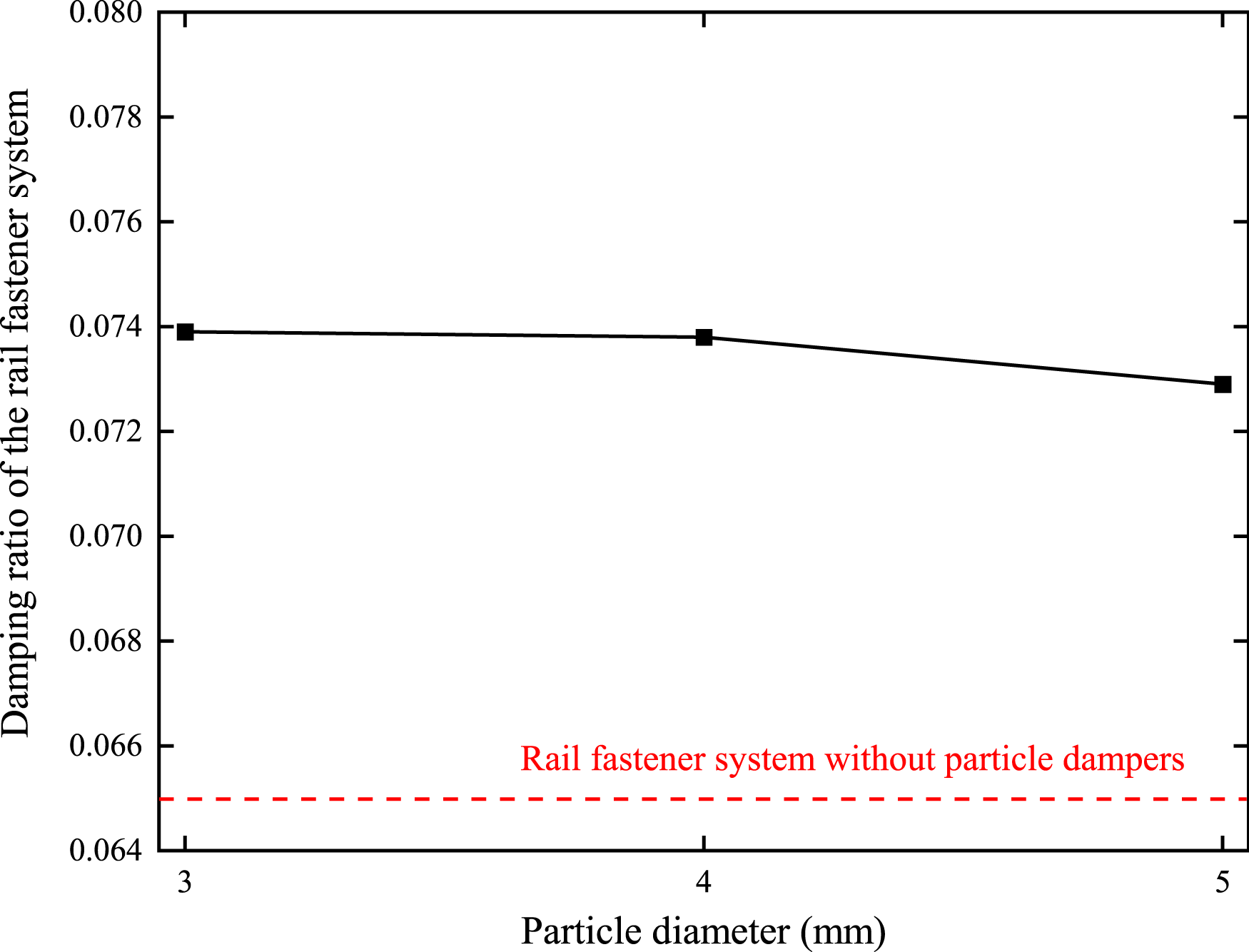
According to Figure 14, the impact of particle diameter on the damping ratio of the fastener is minimal and can be almost neglected. However, the fastener with a particle diameter of 3 mm shows a relatively higher damping ratio of 0.07, which represents a 13.7% improvement compared to a standard fastener. Therefore, this diameter should be selected in subsequent design considerations.
A wide range of materials can be used to make the filler particles, including metals, rubber, glass, ceramics, plastics, magnetorheological materials, and even liquids. This section focuses only on commonly used industrial metals: steel, aluminum, and lead. The simulation parameters for each type of particle material are also based on the 5th edition of the Mechanical Design Handbook compiled by the China Nonferrous Metals Engineering and Design Institute. The damping ratios of the fastener with different particle materials were calculated, as shown in Figure 15. Damping ratio of rail fastener system under different particle materials.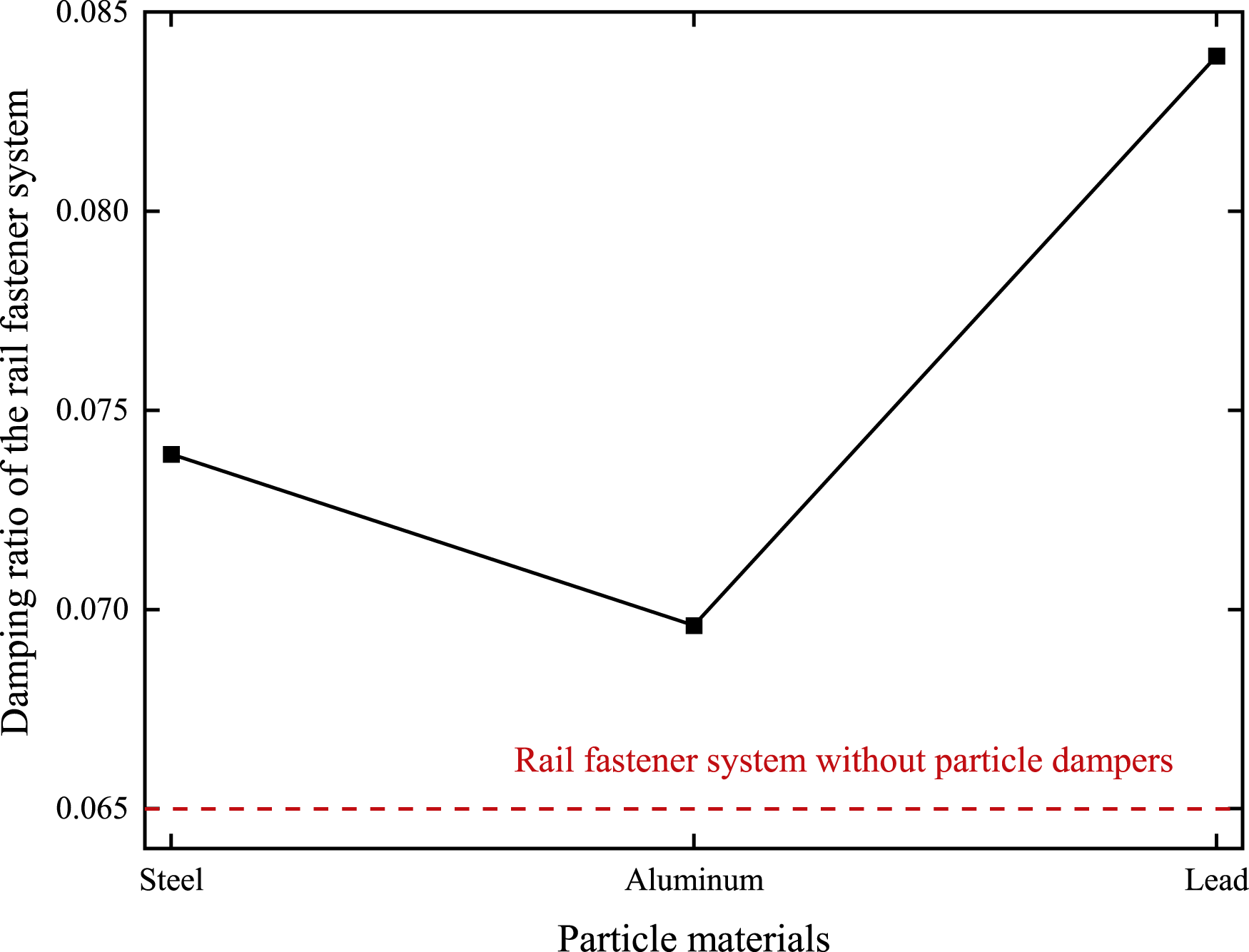
Based on the above analysis, the selected particle parameters are as follows: a filling ratio of 90%, a particle diameter of 3 mm, and lead as the particle material.
To further explore the damping characteristics of the under-rail particle damper combined with the rail web particle damper, the model was modified to include the rail web particle damper, as shown in Figure 7. The vertical acceleration of the fastening system with the additional rail web damper is shown in Figure 16, where the first-order resonance frequency of the fastener system with particle dampers is significantly lower than that of the standard fastening system. Using the half-power bandwidth method, the damping ratio considering both the under-rail and rail web particle dampers was calculated to be 0.1052, representing an approximately 62% increase in the damping ratio. Vertical acceleration of the fastening system with under-rail and rail web dampers.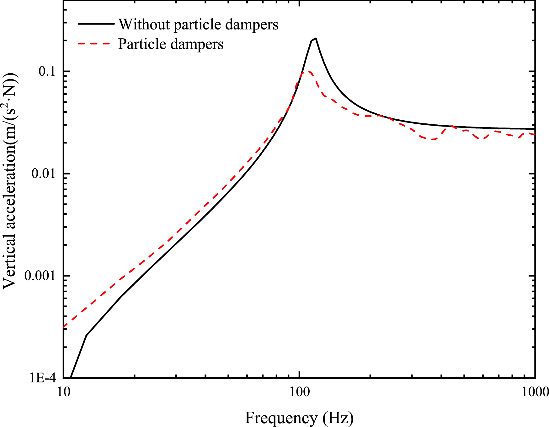
Environmental vibration characteristics and damping effect
Environmental vibration prediction model
The 2.5-dimensional finite element–boundary element method is a commonly used approach for predicting environmental vibrations and has been validated both theoretically and experimentally. In this section, the vehicle-track interaction model and the tunnel-earth 2.5-dimensional finite element–boundary element model are used to establish the environmental vibration prediction model and verify the correctness of the model.
Vertical dynamics model of multi-rigid body vehicle system
The vertical dynamics model of the multi-rigid body vehicle system proposed is established, each vehicle consists of one car body, two bogie frames, four wheelsets, and one or two series of suspensions. They are connected by damping springs.
The vibration differential equation for the vehicle system is shown in equation (10).
The wheel-rail irregularity is considered as a harmonic irregularity. When a load with a wavelength of λ is applied to the train, its circular frequency is 

By substituting equations (11) and (12) into the vehicle motion differential equation (10), the following equation is obtained:
The matrix
Ballastless track model with infinitely long period structure
Based on the theory of infinitely periodic structures, a vibration model of the ballastless slab track system is established. The rail is modeled as a Timoshenko beam, and the track slab is analyzed using the modal superposition method.
The 2.5-dimensional equation for the vibration of ballastless track rails is as follows:

Wheel-rail interaction model
The wheel-rail interaction relationship used in this study is given by the following equation:
Tunnel–ground 2.5D finite element–boundary element model
In this section, a 2.5D finite element–boundary element model is established by taking into account the longitudinally infinite extent of the tunnel and ground, the semi-infinite nature of the ground, the stratification of soil layers, and the structural characteristics of the tunnel. According to Ref. 21, the differential equations of motion of the elements are finally obtained during the construction of the prediction model:
Tunnel wall vibration is an important parameter to evaluate the environmental vibration of subway vehicles, and this paper evaluates the suppression effect on environmental vibration through the Z-weight vibration level on tunnel wall at the height of 1.2 m.
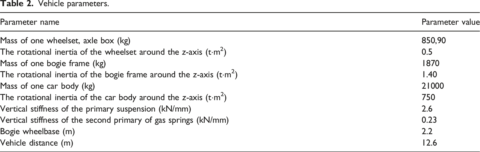
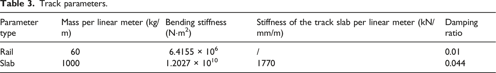
Track parameters.
Vibration characteristics and damping effect
Figure 17 shows the wheel-rail forces for conventional fastener and particle-damped fasteners with different pad stiffnesses, where the stiffness of the pad in the conventional fastener is 40 kN/mm. Figure 18 shows the corresponding Z-weighted vibration levels in the vertical direction on the tunnel wall, which are used to assess their influence on environmental vibration. Wheel-rail forces for conventional fasteners and particle-damped fasteners with different pad stiffnesses. Z-weighted vibration level of tunnel wall for conventional fasteners and particle-damped fasteners with different pad stiffnesses.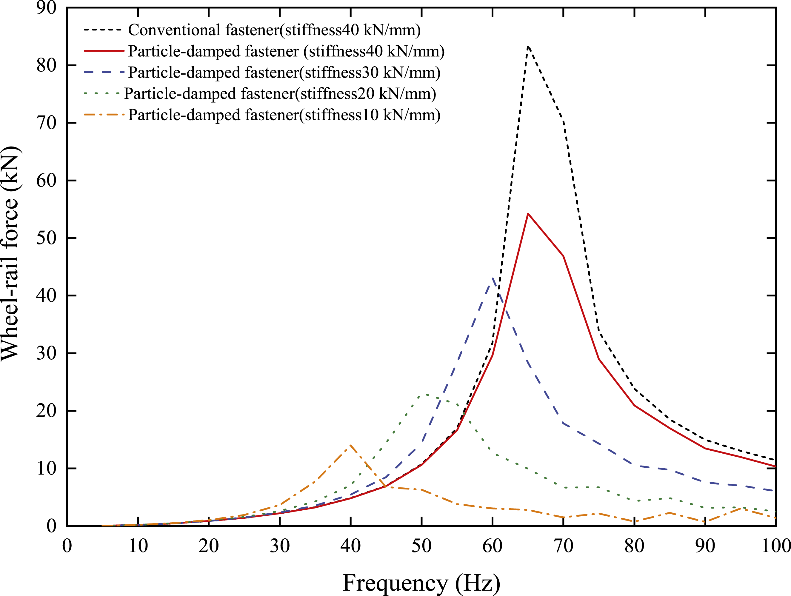
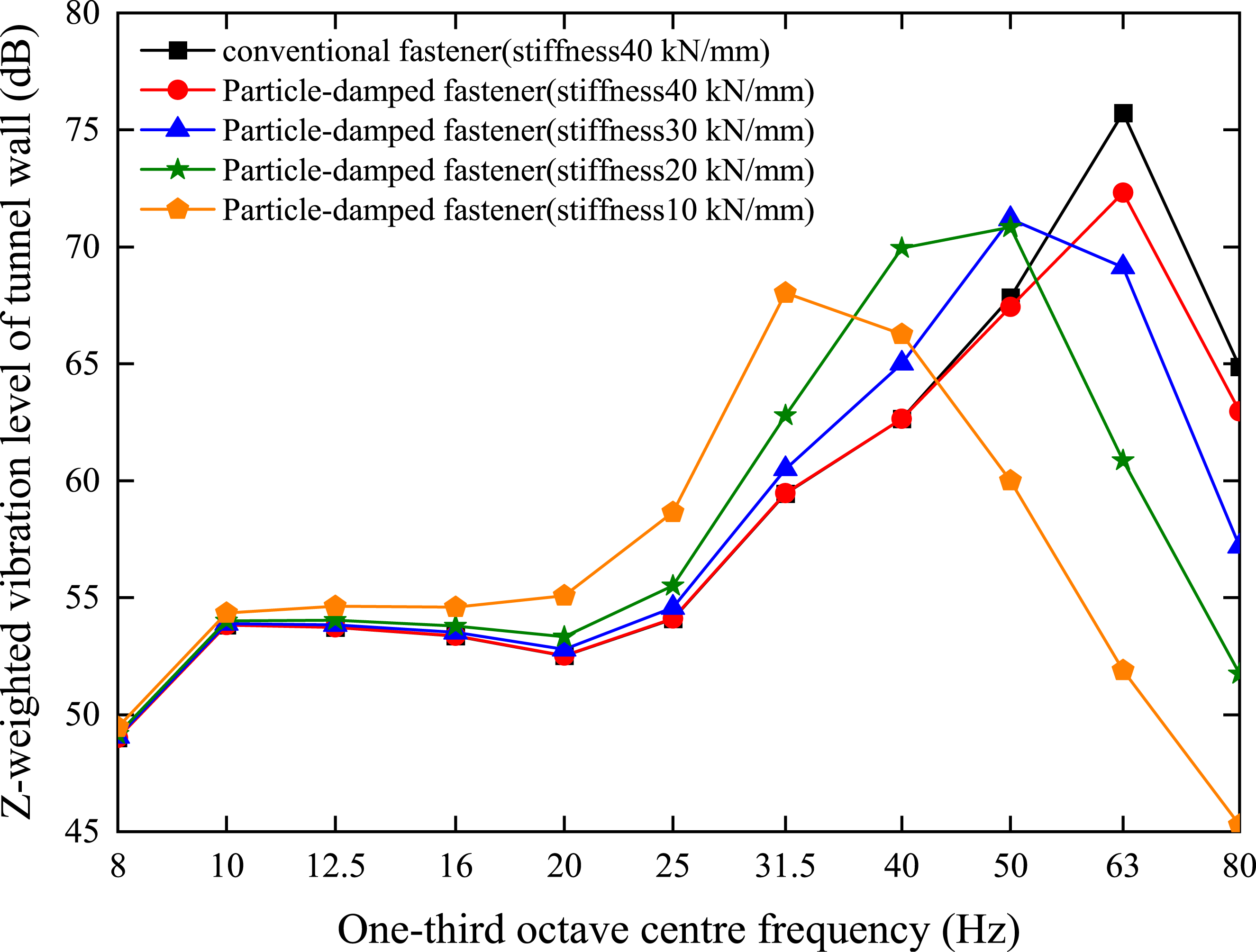
As shown in Figures 17 and 18, the vibration characteristics of the tunnel wall generally correspond to the wheel-rail forces. Under the same stiffness conditions, the particle-damped fastener results in lower wheel-rail forces and reduced tunnel wall vibration compared to the conventional fastener. For the particle-damped fastener, both the frequency and the magnitude of the peak values in the wheel-rail force and tunnel wall vibration decrease as the pad stiffness decreases. Compared with the conventional fastener, the particle-damped fastener with a pad stiffness of 40 kN/mm reduces vibration by 2.4 dB, while a stiffness of 10 kN/mm yields a reduction of 5.6 dB. This indicates that particle-damped fasteners can effectively reduce vibration under the same stiffness conditions, and that vibration mitigation can be further enhanced through the proper matching of particle damping and fastener stiffness.
Wheel-rail noise characteristics and noise reduction effect
Wheel-rail noise prediction model
A prediction model of acoustic radiation of wheel-rail structure was established to study the influence of new fasteners on the acoustic radiation of subway wheel-rail system. The influence of the spring part of the vehicle on the wheel-rail noise is small,22,23 so the analysis is not carried out, and the reduction effect of particle-damped fastener on the wheel-rail noise is studied.
Vibration and sound radiation model of wheel based on FEM-BEM
According to the mechanism of wheel-rail rolling noise generation, surface roughness excitation at the wheel-rail interface induces vibration in the wheel structure. When this vibration is transmitted to the upper components, the high-frequency components are significantly attenuated due to the effect of the vibration-isolating springs. As a result, the high-frequency vibration of the bogie is mainly dominated by the wheel. Therefore, in the analysis of high-frequency vibration in the wheel system, the model above the excitation point typically retains only the wheel, while the superstructure above the suspension is neglected. Figure 19 shows the finite element model of a typical metro train wheel. The wheel has a diameter of 840 mm and shares the same material properties as the steel described earlier. The loading position is indicated in the figure, and constraints are applied at the wheel hub. Finite element mesh of the wheel.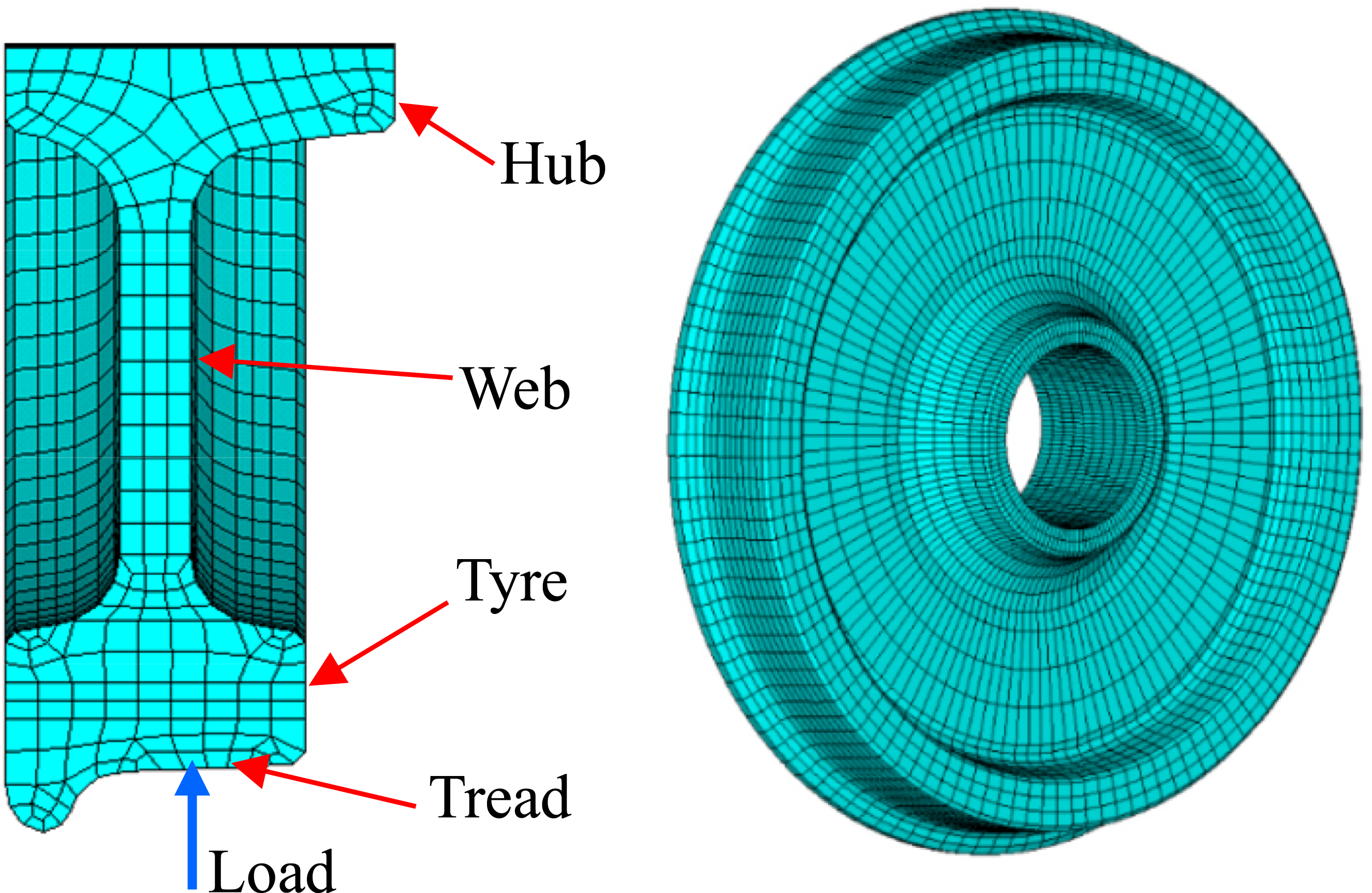
The vibration responses obtained from the wheel vibration model are used as input for the wheel boundary element model. The radiated noise of the wheel is then calculated using the acoustic boundary element method. As shown in Figure 20, to prevent sound leakage through the hub holes, additional elements are applied to seal the openings. The wheel’s acoustic radiation is computed using the direct boundary element method. In the simulation, the air density is set to 1.21 kg/m3 and the speed of sound in air is 344 m/s. The calculation covers a frequency range of 20 to 5000 Hz with a frequency step of 20 Hz. In general, for acoustic boundary element analysis, the maximum element size should be smaller than one-sixth of the shortest wavelength in the frequency range. Boundary element mesh of the wheel.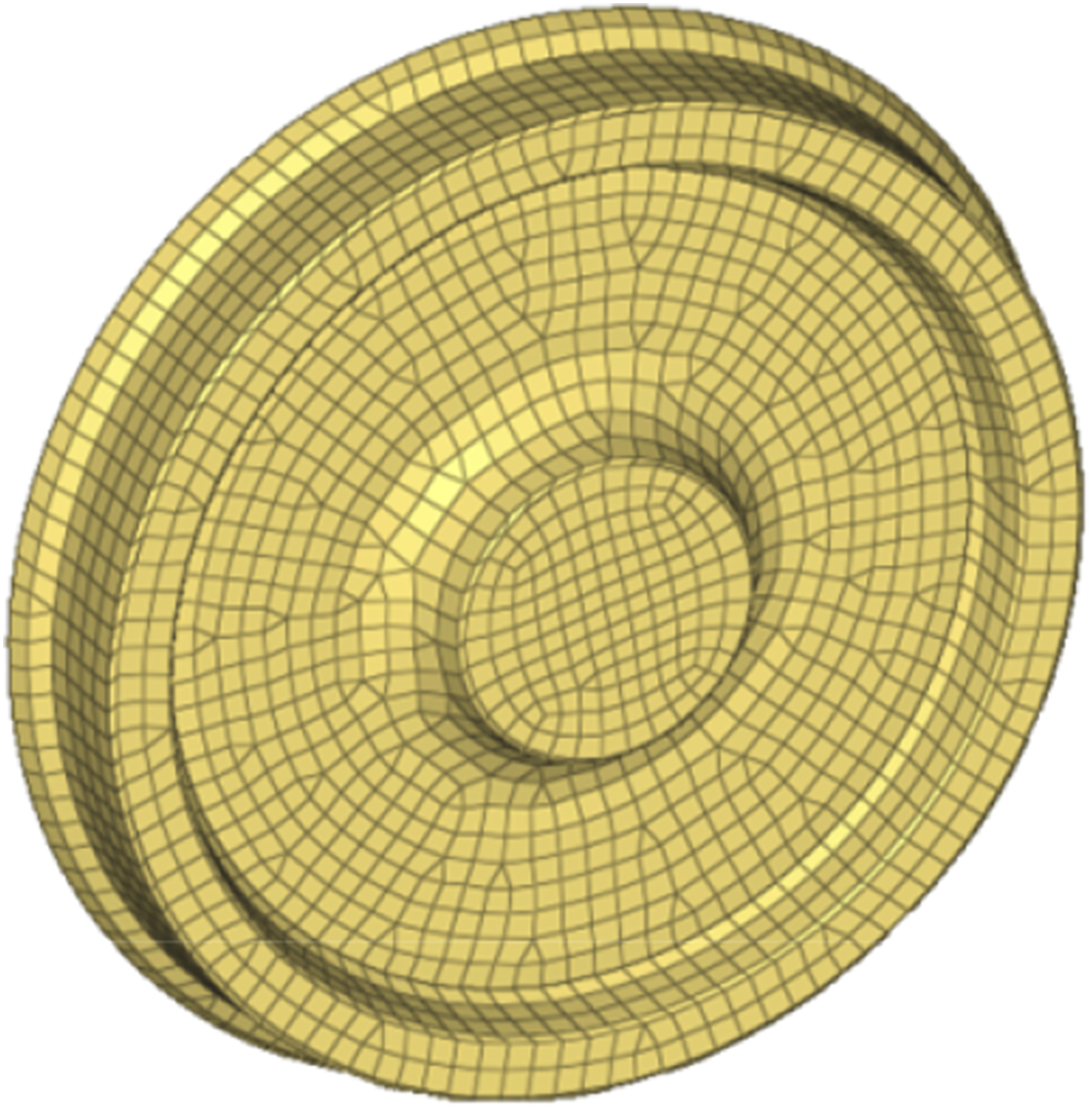
Vibration and sound radiation model of track based on FEM-BEM
Three-dimensional solid finite element models of the track structure are established to obtain vibration input, considering both conventional fasteners and particle-damped fasteners. The total length of the modeled track is 30 spans, corresponding to 18 m. The rails and particle dampers are modeled using solid elements, while the fasteners are represented by spring–damper elements. The mass and damping ratio of the particle dampers are based on the previously calculated equivalent mass and damping ratio. A vertical load is applied at the center of the rail. The bottom of the fastener springs is fully constrained, and symmetric boundary conditions are applied at the longitudinal ends of the track. Subsequently, a boundary element model of the track is constructed to analyze the acoustic radiation. The boundary element mesh is consistent with the surface mesh of the finite element model and is therefore not described separately. The finite element and boundary element meshes are shown in Figure 21. The finite element and boundary element meshes of rails: (a) With conventional fastener and (b) with particle-damped fastener.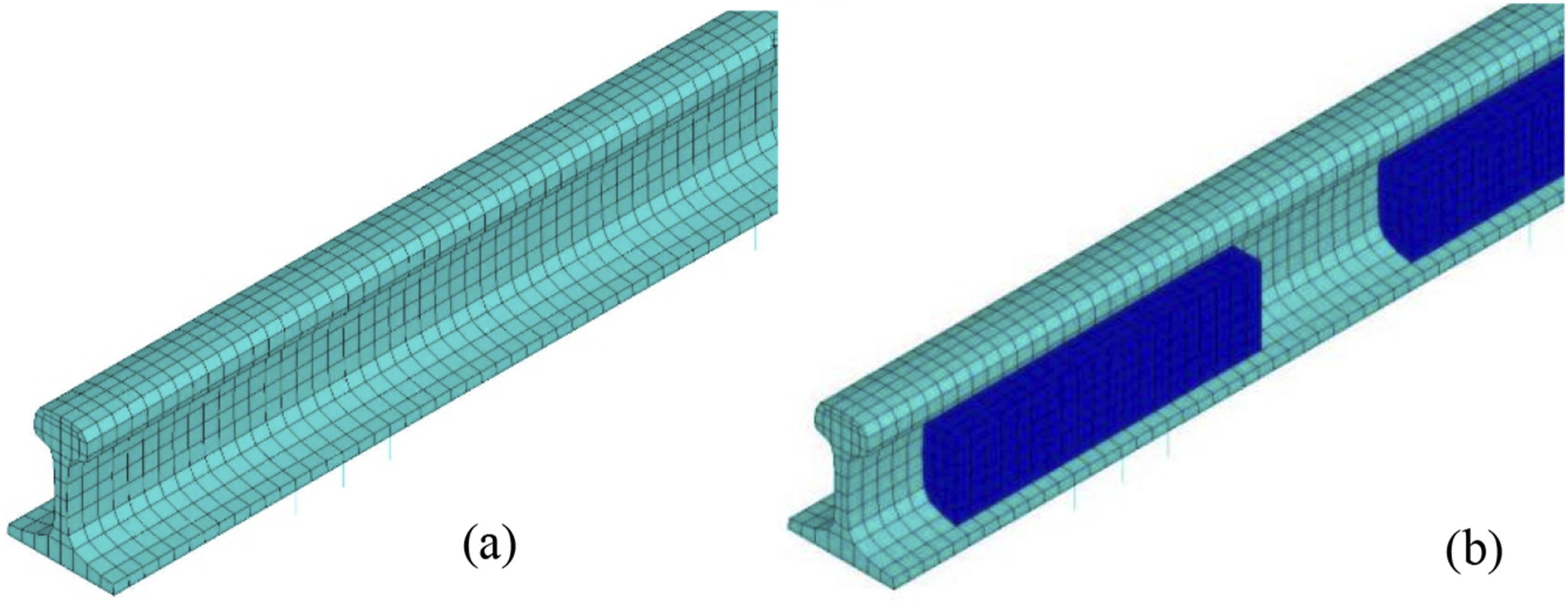
The interaction between the wheel and rail is consistent with that described in Section 3 and is therefore not repeated here.
Field test of wheel-rail noise and model validation
To verify the effectiveness of the wheel-rail noise model, wheel-rail noise tests were conducted on a metro line at speeds of 50 km/h, 60 km/h, and 70 km/h. The microphone was positioned 30 mm away from the wheel. A photo of the test site is shown in Figure 22. The test site photo of wheel-rail noise.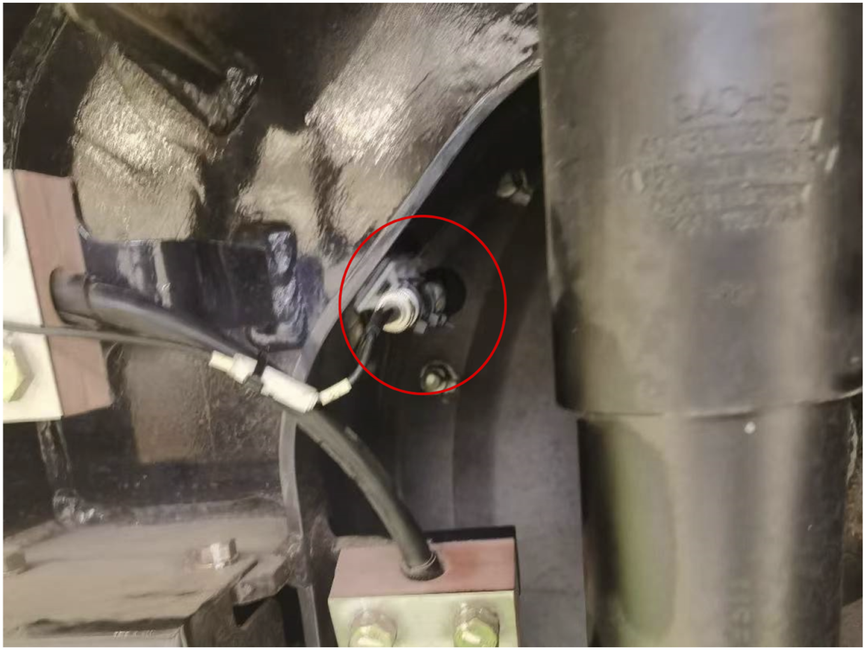
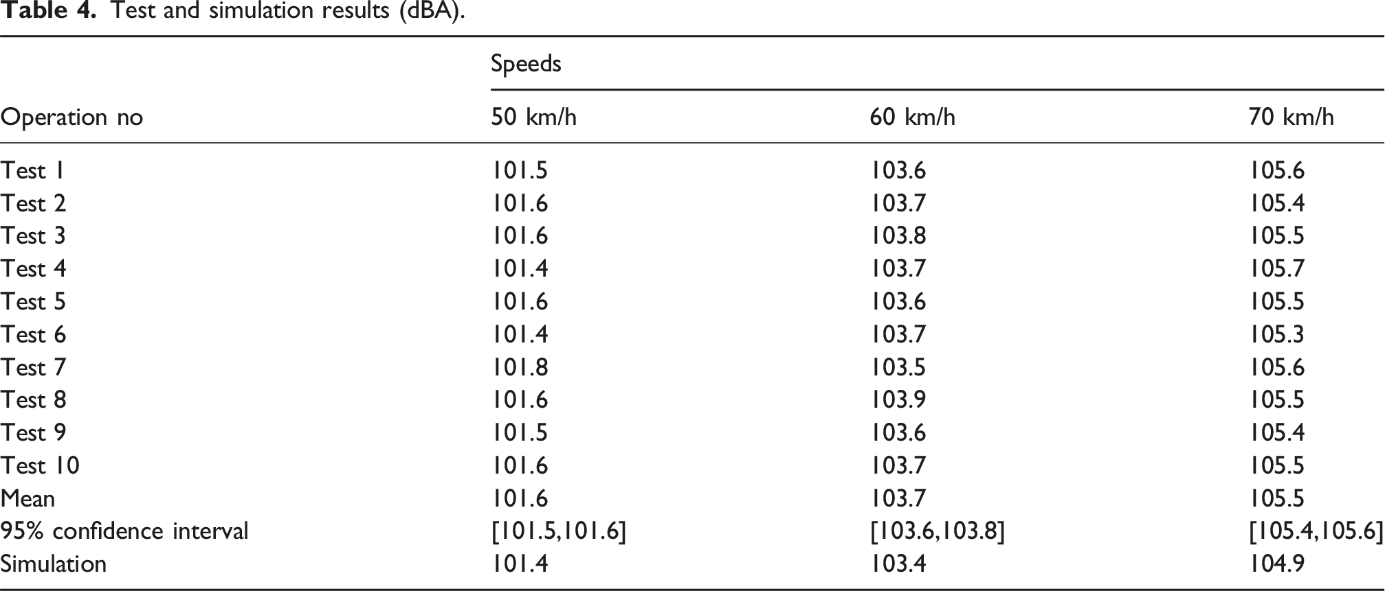
Test and simulation results (dBA).
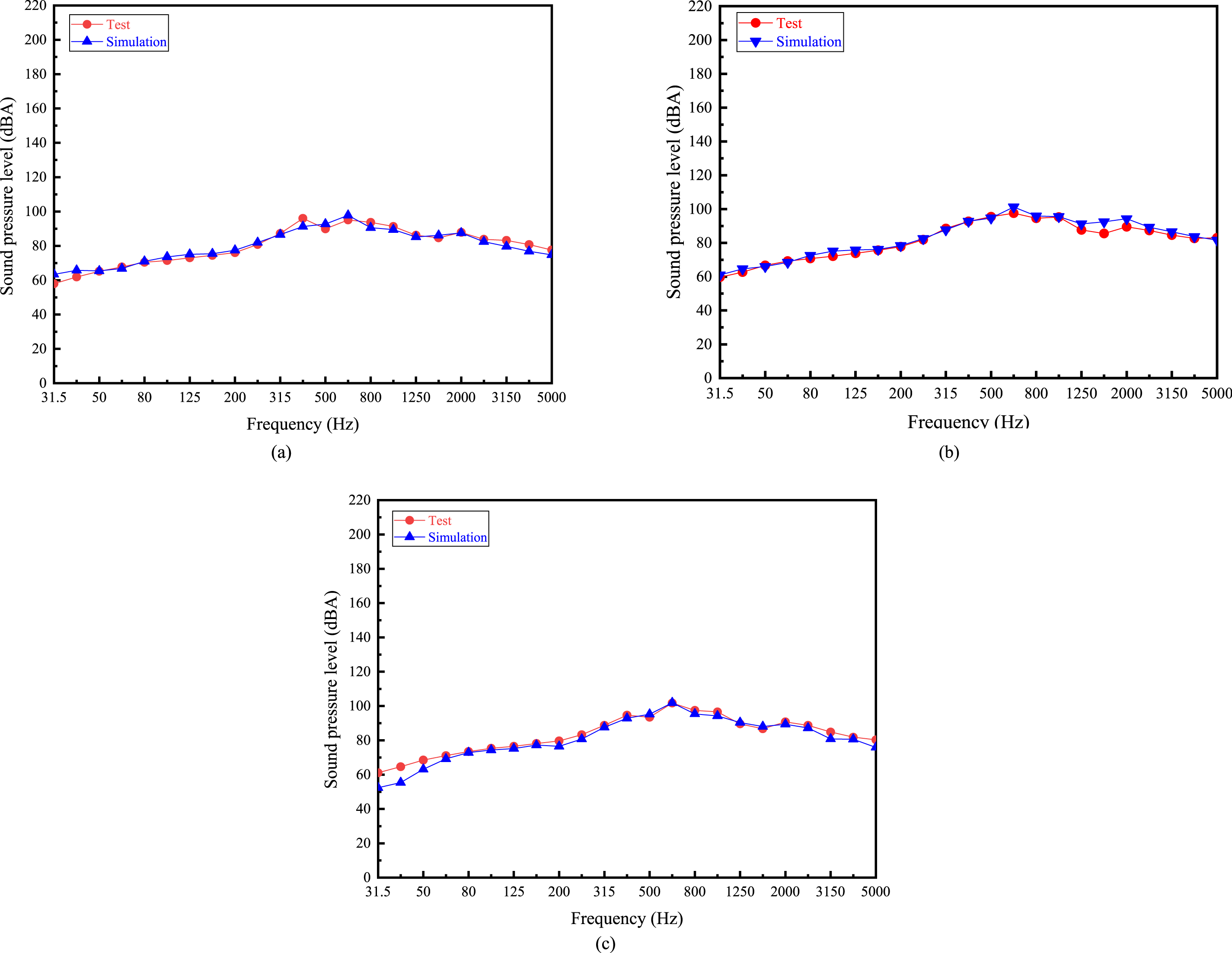
Spectral comparison between test and simulation: (a) 50 km/h; (b) 60 km/h; and (c) 70 km/h.
As shown in Table 4 and Figure 23, the simulation results agree well with the test results under the same conditions. The deviation between the simulation and the statistical test results is 0.1–0.7 dB(A), which falls within a relatively small and acceptable range for noise calculations.
Noise characteristics and noise reduction effect
Figure 24 shows the wheel-rail noise for conventional fastener and particle-damped fasteners with different pad stiffnesses, where the stiffness of the pad in the conventional fastener is 40 kN/mm. Wheel-rail noise for conventional fasteners and particle-damped fasteners with different pad stiffnesses.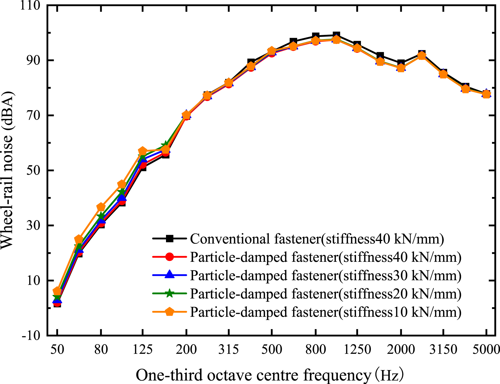
As can be seen from Figure 24, the noise value in the low-frequency band increases with the decrease of the stiffness of the elastic pad, while the change in the noise value in the high-frequency band is small. To facilitate the evaluation of the noise reduction effect of particle damping on wheel-rail noise, the total value of wheel-rail noise under these working conditions is shown in Figure 25. Total value of wheel-rail noise.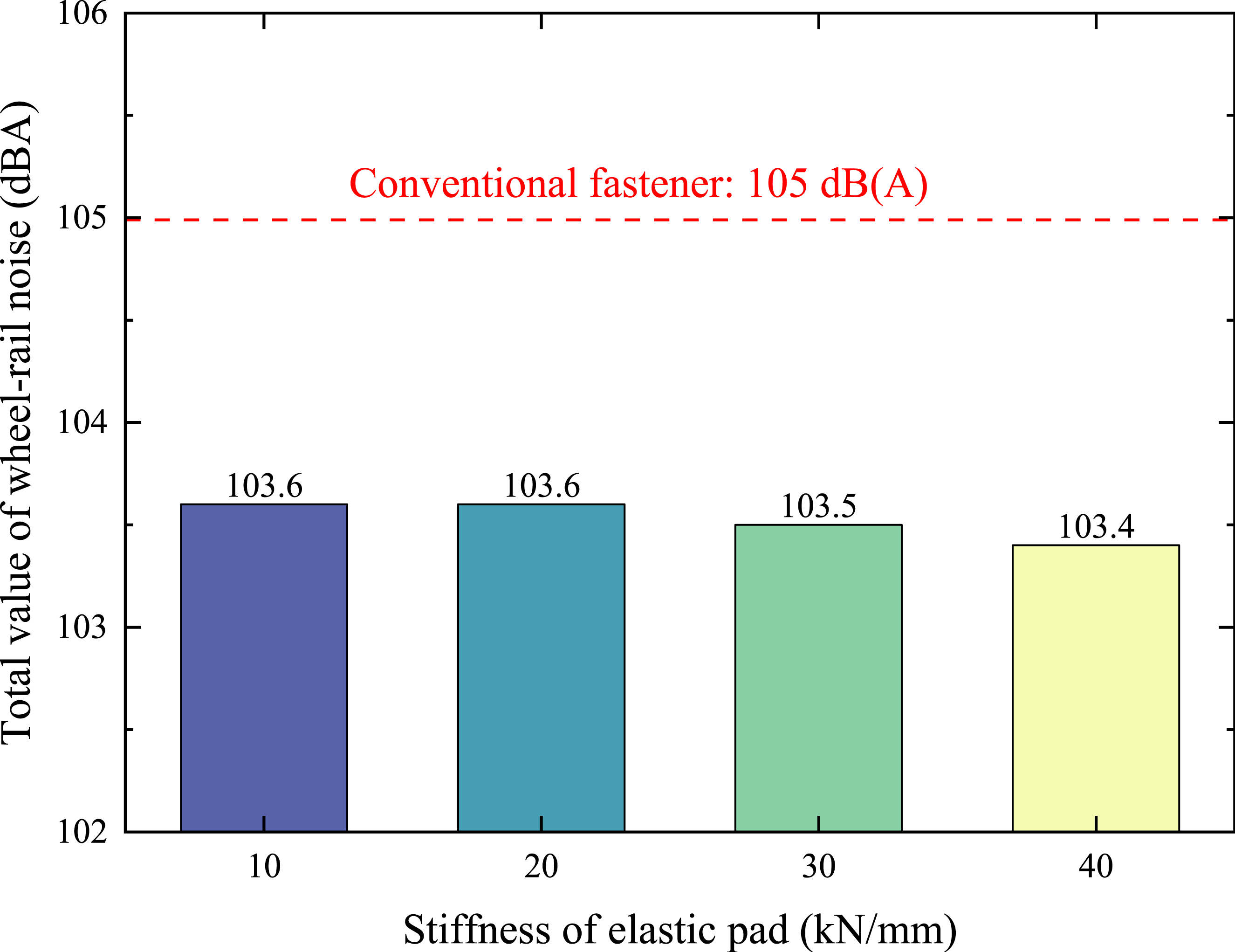
As shown in Figure 25, when the stiffness of the elastic pad ranges from 10 to 40 kN/mm, the total wheel-rail noise slightly increases as the stiffness of the particle-damped fastener decreases, though the increase is minimal. For instance, when the pad stiffness is 20 kN/mm, the noise reduction is only 0.2 dB higher than that with a stiffness of 40 kN/mm. This is because, even without considering the damping effect of the new fastener, a decrease in fastener stiffness tends to increase wheel-rail noise. 24 In summary, the particle-damped fastener with a pad stiffness of 40 kN/mm achieves the greatest noise reduction of 1.6 dBA. However, the fastener with a stiffness of 10 kN/mm still achieves a reduction of 1.40 dBA, with a negligible difference between the two. Considering the analysis of environmental vibration in Section 3, selecting a particle-damped fastener with a pad stiffness of 10 kN/mm offers the optimal balance between mitigating environmental vibration and reducing wheel-rail noise.
Based on the statistical analysis of the wheel-rail noise test results and the simulation validation in Section 4.2, it can be concluded that, taking simulation error into account, the simulated noise reduction of 1.6 dB(A) corresponds to an actual noise reduction range of 0.9 dB(A) (in the least favorable case) to 2.3 dB(A) (in the most favorable case) under real operating conditions. Although the noise reduction effect is relatively modest, it is an additional benefit achieved on top of the effective vibration reduction already demonstrated in Section 3. Typically, vibration-damping fasteners cannot reduce noise and may even amplify it. Therefore, the simulated 1.6 dB(A) noise reduction achieved by the fastener system in this study—when combined with the environmental vibration mitigation—contributes positively to the overall goal of vibration and noise reduction. Moreover, this combined effect is practically perceptible and meaningful.
Conclusions
(1) A discrete element–dynamic coupling model was established and combined with experimental studies to investigate the influence of particle-damped fastener parameters on its damping performance. The particle filling ratio has a significant impact on the damping ratio of the fastener. When the filling ratio increases from 0% to 90%, the damping ratio of the particle damper increases accordingly. However, when the filling ratio approaches 100%, the damping ratio decreases instead. (2) A 2.5D finite element–boundary element coupled model incorporating particle-damped fasteners was developed to predict environmental vibration. The effectiveness of particle-damped fasteners in reducing environmental vibration was investigated. Compared with the conventional fastener, the particle-damped fastener with the same stiffness reduces vibration by 2.4 dB, while the one with a stiffness of 10 kN/mm achieves a reduction of 5.6 dB. (3) A 3D finite element–boundary element coupled model incorporating particle-damped fasteners was developed to predict wheel-rail noise, and the noise reduction performance of the particle-damped fastener was analyzed. Under the same fastener stiffness, the particle-damped fastener can reduce wheel-rail noise by 1.6 dB(A). Considering its combined effect on both environmental vibration and noise reduction, a particle-damped fastener with a stiffness of 10 kN/mm offers better overall vibration and noise mitigation performance.
Footnotes
Funding
The author(s) disclosed receipt of the following financial support for the research, authorship, and/or publication of this article: the present work is supported by the National Natural Science Foundation of China (52002340), and the Fundamental Research Funds for the Central Universities (2682024CG007).
Declaration of conflicting interests
The author(s) declared no potential conflicts of interest with respect to the research, authorship, and/or publication of this article.