
Abstract
Review of technical literature regarding to train-induced vibrations shows that the effects of unsupported railway sleepers on this issue have been less investigated. So, the present study was devoted to numerical investigations of the mentioned issue. In this regard, first the problem of longitudinal train–track dynamic interaction was simulated in two dimensions by using the finite element method and the developed model was validated through comparison of the results with those obtained by previous researchers. In the next stage, a series of sensitivity analyses were accomplished to account for the effects of value of gap beneath the unsupported sleeper(s) and the track support stiffness on increasing the sleeper displacement and track support force. Moreover, the raised sleeper support force was introduced as applied load to a two-dimensional plane strain finite element model of track in lateral section and consequently the train-induced vibrations were assessed. As a result, a series of regression equations were established between the peak particle velocity in the surrounding environment of railway track and the sleeper support stiffness for tracks without unsupported sleepers and with one and two unsupported sleepers.
Keywords
Introduction
Among the various parameters affecting the ballasted track mechanical behaviour, track support conditions and track stiffness have major importance. One of the key problems which commonly occurs in the ballasted railway tracks is unsupporting of the sleepers due to local settlements in ballast layer. By passing the moving trains, the track components such as rail, sleepers and the fasteners are faced to early damage and deterioration when unsupported sleepers exist in the ballasted tracks system. When a sleeper hangs up from the rail, its share of vertical load in conjunction with rail is transferred to adjacent sleepers so they will undergo more deformations, forces and stresses. Some researchers have worked in the field of dynamic train–track interaction for various railway track conditions. In this regard, Sun et al. 1 examined dynamic responses of rail track and wagon by coupling two subsystems with Hertz contact theory. Nielsen and Abrahamsson 2 analysed the track including beam elements under the effect of moving vehicle with four degrees of freedom. Kerr 3 analysed and designed the railway tracks under moving vehicles considering different track parameters including rail support modulus, track stiffness, axial stress, rail buckling, etc. Zhai et al. 4 investigated railway ballast vibrations including pyramid model by using theoretical simulations and field experiments. Suzuki et al. 5 measured the dynamic behaviour of railway track near to rail joints under the moving vehicle effect. Lundqvist and Dahlberg 6 studied the effects of voided sleeper on track dynamic behaviour under a moving train wheel-set by considering computer model. Zakeri et al.7–9 investigated the effects of unsupported sleeper, track parameters and rail irregularity by considering the train–track dynamic interaction model. Lei and Zhang 10 studied the effects of track stiffness in transitions by considering train–track dynamic interaction. Koroma et al. 11 investigated the effects of rail pads on railway track vibrations under passing harmonic loads by utilizing the finite element model. Also in the presence of unsupported sleepers in tracks, the train-induced vibrations in surrounding environment increase and consequently produce some annoyances in surrounding structures in residential areas. Some researchers have worked in the field of ground-borne vibrations due to moving trains. For example, Cai et al. 12 investigated the influence of vehicle–track interaction with rail irregularities on ground surface vibrations by solving the equations of motions analytically. Adam and Von Estorff 13 studied the effect of trenches on reducing the building vibrations due to passing train by utilizing a two-dimensional numerical model. Ni et al. 14 and Yang and Hung 15 studied the train-induced vibrations by developing a finite element model. Zakeri et al. 16 investigated numerically the effects of step-shaped trench in order to reduce the train-induced vibrations on the surrounding building. Esmaeili et al. 17 experimentally and numerically studied the effects of ballast layer solidification on ground-borne vibrations due to passing train. Nielsen et al. 18 presented a hybrid model for evaluating the ground-borne vibrations generated by rail and wheel irregularities. Kouroussis et al.19,20 investigated the effects of wheel and rail singular defects and irregularities on ground-borne vibrations by considering the numerical modelling. Younesian and Sadri 21 investigated the effects of multitrenches for reducing the train-induced vibration by using the finite element method (FEM). Trollé et al. 22 reviewed the effects of vibration and annoyance on building residents due to ground transportation vehicles by focusing on railway traffic.
None of the mentioned researchers have taken into account the ground-borne vibrations due to unsupported sleeper’s existence in the ballasted railway tracks. Consequently, the present study was allocated to numerical investigations of the effects of unsupported sleepers in increasing the ground-borne vibrations due to railway vehicle passage. In this regard, two finite element codes were used for vehicle–track interaction analysis and evaluation of train-induced wave propagation in surrounding media. In this matter, from the first code, the maximum track support force was obtained and it was introduced to the second code as input. Consequently by evaluating the effect of unsupported sleepers on increasing the sleeper support force in longitudinal direction of railway track, its effect on increasing of the peak particle velocity (PPV) of surrounding environment was numerically investigated by the second FEM code. Finally, many regression equations were derived between the parameters of track with unsupported sleeper with those are dominant in environmental vibrations.
Railway vehicle – track interaction simulation
For analysis of railway tracks behaviour under the moving vehicle, different track models can be considered. In order to calculate the displacement and support force of sleepers, a railway track including rail and sleepers is simulated by using the FEM. In this regard, using the developed models by Zakeri and Xia
8
and Zakeri et al.,
9
the mass, damping and stiffness matrix of rail and then sleepers are derived and assembled. During the modelling, each rail joint has two degrees of freedom including vertical displacement and rotation. Moreover, each sleeper has one degree of freedom including vertical displacement. Figure 1 illustrates the railway track model including rail and sleepers which have been connected with springs and dampers.
Railway track model including two unsupported sleepers.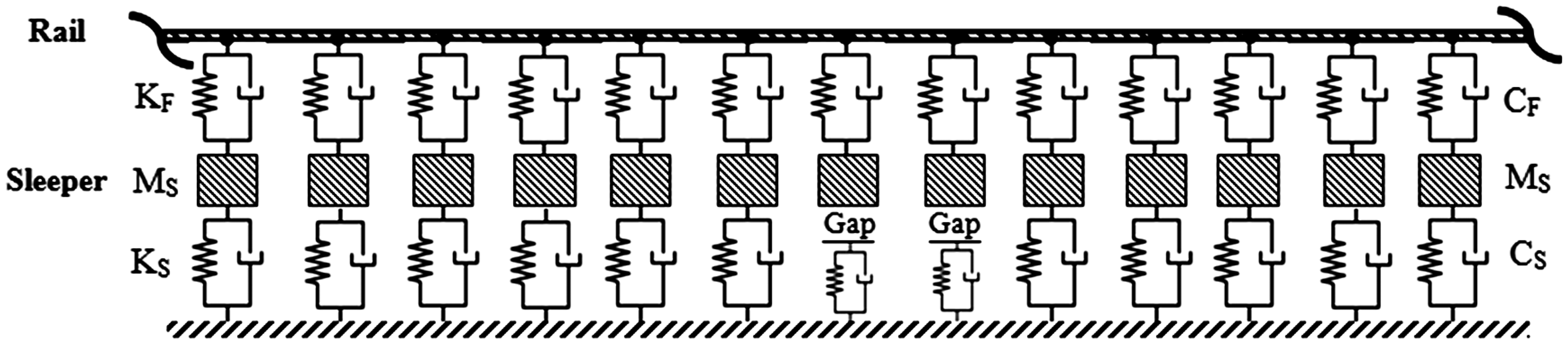
In Figure 1, KF and CF are the stiffness and damping of track fastening system, respectively. Also, KS and CS are the stiffness and damping of track support, respectively. In addition, MS presents sleeper mass. The stiffness [KRail], mass [MRail] and damping [CRail] matrix of each rail element are determined as follows
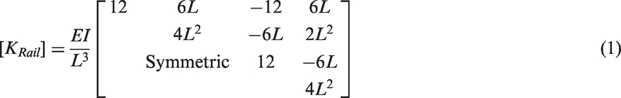
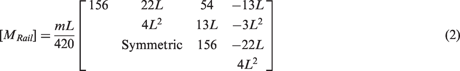

In these matrices, E, I, m and L are Young’s modulus, moment of inertia, mass per unit length and element length, respectively. Also, αR and βR are Rayleigh damping coefficients. After calculating the matrix of each rail element, the total matrix of rail is determined by assembling all rail elements. Then, the same matrix of each sleeper is derived based on its motion equation as follows

In this equation, YR and YS are the vertical displacement of rail and sleeper, respectively. Also,
For railway track loading, the railway vehicle with four axle loads is passed over the track. For simulation of vehicle, first the motion equations of vehicle components are derived and then the mass, damping and stiffness matrix of railway vehicle are determined. In this regard, the carbody and each bogie have two degrees of freedom including vertical displacement and rotation and also, each wheel has one degree of freedom including vertical displacement. In general, railway vehicle has 10 degrees of freedom. Figure 2 shows the configuration of the railway vehicle model.
Railway vehicle model.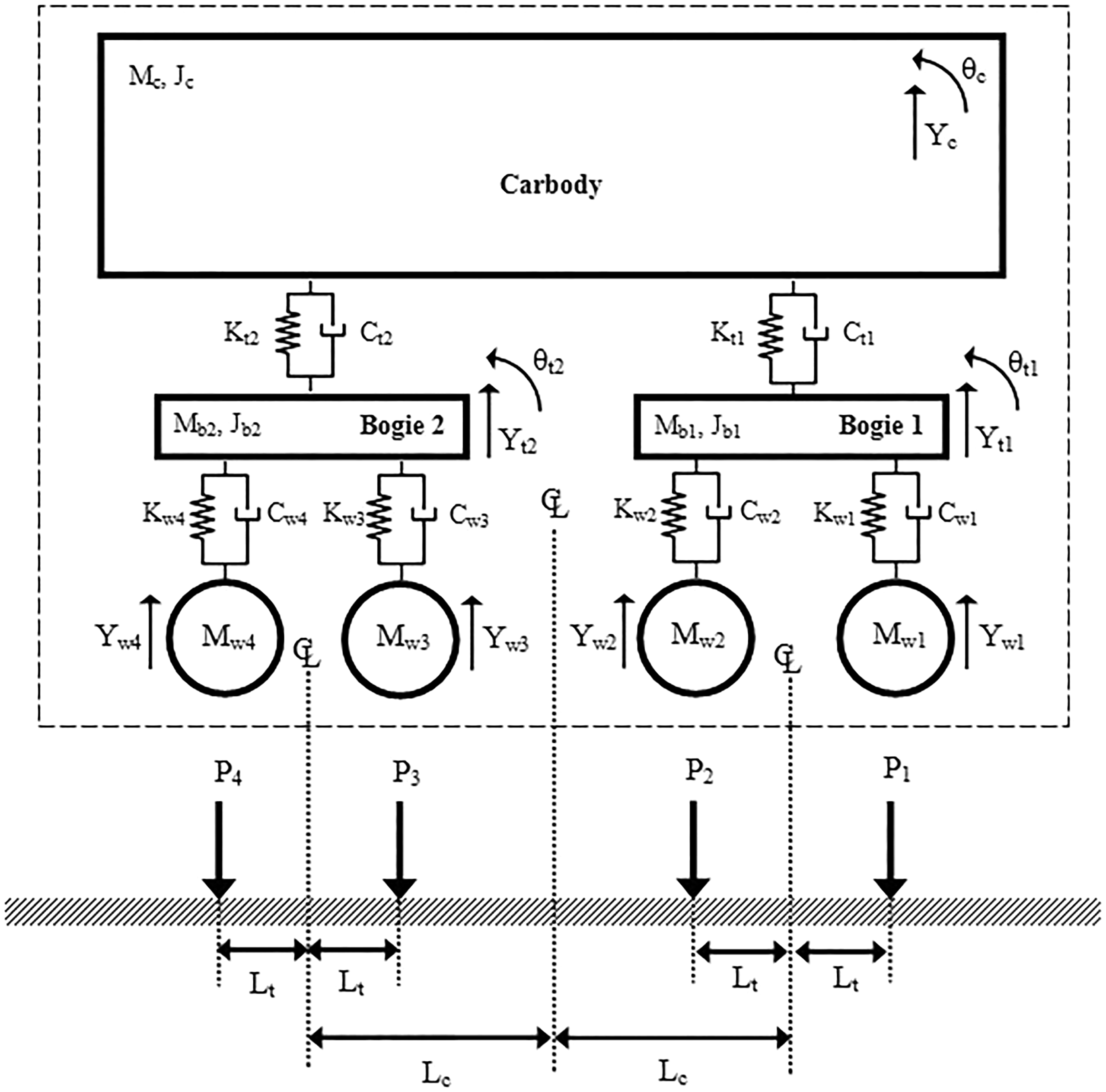
In Figure 2, the vehicle model includes carbody, two bogies and four wheels. The mass and rotational inertia of carbody are Mc and Jc, respectively. Also, Mt1 and Jt1 are the mass and rotational inertia of bogie 1 while Mt2 and Jt2 belong to bogie 2. In this figure, Lt and Lc are the half distance of two wheels and two bogies, respectively. Kt1, Ct1 and Kt2, Ct2 are the stiffness and damping of bogies 1 and 2, respectively. Also, Kw1, Kw2, Kw3 and Kw4 are the stiffness of wheels 1, 2, 3 and 4, respectively. Moreover, Cw1, Cw2, Cw3 and Cw4 are the damping of wheels 1, 2, 3 and 4, respectively. The motion equations of car body, bogies and wheels are presented as follows:
Vertical motion equation of car body (Yc)
Rotational motion equation of car body (θc)
Vertical motion equation of bogie 1 (Yt1)
Rotational motion equation of bogie 1 (θt1)
Vertical motion equation of bogie 2 (Yt2)
Rotational motion equation of bogie 2 (θt2)
Vertical motion equation of wheel 1 (Yw1)
Vertical motion equation of wheel 2 (Yw2)
Vertical motion equation of wheel 3 (Yw3)
Vertical motion equation of wheel 4 (Yw4)


Numerical results of vehicle–track interaction model
In this section, first the vehicle–tracks interaction model is validated and in continuation, a series of sensitivity analyses are performed.
Vehicle–track interaction model validation
For validation of presented model, the analysis results are compared with those presented by Lei and Zhang.
10
Figure 3 illustrates the rail deflection under the moving vehicle effect.
Rail vertical displacement due to moving vehicle.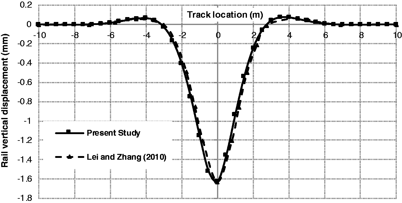
As can be seen from Figure 3, there is a good agreement between the results of present study model and the work of Lei and Zhang. 10 In continuation, a series of sensitivity analyses are performed on the railway track dynamic interaction considering the unsupported sleepers parameters.
Sensitivity analyses results
In the previous part, the modelling procedure of train–track system by using the FEM was explained and the developed model was validated with reported results of Lei and Zhang.
10
In this section, numerical results of train–track system are presented for the various cases including railway track without unsupported sleepers, track with an unsupported sleeper and track with two unsupported sleepers. During dynamic analyses, a spring and damper are imposed beneath the sleeper. For modelling the unsupported (or partially supported) sleeper condition, a gap can be imposed beneath the sleeper. Consequently, the spring stiffness and damping of sleeper support can be conditionally defined as follows
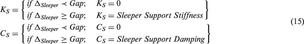
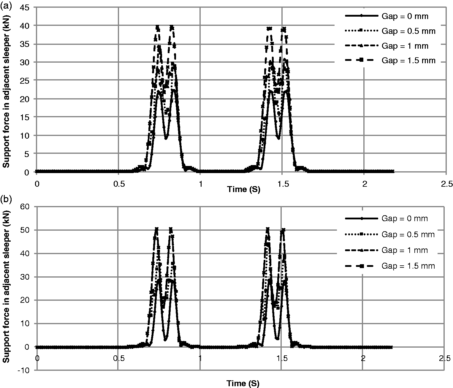
Figures 4 and 5 show the displacements of sleeper and track sleeper support forces in adjacent sleeper, respectively, due to the analysis of railway track with an unsupported sleeper for different track support stiffness and gaps values beneath the unsupported sleeper.
Displacement of sleeper with an unsupported sleeper. (a) Minimum support stiffness 50 MN/m and (b) maximum support stiffness 200 MN/m. Track support force in adjacent sleeper with an unsupported sleeper. (a) Minimum support stiffness 50 MN/m and (b) maximum support stiffness 200 MN/m.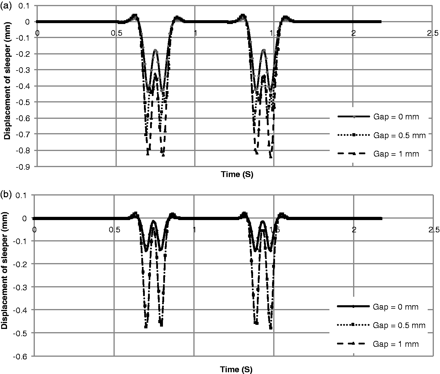
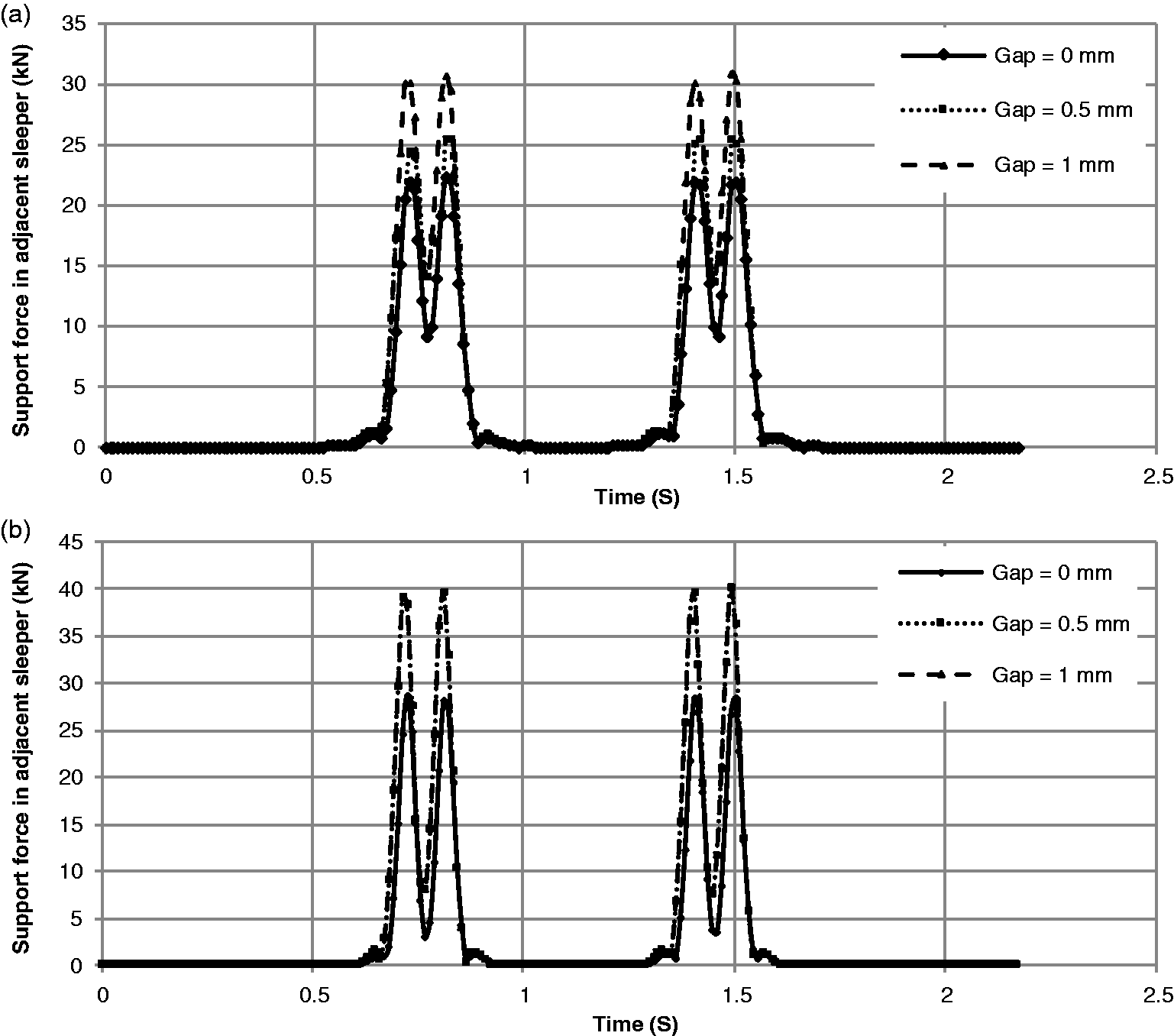
As can be observed from Figures 4 and 5, the absolute displacement of sleeper increases when there is an unsupported sleeper in the railway track. Also, it decreases by increasing the track support stiffness. For example, the absolute displacement of track with an unsupported sleeper increases 93.2% with respect to the track without unsupported sleepers while the track stiffness is 50 MN/m. On the other hand, by increasing the support stiffness from 50 to 200 MN/m, the absolute displacement of sleeper decreases 43.3% with respect to the gap value of 1.5 mm. Moreover, the support force of adjacent sleeper increases when an unsupported sleeper exists in the track. For instance, the ratio of support force of track with an unsupported sleeper to track without unsupported sleepers is 1.39. Figure 6 depicts the maximum displacement of sleeper and support force in track with an unsupported sleeper for various support stiffness and gap values.
Maximum displacement of sleeper and support force in track with an unsupported sleeper. (a) Maximum displacement of sleeper and (b) maximum track support force in adjacent sleeper.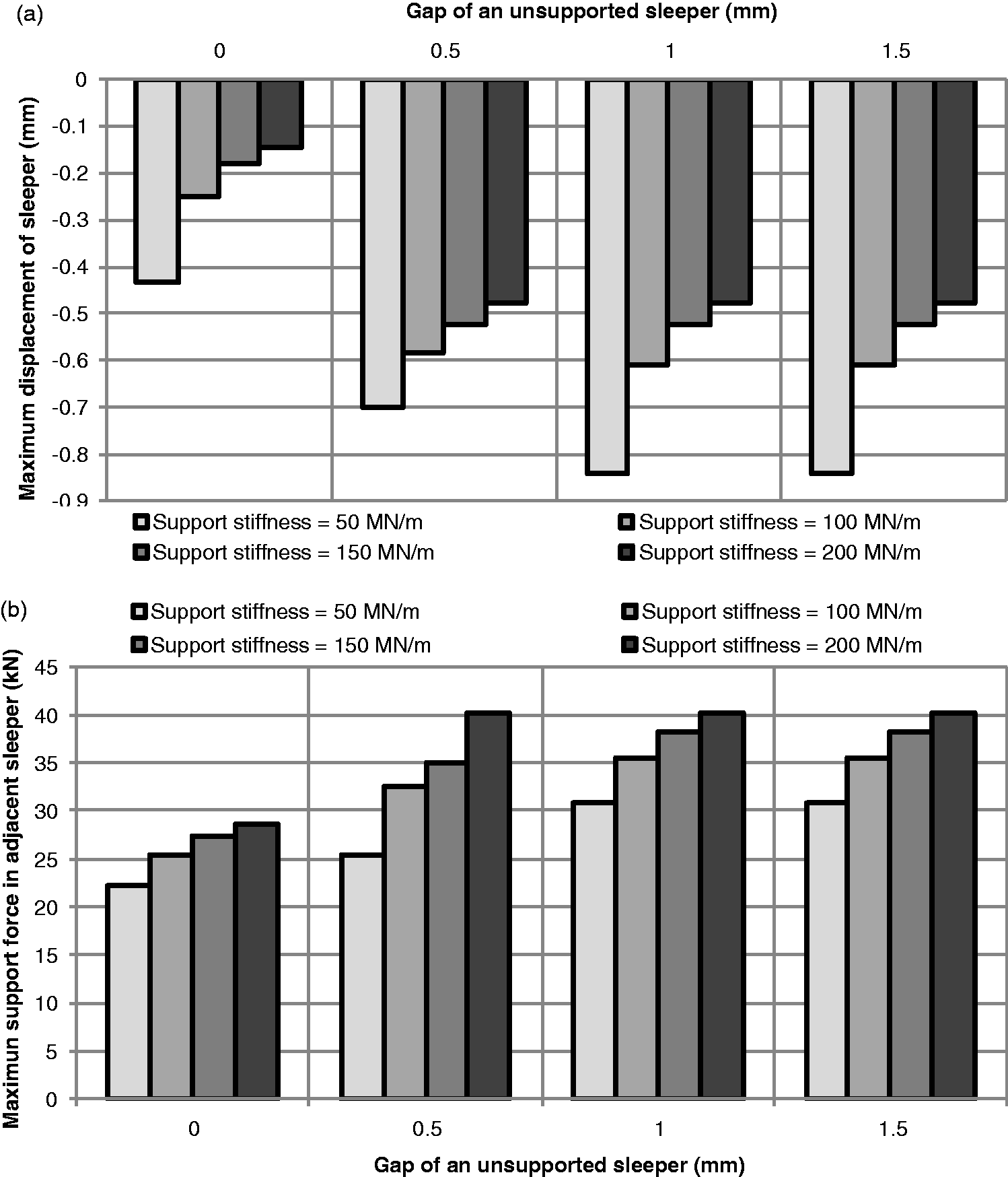
Based on Figure 6, the absolute maximum sleeper displacement and support force in adjacent sleeper increase when there is an unsupported sleeper in the track with respect to track without unsupported sleepers. In continuation, the effects of two unsupported sleepers are investigated. Figures 7 and 8 indicate the displacements of sleeper and track sleeper support forces in adjacent sleeper, respectively, due to the analysis of railway track with two unsupported sleepers for different track support stiffness and gap values beneath unsupported sleepers.
Displacement of sleeper with two unsupported sleepers. (a) Minimum support stiffness 50 MN/m and (b) maximum support stiffness 200 MN/m. Track support force in adjacent sleeper with two unsupported sleepers. (a) Minimum support stiffness 50 MN/m and (b) maximum support stiffness 200 MN/m.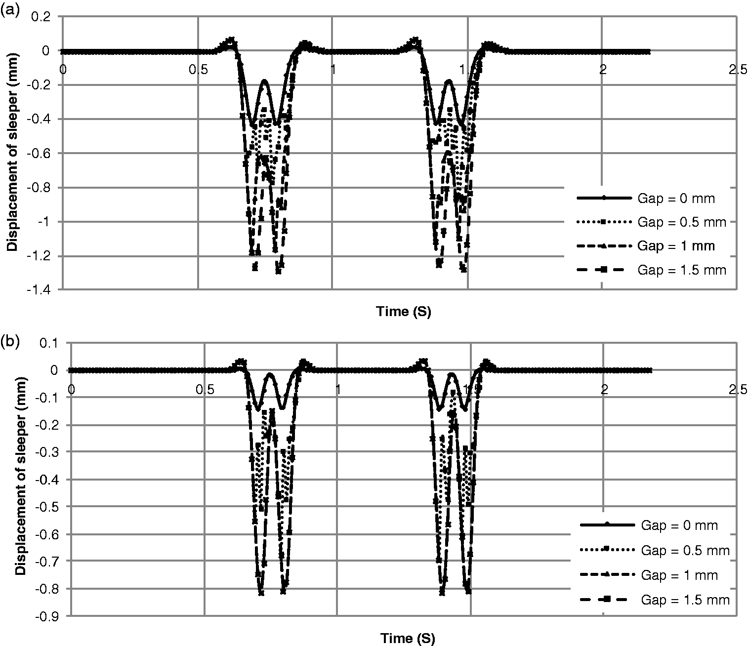
As can be seen from Figures 7 and 8, the sleeper displacement increases when there are two unsupported sleepers in the railway track compared to track with an unsupported sleeper while it decreases by increasing the sleeper support stiffness. For example, the absolute displacement of sleeper with two unsupported sleepers increases 53.88% with respect to the track with an unsupported sleeper in the case of track stiffness 50 MN/m. Also by increasing the support stiffness from 50 to 200 MN/m, the sleeper deflection decreases 36.8% for a gap of 2 mm. Furthermore, the support force of adjacent sleeper increases 1.28 times when two unsupported sleepers exist in the track with respect to the track with an unsupported sleeper. Figure 9 illustrates the maximum sleeper displacements and support forces in adjacent sleeper of track with two unsupported sleepers for various support stiffness and gap values.
Maximum displacement of sleeper and support force in track with two unsupported sleepers. (a) Maximum displacement of sleeper and (b) maximum track support force in adjacent sleeper.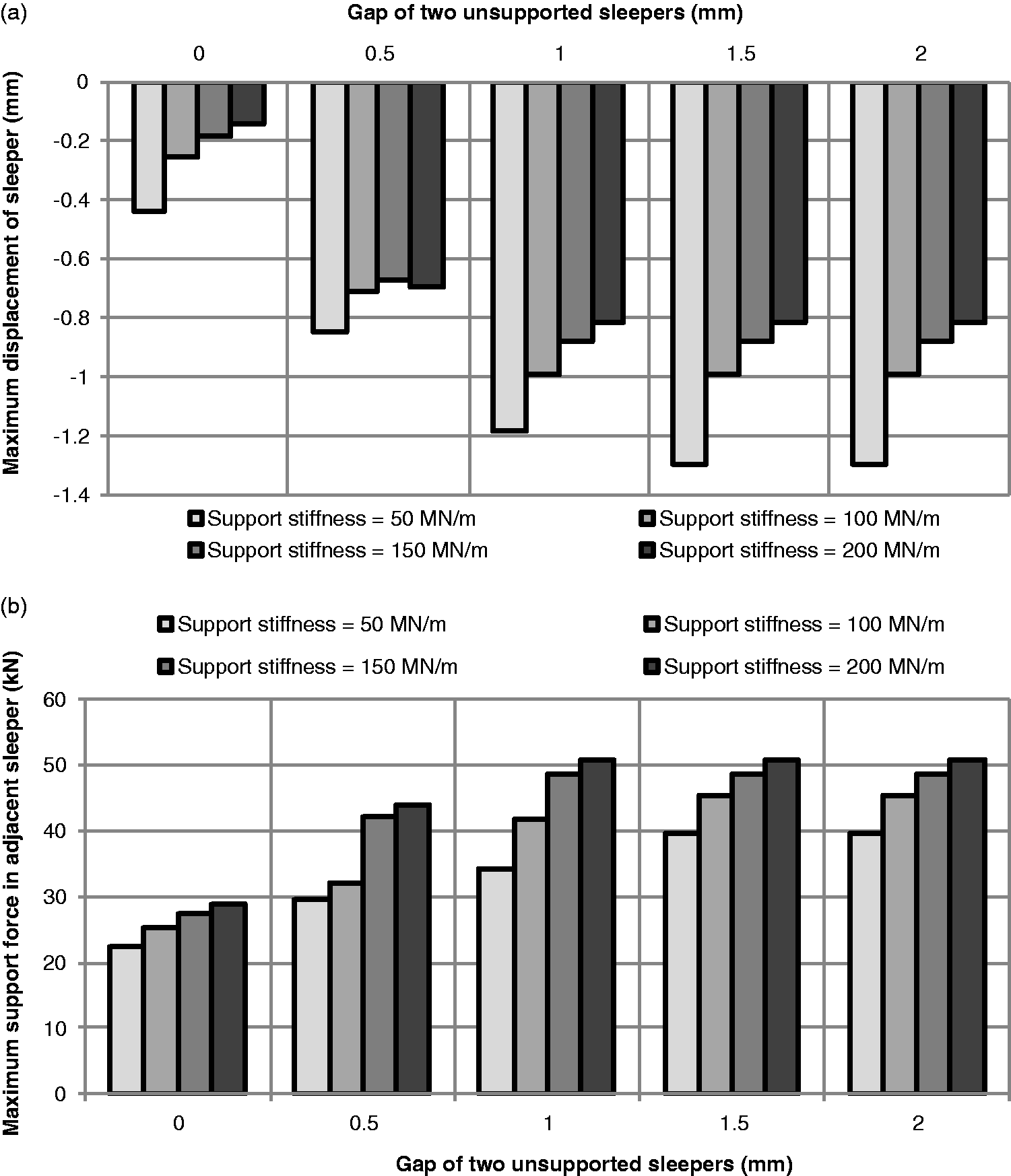
According to Figure 9, the maximum displacement of sleeper and support force in adjacent sleeper increase when there are two unsupported sleepers in the track with respect to the track with an unsupported sleeper and track without unsupported sleepers. Figure 10 shows the effects of vehicle speed on track support force under the various conditions of railway track for support stiffness 50 MN/m.
Maximum track support force in adjacent sleeper.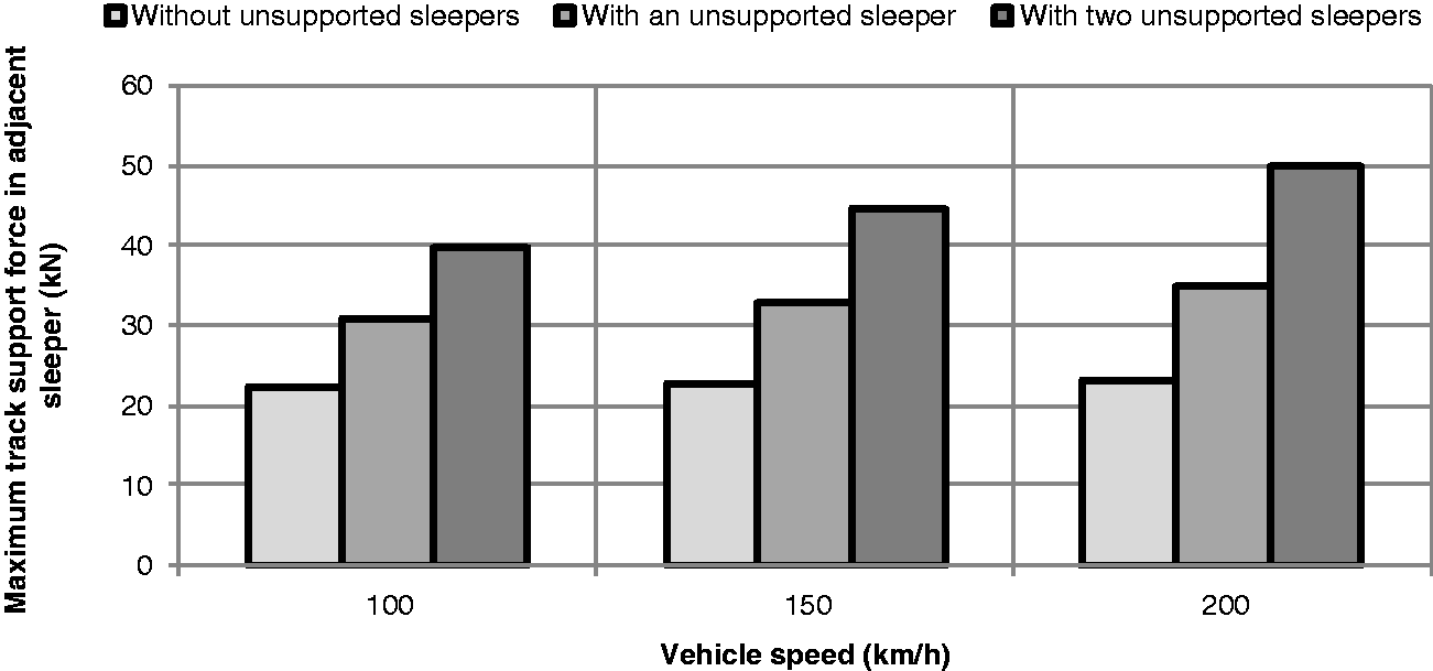
As can be observed from Figure 10, track support force increases 4.6, 13.2 and 25.6% due to increase in vehicle speed from 100 to 200 km/h for track without unsupported sleepers, track with one and two unsupported sleepers, respectively. In continuation, the environmental vibrations are investigated for various conditions of railway track including unsupported sleeper(s).
Numerical model for assessing the train-induced vibration model
In this section, the numerical model for evaluation of ground-borne vibrations is presented. This model which is developed by plane strain elements of ABAQUS as well-known finite element code has two parts including the near and far fields. The near field contains railway and surrounding media and the far field includes infinite space. The near field is modelled by using plane strain finite elements and the far field is simulated by using the dashpot elements as absorbing boundaries.
23
According to theory of elasticity, the elastic settlement of subgrade (Se) under a rectangular foundation is calculated based on the following equation

In this equation, ES, μS, q and B are subgrade elastic modulus, subgrade Poisson’s ratio, mean stress value beneath the foundation and foundation width, respectively. Also, I1, I2 and IF are correction factors.
24
So, the subgrade elastic modulus can be using the following equation

In this equation, KS and A are the subgrade stiffness and base area of sleeper, respectively. In this model, the load is applied to track centreline and consequently the environmental vibrations are calculated in the ground surface for various bench points.15–17 Figure 11 shows the model of environmental vibrations.
Environmental vibration model.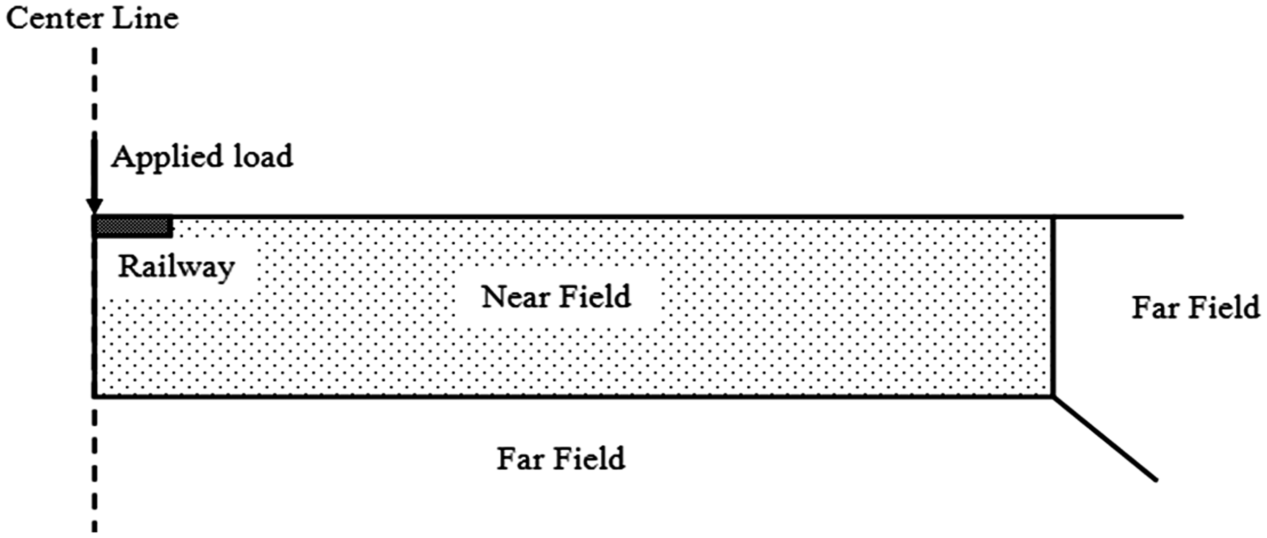
Validation of ground-borne vibration numerical model
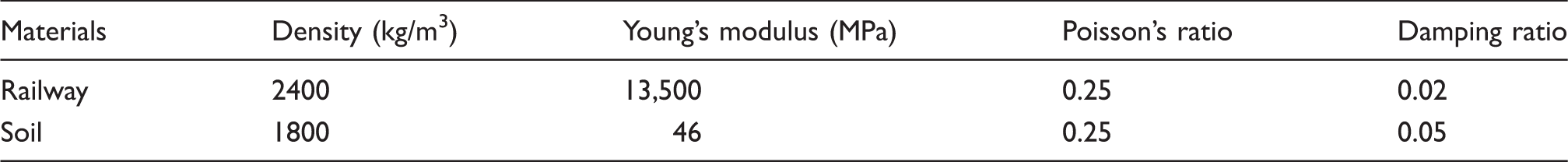
Specifications of vibration model parts. 15
The index of train environmental vibrations, i.e. amplitude reduction ratio (Ar) is calculated as follows

Figure 12 illustrates the obtained amplitude reduction ratio (Ar) in the present study and other researchers’ studies.
Validation of the results in present study.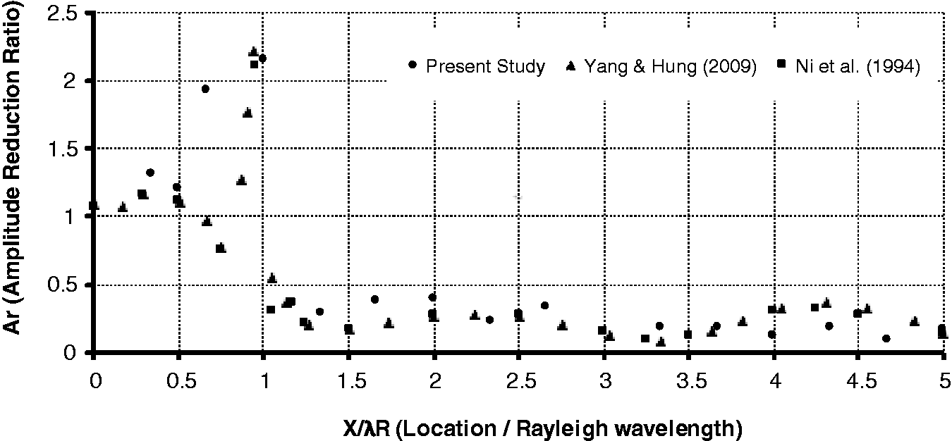
As shown in Figure 12, the presented results have a good agreement with the mentioned works. Consequently, it can be claimed that the finite element model of wave propagation has enough validity. In continuation, a series of sensitivity analyses are accomplished on the environmental vibration model for track without unsupported sleepers, track with an unsupported sleeper and track with two unsupported sleepers.
Effects of unsupported sleeper on ground-borne vibrations
In the previous section, the FEM modelling procedure for assessing the train-induced environmental vibrations and its validation were described. In this part, the environmental vibration results with respect to various track support conditions including track without unsupported sleepers, track with an unsupported sleeper and track with two unsupported sleepers are presented. In this regard, the maximum track support forces in adjacent sleeper which were calculated for different support conditions and stiffness in previous section are applied to the vibration model as input force. Consequently, the environmental vibrations are determined for various bench points. Figures 13 and 14 indicate the time histories of vibration velocities for different points in the environmental vibration model.
Vibration velocity for minimum support stiffness 50 MN/m at various distances from applied load. (a) Vibration velocity at distance of 3 m from applied load, (b) vibration velocity at distance of 6 m from applied load and (c) vibration velocity at distance of 10 m from applied load. Vibration velocity for maximum support stiffness 200 MN/m at various distances from applied load. (a) Vibration velocity at distance of 3 m from applied load, (b) vibration velocity at distance of 6 m from applied load and (c) vibration velocity at distance of 10 m from applied load.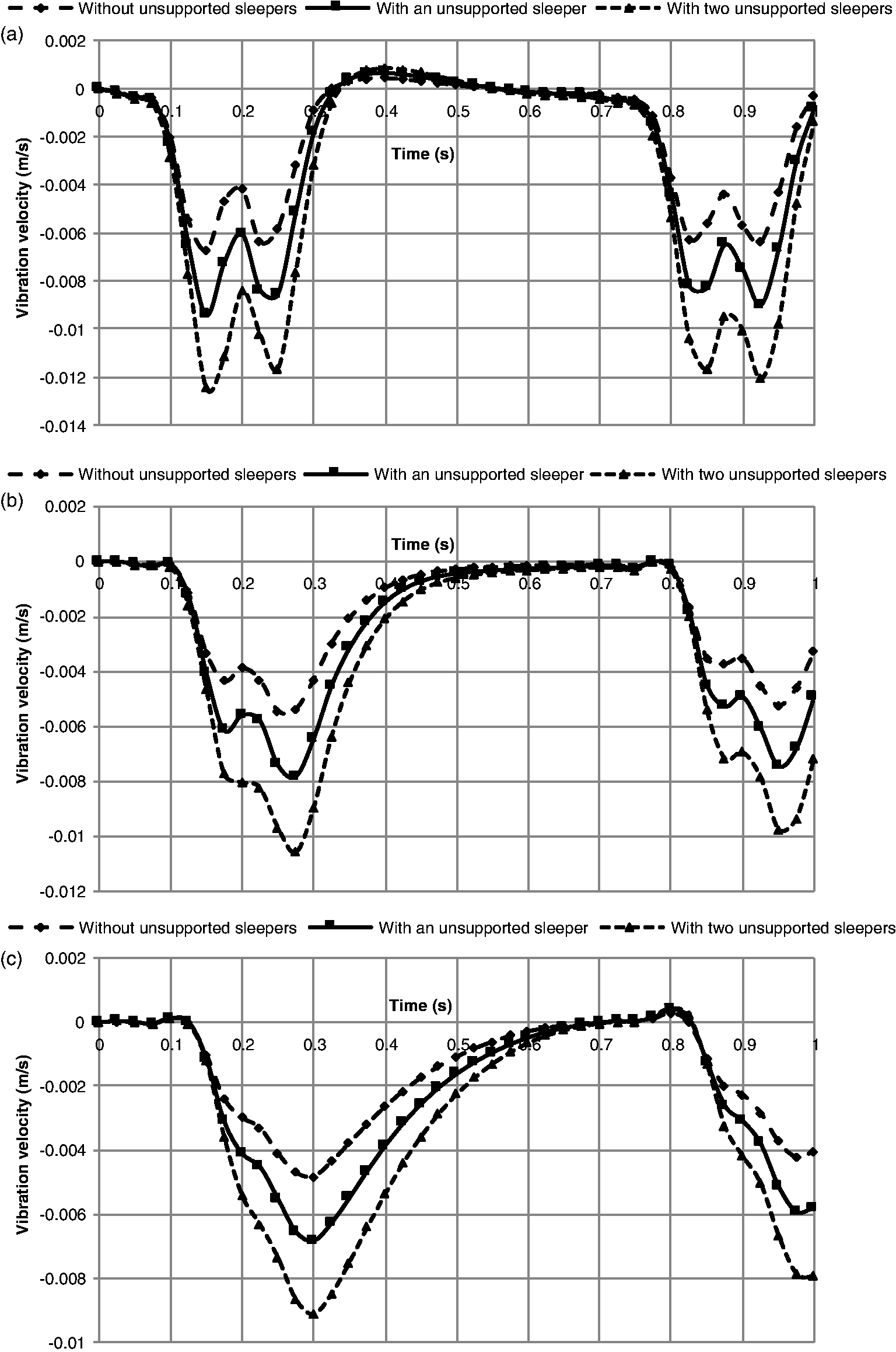
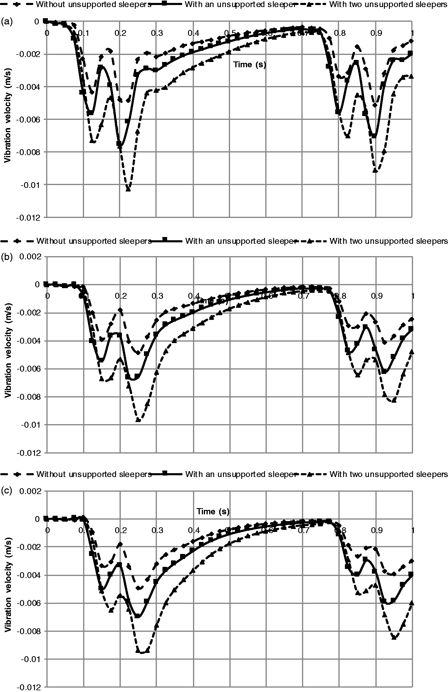
As can be observed from Figures 13 and 14, at a distance of 3 m from applied load, the maximum vibration velocity increases 39.9 and 47.4%, respectively, for track support stiffness 50 and 200 MN/m in the case of presence of an unsupported sleeper with respect to track without unsupported sleepers. In addition, these values increase to 85 and 101.15% for track with two unsupported sleepers. It should be emphasized that the oscillation of PPV considerably depends on soil media damping. In the present study, the soil damping has been considered based on Table 2. So, considering the damping ratio as 0.05, semi-non-oscillating behaviour is observed in the results. But, by setting the damping ratio equal to zero, the oscillating behaviour can be observed for vibration velocity for various distances from railway track. Figure 15 shows the effects of vehicle speed on environmental vibrations for the various conditions of railway track.
Peak particle velocity.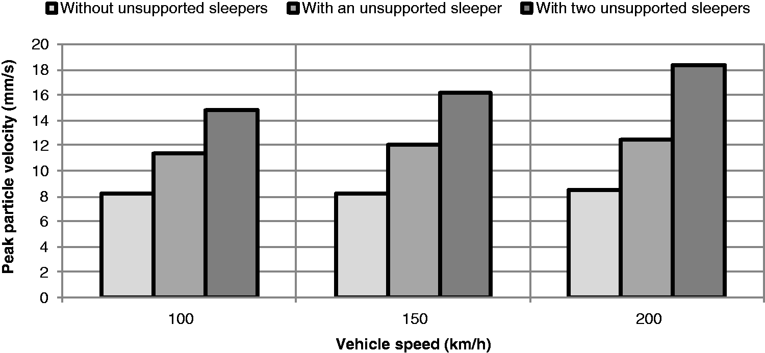
As can be observed from Figure 15, PPV increases 80.3, 96.5 and 116.8% when two unsupported sleepers exist in railway track in comparison to track without unsupported sleepers for vehicle speed 100, 150 and 200 km/h, respectively. In continuation, regression equations are derived between PPV and track parameters.
Derivation of regression equations between PPV and sleeper support parameters
Figure 16 illustrates the PPV versus track support stiffness for various track conditions.
Peak particle velocity for various distances. (a) Peak particle velocity at distance of 3 m from applied load, (b) peak particle velocity at distance of 6 m from applied load and (c) peak particle velocity at distance of 10 m from applied load.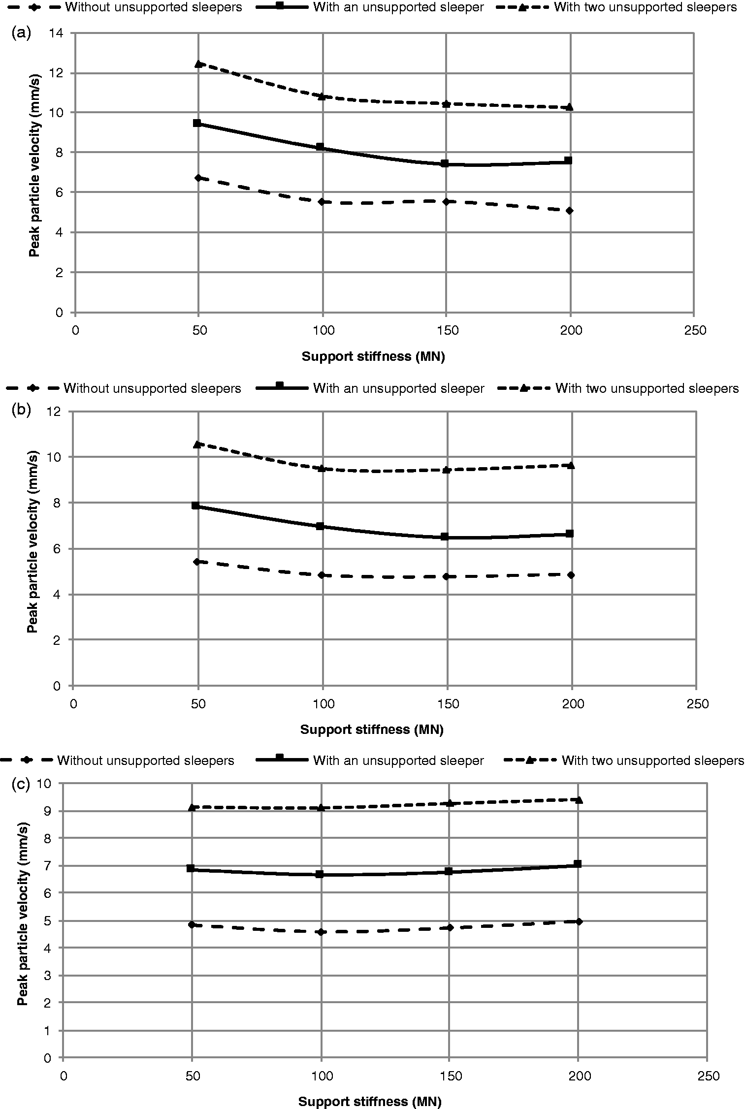
Derived regression equations at distance of 3 m from applied load.
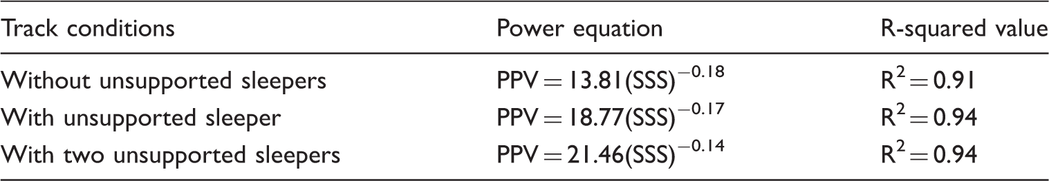
PPV: peak particle velocity.
Derived regression equations at distance of 6 m from applied load.
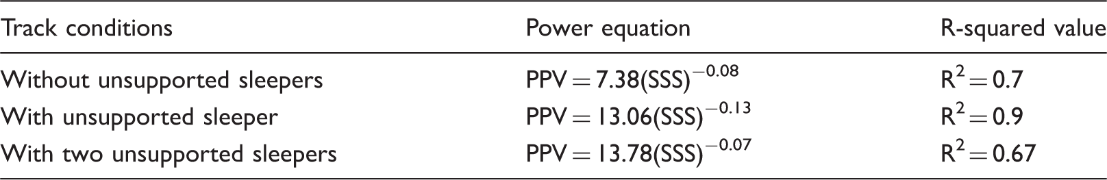
PPV: peak particle velocity.
Derived regression equations at distance of 10 m from applied load.
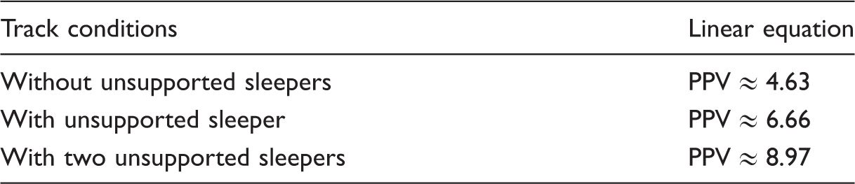
PPV: peak particle velocity.
As can be seen from these tables, the mathematical relations between PPV and support stiffness are non-linear and linear at distances of 3 and 10 m from applied load, respectively. Also, the track with unsupported sleepers has more vibration velocities than track without unsupported sleepers for all distances.
Conclusions
In this paper, the effects of unsupported railway sleepers on the environmental train-induced vibrations were investigated. In this regard, first the model of train–track dynamic interaction was described and validated. In continuation, the effects of track sleeper support on maximum support force were studied. Subsequently, a validated model of train-induced vibrations was presented based on the continuum FEM. The output of the first FEM model as the total support force including spring and dashpot forces was introduced to the second one as an input force. Subsequently, the effects of the mentioned track support conditions on the ground-borne vibrations were investigated. The results showed that the displacement of railway sleeper under the moving vehicle increased 93.2 and 232.9% when there was an unsupported sleeper in the railway track with respect to track without unsupported sleepers for track support stiffness 50 and 200 MN/m, respectively. Also, these values rose to 197.3 and 471% for track with two unsupported sleepers. The ratio of track support force in adjacent sleeper with two and one unsupported sleepers to it without unsupported sleepers under the moving vehicle was 1.4 and 1.78, respectively, when track support stiffness was 50 MN/m. Also, the maximum vibration velocity of ground surface increased 39.9 and 47.4% when an unsupported sleeper existed in the track comparing to track without unsupported sleepers for track support stiffness 50 and 200 MN/m, respectively, at distance of 3 m from applied load. As well as, these values rose to 85 and 101.15% for track with two unsupported sleepers. Moreover, the regression equations between the PPV and track support stiffness in bench points close to applied load were non-linear whereas by increasing the distance of bench points from the applied load, they tended to linear form.
Footnotes
Declaration of conflicting interests
The author(s) declared no potential conflicts of interest with respect to the research, authorship, and/or publication of this article.
Funding
The author(s) received no financial support for the research, authorship, and/or publication of this article.