
Abstract
The vibration problem caused by rail transit involves the dynamic interaction between the train, track, roadbed, and surrounding strata. Establishing a comprehensive numerical model that includes all these components is a complex task. Given the complexity of the problem, many related numerical simulation studies simplify the complete system by dividing it into two steps. In the two steps, two inconsistent models are established for the same roadbed-stratum system, which may lead to modeling discrepancies. To reveal these differences, this paper establishes both the Winkler foundation method model and the whole system mode for the same working condition. The simulation results are compared with the whole system mode as a benchmark to examine the discrepancies in the Winkler foundation method. The results indicate that the separate modeling approach of the Winkler foundation method may lead to a significant underestimation of vibration intensity, resulting in an overly optimistic prediction of vibrations.
Keywords
Highlights
• The whole system model of train-track-stratum coupled vibration and the Winkler foundation method model were established. • The differences in the calculation results between the whole system model and the Winkler foundation method model under load excitations of various frequencies are compared. • The differences in site calculation results between the whole system model and the Winkler foundation method model were compared. • Suggestions for improving the Winkler foundation method model are provided.
Introduction
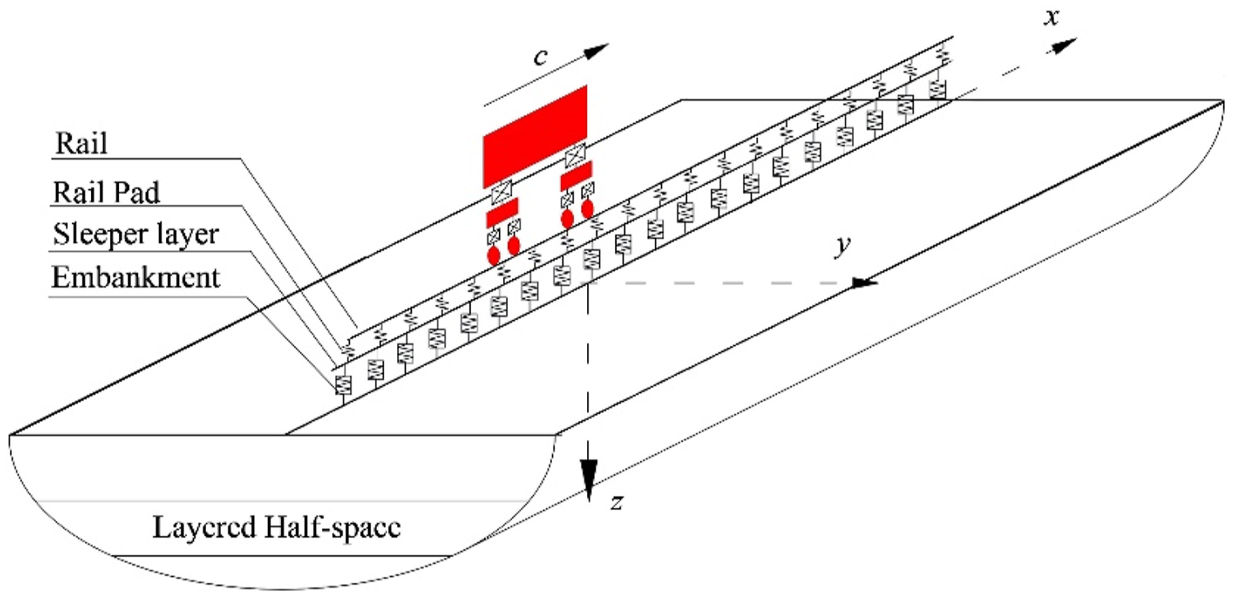
During rail transit operations, dynamic interactions always occur among three subsystems: trains, track structures, and the surrounding strata. The train subsystem moves, while the track and strata remain fixed in the earth reference system, which complicates the interaction problem and renders the system challenging to solve. Furthermore, compared to earthquake vibrations, vibrations induced by rail transit in rock and soil have higher frequencies and shorter wavelengths, necessitating detailed grid partitioning and extensive computational resources. In the past decade, domestic and international scholars1–6 have dedicated their efforts to developing a logically rigorous train-track-soil whole system coupled vibration model (referred to as the whole system mode, depicted in Figure 1). The essence of analyzing the whole system mode lies in situating the train, track, and soil within a moving reference frame synchronized with the train. In this framework, assuming uniform geometric conditions and physical properties of the track and soil at all times, the train-track-soil system forms a time-invariant structure, enabling a rigorous solution to the dynamic interaction problem. The whole system model of coupled train-track-ground vibration
7
.
The entire system model boasts rigorous logic, rapid computation speed, and facilitates convenient frequency domain random vibration analysis. However, it faces challenges in adhering to the time-invariant requirements of the surrounding line environment under typical operational conditions. When viewed from a moving train, any finite-length structure along the track direction (e.g., a station) renders the vibration system in the moving coordinate frame time-varying. Furthermore, the whole system model employs Fourier expansion and synthesis based on the superposition principle, which fundamentally isn’t suitable for nonlinear problems.
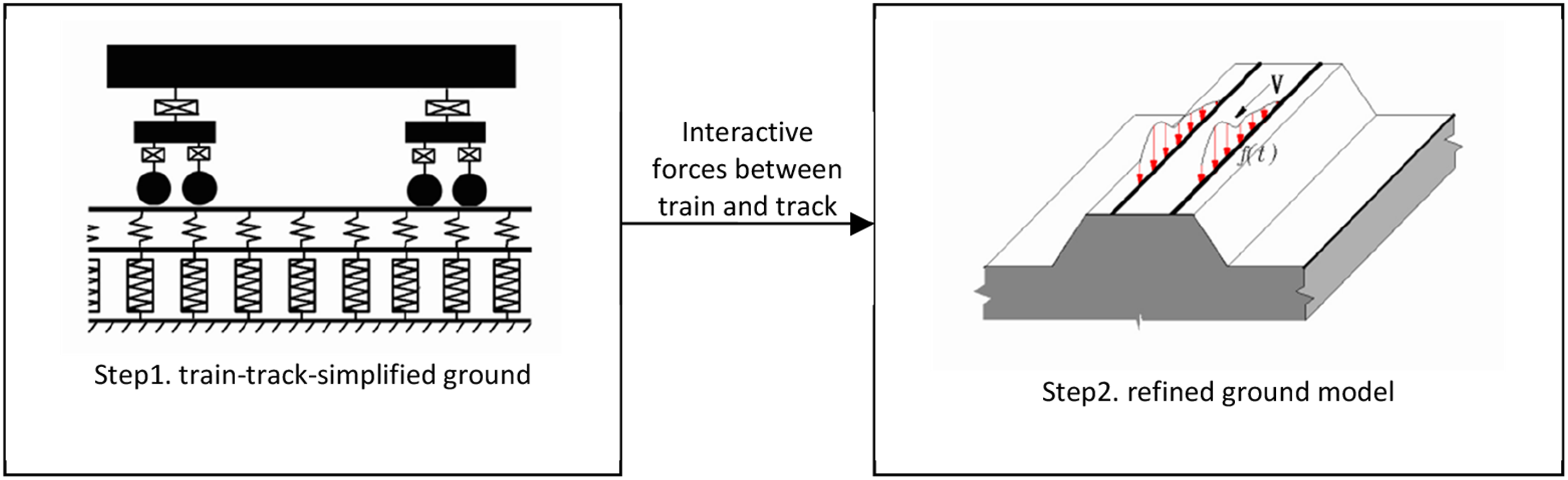
Therefore, for the numerical simulation of complex working conditions in specific engineering projects, many researchers8–18 have to divide the modeling process into two steps, as shown in Figure 2. The first step is to establish a “train-track coupled vibration model” to simulate the vibration of the train and track, and to calculate the interaction force between the wheel and rail (hereinafter referred to as the “wheel/rail force”). The train and track models within the system are relatively detailed, whereas the soil model is typically simplified to a Winkler spring model with damping effects. It is well understood that the Winkler foundation beam model can only represent the response of the beam itself and cannot capture the variations in the foundation beneath the beam. In order to simulate the soil response under and around the track, the second step of soil modeling must be carried out. In the second step, the soil model is replaced by layered half-space, finite element, finite difference and other models, and the load borne by the soil model is the wheel/rail force or Winkler foundation reaction force output in the first step. Winker foundation method modeling process
7
.
The step-by-step modeling approach effectively circumvents issues associated with time-varying systems. In the second stage of soil modeling, sophisticated numerical calculation software can be utilized to account for nonlinear and non-uniform actual operating conditions, and can even incorporate nearby buildings and structures into the model. However, for the same physical object (soil), each step establishes its own model. This approach is justifiable only if the Winkler foundation used in the first step is equivalent to the detailed soil model in the second step. To achieve this, researchers typically apply identical static loads to both the first-step Winkler foundation model and the second-step detailed soil model, and deduce the Winkler spring stiffness of the first step under conditions of equal displacement. 14 However, it raises questions about whether this equivalence under static conditions holds true for the dynamic interaction typical of train, track, and soil problems.
Existing studies have not systematically assessed the compatibility between wheel-rail forces calculated using the Winkler foundation method and those derived from more detailed soil models. Unlike previous research, which predominantly discussed the limitations of the Winkler foundation model qualitatively, this paper presents a comprehensive framework for quantitative error analysis. This framework encompasses critical factors such as train speed, wheel-rail force frequency, and the horizontal distance between observation points and the track, enabling a detailed evaluation of how these factors influence the accuracy of the Winkler foundation method’s calculations. The study is not limited to specific cases; instead, it systematically assesses the efficacy of the Winkler foundation method under various operating conditions. For this purpose, both a full system model and a Winkler foundation method model incorporating the Winkler foundation are established under the same operational setting. By comparing numerical results from the full system model, this study explores the impact of the Winkler foundation model on soil vibration outcomes and provides recommendations to mitigate or reduce these effects.
Whole system model of train-track-stratum coupled vibration
The whole system model employs Fourier analysis and synthesis. Initially, the wheel/rail random irregularities are decomposed into a series of harmonic components, after which the system’s response is calculated for each harmonic component. The overall system response is then determined by summing the responses of all harmonic components.
Assume that the wheel/rail vertical irregularity is a function z(x) along the track mileage coordinate x. k represent the spatial wave number distributed along the track direction x, and z(k) represent the wheel/rail irregularity in the wave number domain. Perform a Fourier series expansion of z(x) about the x coordinate. The equation is as follows

Under the n-th harmonic irregularity condition, when the train runs on the track at speed c, the train is subjected to vertical excitation. The frequency of the vertical vibrations of the train is

Observed in a reference frame moving horizontally with the train, if the geometric conditions and physical properties of the track and site remain constant over time, the train-track-site system is in a state of resonant dynamic interaction. In the moving reference frame, the Green’s function of the site groundsurface displacement is convolved to construct the dynamic flexibility of the roadbed; the track structure is simplified using a beam model; and the train is simplified using a mass-spring-damper model. The continuity conditions at the contact interfaces between the track, train, and roadbed are then considered to establish the coupled differential equations of the entire system. A spatial Fourier transform is performed along the track direction to convert the differential equation into an algebraic equation in the wavenumber domain. After decoupling, the interaction force between the track and the roadbed is determined, and subsequently, the vibration response of the roadbed site in the moving reference frame is obtained. After moving coordinate substitution, the frequency domain displacement response of any particle in the track, roadbed, and surrounding strata under the fixed reference system can be obtained as
According to the superposition principle, the displacement caused by all irregular components is given by


For the part of the system that moves with the train, the time domain response of random vibration equals the superposition of the resonant frequency components. For instance, the wheel/rail interaction force is

Construction of Winkler foundation method model
To facilitate comparison and highlight the problem, the whole system model shown in Figure 1 is artificially disassembled into a Winkler foundation method model, as shown in Figure 3. The Winkler foundation method model constructed in this way is as consistent as possible with the whole system model, and the only difference is that the stratum in the first step is different from that of the whole system model. As shown in Figure 3(a), in the first step, the stratum model is replaced by the damping spring of the Winkler foundation. When calculating the wheel-rail interaction force required for the displacement response Winkler foundation method model formed after the whole system model is split. (a) Simplified model of train-track-ground in the first step (b) Fine model of the track-ground in the second step.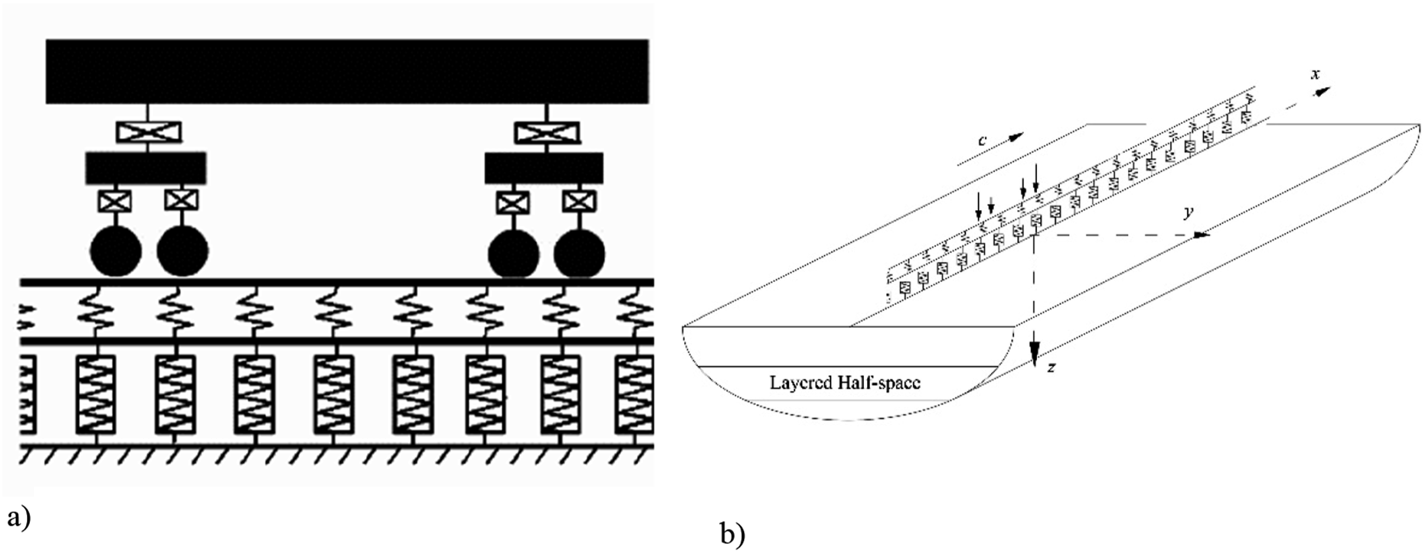

The calculation model of the second step is depicted in Figure 3(b), identical to the track-site model of the whole system. According to the fundamental principle of the Winkler foundation method, the consistency between the Winkler foundation in the first step and the layered half-space in the second step is ensured through the static equivalence method. 14 That is, the same vertical static load is applied to the rails, and the rail settlement values of the two models are calculated. The stiffness coefficient k s of the Winkler foundation is then determined based on achieving equal settlement values.
The wheel-rail force sequence P calculated in the first step is applied to the rail beam, and the vibration response of the roadbed site is computed using equation (4a and 4b). All other parameters are kept consistent with the whole system model to ensure that any discrepancies in the calculation results arise solely from the separate modeling approach of the Winkler foundation method.
Example parameters
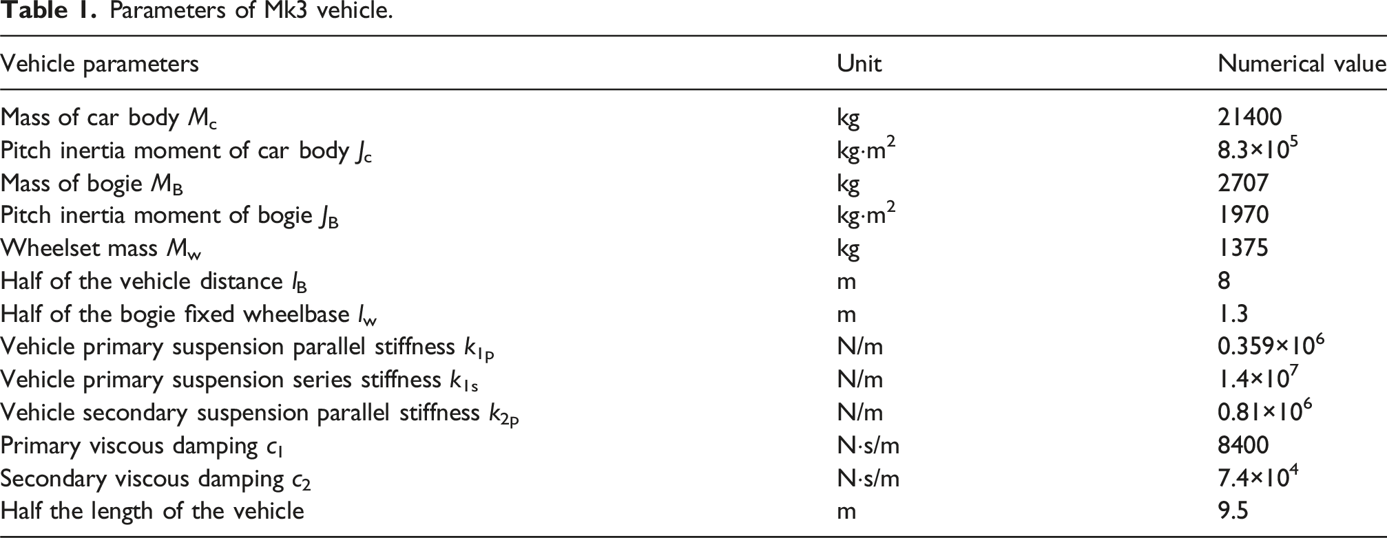
Parameters of Mk3 vehicle.
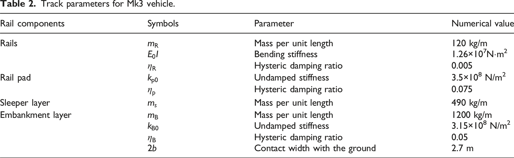
Track parameters for Mk3 vehicle.
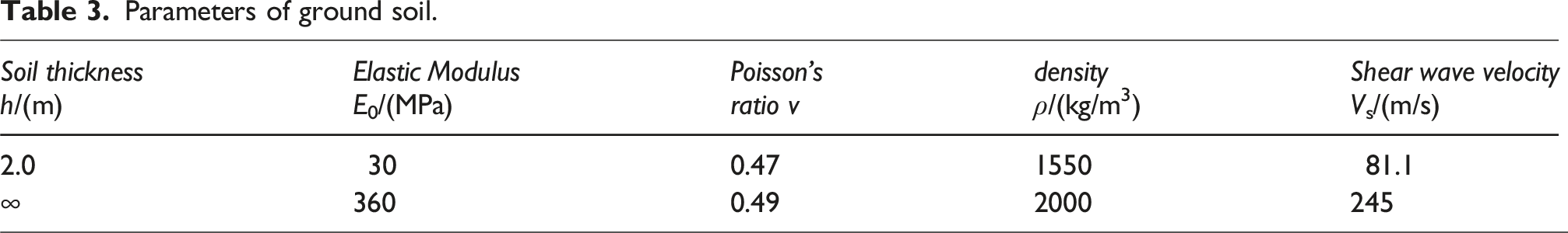
Parameters of ground soil.
Results and discussion
Roadbed vibration waveform
Assuming the amplitude of the harmonic irregularity between the wheel and rail is 1 mm, the excitation frequency Ω/2π received by the wheel axle due to wheel-rail irregularity is set at 0, 4, 8, 16, 31.5, and 63 Hz respectively. Here, 0 Hz denotes complete smoothness between the wheel and rail, with excitation resulting from the train’s weight, that is, quasi-static excitation. The vibration response of the roadbed soil is then calculated using equations (4a and 4b). Figure 4 illustrates the time history of vertical displacement for a mass point located at x = 0, y = 0, z = 0.2 m (directly beneath the centerline of the track, at a depth of 0.2 m below the ground surface). The reference time t = 0 corresponds to the moment when the first wheel pair passes directly above the mass point. The train speed is set at c = 25 m/s, equivalent to 90 km/h. Displacement time histories of the particle 0.2 m below the midline of the embankment/ground interface, the speed of the vehicle being 25 m/s.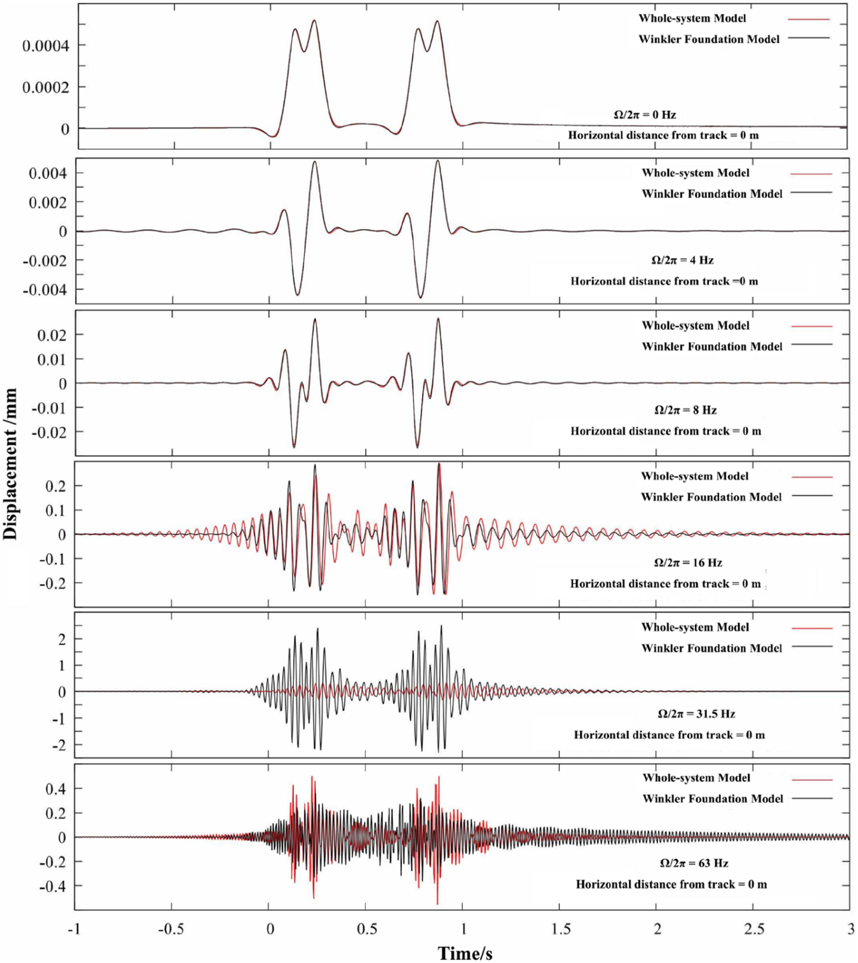
Under the influence of wheel-rail forces at frequencies of 8 Hz and below (resulting from wheel/rail irregularities with wavelengths ≥ 3.125 m), the two curves in the figure largely overlap. This indicates that for long-wave wheel/rail irregularities, the results computed by both the whole system model and the Winkler foundation method model are nearly identical, and any discrepancy introduced by the Winkler foundation method modeling can be disregarded. As the frequency increases to 16 Hz, slight differences appear between the results of the two models; however, these differences are not substantial. The Winkler foundation method’s site models demonstrate equivalence under static conditions at zero frequency and perform adequately at low vehicle speeds and low wheel-rail frequencies, aligning with expectations.
When the frequency reaches 31.5 Hz, the results obtained from the Winkler foundation method exhibit substantial deviations, which are significantly greater than those observed in the whole system model used as the reference. At 63 Hz irregularity, the deviations from the Winkler foundation method remain considerable. It is noteworthy that the peak value of the Winkler foundation method curve is notably lower than that of the whole system curve, suggesting that the Winkler foundation method modeling may underestimate roadbed vibrations.
To assess the model’s accuracy under high-speed conditions while maintaining other parameters unchanged, the speed was increased to 60 m/s (216 km/h), which is approximately equivalent to the typical speed of EMUs in China. Subsequently, the time history of roadbed vibration was computed. As depicted in Figure 5, for the 0 Hz, 4 Hz, and 8 Hz curves, despite the very low frequency of the wheel-rail force, the Winkler foundation method exhibits deviations and fails to maintain its good performance under conditions of long-wave irregularity. This occurs because, despite the low excitation frequency of the wheel-rail force, the rapid movement induces higher-frequency components in the roadbed vibration. These high-frequency components do not conform to the static equivalence condition of zero frequency, resulting in deviations in the roadbed vibration waveform. The time histories of subgrade vibration caused by wheel-rail forces at 31.5 Hz and 63 Hz in Figure 5 resemble those in Figure 4, both exhibiting significant model differences, with the vibration levels being underestimated particularly at 63 Hz. Displacement time histories of the particle 0.2 m below the midline of the embankment/ground interface, the speed of the vehicle being 60 m/s.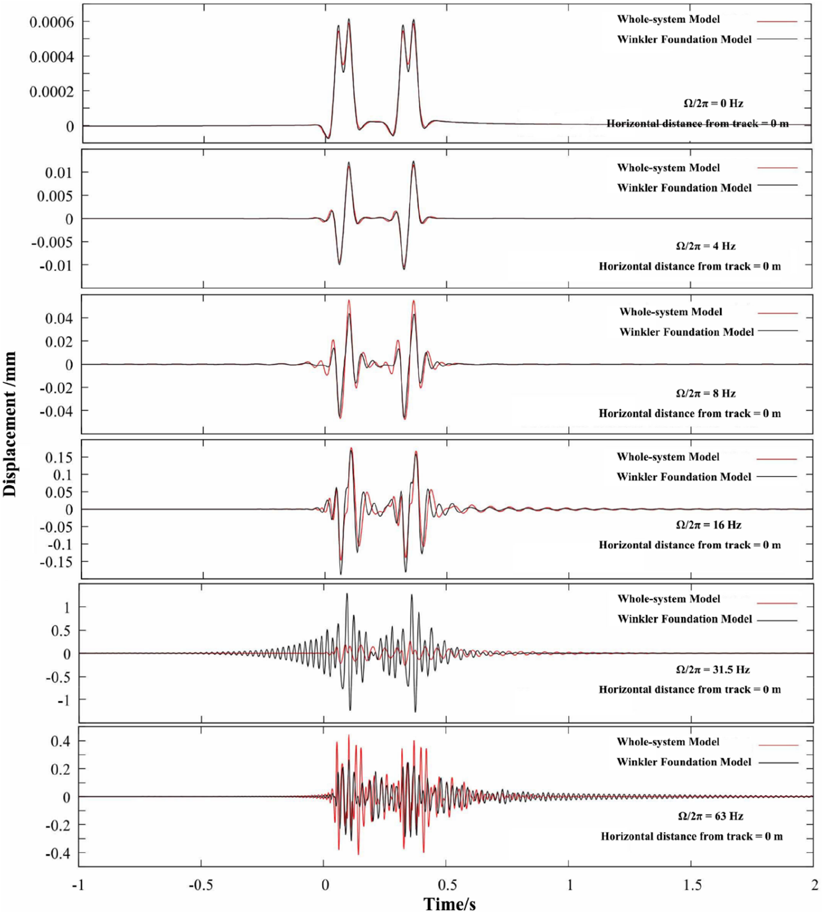
The train speed is further increased to 83 m/s, equivalent to 300 km/h, which matches the operating speed of China’s high-speed railway. The calculated dynamic response of the subgrade is depicted in Figure 6. Compared to Figure 5, the discrepancies in results from the Winkler foundation method are more pronounced for low-frequency wheel-rail forces of 16 Hz and below. The vibration waveform induced by the 31.5 Hz wheel-rail force shows less variation compared to low-speed operations but remains noticeably distorted. The waveform difference corresponding to the 63 Hz wheel-rail force is still quite significant, resulting in an overestimation of vibration intensity. Displacement time histories of the particle 0.2 m below the midline of the embankment/ground interface, the speed of the vehicle being 83 m/s.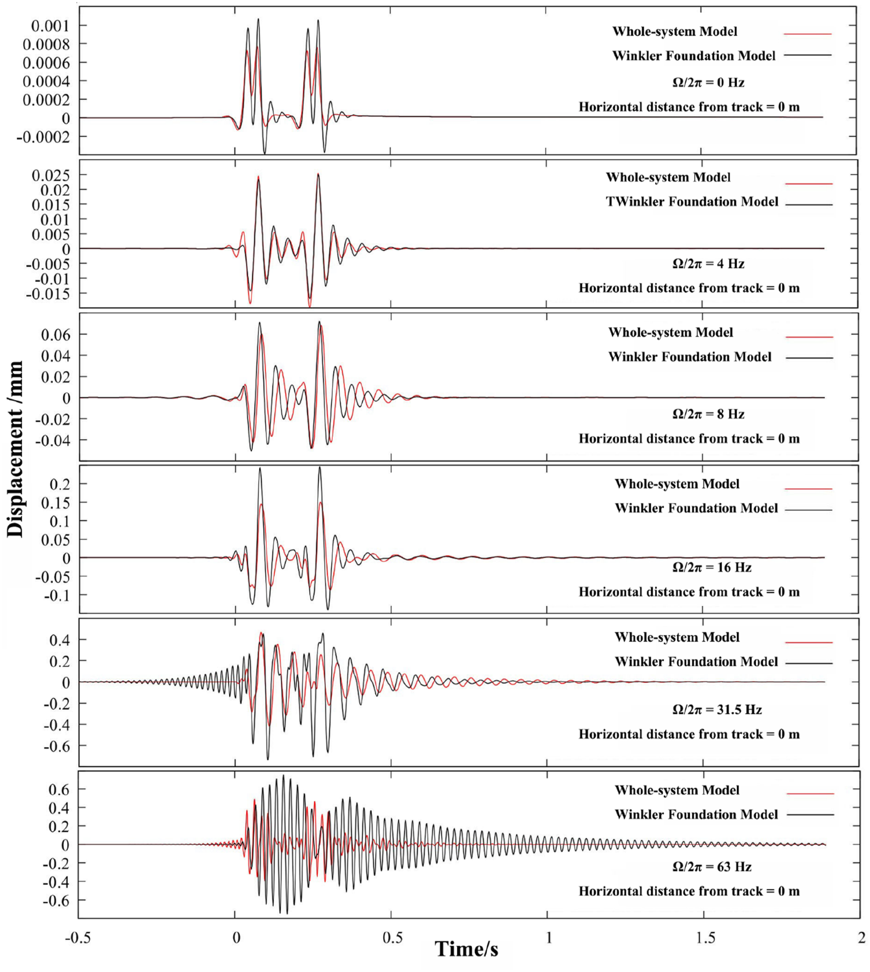
Figures 4–6 demonstrate that the Winkler foundation method exhibits minimal differences in calculating roadbed vibration induced by low-frequency wheel-rail forces. However, discrepancies become more significant when calculating roadbed vibration excited by medium- and high-frequency wheel-rail forces. Field measurements of traffic environment vibrations indicate that the upper limit of the main frequency range of vibrations approaches 80 Hz.19–22 The waveform deviations observed at 31.5 Hz and 63 Hz suggest that the isolated use of the Winkler foundation method for modeling may lead to significant discrepancies in simulation results.
Vibration waveform of the surrounding soil layer
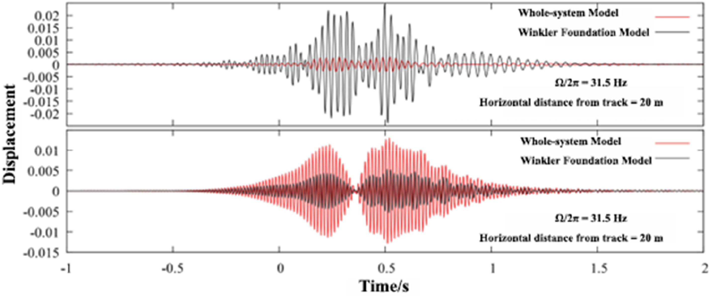
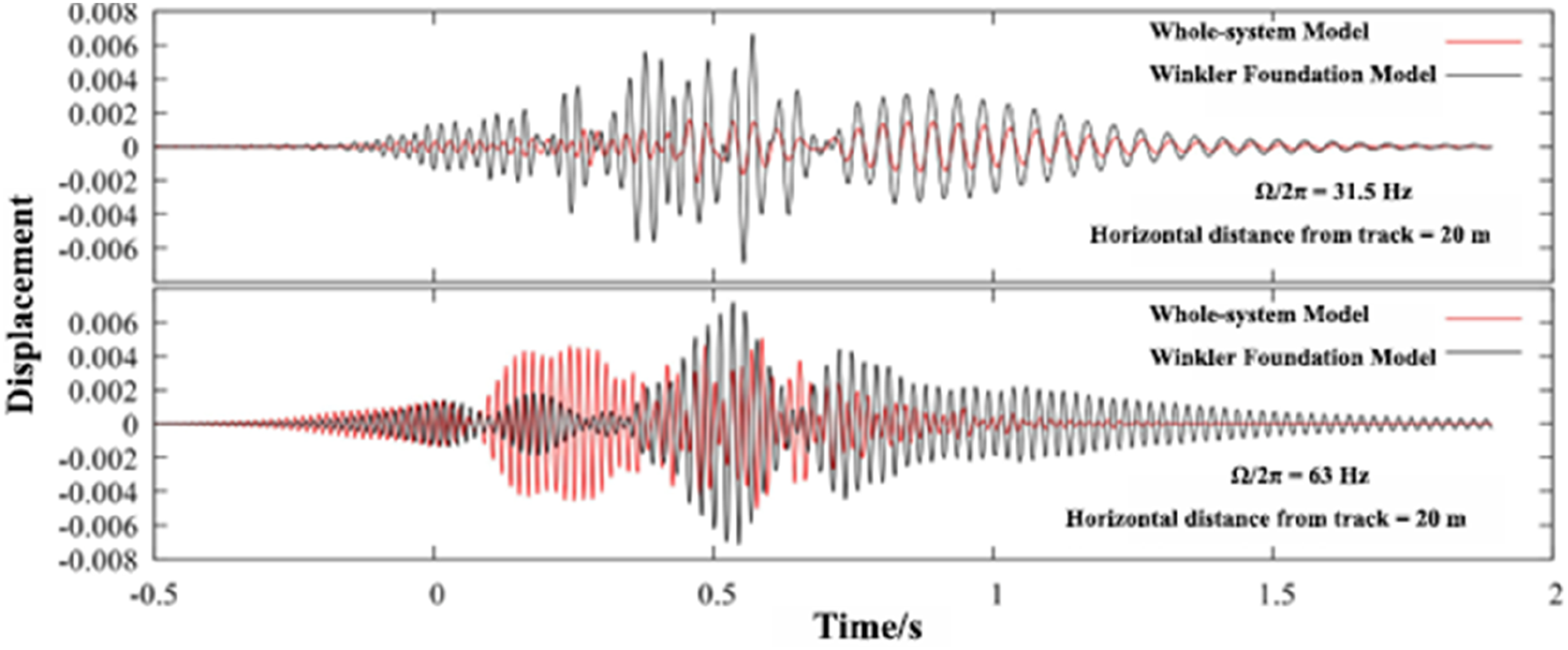
The calculation results also indicate that the deviation observed with the Winkler foundation method extends beyond just the roadbed area adjacent to the track; it also affects the ambient vibration of the surrounding site soil. Figures 7–9 display the time history curves of displacement at an observation point within the site at vehicle speeds of 25 m/s, 60 m/s, and 83 m/s, respectively. The observation point is located 20 m horizontally from the track centerline, with a burial depth of 0.2 m below the ground surface. It is evident that the vibration calculated at this position using the Winkler foundation method is entirely inconsistent with the benchmark value, showing a significant model discrepancy. Specifically, when the 63 Hz wheel-rail force operates at speeds of 25 m/s and 60 m/s, the Winkler foundation method yields significantly smaller results compared to the benchmark value obtained from the whole system method. This indicates that the Winkler foundation method modeling may not only underestimate the vibration intensity of the roadbed but also underestimate the vibration level of the surrounding site. This observation underscores the need for special attention. Displacement time histories of the particle 0.2 m below the ground surface, horizontal distances to the midline of the track = 20m, speed of the vehicle = 25 m/s. Displacement time histories of the particle 0.2 m below the ground surface, horizontal distances to the midline of the track = 20m, speed of the vehicle = 60 m/s. Displacement time histories of the particle 0.2 m below the ground surface, horizontal distances to the midline of the track = 20m, speed of the vehicle = 83 m/s.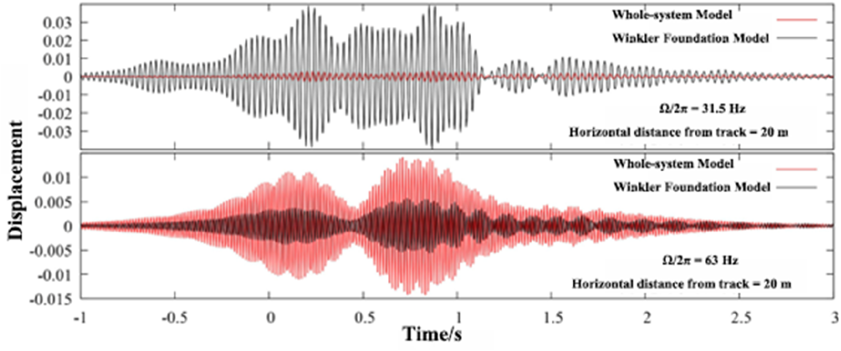
Distribution of Winkler foundation method model differences in subgrade and site
In order to quantitatively analyze the model differences of the Winkler foundation method and its distribution characteristics in the surrounding track site, let I represent the maximum absolute value of the vibration time history curve (vibration intensity). Define the relative difference of vibration intensity as follows
Among them, I1and I2 represent the vibration intensity calculated by the whole system model and the Winkler foundation method model, respectively.
Figure 10 illustrates the relative differences in vibration intensity at a depth of 0.2 m below the ground within a 140 m range from the track, considering a train speed of 25 m/s and wheel-rail excitation frequencies of 0, 4, 8, 16, 31.5, and 63 Hz. Modeling errors of vibration intensity of soil 0.2 m below the ground surface, vehicle speed = 25 m/s.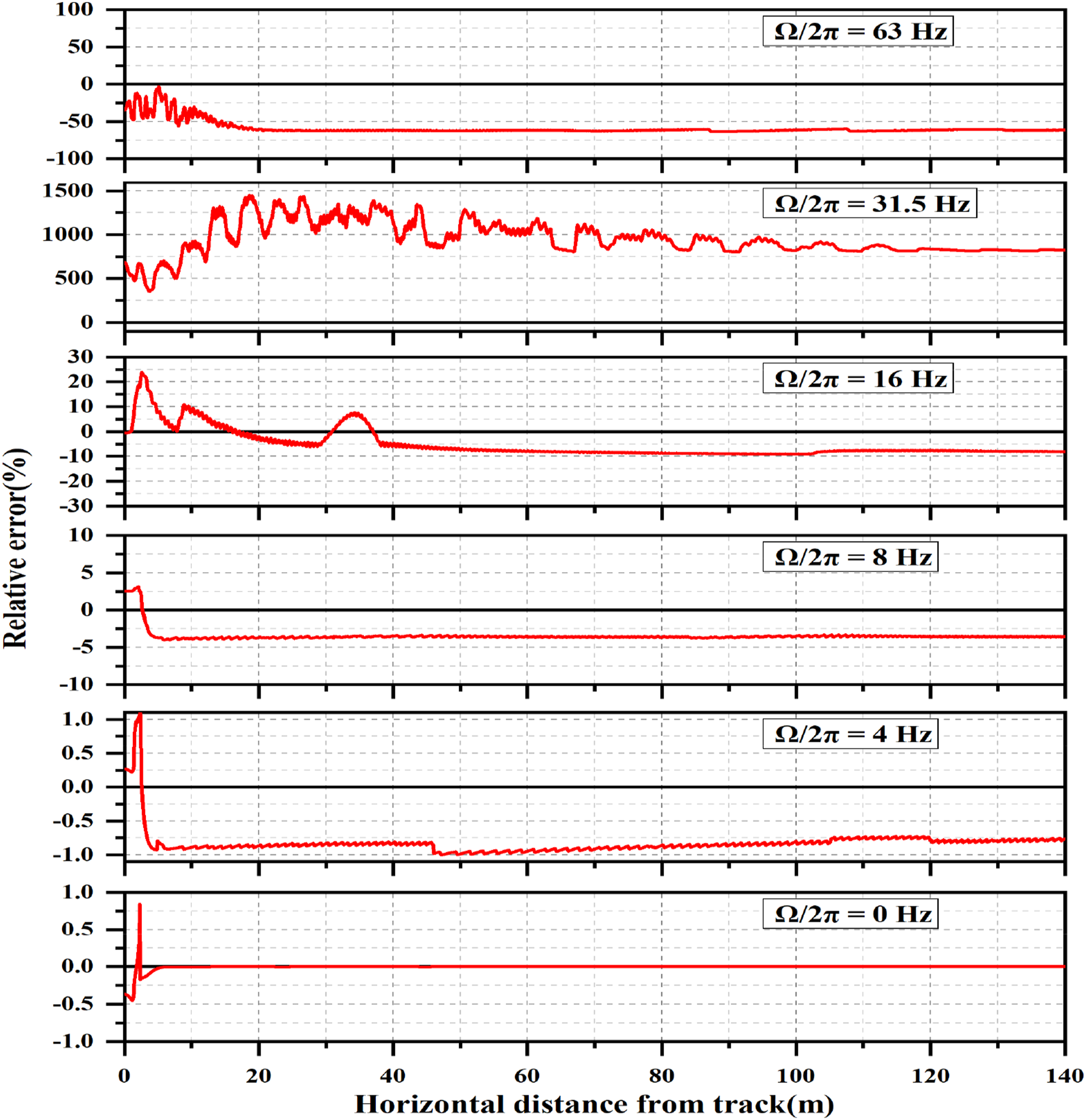
Under the quasi-static wheel-rail force with a frequency of 0 Hz, the site vibration calculated by the Winkler foundation method shows negligible differences, not exceeding 1% near the track and approaching zero 5 m away. With a wheel-rail force frequency of 4 Hz, the maximum difference reaches 1.1%, and there is a slight underestimation of site vibration at greater distances, albeit the difference remains minimal.
When the wheel-rail force frequency increases to 8 Hz, the Winkler foundation method slightly underestimates the site vibration by approximately 4% at a distance of 2 m, with the maximum difference noted. However, as the wheel-rail force frequency reaches 16 Hz, the Winkler foundation method exhibits an overestimation of the vibration in the roadbed area near the track, with a difference approaching 24%. Conversely, it underestimates the vibration in the far-field, showing a difference of nearly 10%.
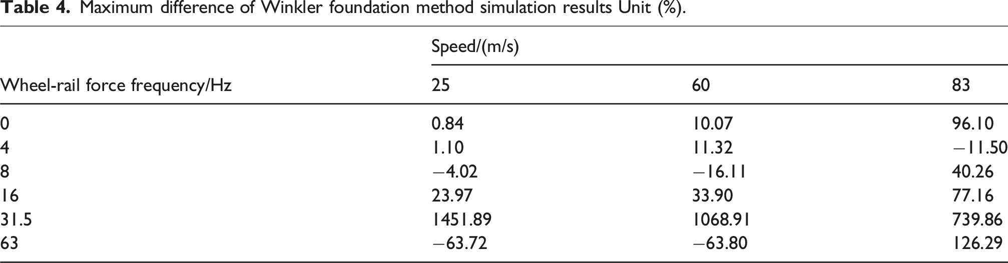
Under the condition of a wheel-rail force frequency of 31.5 Hz, the vibration intensity calculated by the Winkler foundation method exhibits significant discrepancies across all areas, with the maximum value exceeding 1450%. This renders the numerical simulation meaningless and could lead to misleading conclusions. For the high-frequency wheel-rail force of 63 Hz, the Winkler foundation method underestimates the vibration levels of both the roadbed and the surrounding site, with differences exceeding 60% at a distance of 20 m.。
Based on the comprehensive results obtained from low-speed trains, the shortcomings of the Winkler foundation method extend beyond the vibration estimation of the roadbed to include significant discrepancies in site vibrations across greater distances. While the method shows reasonable accuracy under low-frequency wheel-rail forces, it exhibits considerable inaccuracies under high-frequency conditions, sometimes resulting in overestimations exceeding tenfold or underestimations exceeding 60%. Therefore, caution should be exercised when considering the applicability of the Winkler foundation method for such scenarios.
The discrepancies of the Winkler foundation method at a speed of 60 m/s are illustrated in Figure 11. When considering 0 Hz wheel-rail excitation, the variances in the roadbed area are slightly more pronounced compared to lower speeds, peaking at 10%; however, these discrepancies diminish rapidly to nearly zero beyond 3 m from the track. The subgrade vibration under 4 Hz wheel-rail excitation was overestimated by approximately 11%; however, the site vibration 5 m away from the track showed a slight underestimation with a minimal difference. Under 8 Hz wheel-rail excitation, the subgrade vibration was underestimated by around 16%, and the site vibration 10 m away was similarly underestimated, showing a difference of over 7%. At 16 Hz wheel-rail force, the largest difference occurred at a distance of 5.5 m from the track, nearing 34%; this difference gradually diminished with distance, turning negative at 40 m away and resulting in an underestimate of about 10%. The issue with the Winkler foundation method under 31.5 Hz wheel-rail force is highly significant, with differences ranging from a minimum of 214% to a maximum exceeding 1000%. Under 63 Hz wheel-rail force conditions, both subgrade and site vibrations are underestimated, with differences reaching up to 64%. Compared to the low-speed train at 25 m/s, except for the 31.5 Hz wheel-rail force, the maximum differences increase, indicating deteriorating simulation results for the Winkler foundation method. Modeling errors of vibration intensity of soil 0.2 m below the ground surface, vehicle speed = 60 m/s.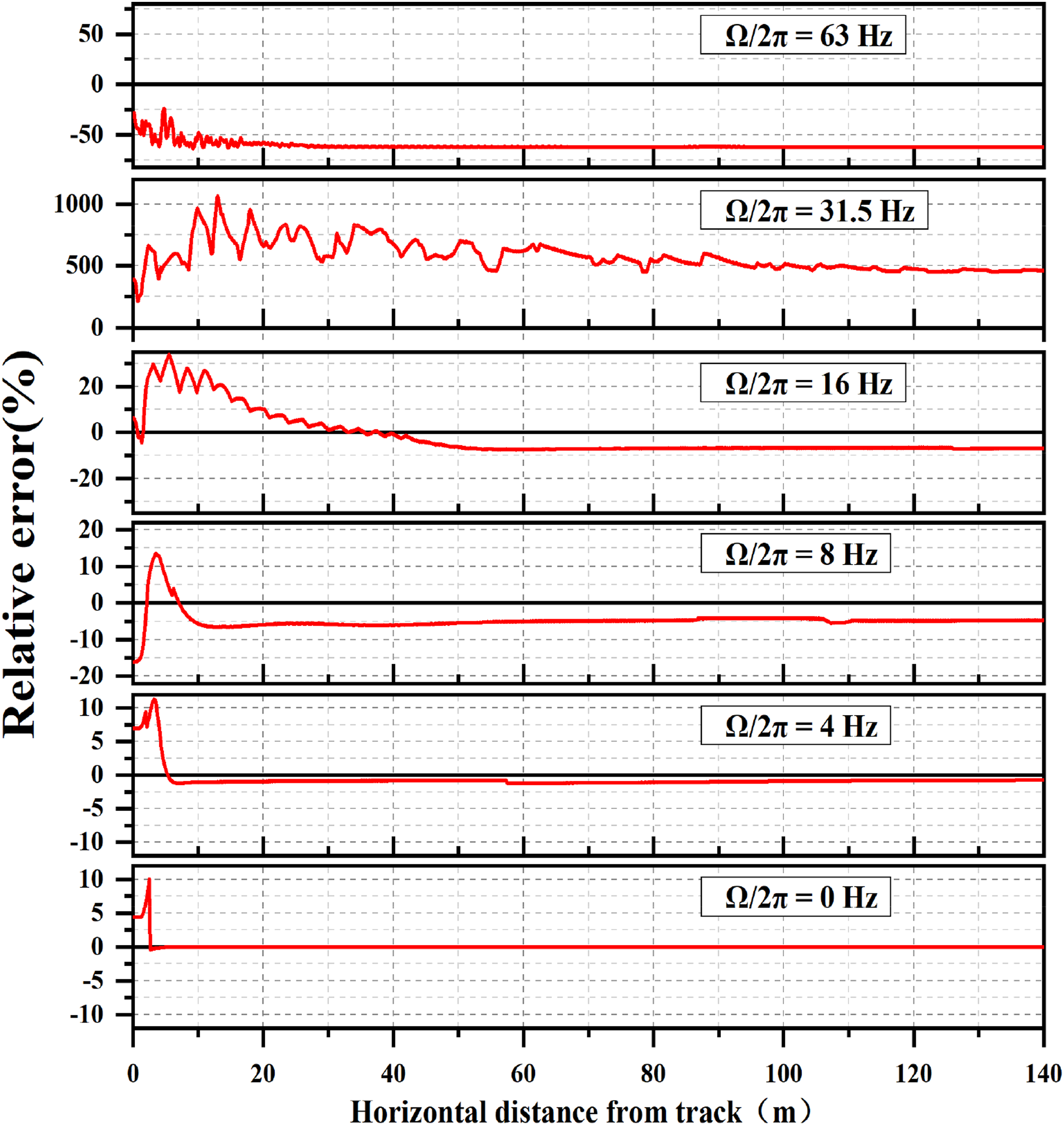
Figure 12 illustrates the discrepancies in the Winkler foundation method’s calculations for high-speed railways at 83 m/s. Even under quasi-static wheel-rail forces, the differences in the roadbed area are significant, exceeding 96%. Specifically, the roadbed vibration under 4 Hz wheel-rail force is underestimated, with a maximum difference of 11%, while vibrations at sites beyond 7 m are similarly underestimated, with a maximum difference of 11.5%. The vibration difference in the subgrade under the 8 Hz wheel-rail excitation is small. However, the vibration difference at a site 6.3 m away reaches 40%, and it is underestimated at a distance of 10 m. Under the 16 Hz wheel-rail force, the vibration difference in the subgrade and nearby site is significant, with the maximum value reaching 77%. The vibration difference at a distance of 20 m is minimal. The vibration difference in the roadbed area under the 31.5 Hz wheel-rail force is approximately 60%, while the disparity in the distant site exceeds 700%. Near the track, the maximum vibration difference under the 63 Hz wheel-rail force exceeds 126%, with significant underestimation in the distant areas reaching over 75%. As depicted in Figure 12, when the vehicle speed meets or exceeds the Rayleigh wave speed of the site, the Winkler foundation method modeling yields substantial discrepancies, rendering the model output unreliable. Modeling errors of vibration intensity of soil 0.2 m below the ground surface, vehicle speed = 83 m/s.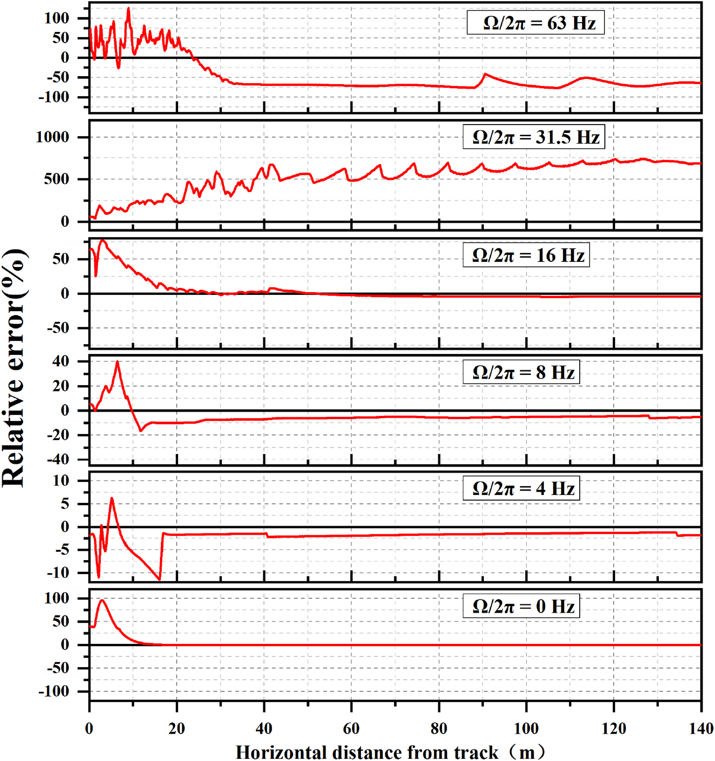
Maximum difference of Winkler foundation method simulation results Unit (%).
Recommendations for eliminating or reducing Winkler foundation method modeling discrepancies
The fundamental reason behind the discrepancies in the Winkler foundation method’s calculations stems from the inconsistency between the site models in the preceding and subsequent steps. Specifically, the dynamic flexibility H of the roadbed varies with both the wheel-rail force frequency Ω and the vehicle speed c. However, the mechanical properties of the Winkler foundation are independent of both frequency and vehicle speed. The bed coefficient, determined under static equivalent conditions, corresponds to a wheel-rail force frequency and vehicle speed that are both equal to zero. In the whole system model, the dynamic flexibility H of the layered half-space embankment is related to the frequency-wavenumber domain Green’s function G(β,γ) of the site.
23

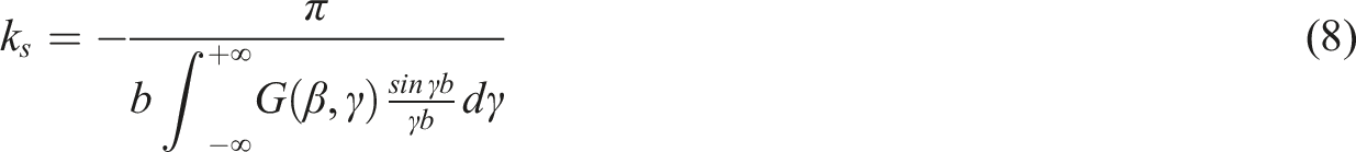
If equation (8) holds, the Winkler foundation method is completely equivalent to the whole system method. In reality, static equivalence is merely a special case of equation (8) where the wheel-rail force frequency Ω and the train speed c approach zero. In the limit as Ω and c tend to 0, the dynamic wave number effect diminishes, and β no longer represents the actual propagation wave but degenerates into an integration variable for static solutions; the stiffness obtained ultimately is equivalent to the static case stiffness.
Equation (8) provides the means to calibrate the Winkler foundation method model. First, the Green’s function of the second-step site model must be obtained. Then, the foundation coefficient ks(Ω, c) under different wheel-rail force frequencies and vehicle speeds must be determined through integral calculation. This allows for the system solution of the first step to be performed.
It should be noted that for relatively regular sites, such as those with horizontal layers and 2.5-dimensional changes, the numerical Green’s function can be calculated using transfer matrix, finite element, and boundary element methods. However, for complex sites with three-dimensional changes, the load-bearing body becomes a time-varying system in the moving coordinate system. In such cases, the Green’s function in equation (8) cannot be obtained accurately and can only be approximated in the fixed coordinate system.
Moreover, when the construction site’s soil layer is relatively uniform, without noticeable weak interlayers or significant stratification, the soil can be simplified to a single layer. Since actual soils are often not completely homogeneous, if there are local variations or conditions where the upper layer is harder and the lower layer is softer, the Winkler model may lead to an overestimation or underestimation of vibration intensities. It is recommended to determine the soil’s equivalent spring stiffness and damping coefficients through static or low-frequency tests or using existing empirical formulas. When the soil layer exhibits a clear stratified structure, such as the top 2 m being clay and the lower part sand, the soil can be divided according to the main segments, each assigned different Winkler spring stiffness and damping. Numerical simulations should then treat each unit or zone segmentally. However, simplifying multiple layers often overlooks the wave transmission characteristics at the soil layer interfaces. If there is a significant stiffness or density gradient between layers, it can introduce additional errors. For sites with many layers and large variations, it is best to use multi-parameter correction methods, such as establishing a database for layered soil equivalent stiffness, and then make corrections within the frequency or time domains.
When the modulus of deformation of the soil layer is low, damping is high, and wave speed is low, the soil layer often exhibits significant nonlinearity under dynamic loading, and the low wave speed means that the attenuation of high-frequency components in the near field may not be rapid. Relying solely on static equivalent stiffness for calibration often underestimates the amplitude of mid- to high-frequency vibrations. Therefore, if involving high-speed trains or a higher-frequency range, it is advisable to consider dynamic testing or use frequency-dependent stiffness correction methods for calibration.
When the soil deformation modulus is high, damping is relatively low, and wave speed is high, the soil, due to its high stiffness, may correspond closely to the real situation in the mid- to low-frequency range with the Winkler model. However, at high frequencies or train speeds approaching wave propagation speed, soil inertia effects can lead to mismatches with simplified models. Therefore, it is possible to reduce the static-dynamic correction difference for hard soil sites, but when train speed approaches the wave speed of the soil layer, it is necessary to consider the overall system model to avoid errors that can be multiple times higher. If there are soft soils or other interlayers beneath the hard soil layer, it is necessary to treat the layers separately and pay attention to the interface effects between layers.
If the thickness of the soil layer is significantly greater than the depth affected by vibrations, the dynamic stress field induced by rail transit may only affect the upper part of the soil. In this case, the Winkler model is not sensitive to the effects on deeper soil layers, and model errors are primarily concentrated in the near-surface layers. When the site has a shallow rock face or a thin overlying soil layer, vibration waves can easily transmit to the bedrock layer, which exhibits higher stiffness. The Winkler model may underestimate the amplification effects caused by wave reflections at the soil-rock interface.
Conclusion
Since the whole system model of train-track-site coupled vibration struggles to accommodate certain complex working conditions, the Winkler foundation method, which employs separate modeling, is widely utilized in numerical simulation research of roadbed site vibration. The primary issue with the Winkler foundation method lies in establishing two distinct mechanical models for the same geotechnical site in two steps, leading to discrepancies in the simulation results.
Model differences have the following characteristics: (1) The discrepancies between the models using the Winkler foundation method are evident not only in the roadbed vibrations directly adjacent to the track but also in vibrations occurring in areas far from the track. (2) For low-speed trains, the Winkler foundation method can yield satisfactory simulation results under long-wave irregularities (low-frequency wheel-rail forces). However, significant differences between the subgrade and site vibrations become apparent in the short-wave section of wheel/rail irregularities (high-frequency wheel-rail forces). (3) For high-speed trains, calculation differences are more frequent and pronounced compared to low-speed trains. At certain frequencies of wheel-rail force excitation, the calculation results of the Winkler foundation method deviate from the benchmark values by orders of magnitude, rendering the simulations meaningless and potentially leading to misleading conclusions. (4) It is crucial to emphasize that the separate modeling approach using the Winkler foundation method may significantly underestimate vibration intensity. This could result in overly optimistic predictions of vibrations in rail transit environments.
The effective performance of the Winkler foundation method under conditions of low vehicle speed and low-frequency wheel-rail forces stems from the equivalence of the two site models under static conditions at zero frequency. The high-speed movement of the train generates high-frequency components in the site due to the wheel-rail forces. Under these conditions, the static equivalence cannot ensure the equivalence of the two site models, leading to significant differences in site vibration.
In light of the model differences observed with the Winkler foundation method, it is strongly recommended to calibrate the bed coefficients of the first-step site model based on the Green’s function of the second-step site model, taking into account the influence of train speed.
Footnotes
Author contributions
D. Li: Formal analysis, Data curation, Investigation, Methodology, Software, Visualization, Writing - original draft; H.K. Wang: Data curation, Investigation; J.L. Yin: Data curation, Investigation; Z.J. You: Data curation, Investigation; Q Xu: Data curation, Investigation. F.T. Wang: Funding acquisition, Resources, Project administration.
Funding
The author(s) disclosed receipt of the following financial support for the research, authorship, and/or publication of this article: This work was supported by the Scientific Research Fund of the Institute of Engineering Mechanics, China Earthquake Administration (Grant No. 2021D32),the Research and Development Project of Heilongjiang University (No. 22135), the Heilongjiang Province Ecological Environment Protection Research Project (No. HST2023JC010).
Declaration of conflicting interests
The author(s) declared no potential conflicts of interest with respect to the research, authorship, and/or publication of this article.
Data Availability Statement
The data that support the findings of this study are available from the corresponding author, [F.T. Wang], upon reasonable request.