Abstract
This paper addresses a theoretical control approach and its corresponding experimental validation for low-frequency active damping and isolation of a six-degree-of-freedom platform using high-resolution inertial sensors. Six vacuum-operating inertial sensors are placed on top of the platform to actively control it. Three of them measure displacements in horizontal directions and three in vertical directions. The resonance frequencies of the vertical and horizontal sensors range between 0.3 and 0.7 Hz with a resolution of
Keywords
Introduction
After the first detection of gravitational waves in 2015,1,2 a new era in understanding the universe began. To make such detection possible, gravitational wave detectors are required to operate in an ultrastable environment that can only be obtained by isolating them from external disturbances. Active isolation control is a major approach in this context as it was successfully implemented in LIGO’s (Laser Interferometer Gravitational-Wave Observatory) positioning platform,3,4 where it is possible to obtain amplitude spectral densities lower than
To the best of the authors’ knowledge, all six-degrees-of-freedom active vibration isolation platforms that operate effectively at low frequencies (particularly below 1 Hz) rely on relative displacement sensors in alongside inertial sensors. This approach is standard in high-end systems such as the Advanced LIGO seismic isolation platforms, 4 and the AEI-SAS platform, 6 all of which use capacitive or optical displacement sensors to measure relative motion between the isolated payload and the base. These measurements are essential not only to overcome the poor signal-to-noise ratio and high 1/f noise of inertial sensors at low frequencies but also to mitigate the effects of tilt-horizontal coupling, a well-known limitation in horizontal inertial sensors. Furthermore, these platforms typically implement control loops in the Cartesian frame, where sensor signals are transformed into global translational and rotational degrees of freedom. By combining inertial sensors for mid- to high-frequency control with relative displacement sensors for low-frequency feedback, these platforms achieve broadband isolation with high stability. In contrast, the main difference in this platform is that it is (1) investigating active isolation using only optical inertial sensors with (2) a decentralized collocated approach for closing the control loops. (3) Compared to existing platforms, the isolation system proposed in this paper is also modular by design, which means that it can easily accommodate a large variety of payloads.
The following sections of this paper discuss the concept of inertial control (precision control approach used for active isolation and disturbance rejection) for a one-degree-of-freedom system, followed by the working principle of inertial sensors, sensors used to isolate the six-degrees-of-freedom platform and their resolution. Then modeling, model tuning of the six-degrees-of-freedom platform and its correlation with the experimental data are discussed. Then the MIMO (Multiple-Input Multiple-Output) inertial control approach that is used to isolate the platform in all six degrees of freedom is introduced, and finally, the last two sections introduce experimental performances and practical limitations of the active isolation of the platform.
Inertial control
Active inertial control is a feedback control concept that is widely used in instrument isolation applications.
7
To exemplify it, consider a one-degree-of-freedom system where a mass m is connected to a spring with stiffness k, a damper with damping constant c, and an actuator that applies a force equal to a defined input command (Figure 1). Sketch showing the principle of an inertial control for one-degree-of-freedom system. 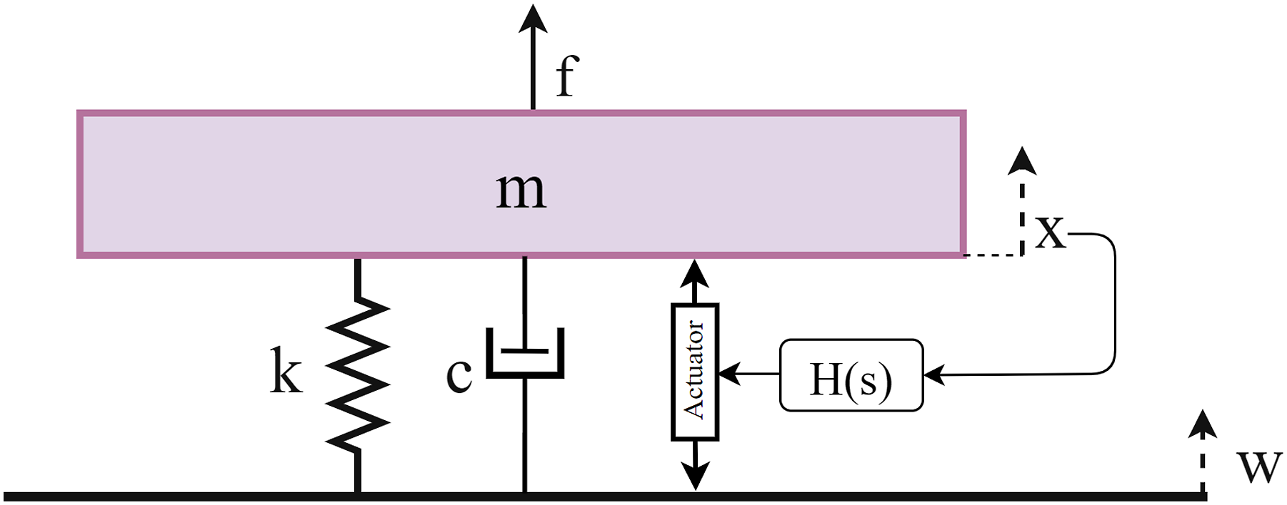
Two external disturbances, f denoting external forces applied on m and w denoting the displacement of the ground induce an undesirable displacement x of the payload mass m. By deriving the equations of motion, it is possible to get the transfer function from external disturbance force f to mass displacement x (compliance transfer function) and the transfer function from ground motion w to mass displacement x (transmissibility transfer function):


Active inertial isolation is based on feeding back the absolute displacement x of m into the actuators so that the actuator applies a force in the opposite direction of x and pushes it to lower values. Moreover, when including a feedback controller H(S) and deriving the equations of motion, closed-loop compliance and transmissibility transfer functions can be written as:


Equations (3) and (4) imply that the closed-loop transmissibility and compliance transfer functions converge to zero as the controller gain tends to infinity. So, when applying controllers with high gains, the payload is less sensitive to external force disturbances and transmitted ground motion, and consequently, the payload is isolated from these disturbances.
The transfer function from actuation force to displacement x of the one-degree-of-freedom system (Figure 1) constitutes a pair of complex poles and a phase starting around 0° before the resonance frequency and converging to 180° at high frequencies. So, a proportional derivative controller is a reasonable choice to ensure high loop gain before the resonance while guaranteeing a good phase margin because of the phase lead introduced by the derivative term around the crossover frequency. Taking into account, for example, the parameters m = 1 kg, k = 10 N/m and c = 0.1 Ns/m, the following PD controller is used:

Closing the loop using Eq. (5) facilitates damping the system’s resonance at 0.5 Hz and isolating the payload for one order of magnitude between frequency response at s = 0 (DC) and the vicinity of the system’s resonance (Figure 2). Magnitude of transfer functions from ground motion 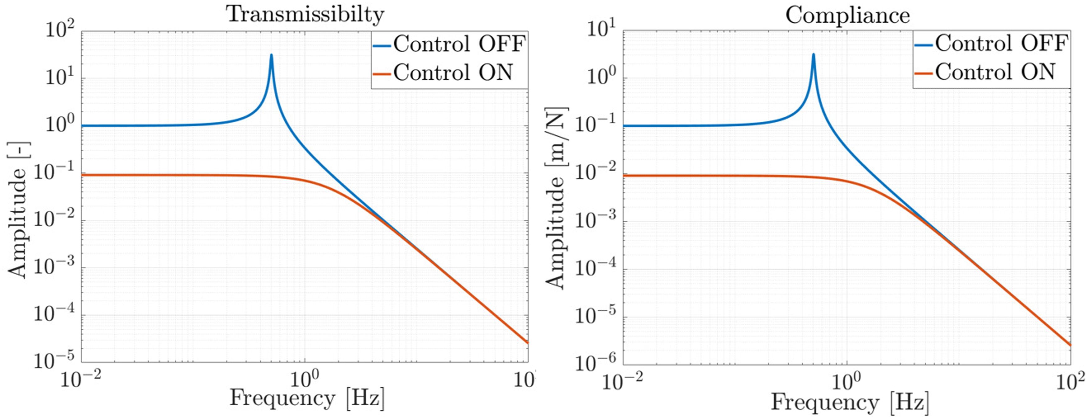
This implies that with inertial control, the mass m is ten times less sensitive to external force excitation or ground motion for frequencies between DC and 1 Hz. However, it is not straightforward to measure low-frequency absolute displacement x, so optical inertial sensors are used to approximate it. The concept of these sensors and their resolution are presented in the following section.
Optical inertial sensor
Inertial sensors are one-degree-of-freedom oscillators that return the relative displacement between the sensor’s base and an oscillating mass as an output. Assuming a simple inertial sensor that has a mass m
IS
, stiffness k
IS
, and damping constant c
IS
as shown in Figure 3, and by deriving the equations of motion, it is possible to write the sensitivity transfer function from the absolute displacement of the base of the inertial sensor x(s) to the output of the inertial sensor y
IS
(s) as follows
8
: Sketch showing the principle of an inertial sensor. 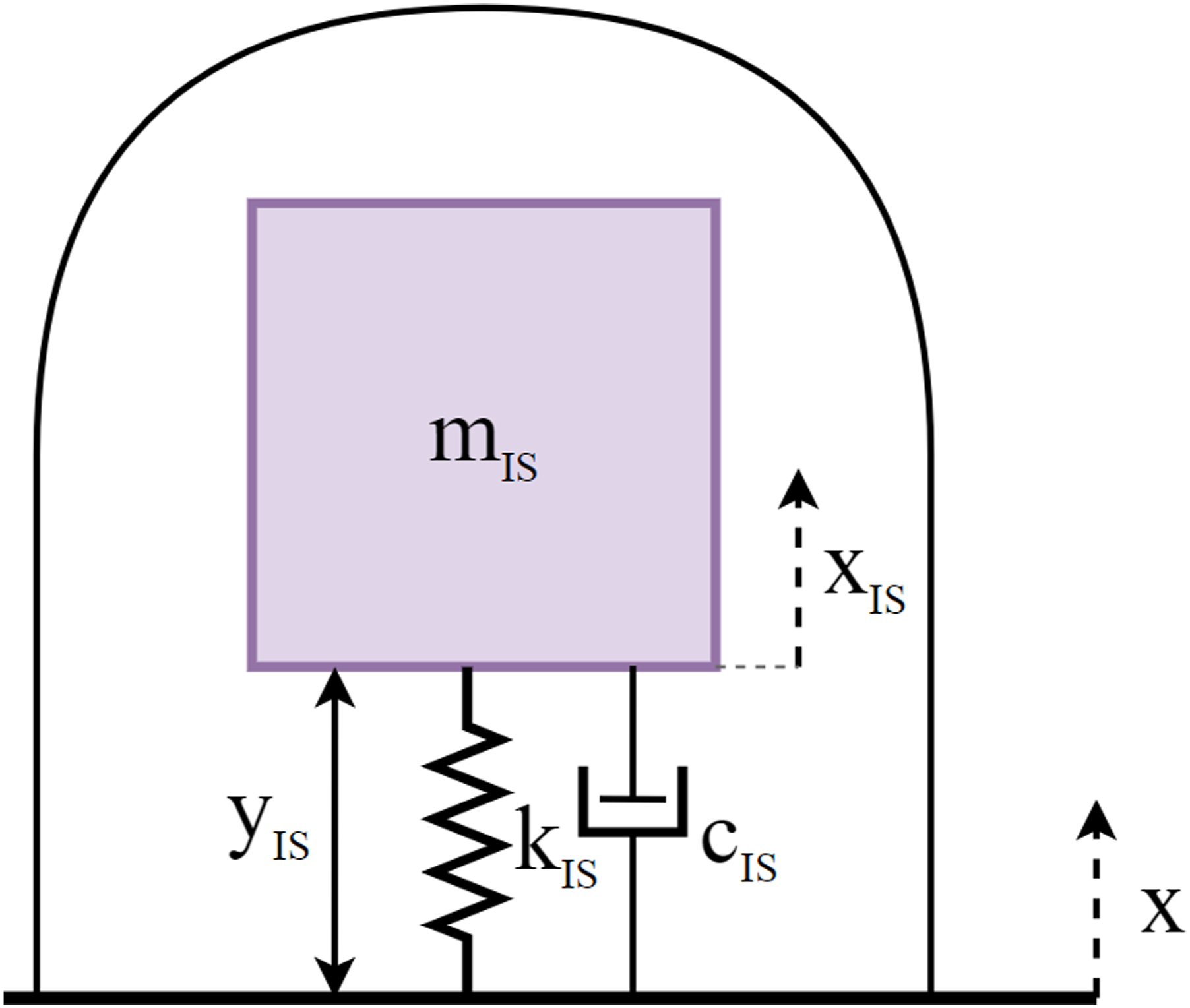

The sensitivity transfer function shows that for frequencies higher than the sensor’s resonance frequency
To actively isolate the six-degrees-of-freedom platform, an optical horizontal inertial sensor (HINS) and an optical vertical inertial sensor (VINS) were studied and developed in Ref. 9. These inertial sensors are one-degree-of-freedom pendulums where an interferometric readout is deployed to measure the relative mass displacement. In this particular case of HINS and VINS, Michelson interferometric readouts are used to ensure a resolution of around Resolution of the horizontal inertial sensor (HINS) and the vertical inertial sensor (VINS). The resolution of most common and commercial use sensors such as L4C, GS13, and T240 are plotted for comparison.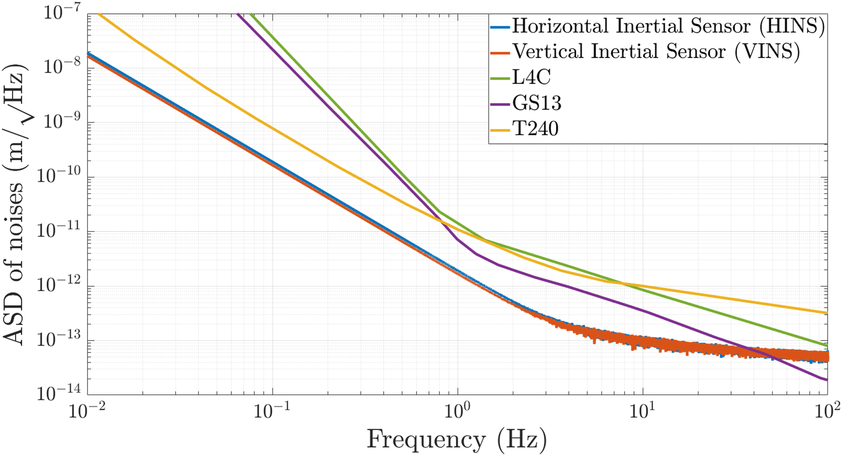
Six-degrees-of-freedom platform
The payload to be isolated is a hexagonal-shaped platform. It is placed on three vertical and three horizontal springs that are mounted on top of a passively isolated rectangular stage (Figure 5). On top of the platform, vacuum chambers are mounted, each one containing a horizontal inertial sensor and a vertical inertial sensor. Two laser sources and two beam splitters alongside optical fibers are used to feed the six inertial sensors with laser beams at 1550 nm wavelength and 5 mW power per sensor. The interferometric readout includes three photodiodes, and their signals are passed through an analog-digital converter and further processed using a demodulation algorithm. This algorithm gives the output of the relative displacement of the inertial sensor in real time.
9
Six voice coil actuators are mounted between the passive stage and the platform to allow actuation on the bottom face of the platform. They are placed in a quasi-collocated manner with the sensors to ensure alternating complex poles and zeros in the transfer functions from actuators to inertial sensors and hence facilitate the control of the system.
10
Experimental setup of the platform (hexagonal-shaped table). Two laser sources feed the inertial sensors using optical fibers and two beam splitters. Each sensor has an interferometric readout that returns the voltage of three photodiodes as an output. Photodiodes signals are passed through an analog-digital converter and demodulated in real time to give the displacement measured by each sensor. These signals are multiplied by a controller matrix and passed through a digital-analog converter to give the control command which is fed to a current amplifier that drives six voice coil actuators (in black boxes). The platform is placed on a passive isolation stage (rectangular table).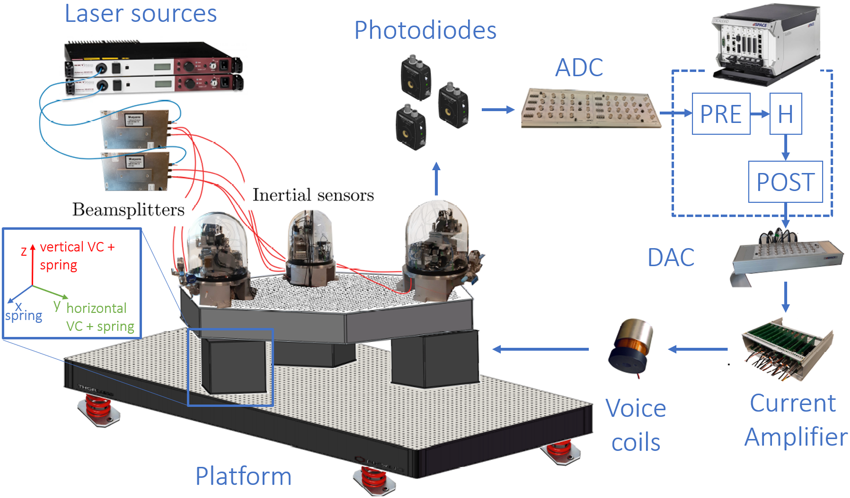
Furthermore, the actuators and springs of the platform are perfectly collocated with each other (both inside the three black boxes shown in Figure 5). The actuator architecture can be shown in the sketch in Figure 6 where every vertical actuator coincides with a horizontal one and the three pairs of horizontal actuator-vertical actuators are placed and oriented in a way that corresponds to a third-order rotational symmetry. Inertial sensors that are placed on top of the active platform are oriented in the same direction as the actuators. Sketch showing actuators’ positions and directions on the active platform. The orientations of the horizontal actuators are 120° shifted from each other to facilitate actuation in X and Y directions. Vertical actuators have the same orientation, allowing them to actuate in Z direction. All six actuators are placed away from the center of mass to allow applying moments around the three axes.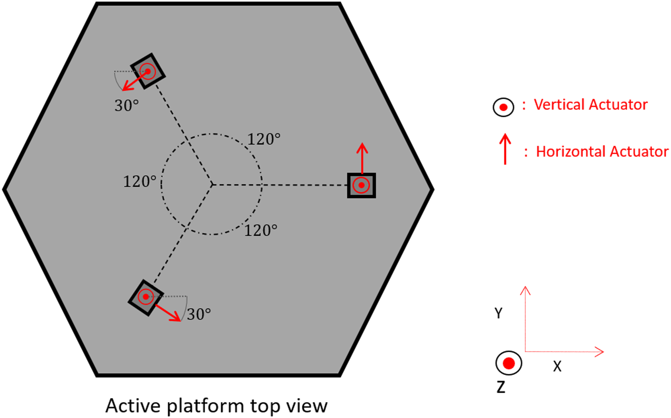
A multibody system model was built using Simscape
TM
.
11
Each sensor is modeled as a one-degree-of-freedom oscillator whose output is the relative displacement between the active platform and its proof mass. The actuators, springs, and damping elements are then defined on the bottom face of the active stage as point elements with stiffness, damping ratios, and defined input force (Figure 7). CAD view of the Simscape
TM
model of the six-degrees-of-freedom platform.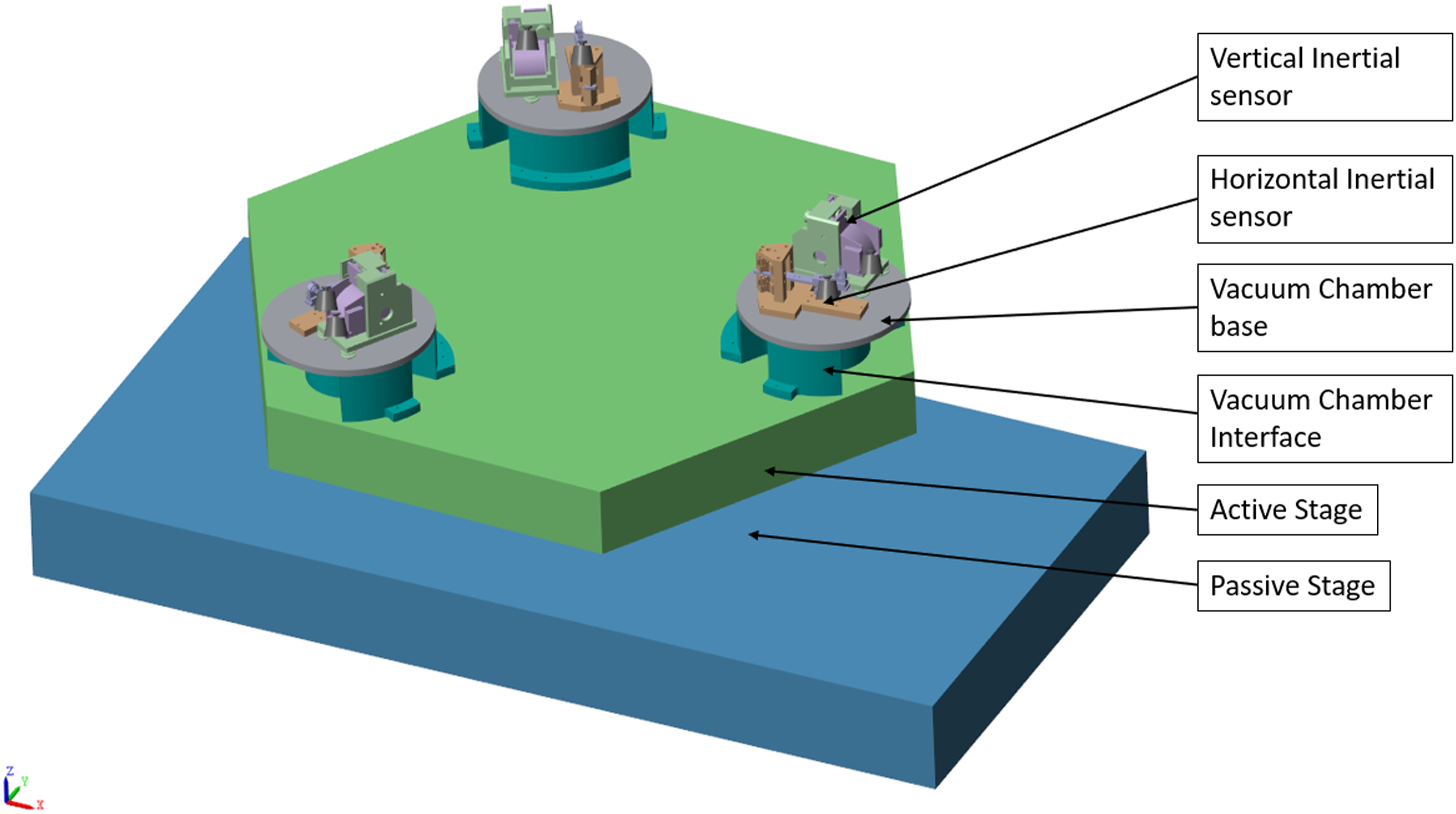
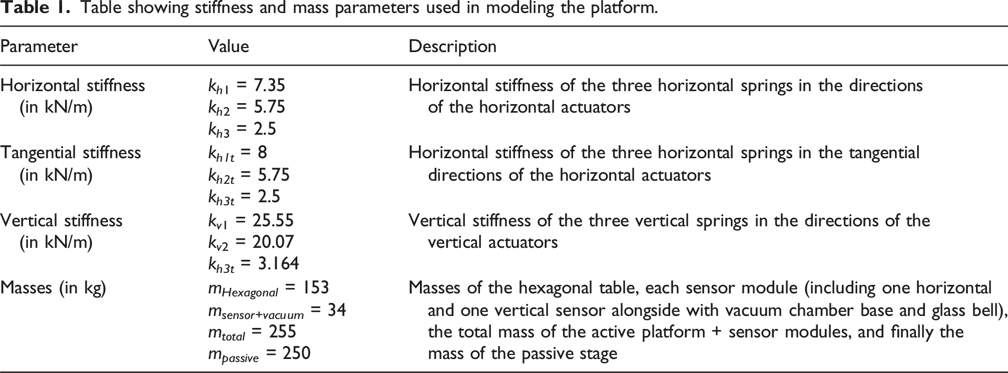
Table showing stiffness and mass parameters used in modeling the platform.
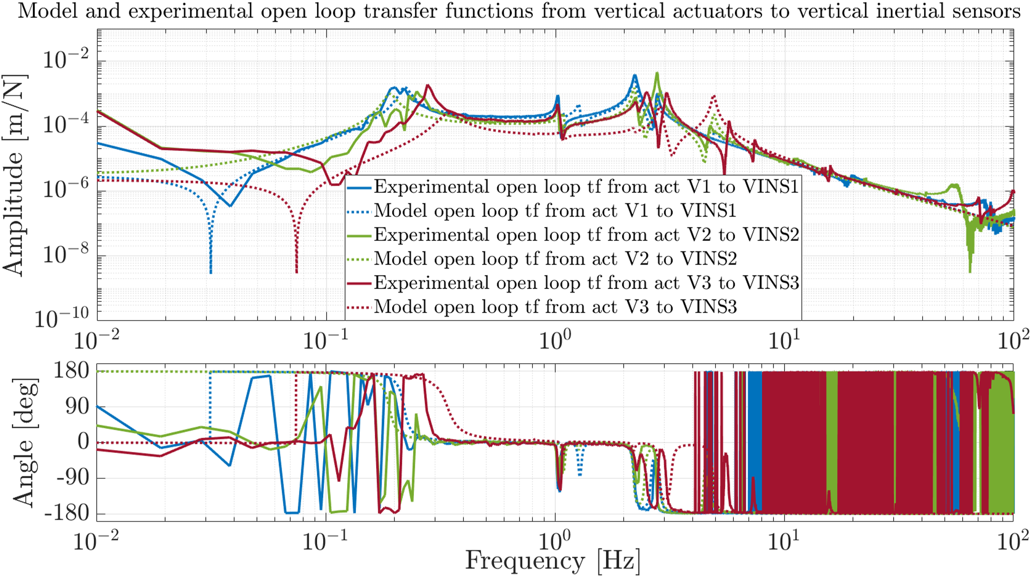
Model-experimental open loop transfer functions from each actuator to its collocated sensor comparison is shown in Figure 8 for horizontal loops and Figure 9 for vertical loops. Resonances of the horizontal and vertical inertial sensors are popping out around 0.2–0.3 Hz followed by the rigid body modes of the active platform between 0.8 and 5 Hz. The model sufficiently matches the experiment from 0.1 Hz above, however, this matching drops at lower frequencies due to the tilt-horizontal coupling problem (check section) where it is not straightforward to anticipate this coupling behavior using multibody system modeling. Bode plots of modeled transfer functions (in dotted lines) and experimental transfer functions (in solid lines) from horizontal actuators to horizontal inertial sensors. Bode plots of modeled transfer functions (in dotted lines) and experimental transfer functions (in solid lines) from vertical actuators to vertical inertial sensors.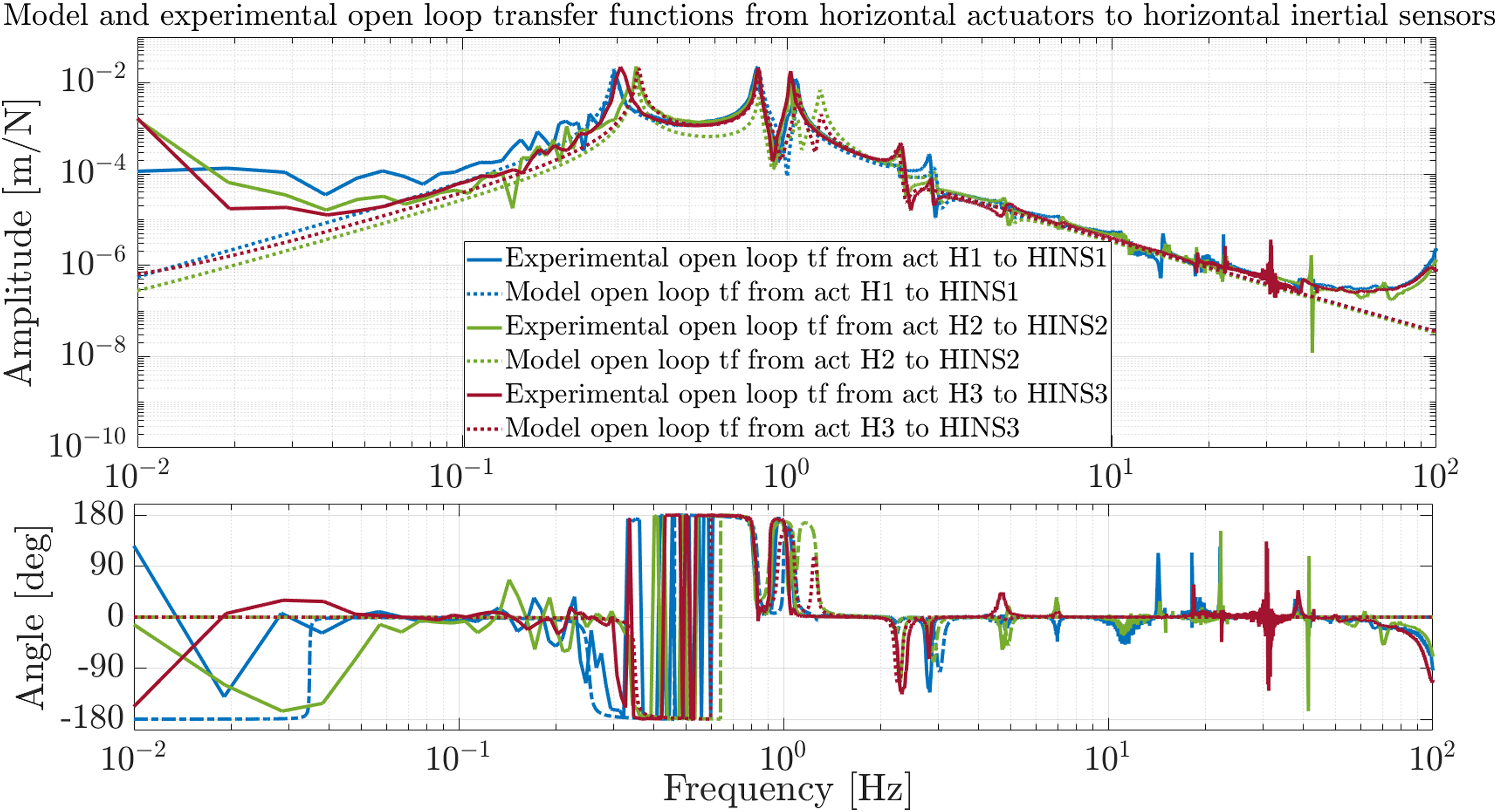
Control approach
A decentralized control approach is considered to actively isolate the platform. The signal from each inertial sensor passes through a controller and is fed back to its quasi-collocated voice coil actuator, as shown in Figure 10. Sketch showing decentralized control architecture for the six-degrees-of-freedom system.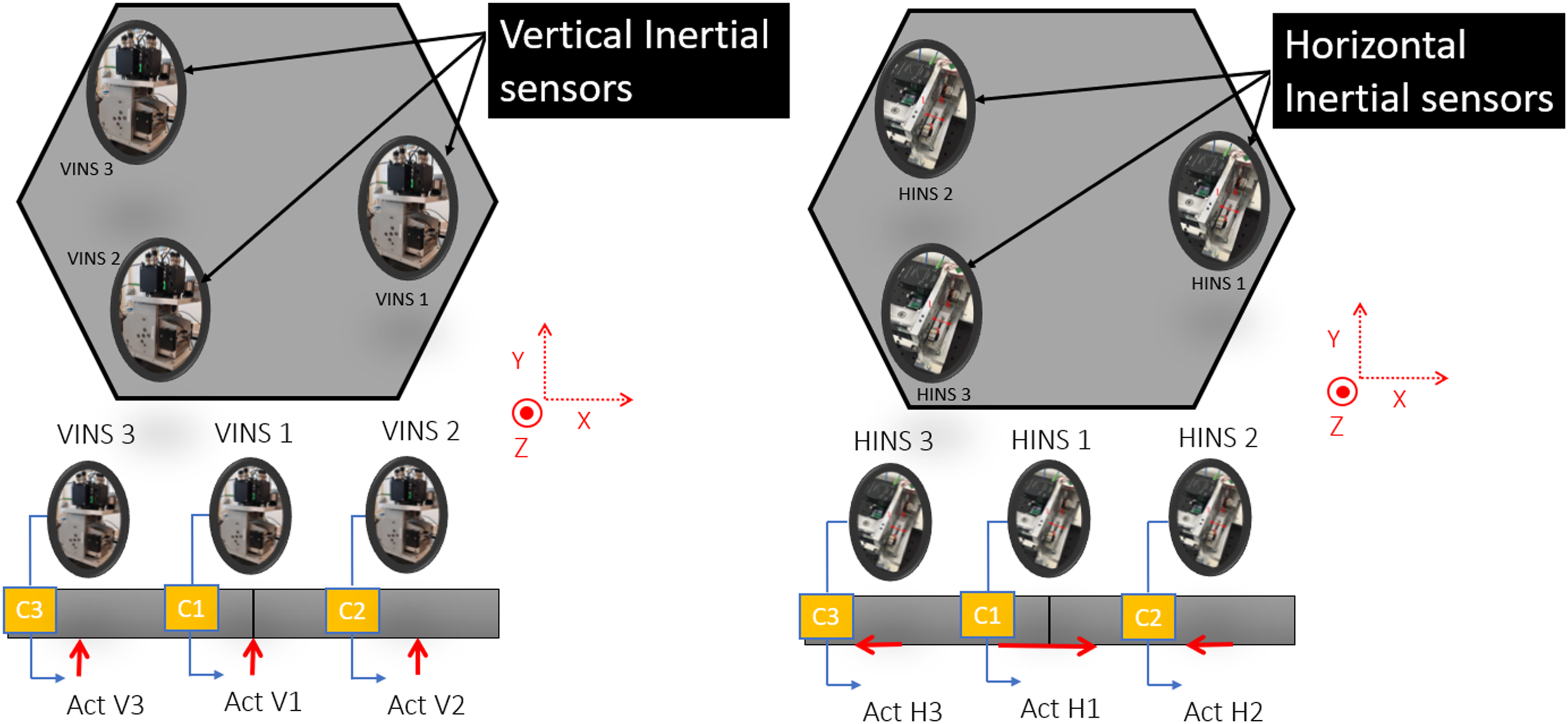
Since the sensor-actuator architecture corresponds to a third-degree rotational symmetry architecture the six diagonal transfer functions can be described using two open loops, the open loop from a horizontal actuator to a collocated horizontal sensor is denoted as a horizontal loop and the open loop from a vertical actuator to a collocated vertical sensor is denoted as a vertical loop. Then, two lead-lag controllers are designed and implemented experimentally to close horizontal and vertical loops as in (7) and (8) respectively:

The Bode plots of these controllers can be shown in Figure 11 multiplied by a first-order high-pass filter with a corner frequency of 50 mHz to avoid actuator saturation and a second-order low-pass filter with a corner frequency of 50 Hz to diminish the impact of flexible modes after 100 Hz. Bode plot of horizontal and vertical controllers used in decentralized sequential loop closing.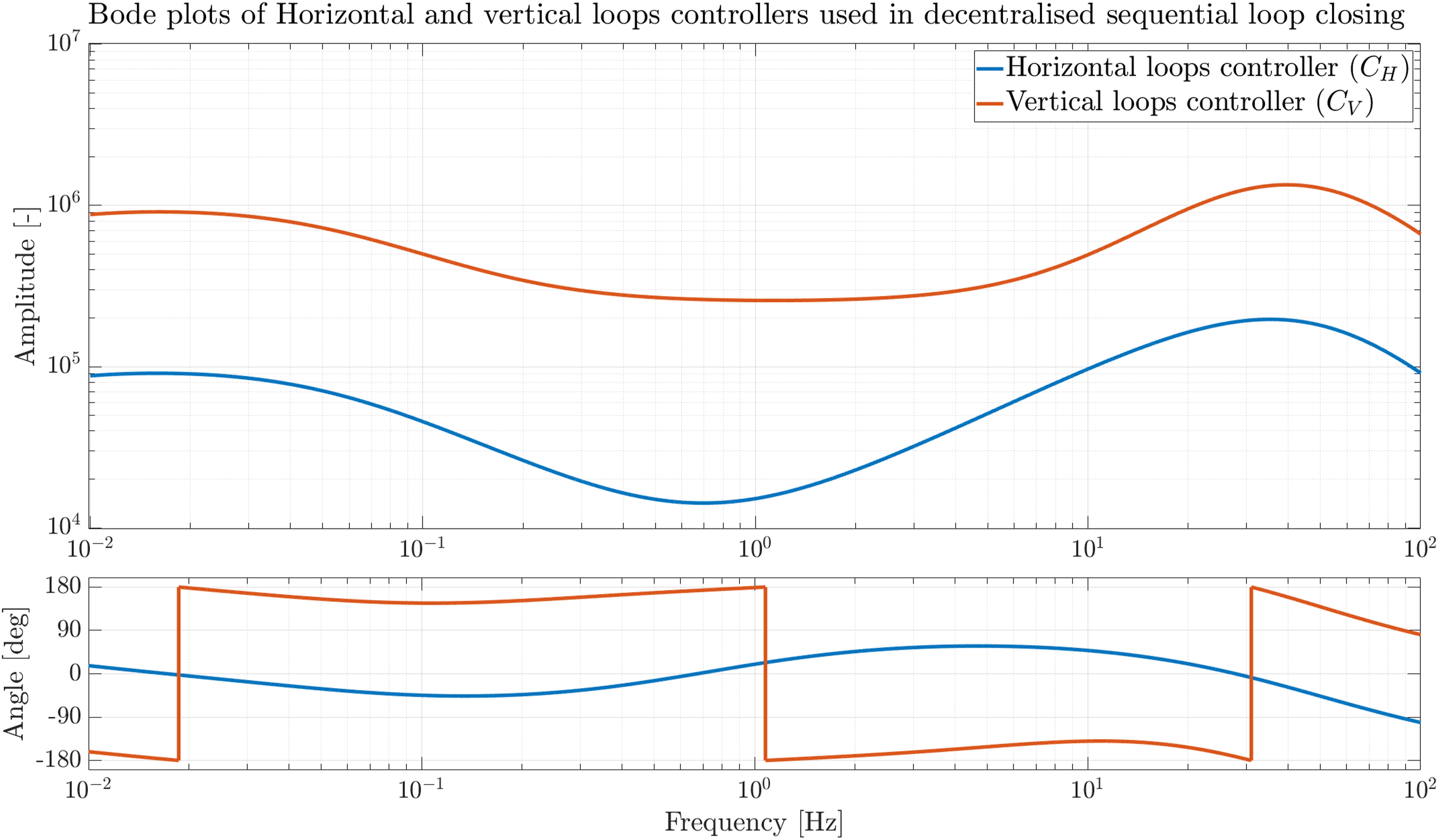
Moreover, since the system is highly coupled, sequential loop closing is used to design controllers while guaranteeing MIMO stability.
12
The coupling in the plant can be visualized using the block diagram in Figure 12. Block diagram showing subsystems and controllers where 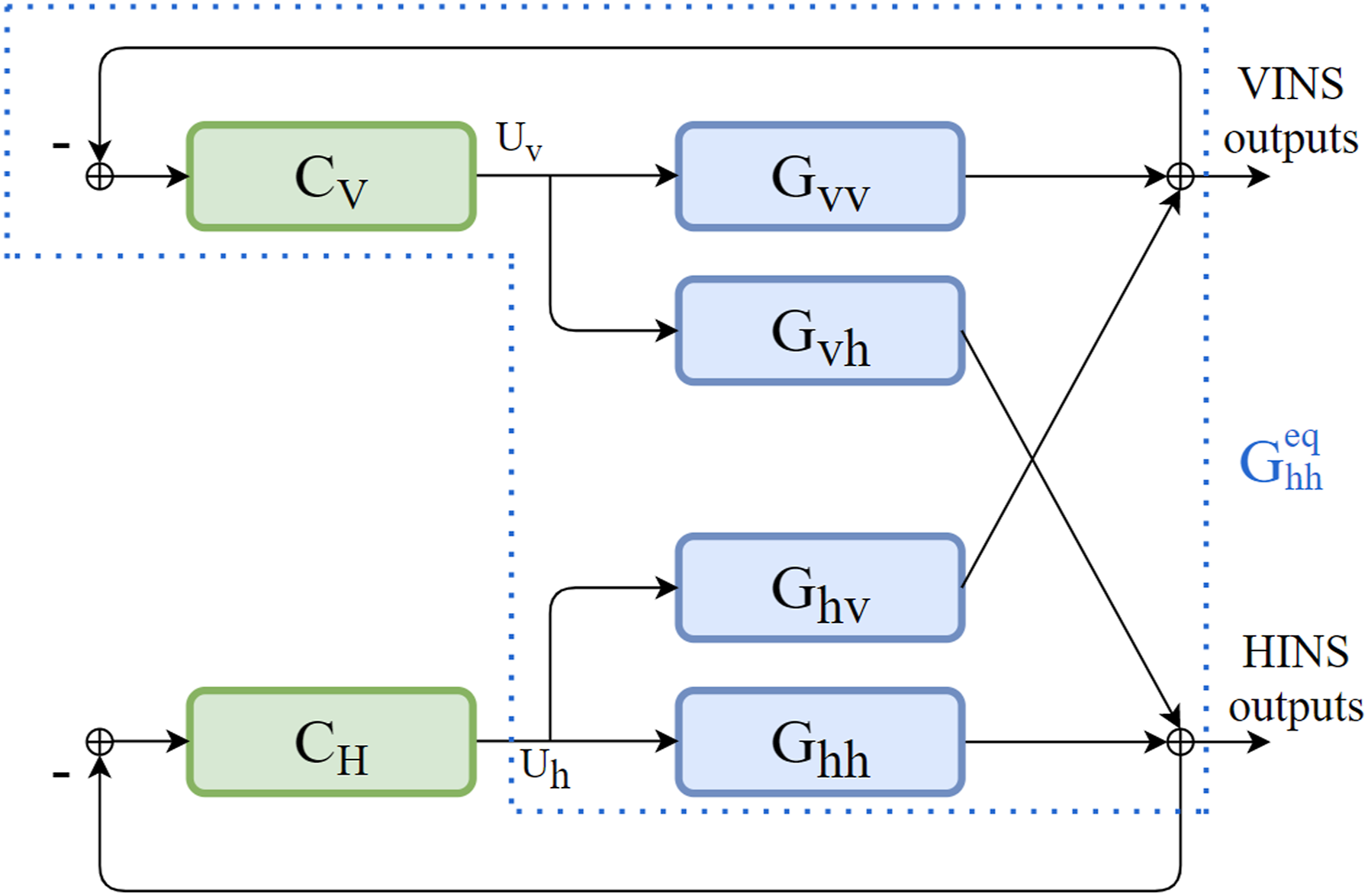
Sequential loop design simplifies MIMO stability by assessing sub-systems’ stability with fewer inputs and outputs. In the case of the platform, stability could be guaranteed by first designing a 3 × 3 controller C
V
while ensuring that it stabilizes G
vv
, this yields an equivalent
Moreover, after applying sequential loop closing for the first time, the system’s stability is dependent on two 3 × 3 MIMO systems. The stability of each of them is then assessed using sequential loop closing again while ensuring identical controllers for the three horizontal loops and the three vertical loops.
Experimental results
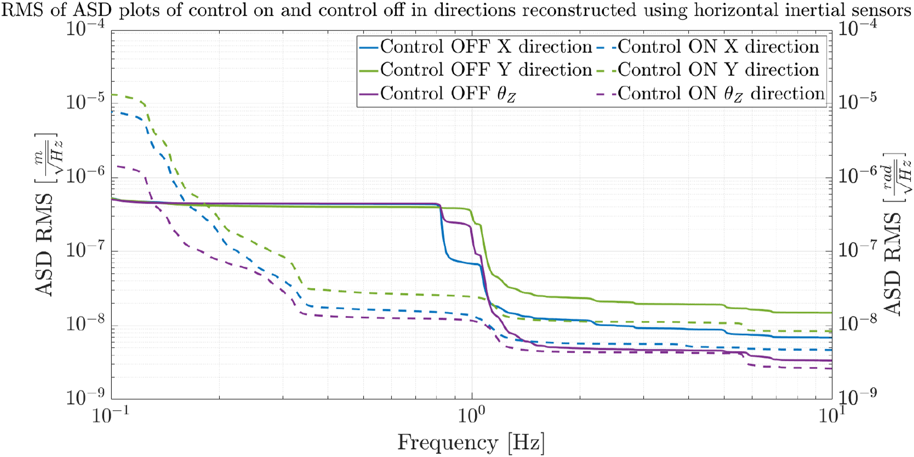
Outputs of the six inertial sensors are multiplied by their inverse dynamics and then by decoupling matrices to reconstruct sensing in Cartesian coordinates at the center of mass of the platform. The amplitude spectral densities for control off and control on between 100 mHz and 10 Hz in X, Y, and θ
Z
directions are shown in Figure 13 (RMS value in Figure 17). Isolation in these three directions comes from closing the loops from horizontal actuators to the corresponding quasi-collocated horizontal inertial sensors. We obtained around half to one order of magnitude of isolation between 300 mHz and 3 Hz. Performance limitations in these degrees of freedom come from the translation-rotation coupling problem of inertial sensors which is more significant in horizontal sensors. Amplitude spectral densities of displacements measured in X, Y, and θ
Z
directions on top of the platform for control off (solid lines) and control on (dashed lines).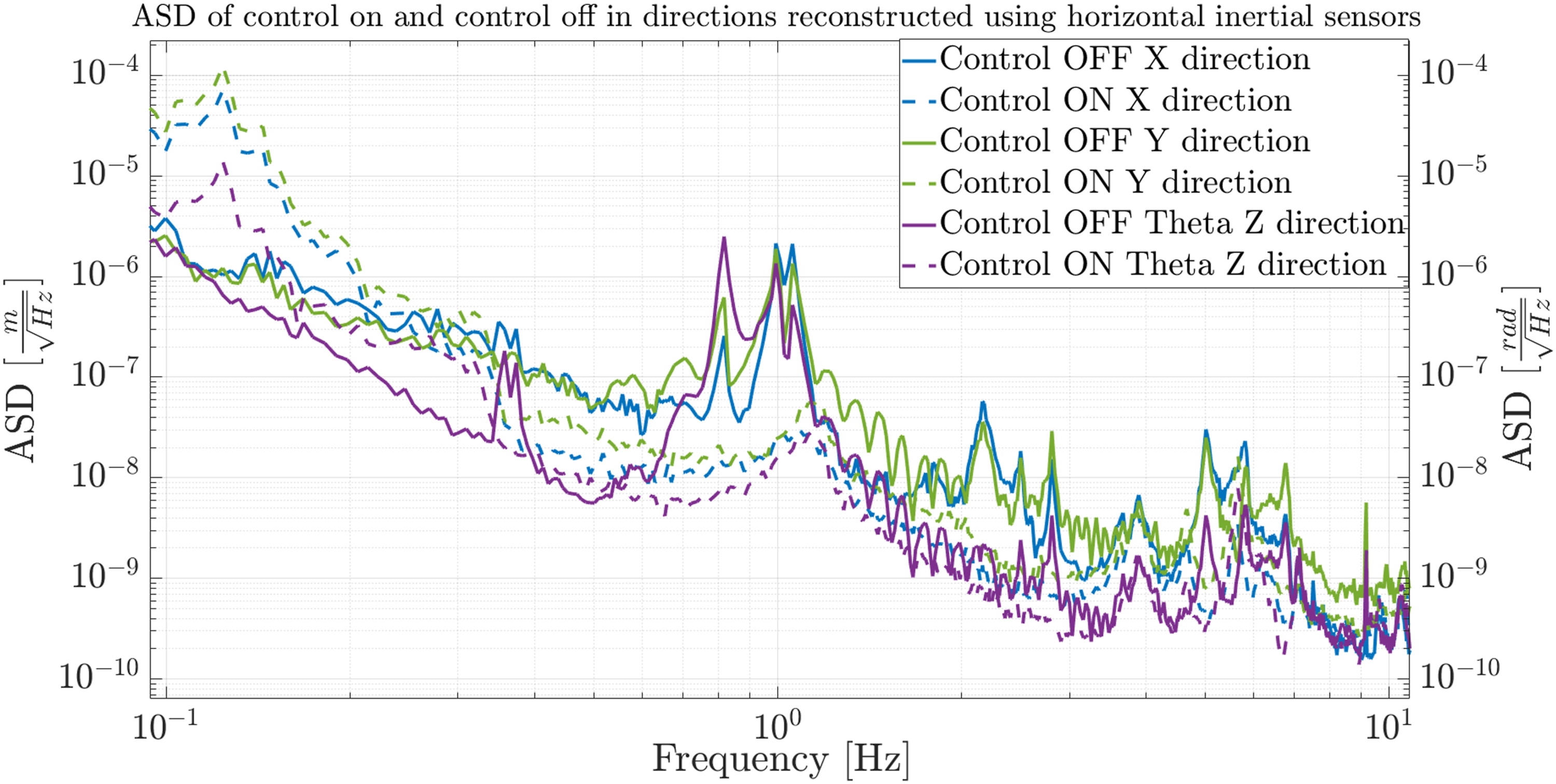
Moreover, the translation-rotation coupling is less critical for vertical inertial sensors allowing to apply more gains when closing loops from vertical actuators to corresponding collocated vertical inertial sensors. This allows more isolation in the remaining degrees of freedom Z, Theta
X
and Theta
Y
. In these three directions, the platform is actively isolated between 100 mHz and 10 Hz up to two orders of magnitude, as shown in Figure 14 (RMS value in Figure 16). Amplitude spectral densities of displacements measured in Z, θ
X
, and θ
Y
directions on top of the platform for control off (solid lines) and control on (dashed lines).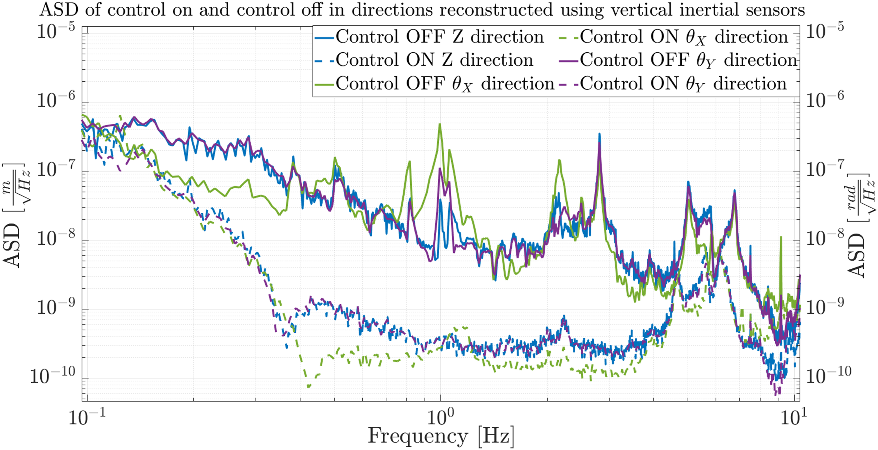
By placing a Guralp 6T seismometer on the ground, it was possible to check the transmissibility transfer functions from the ground displacement in the three translational directions to the platform displacement in the three translational directions. They can be shown in Figure 15. The order of isolation shown in the transmissibilities is similar to what is shown for the ASDs in X, Y, and Z translational directions, consolidating the obtained isolation level. Figure showing the magnitude of the ground to active platform transmissibility transfer function for control off (solid lines) and control on (dotted lines) in X (in blue), Y(in dark green), and Z (in purple) directions.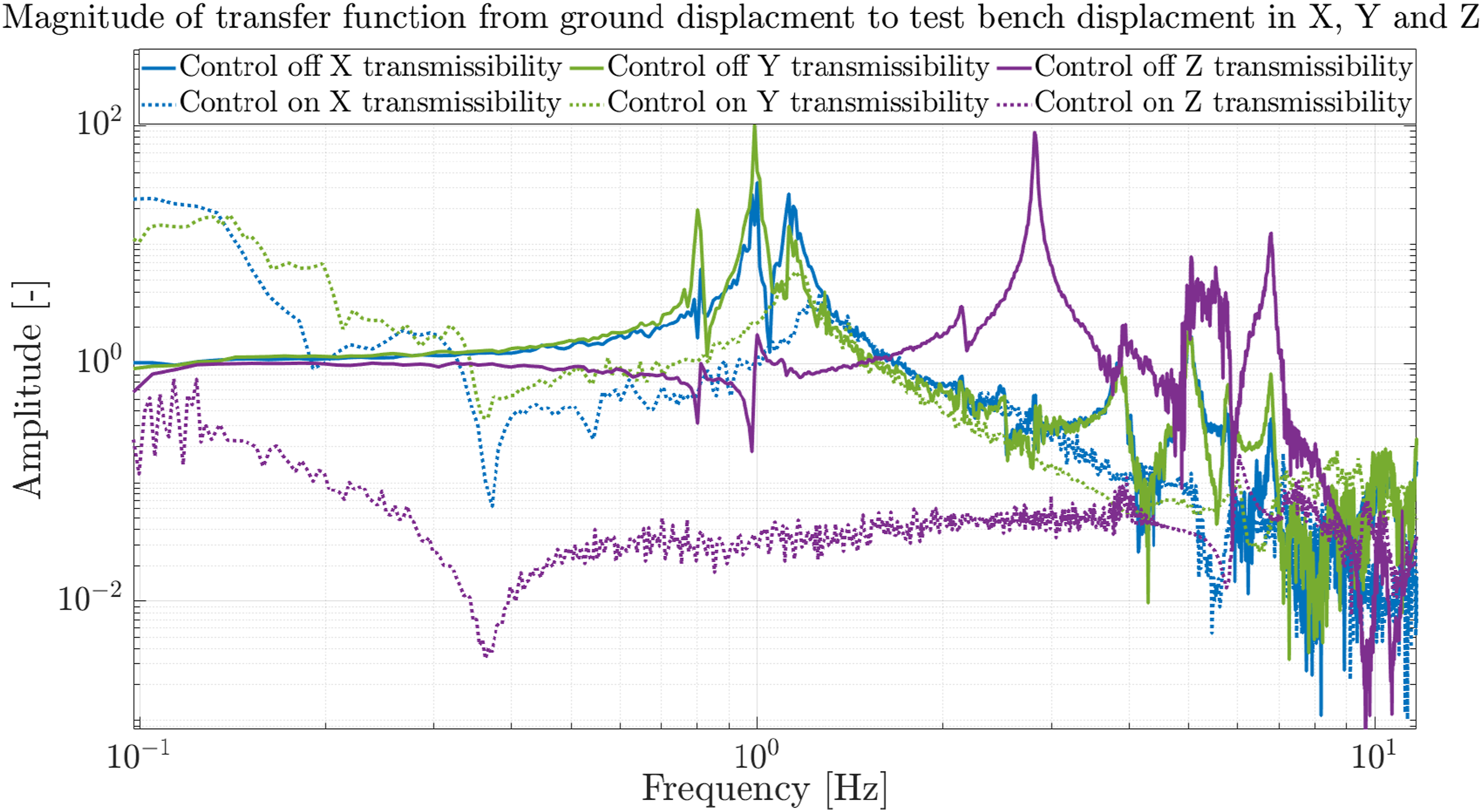
Practical limitations
Some practical limitations of the isolation level of the platform are: • • • •
Conclusion
This paper presented a six-degree-of-freedom platform dedicated to low-frequency seismic isolation of instruments requiring high precision. To the best of the author’s knowledge, this is the first platform fully controlled by interferometric inertial sensors. The platform was actively isolated in the vertical direction (Z) and rotational directions around the two horizontal axes (θ X , θ Y ) between half and two orders of magnitude for frequencies between 100 mHz and 10 Hz. However, this isolation dropped down in the two horizontal directions (X, Y) and rotational direction around the vertical axis (θ Z ) where it was isolated by half an order of magnitude between 300 mHz and 3 Hz.
Footnotes
Acknowledgments
The authors gratefully acknowledge the European Research Council, Consolidator grant SILENT (grant agreement number 866259) for funding this research and the French Community as part of the financing of a FRIA grant for Jennifer Watchi (grant number: FC 27289). The authors also acknowledge the LIGO scientific community for reviewing this research. This paper has been assigned the LIGO DCC number LIGO-P2400052.
Funding
The author(s) disclosed receipt of the following financial support for the research, authorship, and/or publication of this article: H2020 European Research Council (866259).
Declaration of conflicting interests
The author(s) declared no potential conflicts of interest with respect to the research, authorship, and/or publication of this article.
Appendix
Cumulative RMS of amplitude spectral densities of displacements measured in Z, θ
X
, and θ
Y
directions on top of the platform for control off (solid lines) and control on (dashed lines).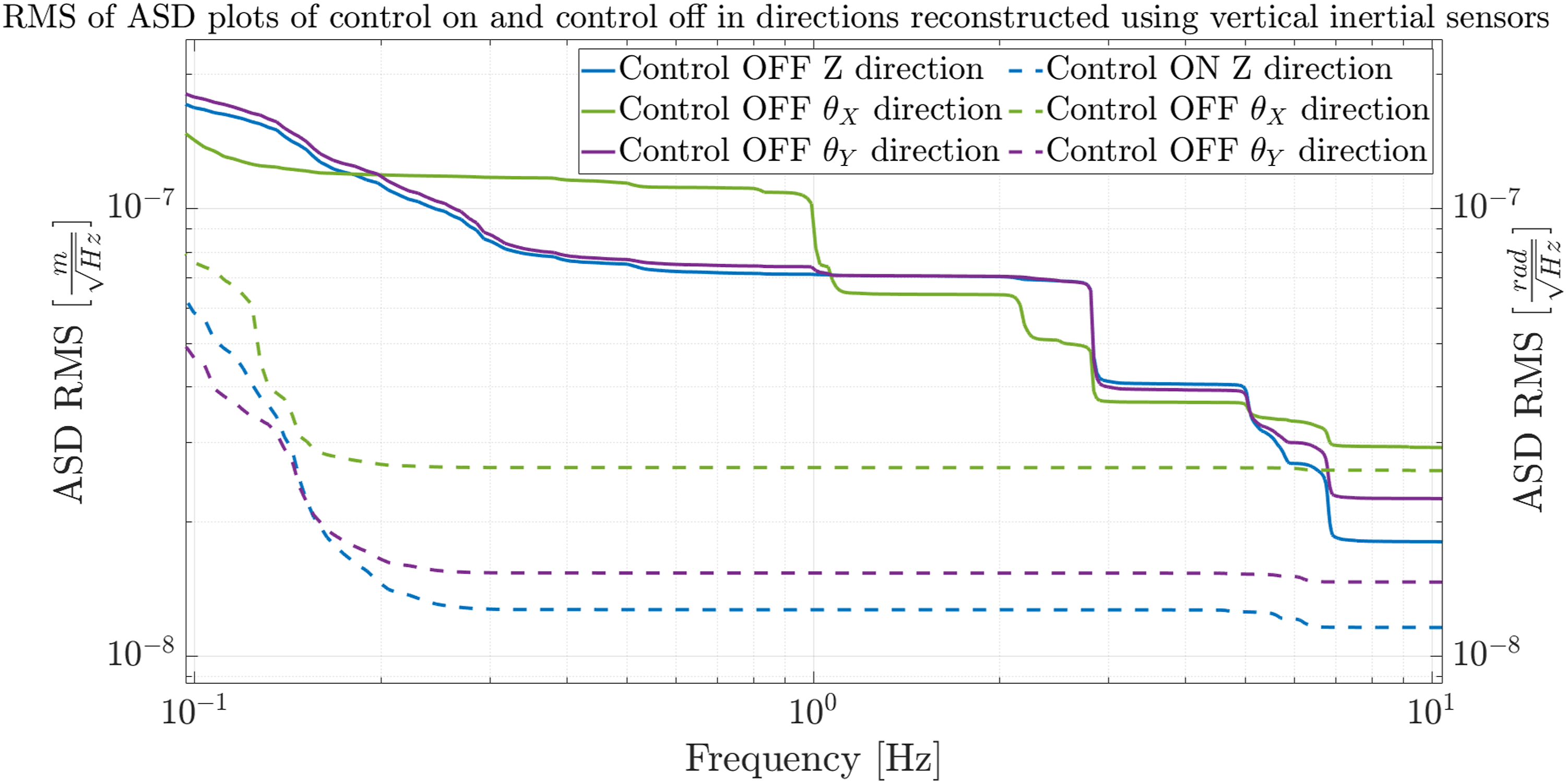
Cumulative RMS of amplitude spectral densities of displacements measured in X, Y, and θ
Z
directions on top of the platform for control off (solid lines) and control on (dashed lines).