
Abstract
Under the influence of road excitations, the acquisition of optimal time-delayed feedback control parameters is deemed crucial for the improvement of the vibration reduction effect of semi-active vehicle suspension systems. Moreover, different effects on vibration reduction are generally exhibited by vehicle suspension systems based on different time-delayed state feedback control. Therefore, the mechanical model of time-delayed feedback control in semi-active vehicle suspension systems is chosen as the research focus in this paper. Firstly, the optimal values of time-delayed feedback control parameters are derived through an optimization algorithm based on “equivalent harmonic excitation.” Secondly, driven by the optimal values derived from optimization, this study is primarily focused on the investigation of the vibration reduction effect of time delay in a vehicle’s semi-active suspension system under road excitation, thereby revealing the optimal time-delayed feedback control strategy. Finally, the study suggests that a stable state with full time delay within the effective vibration frequency range is more likely to be achieved by the semi-active vehicle suspension system based on time-delayed state feedback control of wheel vertical displacement. Additionally, the optimization efficiencies for vertical seat acceleration, vertical body acceleration, suspension travel, and tire displacement are reported as 97.73%, 98.95%, 47.30%, and 46.38%, respectively.
Keywords
Introduction
The suspension system stands as a crucial constituent of a vehicle, exerting a significant impact on aspects such as smooth ride quality, passenger comfort, and handling stability. In contrast to conventional passive suspensions, semi-active suspensions demonstrate promising applications owing to their advantages in terms of a straightforward structure, cost-effectiveness, high reliability, and control efficacy approaching that of active suspensions.1–3 However, they are not without challenges, including substantial energy consumption and issues related to time delays in the control system.4–6 Nonetheless, during active/semi-active control procedures, time delays persist due to factors such as signal acquisition, transmission, control computations, and actuator delays. Research underscores that overlooking these delays during the design phase can diminish the control system’s performance and may even lead to system instability.7–9 However, as scholars in the field delve deeper into the study of time delays, they consistently unearth the positive aspects of appropriate delays—expanding the effective vibration damping frequency band, enhancing the control effectiveness of the system, and even improving the stability of the system.10,11
From the perspective of harnessing time delays, Olgac et al. 12 introduced the concept of “time-delayed linear dynamic absorbers.” These absorbers can dynamically fine-tune the feedback gain coefficient and time delay in real-time through an analysis of the external excitation frequency. This capability enables the control of vibrations within the primary system. Subsequent extensive research literature by Olgac and their team13–20 further demonstrates that real-time adjustments to the absorber’s feedback gain coefficient and time delay, based on an analysis of external excitation frequencies, effectively manage vibrations in the primary system. This approach yields notable advantages in mitigating vibration.
Given the unique frequency response characteristics of time-delay dynamic absorbers, which can effectively suppress vibrations at specific frequencies while maintaining excellent dynamic performance across a broad frequency range and demonstrating superior energy dissipation capabilities to significantly reduce the dynamic response of structures, research on active/semi-active suspension systems that consider time delays has emerged as a focal point for many scholars in recent years, leading to significant advancements in the field.
Fu et al. 21 centered their study on a quarter-vehicle suspension with time delays, dissecting the progressive stability mechanisms of the semi-active suspension control system through the utilization of delayed sky-hook switching control. Song et al. 22 delved into active vehicle suspensions with control delays, employing a stochastic preview control strategy. They emphasized that overlooking the impact of delays could lead to instability in the suspension system. Ji et al. 23 scrutinized active vehicle suspension systems considering time delays, utilizing a combined theoretical and experimental approach to assess the influence of delays on suspension system vibration characteristics. Their analysis included examining the relationship between delay and spring-loaded acceleration root mean square values under varying gain conditions. Yan 24 focused on a 2-degree-of-freedom quarter-vehicle semi-active suspension model based on vehicle speed delay state feedback control. They optimized structural parameters and control gains using a genetic algorithm, revealing a 22.7% reduction in the optimized vertical acceleration vibration amplitude compared to the pre-optimized state. This underscored the effectiveness of the speed-delay feedback control strategy in enhancing suspension system performance. Qu et al. 25 crafted a dynamic model for a half-vehicle semi-active suspension system based on wheel vertical displacement delay state feedback control. Leveraging the particle swarm optimization algorithm, they obtained feedback gain coefficients and delays, resulting in a 15.10% and 22.48% reduction in the root mean square values of vertical and pitch accelerations, respectively, compared to a passive suspension system under random road excitations. Yan et al. 26 scrutinized the damping performance of a quarter-vehicle suspension system under optimal delayed feedback control and discussed the impact of delays on the control stability of active suspension systems. Liu et al. 27 formulated a quarter-vehicle suspension model based on delayed state feedback control of vertical acceleration. With the minimum vertical acceleration amplitude as the optimization objective, the results demonstrated a reduction of at least 19.60% in the vibration amplitude of the optimized vertical acceleration under harmonic road excitations compared to the pre-optimized state.
In conclusion, exploring the potential of leveraging time delays, it is entirely viable to expand the effective vibration damping frequency range of a vehicle’s semi-active suspension system and improve the delay damping effect under road excitations by introducing well-suited active delays. This can be achieved through the fine-tuning of the interplay between feedback gain coefficients and delays. However, the predominant findings from current research on the delay damping control effectiveness of semi-active suspension systems suggest that: 1. Historically, the damping performance of vehicle semi-active suspension systems has shown relative effectiveness under simple road harmonic excitations. However, the damping effectiveness under random road excitations with delays is generally subpar. Furthermore, there is a prevalent issue of conflicting performance indicators within various evaluation metrics for vehicle suspension systems. Therefore, further exploration is needed to effectively enhance the overall vibration damping performance of vehicle suspension systems and optimize designs to address the conflicting performance indicators across various evaluation metrics. 2. Previous research on time-delayed damping control in vehicle semi-active suspension systems has indicated that different time-delayed feedback control strategies typically yield varying time-delayed damping control effects. Therefore, further exploration and research are necessary to identify the optimal time-delayed feedback control strategy.
Based on the aforementioned research analysis, this paper endeavors to enhance the vehicle’s semi-active suspension system through the optimized design of delay feedback control parameters. The primary emphasis is placed on analyzing how these parameters influence both the damping effectiveness and stability of the system. Subsequently, through numerical simulation analysis, the paper will delve into a comprehensive exploration of the vibration damping performance of a vehicle’s semi-active suspension system. The focus will be on different delay state feedback control strategies under the influence of random road excitations. This investigation aims to discern the comparative strengths and weaknesses of various delay damping control effects.
Mechanical model of time-delayed vibration reduction control in semi-active suspension systems for vehicles
To streamline the research focus, the modeling process excludes considerations of imbalance forces stemming from vehicle factors like the engine and transmission affecting the vertical vibration of the car body. The primary emphasis is placed on investigating the vertical vibration caused by road irregularities. Furthermore, the model disregards the pitch and roll motions of the vehicle.
The vibration control model of the quarter-car semi-active suspension system, which incorporates time-delayed state feedback control and has three degrees of freedom, is illustrated in Figure 1. In this system, the suspension response is regulated by adjusting the damping characteristics of components such as time-delayed dampers. However, it does not actively generate or apply external forces. Consequently, the system functions as a semi-active suspension system for the vehicle. As depicted in Figure 1, the simplified physical model of the 1/4 vehicle suspension system comprises three essential degrees of freedom: vertical oscillation of the seat, vertical movement of the vehicle body, and vertical motion of the wheel. Within this model, m
s
, m
b
, and mw denote the masses of the passenger seat, sprung mass, and unsprung mass, respectively. The damping coefficients for the seat suspension, vehicle suspension, and tire are represented by c
s
, c
b
, and c
t
. Additionally, k
s
, k
b
, and k
t
signify the stiffness of the seat suspension, vehicle suspension, and tire. The displacements of the passenger seat, sprung mass, and unsprung mass are denoted by x
s
, x
b
, and x
w
, while x
q
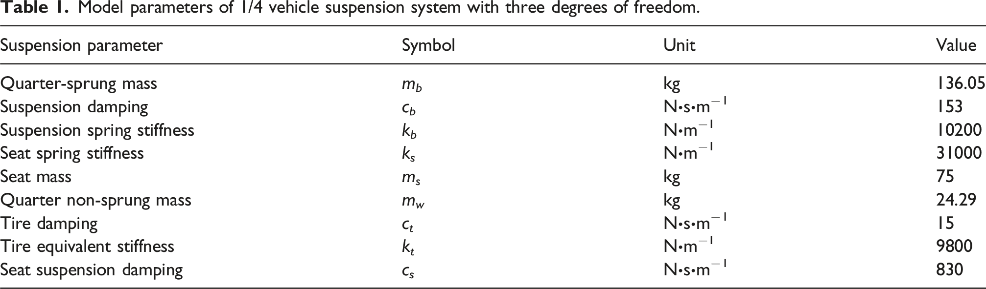
indicates the input displacement from the road. Further details regarding the parameter values for the three degrees of freedom in the 1/4 vehicle suspension system can be found in Table 1. Mechanical model of three degree of freedom 1/4 vehicle semi-active suspension system. Model parameters of 1/4 vehicle suspension system with three degrees of freedom.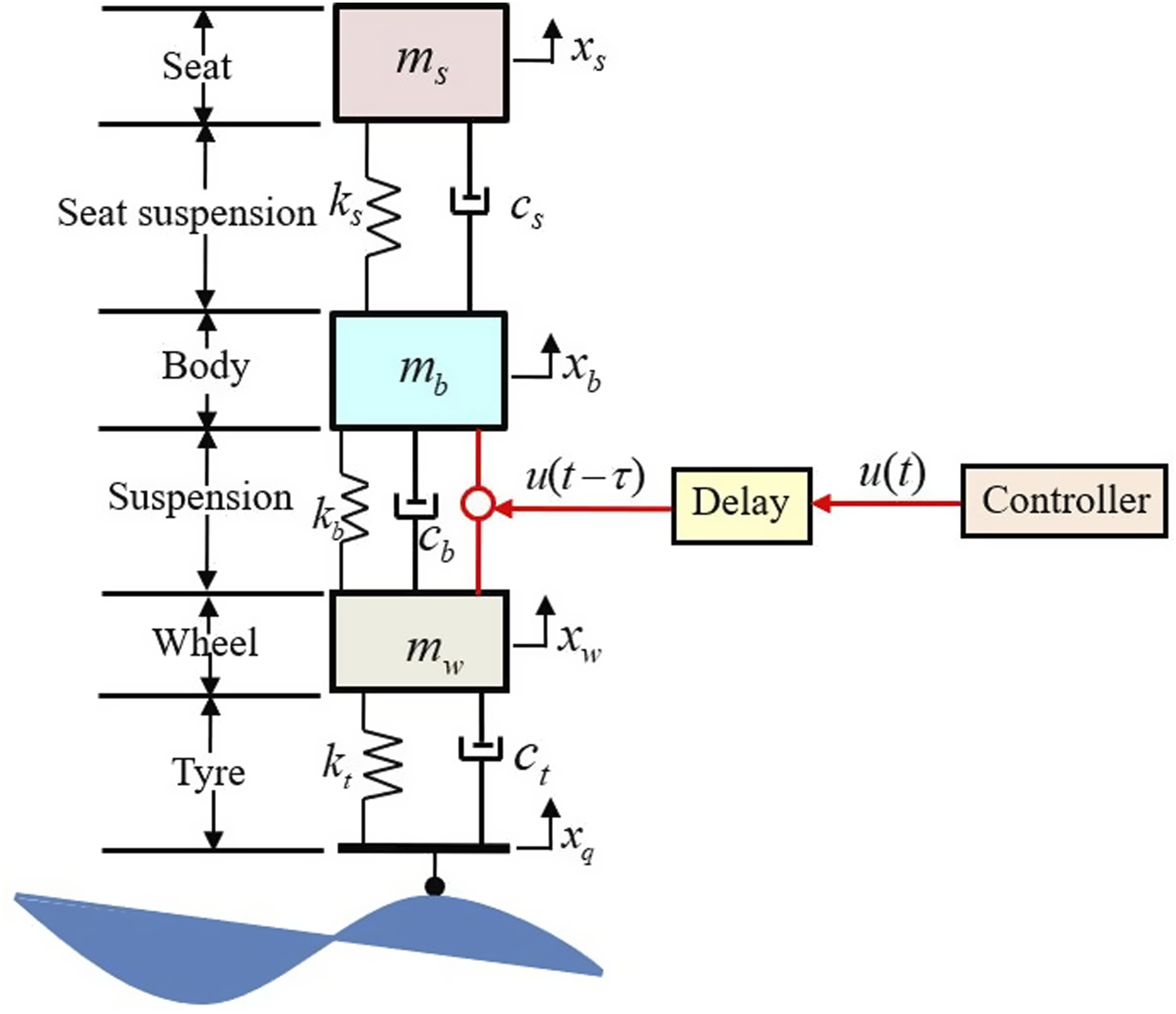
As illustrated in Figure 1, the term “u(t–τ)” in the model signifies the incorporation of time-delayed feedback control force into the vehicle suspension system. In this context: (1) When “u(t–τ) ≠ 0,” it indicates the transformation of a passively controlled vehicle suspension system into a vehicle semi-active suspension system based on time-delayed state feedback control. (2) When “u(t–τ) = 0,” it denotes the conversion of a vehicle semi-active suspension system based on time-delayed state feedback control into a passively controlled vehicle suspension system.
In accordance with the physical model of the vehicle semi-active suspension system with time-delayed feedback control as depicted in Figure 1, the coordinate origin is now chosen at the equilibrium positions of the seat, vehicle body, and wheel. Using Newton’s second law, we derive the motion differential equations for the 1/4 vehicle semi-active suspension system based on time-delayed state feedback control.
Vertical motion equation for the seat
Vertical motion equation for the vehicle body
Vertical motion equation for the wheel
If equations (1)–(3) are non-dimensionalized,
28
the following results can be obtained


Here, if a time-delayed state feedback control strategy based on the vertical displacement of the wheel is employed, the time-domain expression for the time-delayed state feedback control force 
Similarly, if a time-delayed state feedback control strategy based on the vertical displacement of the vehicle body is utilized, the time-domain expression for the time-delayed state feedback control force 
Now, to streamline the motion differential equations for the 1/4 vehicle semi-active suspension system based on distinct time-delayed state feedback control strategies, we represent them in a matrix form, identified as

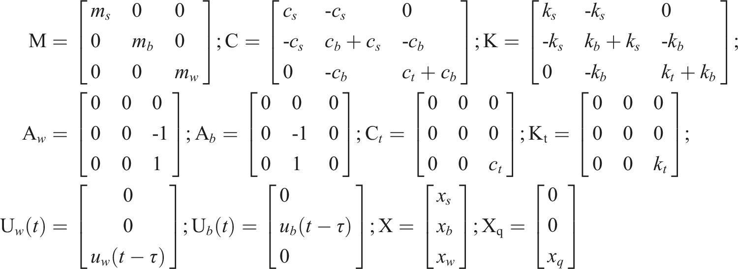
where M — Matrix representing the masses of various vehicle components. C — Matrix denoting the damping characteristics of the system. K — Matrix expressing the stiffness of the system. Kt — Matrix indicating the stiffness of the tires. Ct — Matrix representing the damping of the tires. X — Matrix encompassing the vertical displacements of different vehicle components. Xq — Matrix representing the unevenness of road surface.
Assuming the eigenvalues of equations (9) and (10) are denoted as s, Laplace transformation yields

Substituting these into equations (11) and (12), respectively, we obtain

In equations (13) and (14), P
w
(s) and P
b
(s), respectively, denote the matrices of time-delayed feedback control forces based on the vertical displacements of the wheel and the vehicle body. Specifically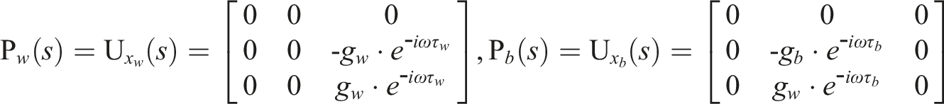
Optimization of time-delayed feedback control parameters in semi-active suspension systems for vehicles
To further enhance the overall vibration damping performance of the vehicle suspension system and optimize the parameters of its time-delayed state feedback control, an attempt is made to use the minimum non-dimensionalized amplitude-frequency characteristic function of the vertical acceleration of the vehicle body within an effective vibration frequency band as the objective function for optimization.
29
Additionally, in the optimization process of the time-delayed feedback control parameters of the semi-active suspension system, the minimum vibration amplitude of the vertical acceleration of the vehicle body within the effective frequency range is considered optimal. This is to maximize the satisfaction of the smoothness requirements during vehicle operation. Therefore, the objective functions can be defined as follows

In this context, consider the constraint conditions for the time-delayed state feedback control parameters based on the vertical displacement of the wheel (g
w
,τ
w
) and the time-delayed state feedback control parameters based on the vertical displacement of the vehicle body (g
b
,τ
b
) as follows

1. The time-domain model of random road excitation generated based on the harmonic superposition method30–32 is selected, and the time-domain model of random road excitation is shown as equation (19)
In the above equation, x q (t) represents the time-domain random displacement of the road surface, Δf is the interval of time frequency, G q (fmid−j) is the road surface roughness coefficient, fmid−j is the center frequency of the interval, θ j represents a random phase angle uniformly distributed in the range (0, 2π), and t represents the travel time.
1) Assuming the vehicle operates on Class C pavement, the pavement roughness coefficient is given by G
q
(f) = 256
2) A vehicle traveling at a speed of v = 60 km/h on a Class C road surface can be analyzed using the relationship between time frequency and spatial frequency, expressed as f = v⋅n. In this context, the effective spatial frequency limits (n1, n2) for the power spectral density of road surface roughness are determined as follows: the lower limit is n1 = 0.015 m−1, and the upper limit is n2 = 0.9 m−1. To calculate the power spectral density and prevent frequency aliasing, we define the sampling interval as Δl. According to the sampling theorem, we have Δl ≤ 0.5⋅v⋅f2−1 = 0.5556 m−1. Based on this constraint, we choose Δl = 0.015 m−1. Consequently, the effective spatial frequency range (n1, n2) can be divided into k = 59 intervals. The center frequency of each spatial sub-interval is given by n mid−j = 0.015⋅j + 0.0075, j=(1,2,…,59). Thus, the center frequency for each time frequency interval is f mid−j = v⋅n mid−j = 0.25⋅j + 0.125, j=(1,2,…,59).
3) If the number of sampling points is N, the length of the simulated pavement roughness should be L = N⋅Δl, where Δl represents the spatial interval between sampling points. The resolution of the sampling spatial frequency is given by Δn = L−1. To ensure the validity of the lower frequency limit n
min
, it is necessary that Δn ≤ nmin. Consequently, we have L ≥ nmin−1 = v⋅f1−1, where v is the vehicle speed and f1 represents the fundamental frequency. This ensures that the simulated pavement roughness effectively captures the relevant frequency characteristics. Therefore, the length of the pavement roughness L must satisfy the inequality: L
min
2. The frequency range is divided into multiple small intervals, and an optimization strategy for the entire interval based on the harmonic excitation at the center frequencies f
mid-j
= 0.25⋅j + 0.125, where j=(1,2,3,…,59), is constructed using equations (15) and (16) with the vertical acceleration of the vehicle body as the fitness function for a particle swarm optimization algorithm. • Firstly, to further enhance the vibration bandwidth and damping effect of the semi-active suspension system under the influence of random road excitation, we consider an analytical expression in the frequency domain for the vertical displacement response of the road input to the vertical acceleration of the body, denoted as • Secondly, concerning the optimization of time-delayed state feedback control parameters for the semi-active suspension system, a time-domain model is utilized based on the harmonic superposition method to generate random road excitation. The vehicle is assumed to travel over a Class C road surface at a speed of v = 60 km/h. To address the constraints on the time-delayed feedback control parameters as indicated in equations (17) and (18), an equivalent harmonic excitation method is employed to formulate a particle swarm optimization algorithm for equations (15) and (16). These equations use J(g
w
, τ
w
) and J(g
b
, τ
b
) as fitness functions. • Finally, to further enhance the vibration bandwidth and damping effectiveness of the semi-active suspension system employing time-delayed state feedback control based on wheel and body vertical displacements under random road excitation, the frequency domain expression for the vertical body acceleration with respect to road input vertical displacement
3. Generally, the Particle Swarm Optimization (PSO) algorithm is primarily used for single-objective optimization but can also be adapted to multi-objective problems. Due to its relatively fast computational performance, it is particularly well-suited for single-objective tasks. Therefore, the time-delayed feedback control parameter optimization strategy, which combines “road surface equivalent harmonic excitation” with “Particle Swarm Optimization,” is implemented using the PSO algorithm, with 200 randomly initialized particles employed for iterative optimization. This process is utilized to independently optimize and determine the optimal values for time-delayed feedback control parameters within the effective vibration frequency range for a semi-active suspension system based on wheel vertical displacement and vehicle body vertical displacement. Specifically, the optimal values are denoted as “(g
wop
,τ
wop
)=(g
bop
,τ
bop
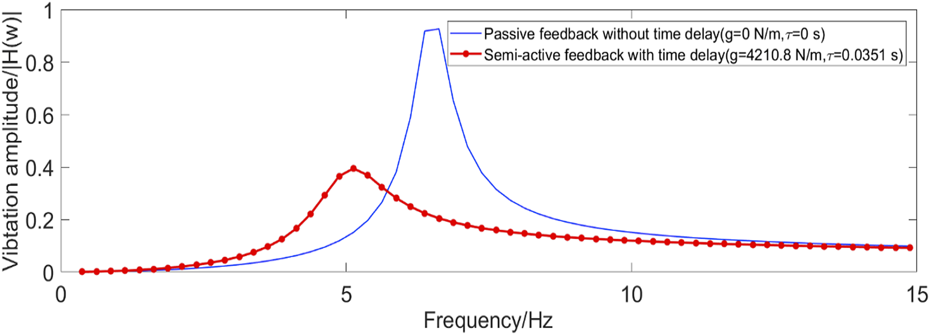
)=(4210.8 N/m, 0.0351 s).” Furthermore, under the same conditions of time-delayed feedback control parameters, the amplitude-frequency characteristic curves of the vehicle body’s vertical acceleration in the effective vibration frequency range are depicted for the semi-active suspension system controlled using different time-delayed state feedback control strategies. These curves are illustrated in Figures 2 and 3. Amplitude-frequency characteristic curve of vertical acceleration of vehicle body based on time-delayed state feedback control of wheel vertical displacement. Amplitude-frequency characteristic curve of vertical acceleration of vehicle body based on time-delayed state feedback control of vertical displacement of vehicle body.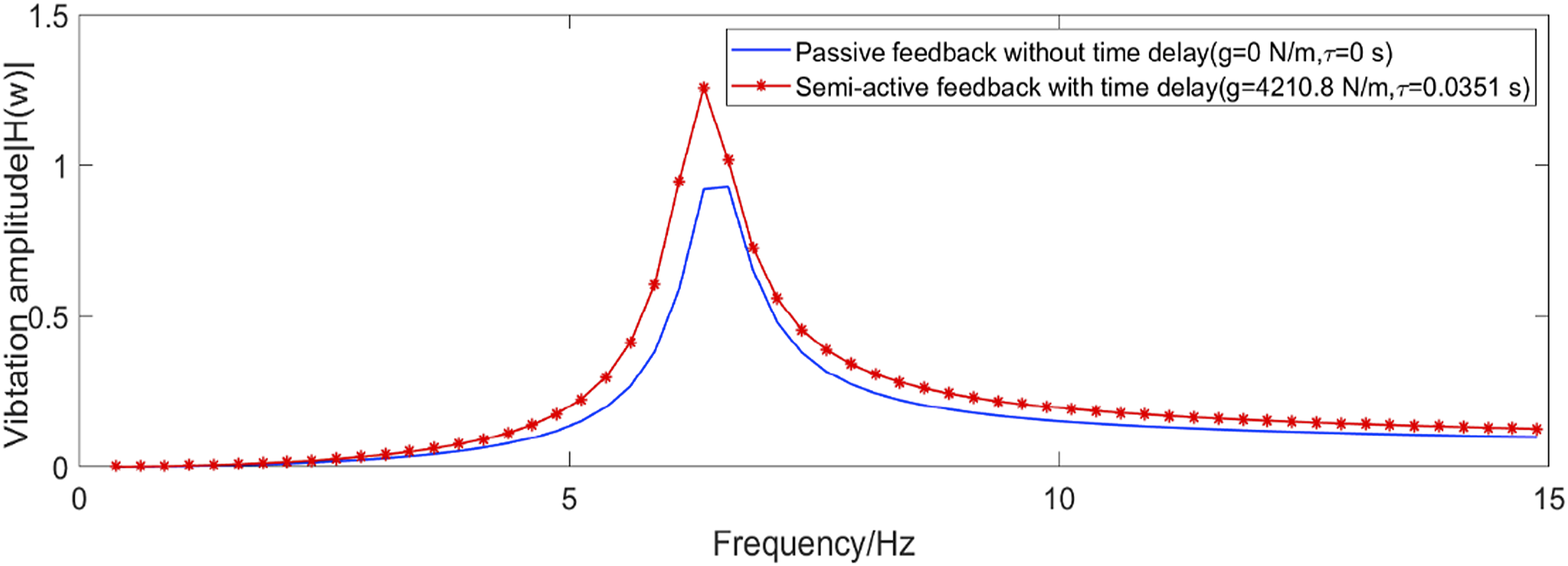
Concerning the optimization results of time-delayed feedback control parameters for the semi-active suspension system within the effective vibration frequency range and its amplitude-frequency characteristics of the vehicle body’s vertical acceleration, the following concise points are elucidated: 1) Analysis of the frequency domain simulation curves of the vehicle body’s vertical acceleration in Figure 2 reveals that, compared to the passively controlled vehicle suspension system, the semi-active suspension system based on wheel vertical displacement time-delayed state feedback control exhibits higher vibration amplitudes at various frequencies within the effective vibration frequency range. Specifically, at frequencies f
mid-j
= 0.25⋅j+0.125, where j=(1, 2, 3,…59), the vibration amplitudes are generally larger than those of the passive suspension system. This is particularly evident at resonance frequencies, where the vibration of the semi-active suspension system becomes more severe, leading to a loss of control effectiveness. In essence, there are certain time-delayed intervals that can increase the vibration amplitude of the vehicle body’s vertical acceleration, suggesting that the selection of these time-delayed feedback control parameters may not be entirely rational. 2) The results of frequency domain simulation analysis for the vehicle body’s vertical acceleration, depicted in Figure 2, reveal the following insights: The semi-active suspension system, employing time-delayed state feedback control based on wheel vertical displacement, causes an increase in the amplitude of the vehicle body’s vertical acceleration from 0.9261 (under passive control) to 1.0147 at f = 6.6250 Hz. Conversely, at f = 6.3750 Hz, the amplitude of the vehicle body’s vertical acceleration rises from 0.9182 (under passive control) to 1.2561 with time-delayed feedback control. The values 0.9261 and 1.2561 represent the vibration peak values of the vehicle body’s vertical acceleration for the passive suspension system and semi-active suspension system, respectively, across the entire frequency range. Therefore, in comparison to passive control, the damping efficiency is −35.63%, indicating that the introduction of time delay leads to instability in the semi-active system. In practical applications, caution should be exercised to avoid tuning the time delay into an unstable range. 3) The frequency domain simulation analysis results for the vertical acceleration of the vehicle body, as depicted in Figure 3, reveal the following: The semi-active suspension system, employing time-delayed state feedback control based on body vertical displacement, leads to a reduction in the amplitude of the vehicle body’s vertical acceleration from 0.9261 (under passive control) to 0.2043 at f = 6.6250 Hz. However, at f = 5.1250 Hz, it results in an increase in the amplitude of the vehicle body’s vertical acceleration from 0.1504 (under passive control) to 0.3943 with time-delayed feedback control. The values 0.9261 and 0.3943 represent the vibration peak values of the vehicle body’s vertical acceleration for the passive suspension system and semi-active suspension system, respectively, across the entire frequency range. When compared to the vibration amplitudes of the vehicle body’s vertical acceleration under passive control, optimal time-delayed feedback control achieves a notable reduction in amplitude, with a damping efficiency of 57.4236%. This enhancement signifies a significant improvement in the damping performance of the vehicle suspension system.
In response to the aforementioned issue of inadequately rational selection of control parameters for feedback control based on the delay state of vertical wheel displacement, efforts are being made to enhance the frequency-response characteristics of the vehicle’s vertical acceleration by adjusting the delay amount. To achieve this improvement, it is essential to re-optimize the determination of optimal values for the delay feedback control parameters. The optimization scheme is outlined below: Amplitude-frequency characteristic curve of vertical acceleration of vehicle body based on time-delayed state feedback control of wheel vertical displacement.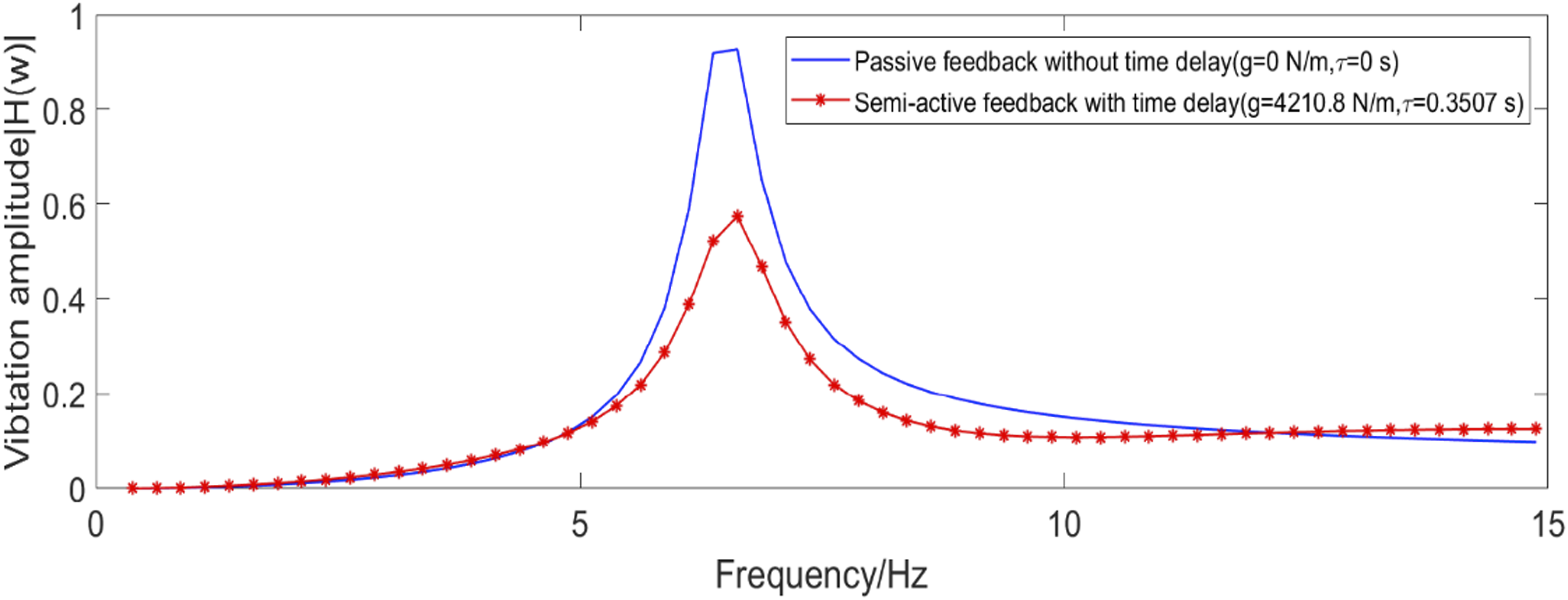
1) Consider the constraint range for the delay feedback control parameters of the vehicle’s semi-active suspension system, which is based on the delay state feedback control of wheel displacement
2) In accordance with the constraints on delay feedback control parameters as depicted in (20), a strategic combination of the equivalent harmonic excitation method and the particle swarm optimization algorithm is employed. Two hundred particles are randomly selected for iterative optimization, leading to the determination of optimal values for delay feedback control parameters under the optimal delay feedback control of the semi-active suspension system. This system is based on the delay state feedback control of vertical wheel displacement within the effective vibration frequency range, resulting in optimal values of “(g wop ,τ wop )=(4210.8 N/m, 0.3507 s).” Furthermore, the amplitude-frequency characteristics curve of the vehicle’s vertical acceleration under optimal delay feedback control, as illustrated in Figure 4, is presented for the effective vibration frequency range.
3) The frequency domain simulation results illustrated in Figure 4 reveal that, in comparison to passive control, the semi-active suspension system incorporating wheel displacement delay state feedback control achieves a notable reduction in the vibration amplitude of the vehicle’s vertical acceleration at f = 6.6250 Hz. Specifically, the amplitude decreases from 0.9261 under passive control to 0.5743 under delay feedback control. These values represent the peak vibrations for the passive suspension system and the semi-active suspension system based on wheel displacement delay state feedback control across the entire frequency range. As a result, the vibration reduction efficiency is calculated to be 37.9873%. Consequently, the application of wheel displacement delay state feedback control, when contrasted with passive control, effectively mitigates the amplitude of the vehicle’s vertical acceleration, showcasing an enhancement in the damping performance of the automobile suspension system.
To ensure the stable operation of the semi-active suspension system utilizing delay state feedback control for both vertical wheel displacement and vertical body displacement, it is crucial to determine the optimal values for the delay feedback control parameters. The stability analysis of the vehicle’s semi-active suspension system, incorporating delay state feedback control, is conducted through the use of Maple programs and frequency-domain scan stability theory.33,34 This analysis aims to define the stability interval for the semi-active suspension system with delay feedback control. The analytical process is outlined as follows:
Initially, employing equations (13) and (14), we derive the characteristic equations for the semi-active suspension system based on delay state feedback control of vertical wheel displacement and vertical body displacement, respectively

In accordance with the Routh–Hurwitz criterion, the requisite condition for system stability is that all the characteristic roots of equations (21) and (22) possess negative real parts. The critical condition for system instability occurs when the characteristic roots of the equation are purely imaginary, denoted as s = iω. Consequently, by substituting s = iω and the optimal values of the delay state feedback control parameters based on vertical wheel and body displacement into the characteristic equation, and subsequently isolating the real and imaginary components of the characteristic equation, the following expressions can be obtained

1. In accordance with the optimal values of the delay feedback control parameters (g
wop
= 4210.8 N/m) for the semi-active suspension system utilizing delay state feedback control based on vertical wheel displacement, the Maple program was utilized for computation. The outcomes yield the expressions for z
w
(s), P
w
(s), and Q
w
(s) in equation (23) as follows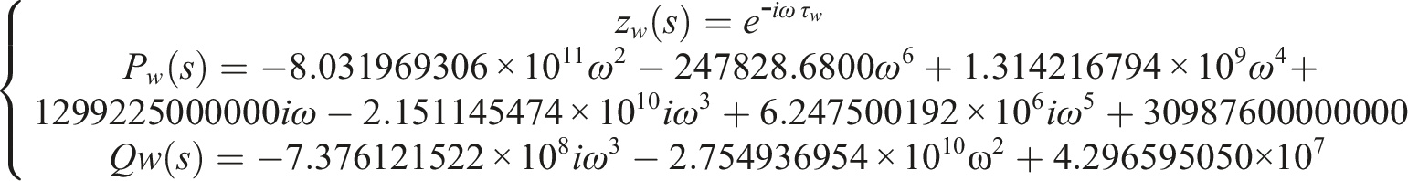
2. In accordance with the optimal values of the delay feedback control parameters (g
bop
= 4210.8 N/m) for the semi-active suspension system with delay state feedback control based on vertical body displacement, the Maple program is employed for computation. The results provide the expressions for z
b
(s), P
b
(s), and Q
b
(s)in equation (24) as follows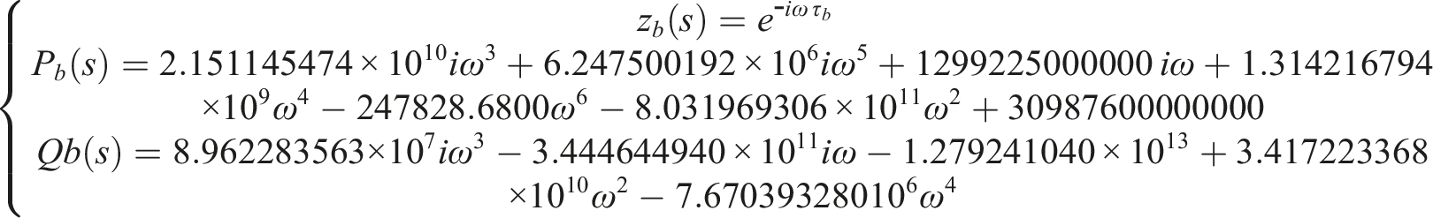
Moreover, in the presence of polynomials L
w
(s) = P
w
(s)/Q
w
(s) and L
b
(s) = P
b
(s)/Q
b
(s), equations (20) and (21) can be expressed equivalently as

In accordance with equations (21) and (22), by substituting the Maple-program-computed values of P
w
(s), Q
w
(s)for delay state feedback control based on vertical wheel displacement, and P
b
(s), Q
b
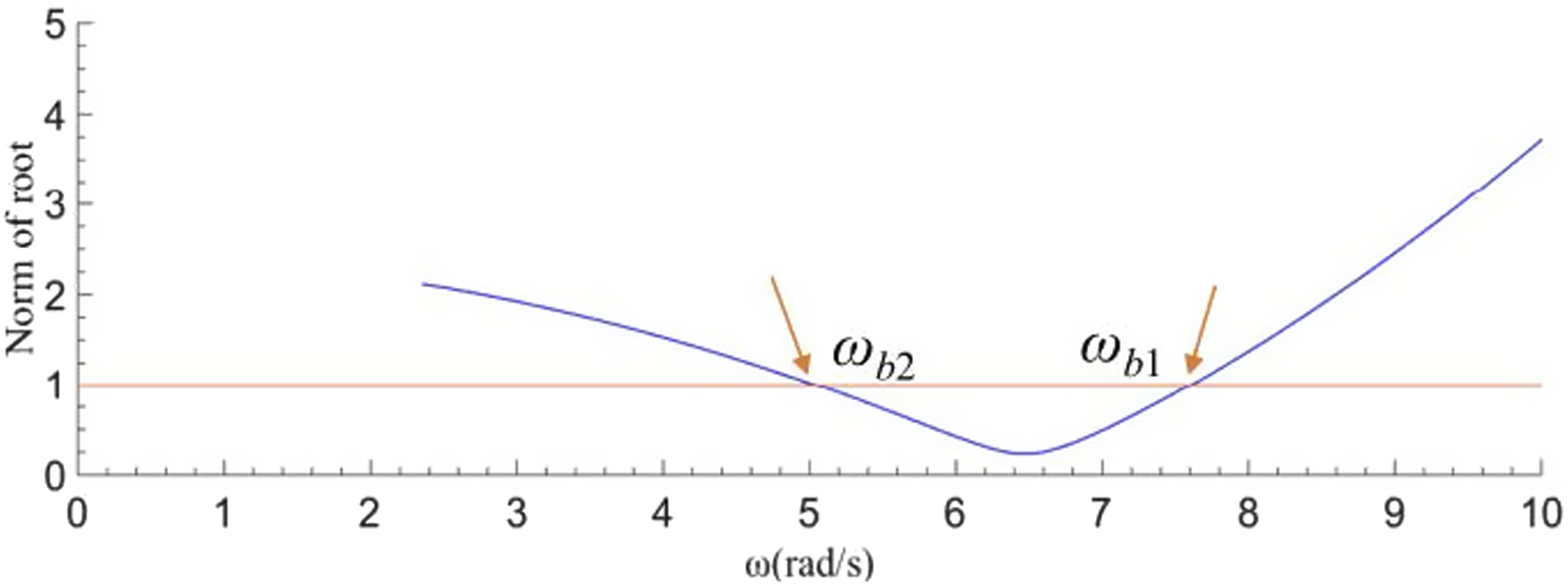
(s) for delay state feedback control based on vertical body displacement into equations (25) and (26), respectively, we can derive the relationships between the modulus |z| = 1 of the complex roots of the characteristic equations and the crossover frequency ω(rad/s). These relationships are depicted in Figures 5 and 6, illustrating the characteristics of the semi-active suspension system with delay state feedback control based on vertical wheel and body displacement, respectively. Modulus of complex root of characteristic equation of vehicle semi-active suspension system with time-delayed state feedback control of wheel vertical displacement. Modulus of complex root of characteristic equation of vehicle suspension system with time-delayed state feedback control of vertical displacement of vehicle body.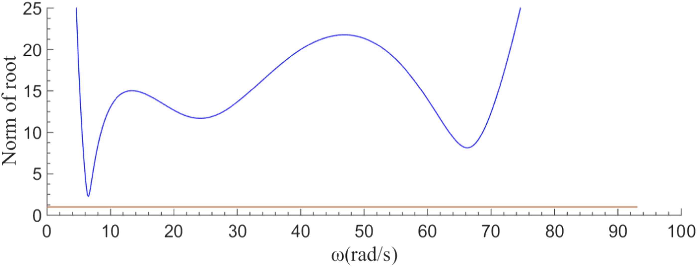
Finally, calculate the cross frequencies ω
w
and ω
b
, as well as their corresponding critical time delay values τ
w
and τ
b
, for the vehicle semi-active suspension system based on wheel vertical displacement and body vertical time-delayed state feedback control. 1. From Figure 5, it can be observed that, for the vehicle’s semi-active suspension system utilizing feedback control based on wheel displacement time-delay, the modulus |z| = 1 of the complex roots of the characteristic equation does not intersect with the frequency ω (rad/s) line, indicating no crossing at the frequency ω
w
(rad/s). Therefore, it can be inferred that the vehicle’s semi-active suspension system is globally stable with time delay when g
wop
= 4210.8 N/m, and τ
wop
∈(0.0001 s, 1 s). 2. From Figure 6, it can be observed that the semi-active suspension system of the vehicle, employing time-delayed state feedback control based on body vertical displacement, exhibits two crossing frequencies, namely ωb1 and ωb2. Utilizing a numerical solution method for steady-state equations, the real roots of the crossing frequencies are determined as ωb1 = 7.6070 rad/s and ωb2 = 5.0381 rad/s, respectively. Further investigation reveals that the critical time delays corresponding to these frequencies are τb1 = 0.3755 + 0.2629rπ (r = 0, 1, 2, …, ∞) for ωb1 = 7.6070 rad/s, where the characteristic roots will traverse the imaginary axis from left to right, increasing the number of unstable characteristic roots in the characteristic equation (22). Similarly, for ωb2 = 5.0381 rad/s, the critical time delay is τb2 = 0.0353 + 0.3969rπ (r = 0, 1, 2, …, ∞), and the characteristic roots will traverse from right to left, reducing the number of unstable characteristic roots. Therefore, the system achieves asymptotic stability when g
bop
= 4210.8 N/m, and τ
bop
∈(0.0353 s, 0.3755 s). However, the previously optimized time delay value is τ
bop
= 0.0351 s, indicating that the choice of the time delay is not entirely rational, resulting in an unstable operational state of the system. Consequently, a re-optimization of the time-delayed feedback control parameters for the vehicle’s semi-active suspension system is deemed necessary.
In response to the previously noted issue of suboptimal selection of time-delayed feedback control parameters for the semi-active suspension system based on body vertical displacement, an approach is proposed to enhance the system’s stability through adjustments to the time-delay parameters. The proposed technical plan is outlined as follows: • Firstly, an attempt will be made to refine the stability of the vehicle’s semi-active suspension system by adjusting the time-delay parameters. This involves exploring alternative numerical ranges for the time delay, while maintaining the constraints on the feedback gain coefficient in the strategy. The constraints on the time-delayed feedback control parameters for the semi-active suspension system based on body vertical displacement will remain unchanged • Moreover, in light of the constraints outlined in equation (24) for time-delay feedback control parameters, a strategy is proposed that combines the equivalent harmonic excitation method with the particle swarm optimization algorithm. This strategy is designed to formulate a particle swarm optimization algorithm based on equation (24), utilizing J (g
b
, τ
b
) as the fitness function. To further enhance the vibration bandwidth and damping effectiveness of the vehicle suspension system, which employs body vertical displacement time-delayed feedback control under random road excitations, a frequency domain expression for the vertical acceleration of the body relative to the road input, represented as

Under the assumption that the peak values of road excitations at the center frequencies f mid-j = 0.25j+0.125 (where j = 1, 2, 3, …, 59) within each subinterval of the effective vibration frequency range are denoted as |x q (f mid-j )|, this approach aims to effectively prevent the optimization results of the time-delay feedback control parameters from converging to local optima.
Expanding on the optimization strategy for time-delayed feedback control parameters mentioned earlier, a set of 200 particles was randomly chosen for iterative optimization. This approach resulted in obtaining the optimal values for time-delayed feedback control parameters within the effective vibration frequency range under the optimal time-delayed feedback control, specifically (g
bop
, τ
bop
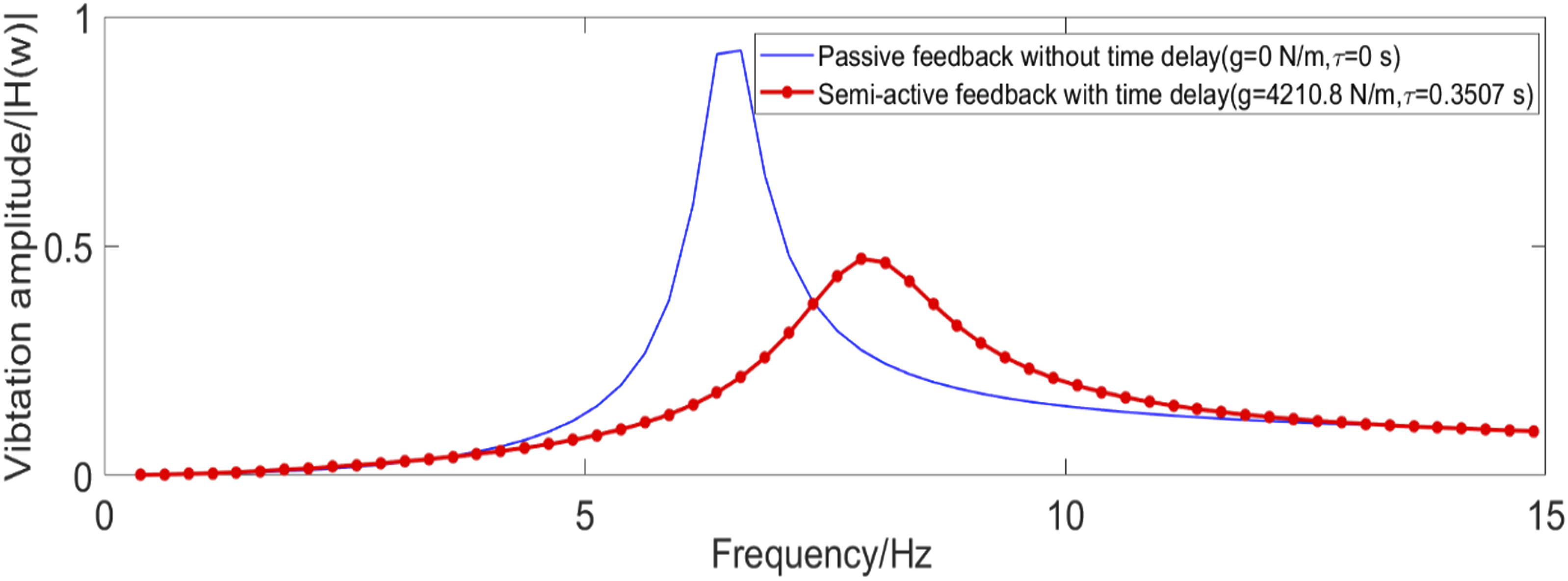
)=(4210.8 N/m, 0.3507 s). Furthermore, Figure 7 illustrates the amplitude-frequency characteristic curve for the vertical acceleration of the vehicle body within the effective vibration frequency range under the optimal time-delayed feedback control. • Finally, with regard to the amplitude-frequency characteristics of vertical acceleration under optimal time-delayed feedback control and the time-delay stability of the vehicle’s semi-active suspension system, the following explanations are provided: 1. Analysis of the frequency domain simulation curve of vertical acceleration in Figure 7 reveals that, compared to passive control, the optimal time-delayed feedback control results in a reduction in the amplitude of vertical acceleration. This reduction suggests an enhancement in the isolation effectiveness of the vehicle suspension system. 2. The frequency domain simulation results for vertical acceleration in Figure 7 demonstrate that time-delayed feedback control based on body vertical displacement, under optimal conditions, decreases the vibration amplitude of vertical acceleration from 0.9261 under passive control to 0.2139. However, at f = 7.8750 Hz, it increases the amplitude from 0.2730 under passive control to 0.4714. These values represent the peak vertical acceleration amplitudes within the effective vibration frequency range for passive suspension and semi-active suspension systems, respectively. Consequently, the optimization efficiency of vertical acceleration is calculated at 49.0983%. Clearly, compared to passive control, the semi-active suspension system with time-delayed feedback control based on body vertical displacement effectively suppresses the amplitude of vertical acceleration within the effective vibration frequency range. 3. Considering the analysis results regarding the time-delay stability of the semi-active suspension system based on body vertical displacement time-delayed feedback control, specifically when g
bop
= 4210.8 N/m and τ
bop
∈(0.0353 s, 0.3755 s), the system is deemed asymptotically stable. Therefore, with g
bop
= 4210.8 N/m and τ
bop
= 0.3507 s, the vehicle’s semi-active suspension system achieves stability under time-delayed feedback control. Amplitude-frequency characteristic curve of body vertical acceleration controlled by time-delay state feedback of body vertical displacement.
Time-domain simulation analysis and validation
To validate the accuracy of the optimized time-delayed feedback control parameters, it is crucial to utilize the optimal values for the time-delayed feedback control parameters in the semi-active suspension system of the vehicle. Employing a time-domain analysis method, simulation analyses will be conducted on the time-domain responses of both the vehicle’s semi-active suspension and the seat suspension, both incorporating time-delayed feedback control. Furthermore, a comprehensive comparative analysis will systematically contrast the time-domain responses and various performance evaluation indicators of the suspension systems and seat suspension systems under time-delayed feedback control with those under passive control.
Based on the optimized solutions obtained for the time-delayed feedback control parameters associated with wheel vertical displacement and body vertical displacement, specifically “(g
wop
,τ
wop
)=(4210.8 N/m, 0.3507 s)” and “(g
bop
, τ
bop
)=(4210.8 N/m, 0.3507 s),” numerical simulation analyses of various performance evaluation indicators for the vehicle’s semi-active suspension system and seat suspension system under Class-C road surface roughness excitation were conducted. This resulted in obtaining the time-domain response simulation curves for the performance evaluation indicators of the semi-active suspension system based on wheel and body vertical displacement time-delayed feedback control, as depicted in Figures 8 and 9, along with the time-domain response simulation curve for seat vertical acceleration. Time domain simulation curve of various performance evaluation indexes of time-delayed state feedback control of wheel vertical displacement. (a) Seat vertical acceleration, (b) body vertical acceleration, (c) suspension dynamic stroke, (d) tire dynamic displacement, (e) body vertical displacement. Time domain simulation curve of various performance evaluation indexes of time-delayed state feedback control of body vertical displacement. (a) Seat vertical acceleration, (b) body vertical acceleration, (c) suspension dynamic stroke, (d) tire dynamic displacement, (e) body vertical displacement.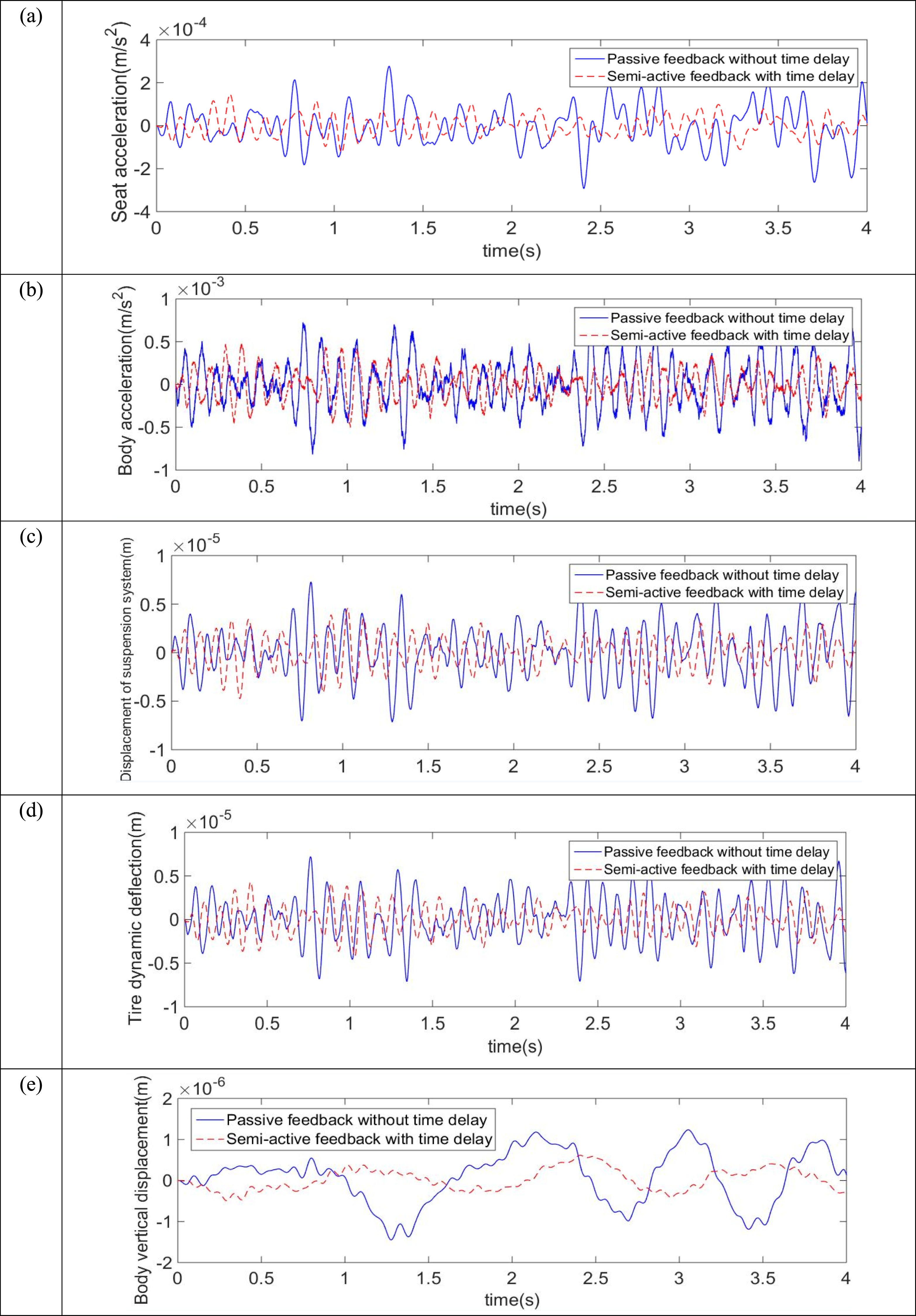
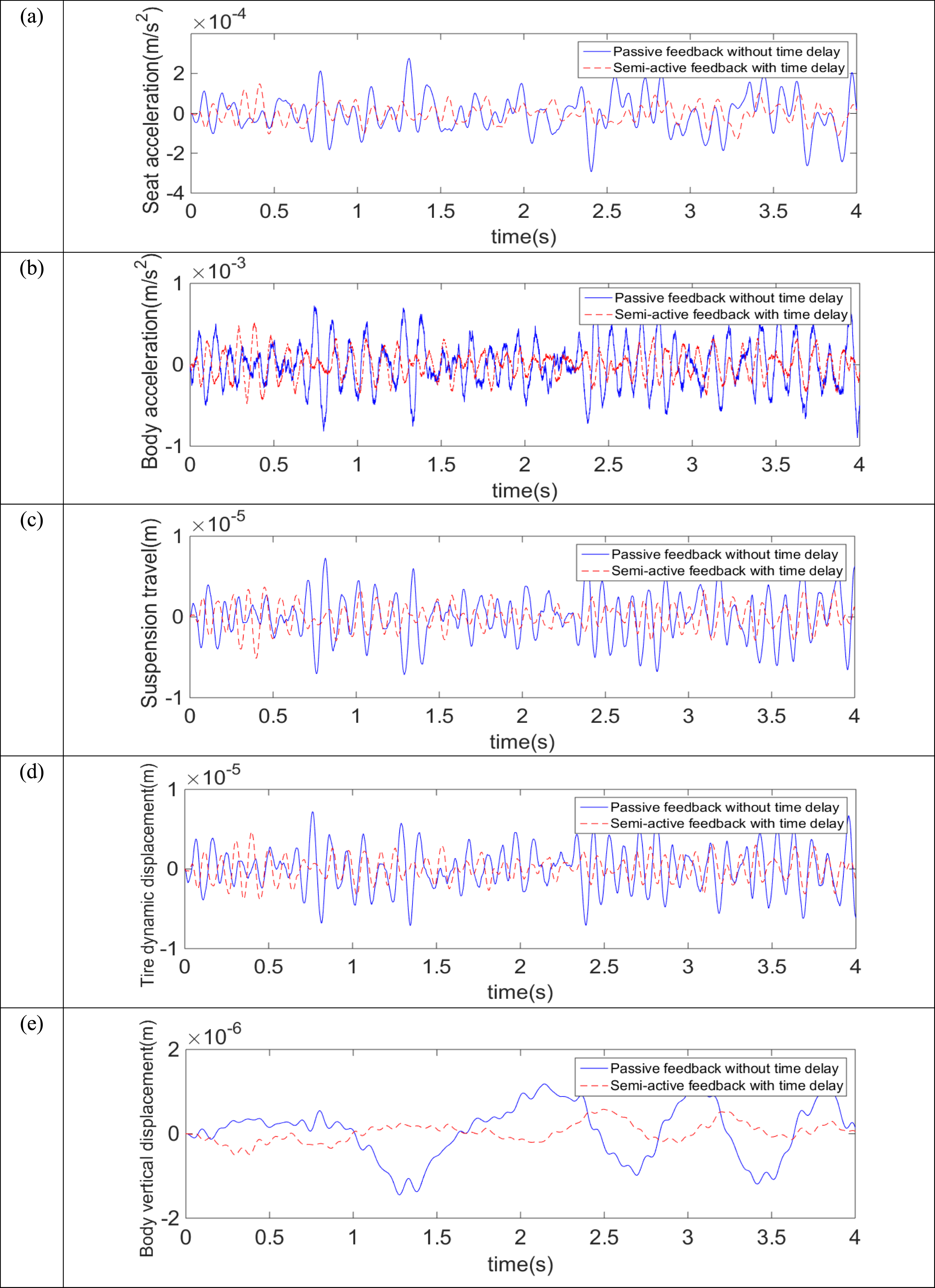
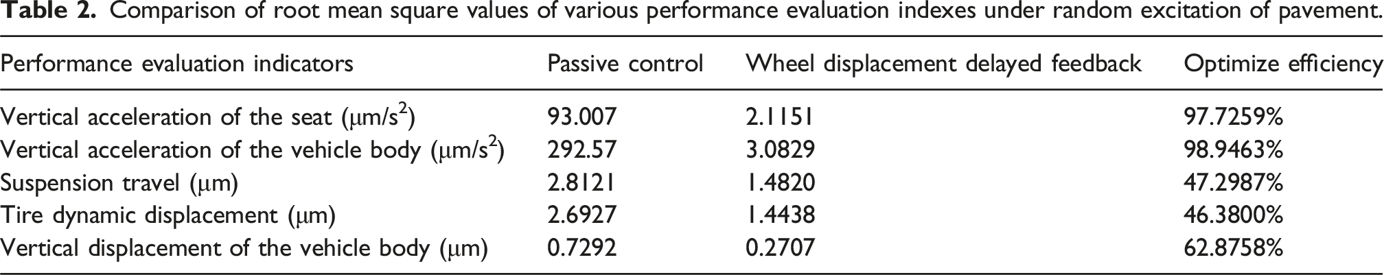
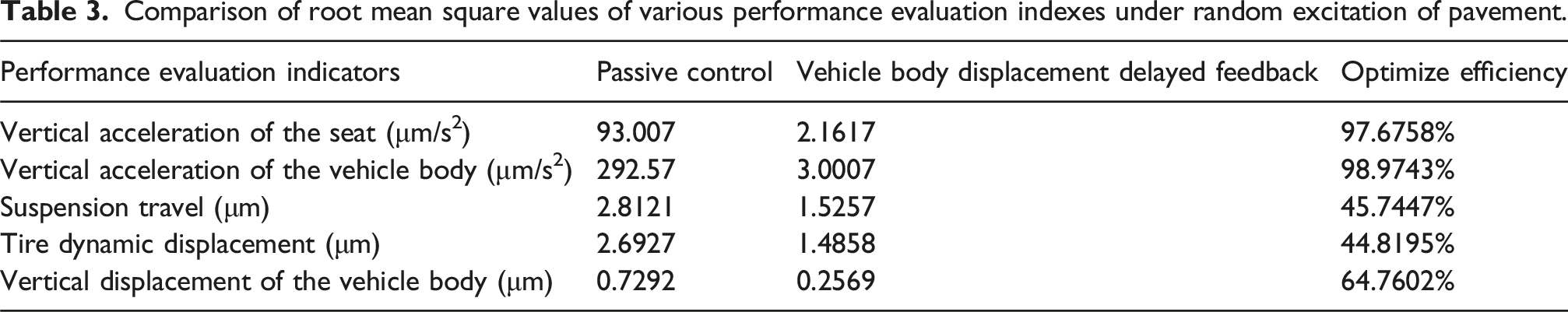
Investigating the influence of time-delayed feedback control parameters on system vibrations using different time-delayed feedback control strategies. Based on the comparison of root mean square values of various vehicle performance evaluation indicators as presented in Tables 2 and 3, the following key conclusions can be drawn: 1. Compared to the passive control of the vehicle suspension system, the semi-active suspension system based on time-delayed feedback control notably reduces the vibration amplitude of the seat’s vertical acceleration. The corresponding root mean square values decrease from 93.007 μm/s2 under passive control to 2.1151 μm/s2 and 2.1617 μm/s2 under time-delayed feedback control based on wheel and body vertical displacement, respectively. This represents an optimization efficiency of 97.7259% and 97.6758%. Consequently, there is a significant enhancement in the driver’s ride comfort during the vehicle’s operation. 2. In comparison to the passive control of the vehicle suspension system, the semi-active suspension system based on time-delayed feedback control significantly reduces the vibration amplitude of the body’s vertical acceleration. The corresponding root mean square values decrease from 292.57 μm/s2 under passive control to 3.0829 μm/s2 and 3.0007 μm/s2 under time-delayed feedback control based on wheel and body vertical displacement, respectively. This represents an optimization efficiency of 98.9463% and 98.9743%. Consequently, there is a substantial improvement in the smoothness and ride comfort during the vehicle’s operation. 3. Compared to the passive control of the vehicle suspension system, the semi-active suspension system based on time-delayed feedback control significantly reduces the vibration amplitude of the suspension travel. The corresponding root mean square values decrease from 2.8121 μm under passive control to 1.4820 μm and 1.5257 μm under time-delayed feedback control based on wheel and body vertical displacement, respectively. This represents an optimization efficiency of 47.2987% and 45.7447%. Consequently, the probability of impact on the bump stops is substantially reduced. This not only enhances ride comfort but also improves the safety of the vehicle chassis. 4. Compared to the passive control of the vehicle suspension system, the semi-active suspension system based on time-delayed feedback control significantly reduces the vibration amplitude of tire dynamic displacement. The corresponding root mean square values decrease from 2.6927 μm under passive control to 1.4438 μm and 1.4858 μm under time-delayed feedback control based on wheel and body vertical displacement, respectively. This represents an optimization efficiency of 46.3800% and 44.8195%. Consequently, it effectively enhances the tire’s grip on the ground, significantly improving the vehicle’s handling stability. 5. In comparison to the passive control of the vehicle suspension system, the semi-active suspension system based on time-delayed feedback control significantly reduces the vibration amplitude of the body’s vertical displacement. The corresponding root mean square values decrease from 0.7292 μm under passive control to 0.2707 μm and 0.2569 μm under time-delayed feedback control based on wheel and body vertical displacement, respectively. This represents an optimization efficiency of 62.8758% and 64.7602%. In essence, the smoothness of the vehicle’s ride is markedly enhanced. Comparison of root mean square values of various performance evaluation indexes under random excitation of pavement. Comparison of root mean square values of various performance evaluation indexes under random excitation of pavement.
The results from the time-domain simulation analysis of the semi-active suspension system based on time-delayed feedback control under random road excitations reveal the following: In comparison to the integrated optimal control strategy that combines both the vehicle’s active suspension and the seat’s active suspension, employing a single time-delayed feedback control strategy based on either body vertical displacement or wheel vertical displacement alone, the quarter-car suspension system based on time-delayed feedback control for both wheel and body vertical displacement significantly improves various performance evaluation indicators. This improvement is evident in the enhanced ride comfort, handling stability, and safety of the vehicle, as well as the comfort experienced by the driver during the vehicle’s operation.
Conclusions
Based on the optimized values of the time-delayed feedback control parameters, a numerical simulation analysis and validation of various performance evaluation indicators for the semi-active suspension system, incorporating time-delayed feedback control of both wheel and body vertical displacement under road excitations, yield the following main conclusions: 1. In contrast to the passive control of the vehicle suspension system, the semi-active suspension system, under optimal time-delayed feedback control, significantly enhances the smoothness, handling stability, and safety of vehicle operation. This comprehensive improvement in the overall performance of the vehicle suspension system effectively resolves the historical issue of conflicting performance evaluation indicators in semi-active suspension systems under random road excitations. Additionally, the effectiveness of the equivalent harmonic excitation optimization algorithm is clearly demonstrated. 2. Under optimal time-delayed feedback control, the semi-active suspension system controlled by the strategy based on time-delayed feedback control of both wheel and body vertical displacement exhibits nearly identical time-delay damping control effects under random road excitations. Moreover, the system based on time-delayed feedback control of wheel vertical displacement is more likely to achieve a fully stable state within the effective vibration frequency range. 3. The semi-active suspension system for vehicles, based on time-delayed state feedback control, resolves the historical contradiction between seat suspension and vehicle suspension performance indicators when exclusively employing vehicle semi-active suspension control. Specifically, the optimal time-delayed feedback control ensures a more accurate and objective evaluation of the vehicle’s smoothness by considering the vertical acceleration of the seat. This accomplishment represents a comprehensive optimization in the design of vehicle vibration control. Consequently, it not only lends robust support to the optimization of vehicle semi-active suspension systems but also establishes a firm theoretical foundation for the selection of delayed feedback control strategies.
Future research
Compared to other optimization algorithms, the Particle Swarm Optimization (PSO) algorithm used in this paper is relatively simple, easy to understand, and well-suited for single-objective optimization. It also outperforms others in terms of optimization speed and vibration reduction. By combining a multi-objective optimization approach based on genetic algorithms, a comprehensive objective function can be developed using various performance indicators of the vehicle’s semi-active suspension system, such as vertical acceleration, suspension dynamic travel, and tire dynamic displacement. Minimizing the root mean square (RMS) values of these indicators leads to a more comprehensive and balanced optimization solution. This method emphasizes the trade-off between competing objectives, enabling overall system optimization while ensuring the performance requirements are met.
Therefore, future research on time-delayed vibration control in vehicle semi-active suspension systems should carefully consider and integrate other specialized control methods. For instance, in future research, the Non-dominated Sorting Genetic Algorithm (NSGA-II) could be employed to optimize and determine the optimal values of time-delay feedback control parameters, with a focus on enhancing the performance of vehicle semi-active suspension systems and controlling time-delay vibrations through multi-objective optimization.