
Abstract
Designing a rubber vibration isolator to simultaneously meet the requirements on both low-frequency vibration isolation and high load carrying capacity has always been a major challenge. To tackle this problem, in this paper, a design strategy capable of effectively balancing these two effects to guide the design of such isolators is proposed. The rubber isolator static and dynamic behavior prediction models suitable for engineering applications are first established, where Yeoh model is adopted for rubber strong nonlinear feature prediction. Experiments are carried out to determine the material constants in Yeoh model and dynamic-to-static ratio of the rubber material. Combing with Multi-Objective Genetic Algorithm, a design strategy is proposed. The conducted experiments demonstrate that based on the proposed numerical model and design procedure, rubber isolators with enough load bearing capability and low-frequency vibration isolation performance can be successfully designed.
Keywords
Introduction
The marine propulsion systems exhibit a trend towards increased weight and power as well as decreased operational speed, which however, poses a significant challenge in terms of noise and vibration control due to the generation of low-frequency vibration and noise as well as the high load-bearing requirement.
Vibration isolation technology is one of the most critical technologies in the field of vibration and noise control in mechanical engineering. Rubber vibration isolators are widely used to isolate the vibration of marine power machinery due to their simple structure, high damping, low cost, and nonlinearity.1–4 Extensive amount of papers have been published on the subject of rubber vibration isolators, ranging from effective modelling the static and dynamic performance of rubber material5–12 or isolators1,13–18 to various applications, like in marine diesel engines,19,20 bridges, 21 railway, 22 automobiles,23,24 aerospace, semiconductor engineering,25–27 etc.
When rubber isolators are applied to marine power machinery to support heavy weight and meet low-frequency vibration isolation requirements, it is essential to enhance their performance to ensure sufficient load carrying capacity and effective low-frequency vibration isolation simultaneously. However, achieving this balance is technically challenging, as improving vibration isolation often compromises load-bearing capacity, and vice versa. This dual challenge forms a critical gap in the current state of vibration isolation technology, motivating the need for innovative solutions that do not force a trade-off between these two essential aspects.
Efforts to develop the low-frequency vibration isolation performance of the rubber vibration isolator by reducing the isolator dynamic stiffness or the resonant frequency have been persistent. The dynamic characteristics of rubber isolators depend on various parameters including the preload, excitation amplitude, and excitation frequency.28–30 To describe the dynamic characteristics of rubber isolator, various models have been proposed including the Maxwell, 8 Kelvin-Voigt, 9 BERG, 10 modified boundary surface model, 11 and the viscoelastic fractional derivative model. 12 Gil-Negrete et al. 31 proposed a simplified methodology to predict the dynamic stiffness of carbon-black filled rubber isolators using a finite element code, which can be used to guide the reduction of the dynamic stiffness of rubber vibration isolators to enhance the low-frequency vibration reduction effect. Seung et al. 32 adopted deep learning as structural optimization method to design the rubber vibration isolator into an arch bridge shape for perfect vibration damping. By using the Bragg scattering and local resonance induced band gaps, Jin et al. 33 designed a rubber isolator with a four-layer honeycomb meta-structure to achieve ultra-wide and low-frequency vibration isolation. However, when it comes to vibration isolators, their low-frequency vibration isolation effect comes first, and there is not much attention paid to load-bearing capacity. Meanwhile, although existing dynamic models can effectively reflect the dynamic characteristics of rubber isolators, extensive experiments are required to determine unknown parameters in these models, rendering them impractical in engineering. This gap in practical applicability further underscores the need for a more holistic approach to rubber isolator design, one that can balance low-frequency isolation with the necessary load support in real-world conditions.
To increase the load carrying capacity or the static stiffness of the rubber isolators, various empirical formulae34,35 are developed to predict the static stiffness of the rubber isolators; however, these formulae only applicable for isolators with regular shape and small deformation.34,36 Meanwhile, additives are usually added to rubber to increase the hardness of the rubber material and the static stiffness of the rubber isolator.37–41 For example, Kuteneva et al. 39 studied the influences of the additives on the load-carrying capacity of the vibration isolator from a microscopic point of view. Murali Manohar et al. 40 studied the hardness of nitrile rubber and rubber–polyvinyl chloride hybrid vulcanizates reinforced with high abrasion furnace carbon black (CB-HAF) and graphite (GT). It was found that CB-HAF had a greater effect on the hardness enhancement of the material compared to GT. The maximum increase in hardness was observed at a CB-HAF volume fraction of 0.12. Abdul Wahab et al. 41 compared the mechanical properties of rubber vulcanizates containing Ethylene Propylene Diene Rubber waste at different types of vulcanization system. The results show that different vulcanization systems could have different effects on the hardness of rubber materials. However, these methods primarily focus on enhancing the static stiffness, often at the cost of increased resonant frequency, which conflicts with the goal of low-frequency vibration isolation. The need for a more comprehensive approach that can simultaneously optimize both static stiffness and dynamic isolation is therefore crucial.
While shedding light on the design of rubber isolators, existing studies have been overwhelmed by cases, in which, only the low-frequency vibration isolation performance or the load carrying capacity of rubber isolators is considered and the investigated rubber isolator usually has small deformation with relatively high resonance frequency, which, in a rigorous sense, cannot provide guidance for the design of rubber isolators with both strong load-carrying capacity and low resonant frequency.
Developing rubber isolators that can withstand heavy weight and meet the low-frequency vibration isolation requirements of marine power machinery simultaneously requires meticulous design. However, the effective handling of such complex problem in terms of design, modelling and optimization is technically challenging due to the stringent requirements on the simulation and optimization tools, especially when dealing with rubber material under large deformation exhibiting strong nonlinear features, along with the need for cost control in engineering applications.
Motivated by these challenges, we aim to provide a practical solution that integrates advanced modeling techniques and optimization strategies to develop rubber isolators that can perform effectively under the demanding conditions of marine applications. In this study, a strategy to guide the design of the rubber isolator with both low-frequency vibration isolation performance and strong bearing capacity is proposed. The Yeoh model is selected to improve the calculation accuracy of rubber vibration isolators under large deformation. Experiments determining the material constants in Yeoh model and the dynamic-to-static ratio of the rubber material are designed and carried out. After this, the rubber isolator static and dynamic behavior prediction model suitable for engineering applications are established. Next, based on the established models, the influence of structural parameters on the performance of the rubber isolators is analyzed. A design procedure using a genetic algorithm is proposed to optimize parameters for best low-frequency vibration isolation and high load bearing capacity. The conducted experiments demonstrate that the proposed numerical model and design procedure can successfully design rubber isolators with sufficient load-bearing capability and low-frequency vibration isolation performance.
Nonlinear rubber material hyperelasticity model
Rubber hyperelasticity model
The original general expression for strain energy W was proposed by Rivlin in 1951:

Our research primarily focuses on rubber vibration isolators with large deformations. Therefore, the Yeoh model is selected, which assumes that the second strain invariant

The three-parameter form of the Yeoh model can be expressed as follows:

The relationship between the stretch ratio
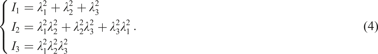
For rubber materials:

The relationships between the various fundamental tests of rubber material are as follows: iso-biaxial compression is equivalent to uniaxial tension (UT), pure shear is equivalent to plane tension (PT), and uniaxial compression is equivalent to iso-biaxial tension (BT). Given the limitations of the experimental conditions, UT, PT and BT tests are typically employed to determine the material constants in the hyperelastic intrinsic model of rubber materials.
In fact, due to the existence of various influencing factors in the testing process, the stress and strain obtained are often engineering stress


For UT, the stress is solely present in the tension direction, with zero stress in the other two directions. Consequently, the relationship between


According to equations (3), (9) and (11), the relationship between

The above described stress-strain relationship can be further transformed into equation (13) below. Once the material constants

Rubber material dynamic-to-static ratio determination
The dynamic-to-static ratio (DSR) of rubber material is a crucial parameter for predicting the dynamic performance of rubber vibration isolators. Accurately determining this ratio is essential because the dynamic stiffness of rubber materials differs significantly from their static stiffness, especially when subjected to vibrations. The DSR of rubber helps in modeling this difference, providing a more precise prediction of how the rubber isolator will behave under dynamic conditions compared to static ones.
Here, we define that the ratio of dynamic to static stiffness of the isolator as the dynamic-to-static ratio (DSR) of the rubber vibration isolator, which can be described as
Experiments
Rubber vibration isolators
The rubber vibration isolator studied in this work, as depicted in Figure 1, is cylindrical and vertically symmetric. It comprises two metal rings bonded together with rubber. The outer metal ring maintains a uniform thickness, whereas the thickness of the inner metal ring decreases gradually from the midpoint to the edges. Thus, the wall of the inner metal ring is inclined at a specific angle. Consequently, the geometry parameters determine the structure of the rubber vibration isolator include the height ( Three-dimensional diagram of rubber vibration isolator (a) the overall structure and (b) detailed inner structure with illustrations on structural parameters.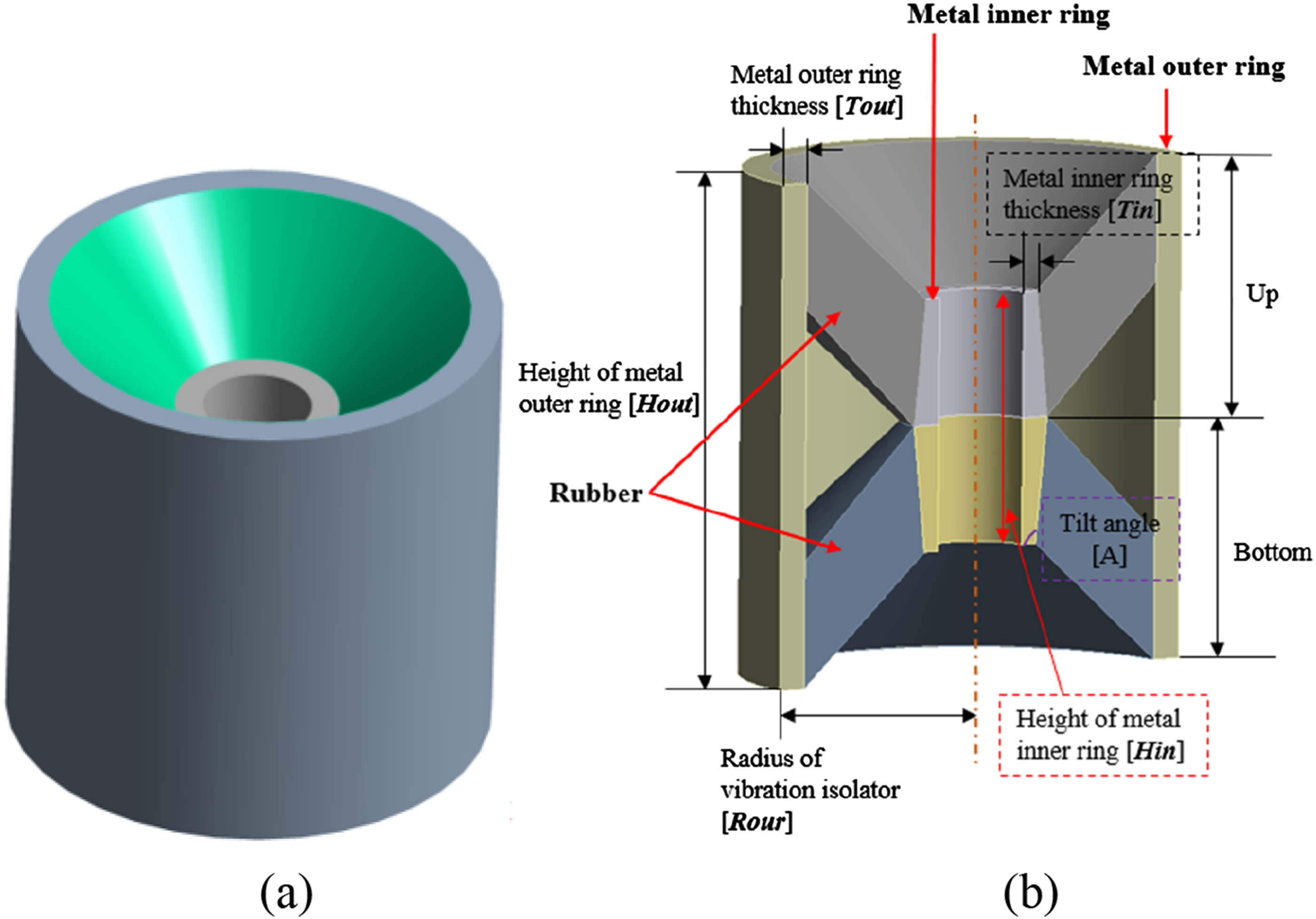
The rubber vibration isolator described in this work features a unique and meticulously engineered design. The specific inclination of the inner ring fulfils a number of important functions. Firstly, it assists in the uniform distribution of the load across the rubber element, thereby reducing the likelihood of stress concentrations that can lead to premature failure or uneven wear. Secondly, the inclined geometry enhances the energy absorption capability of the isolator by allowing the rubber to deform in a more uniform manner during operation. This enhances the isolator’s ability to accommodate substantial deformations and pronounced nonlinearities, which are prevalent in practical applications such as marine and industrial settings. Additionally, the inclination angle is crucial in tuning the stiffness and dynamic performance of the isolator. By varying this angle, it is possible to tailor the isolator behavior to meet specific low-frequency vibration isolation requirements while maintaining sufficient load-carrying capacity. This design flexibility makes the isolator adaptable to various engineering applications where both high performance and durability are needed.
Geometrical parameters of manufactured rubber vibration isolators.
Experiments on static characteristics of rubber vibration isolators
The experiments conducted to obtain the static and dynamic characteristics of rubber vibration isolators are carried out in accordance with ICS 17.160 (Vibration and shock isolators – Measuring method for its static and dynamic characteristics).
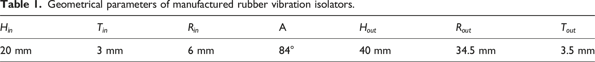
The rubber isolator static stiffness test setup is shown in Figure 2. The test setup comprises a flat test stand on which the rubber vibration isolator is placed. A screw is attached to the center of the inner ring of the isolator (Figure 2(a)), enabling precise force application via the connected screw (Figure 2(b)). The force is applied vertically to simulate the real operational conditions experienced by the isolator during loading. Rubber vibration isolator static stiffness test setup (a) screw and isolator; (b) zoomed-in view; (c) overall view.
The static stiffness of the rubber vibration isolator is determined from its load-displacement curve, obtained by applying a force on the isolator from 0 to 1.25 times the rated load. Displacement is recorded using the displacement sensors integrated into the testing machine, ensuring accurate measurement of the deformation of the isolator under each load step. The machine used for testing is the AI-7000-LA5 from GOTECH TESTING MACHINES INNC (Dongguan), which is equipped with high-precision load and displacement sensors to ensure measurement accuracy. The static stiffness of rubber vibration isolator
It is important to note that in order to obtain accurate load—displacement data for a rubber isolator, it is necessary to carry out three loading and unloading cycles prior to testing to minimize the well-documented Mullins effect.
43
The tested relationship between static load and deformation of the tested isolators are shown in Figure 3. Static load-deformation relationship curves (a) isolator A and (b) isolator B.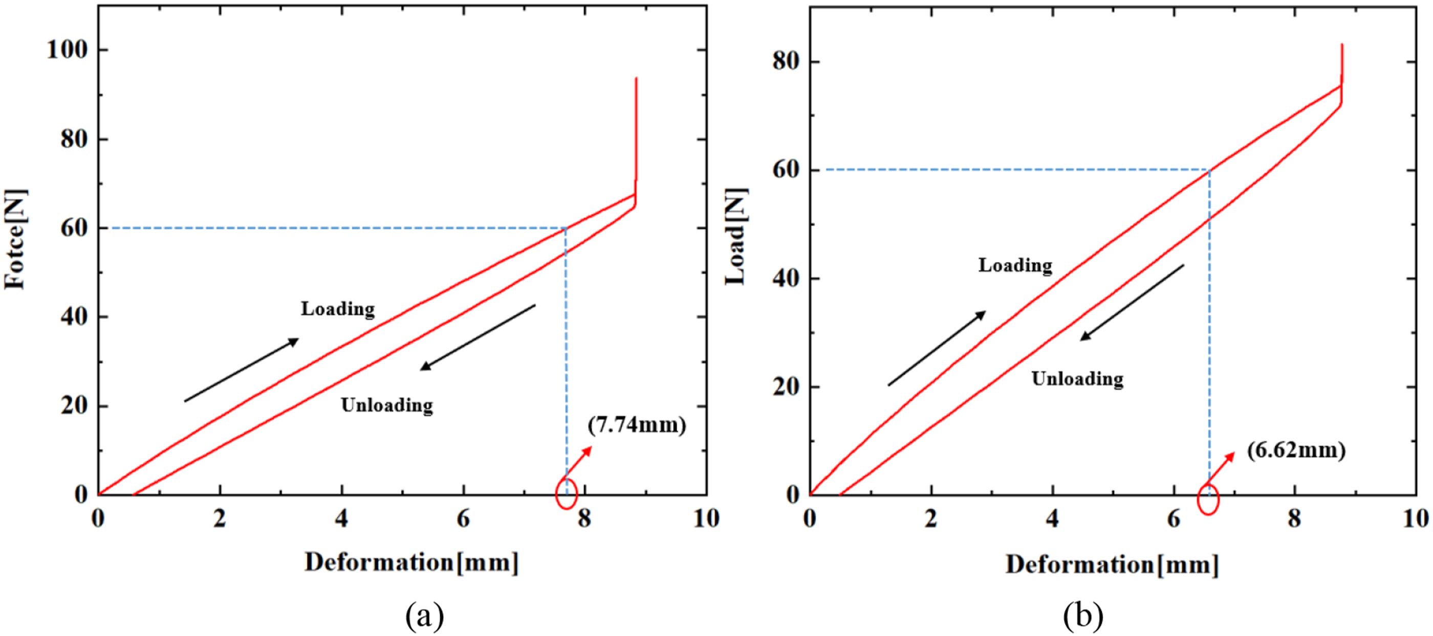
It can be observed that an elliptical loop forms during the loading-unloading cycles. This loop reflects the hysteresis behavior of the rubber material, which is caused by internal friction and viscoelasticity, leading to energy dissipation. The deformations of the rubber vibration isolator A and B under the related load 600 N are 7.74 mm and 6.62 mm, respectively. It is noteworthy that an irregular straight line appears at the end of the elliptical curve formed by the loading and unloading tests. This is due to the fact that the deformation at that point is so large that the isolator finally hits the bottom of the test platform. Consequently, despite the continued increase in load, the deformation of the isolator remains unchanged. However, this does not affect the final test results, as the applied load at this point is already 1.25 times the rated load.
Experiments on dynamic characteristics of rubber vibration isolators
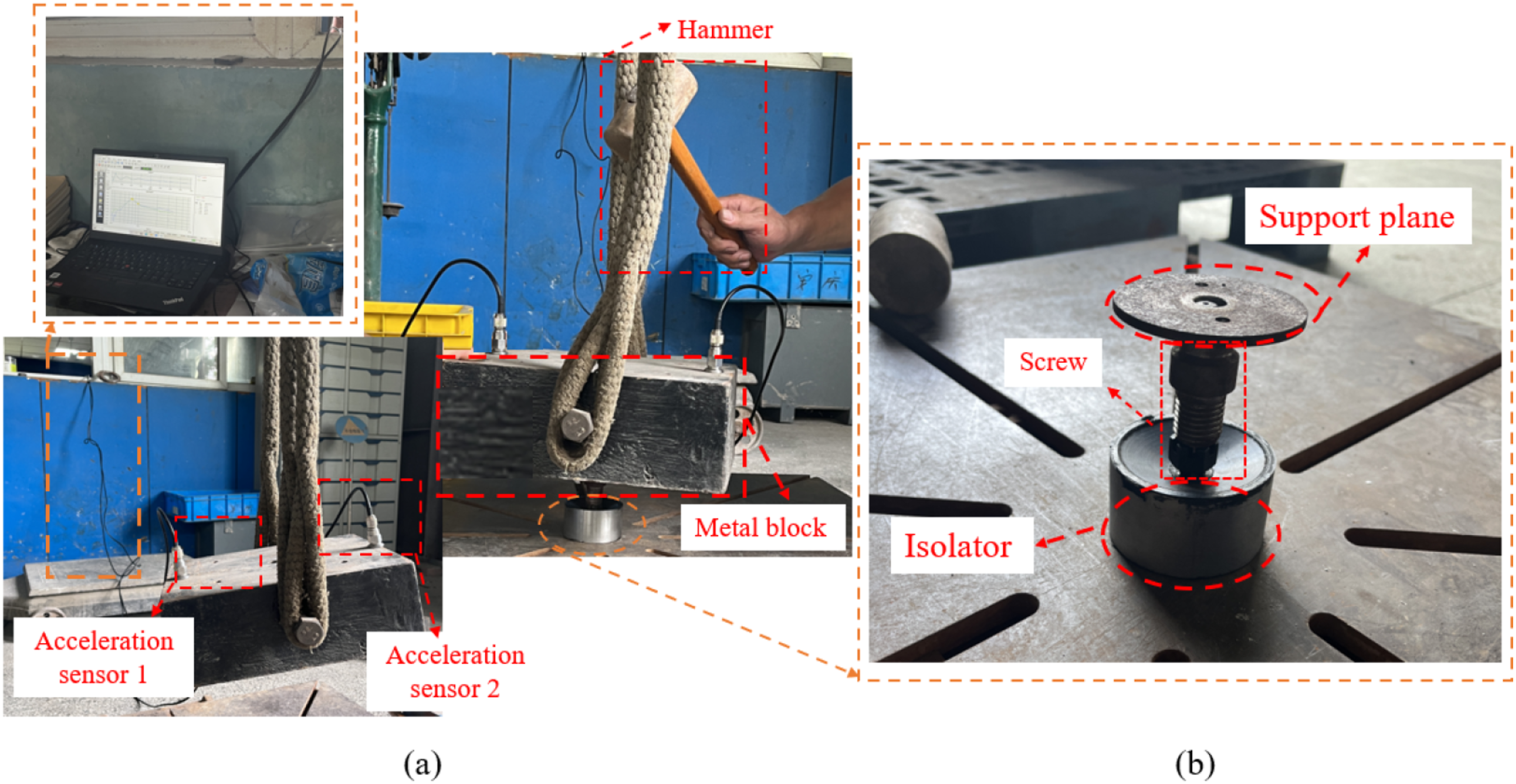
The dynamic performance of the rubber isolator A is experimentally obtained using the free-vibration decay method. The setup for this test, as shown in Figure 4, involves placing a 60 kg metal block on top of the isolator to simulate the rated operational load. A screw is added to the center of the inner ring of the rubber isolator, with a support plane added above it. In this case, the force can be applied to the isolator through the support plane and the connected screw, as shown in Figure 4(b). The block applies a compressive force to the isolator, resulting in a deformation of 7.74 mm, which is considerably larger than the typical deformation of rubber isolators (normally less than 3 mm). Two acceleration sensors, mounted on the metal block and connected to a data acquisition system, record the vibration response of isolator. These sensors ensure that the measured acceleration values are consistent, free from local measurement errors, and can accurately represent the dynamic behavior of the isolator. Broadband excitation is generated as the input force signal by manually hammering the metal block with a hammer, causing the system to undergo free vibration. The resulting vibration is captured in the time domain through the free-vibration decay curve and is analyzed using the power spectral density (PSD) curve to identify how vibration energy is distributed across frequencies. The PSD curve was chosen over FFT to reduce noise and provide a clearer view of the frequency domain behavior, making it easier to pinpoint the resonant frequency of the system. Based on the relationship described in equation (15), the resonant frequency Rubber vibration isolator dynamic stiffness test setup (a) overall view; (b) zoomed-in view.

From the free-vibration decay curve and the PSD curve presented in Figure 5, the tested dynamic stiffness and resonant frequency of isolator A is determined to be K
d
= 136.82 N/mm and f
v
= 7.6 Hz. The tested free-vibration decay curve (a) and power spectral density curve (b) of rubber vibration isolator A.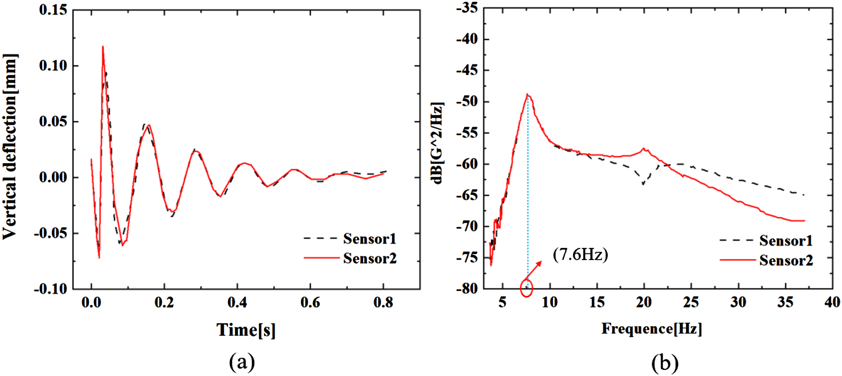
The Elliptic Method
44
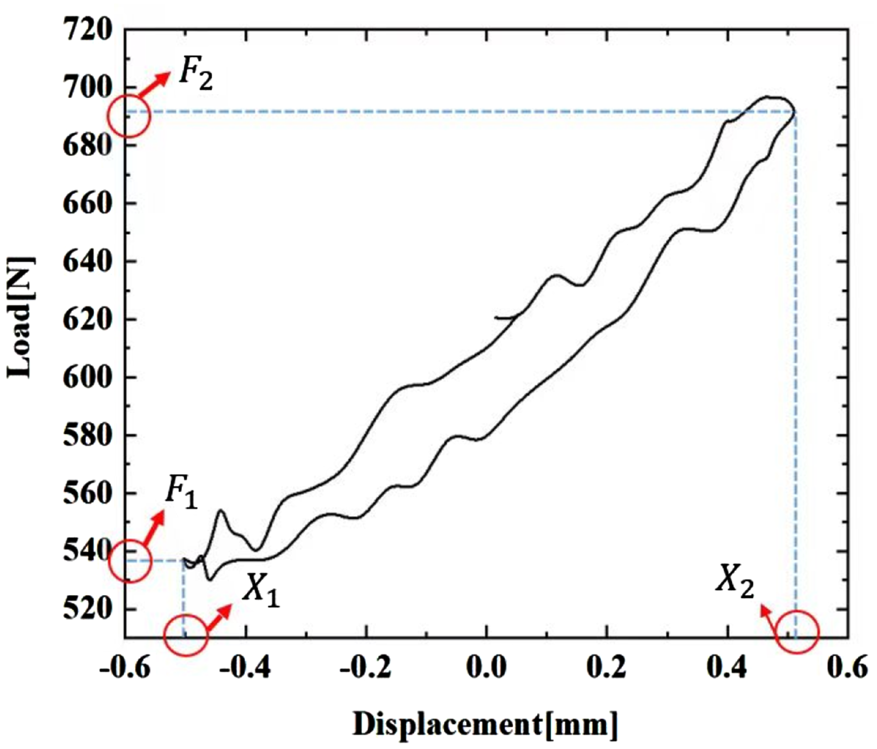
is used to assess the dynamic performance of rubber isolator B. This method determines dynamic stiffness by analyzing the force-displacement hysteresis loop generated during dynamic testing. The hysteresis loop forms an elliptical shape under cyclic forces, illustrating the relationship between applied force and resulting displacement. The area enclosed by the loop indicates energy dissipation caused by internal material damping. As shown in Figure 6, the rubber isolator is placed flat on the test stand. A screw is affixed to the center of the inner ring of the rubber isolator. According to ICS 17.160, a sinusoidal displacement load, Elliptic method test setup (a) overall view and (b) zoomed-in view. Isolator force-displacement curve.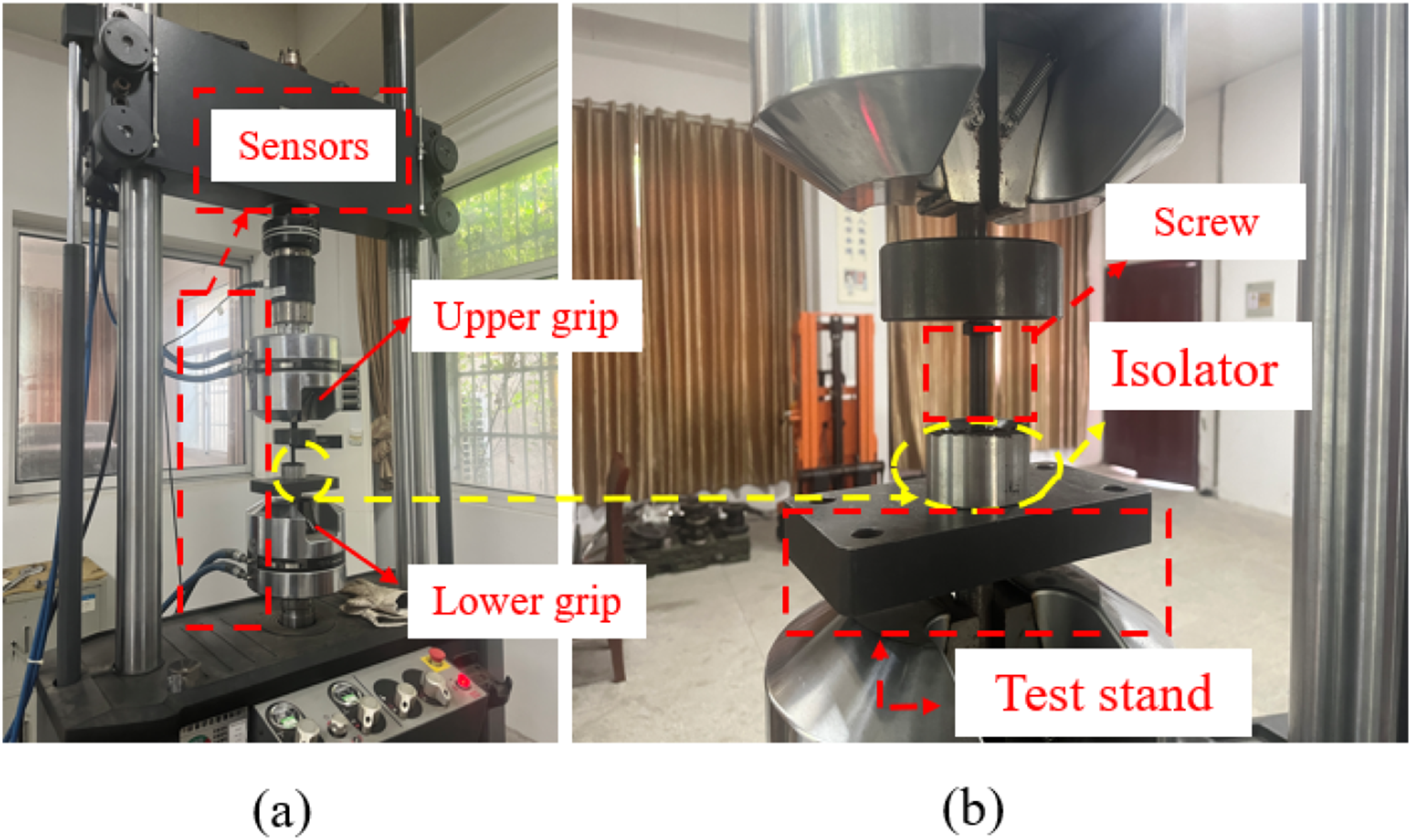
Uniaxial tensile test for rubber material
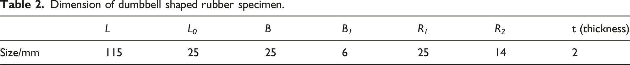
The material constants in the strain energy density function determine the mechanical property of rubber. These constants are typically derived from curve fitting of experimentally obtained stress-strain data through compression, shear or tensile tests of rubber material. Since the costs of the first two tests are much higher than the last one, tensile tests are commonly used in engineering to determine the mechanical properties of rubber materials. In the present work, uniaxial tensile test for rubber materials based on ICS 83.060 (Rubber, vulcanized or thermoplastic-Determination of tensile stress-strain properties) is carried out. As shown in Figure 8, the test sample is made into dumbbell shape with a length of 115 mm and a thickness of 2 mm. Detailed dimension information of the rubber specimen can be found in Table 2. Dumbbell shaped rubber specimen. Dimension of dumbbell shaped rubber specimen.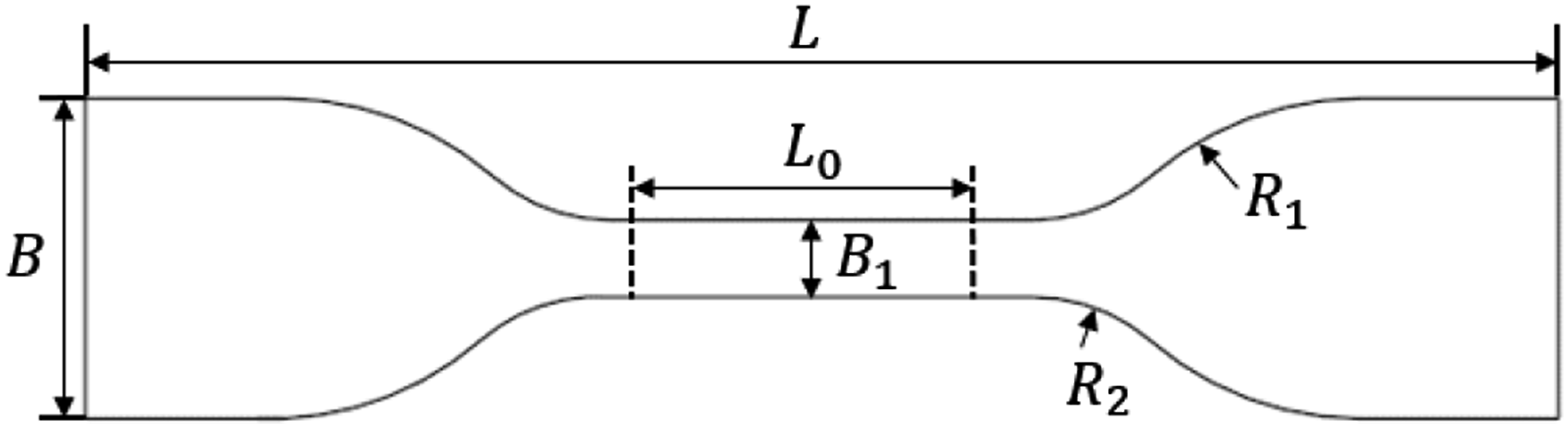
The test setup is depicted in Figure 9. The servo control desktop tensile testing machine AI-3000 of GOTECH TESTING MACHINES INNC (Dongguan) was employed for the rubber tensile test. Two ends of the rubber specimen are fixed by fixture 1 and 2. In the middle of the test sample, fixture 3 and 4, separated by the distance L0, which represents the effective experimental length of the specimen, are used to clamp the sample. During the test, fixture 1 is designed to move at a speed of 500 mm/min to apply the tension force on the rubber specimen. Rubber tensile testing set-up.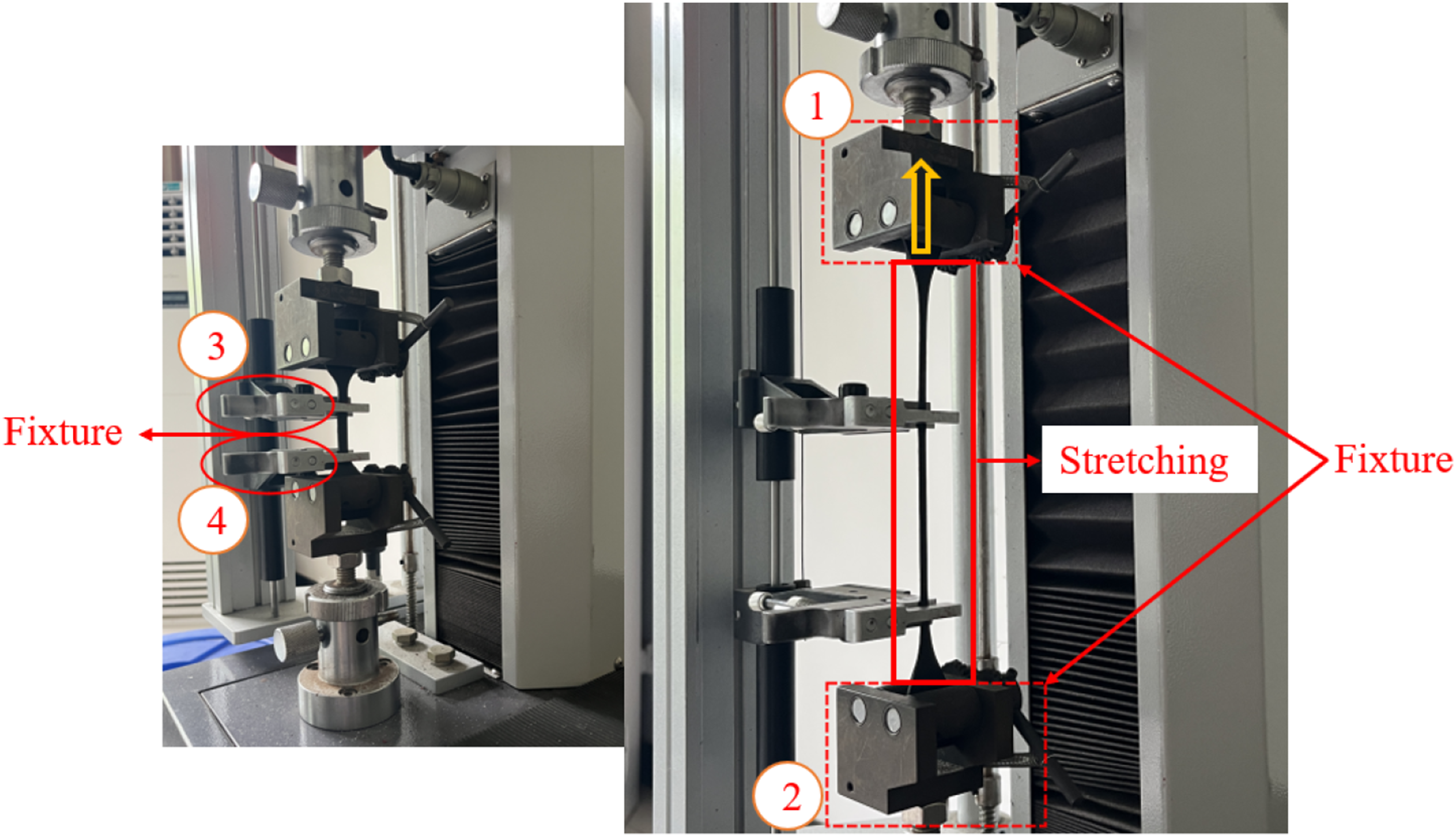
The experimentally obtained load-displacement data of the test samples are presented in Figure 10: Test rubber load-displacement data (a) 52 HA and (b) 54 HA.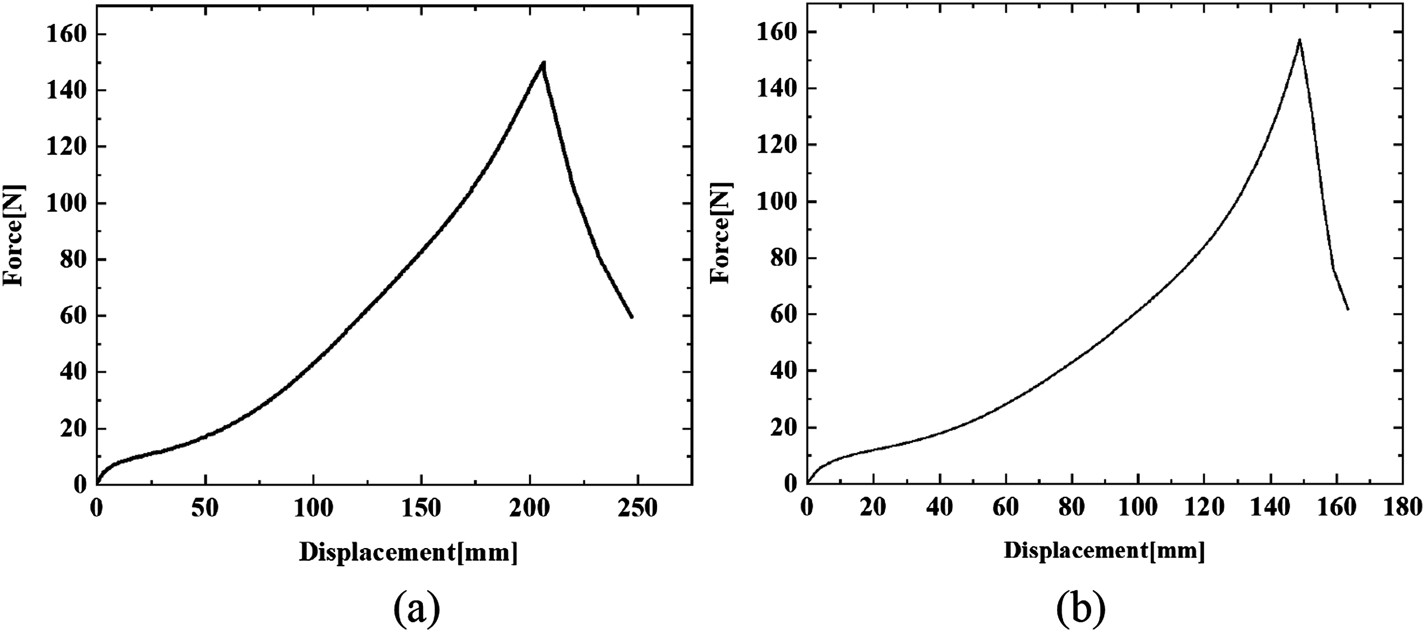
As can be seen from Figure 10(a), at the beginning of the testing, commencing from 0 N to 48.98 N, the curve exhibits a quite different trend from its overall performance. The upward trend observed in this stage is attributed to the presence of a slight sliding or gap between the specimen end and the gripper. Subsequently, the uniaxial tensile test curve of the rubber material exhibits three principal phases: a linear phase, an elastic phase, and a destructive phase. In the linear phase (roughly starting from 48.98 N to 79.62 N), the tensile force is linearly related to the deformation, and the slope of the curve in this phase is called Young’s modulus. From 79.62 N to146.9 N, the rubber is in the elastic phase, where the tensile force and the rubber deformation are no longer linearly related, but show a nonlinear elastic behavior. This phase is characterized by a gradual increase in tensile force with increasing deformation, the slope of which is known as the modulus of elasticity. Upon reaching a certain tensile force of approximately 147 N, the rubber material enters a destructive stage. The applied force on the sample drops sharply with the slow increase of the deformation, ultimately leading to the destruction of the rubber. It should be noted that the test data at the initial and end stages should be omitted when determining rubber material constants.
Next, the experimentally obtained load-displacement data need to be converted into engineering stress-strain data, as the aforementioned material constants are typically derived from curve fitting of the latter one. This transformation can be accomplished through the application of the relations Rubber tensile test stress-strain curves (a) 52 HA and (b) 54 HA.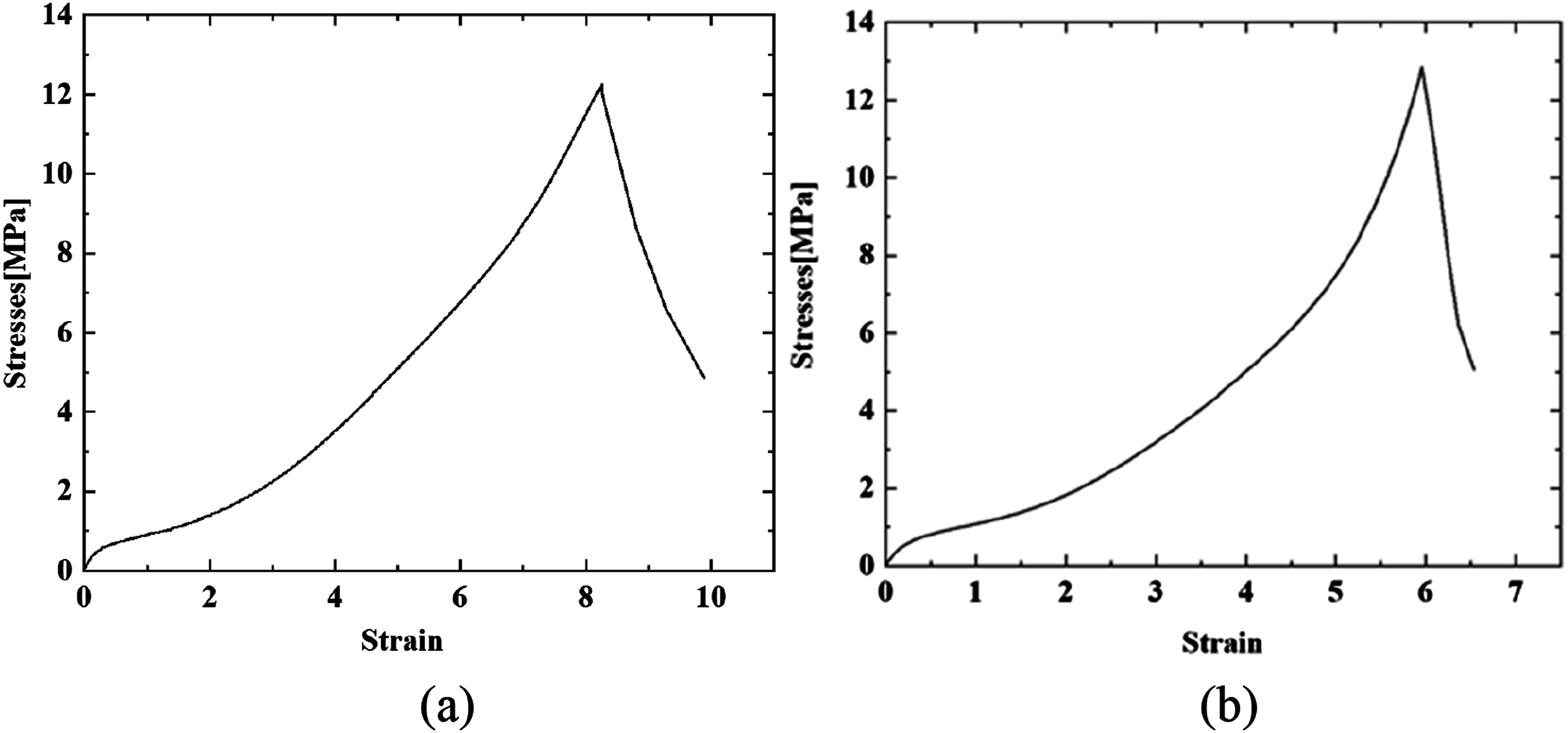
Modelling of rubber vibration isolator
The Finite Element Method (FEM) is adopted to assess both the static and dynamic behavior of the rubber isolator by utilizing commercial software, Ansys. While a linear model is proposed to predict the dynamic behavior of the isolator, a nonlinear isolator static model is necessary due to that the design of rubber isolator under large deformation exhibiting nonlinear feature is considered in current research.
In real-world applications, multi-directional coupling can influence the dynamic behavior of the isolator. In this study, vertical loads were the primary focus and it was assumed that rubber isolator operates predominantly in a vertically aligned system where the vertical displacement is dominant. As such, horizontal or angular displacement were not considered in our analysis.
Isolator nonlinear static model
Material properties
To appropriately capture the strong nonlinear properties of rubber material, it is essential to select a suitable hyperelastic model and determine the material constants in an accurate manner. In our work, the Yeoh third-order model was selected as the rubber hyperelastic model. The material constants of this model were obtained by fitting the stress-strain data obtained from uniaxial tension test using the least-squares method.
Through curve fitting the uniaxial tensile test data of rubber material presented in Figure 11, the material constants of the Yeoh third-order model for rubber with the hardness of 52 HA are C10 = 0.284;C20 = −1.331e-3;C30 = 2.426e-5, for rubber with the hardness of 54 HA, they are C10 = 0.425;C20 = −0.522e-3;C30 = 1.698e-4. The comparisons of the mechanical property of the rubber between predicted results through equation (13) and uniaxial tensile test data are shown in Figure 12. It can be seen that two sets of data agree well with each other, and the validity of the selection of Yeoh third-order model is confirmed. Comparison between test and Yeoh model (a) 52 HA and (b) 54 HA.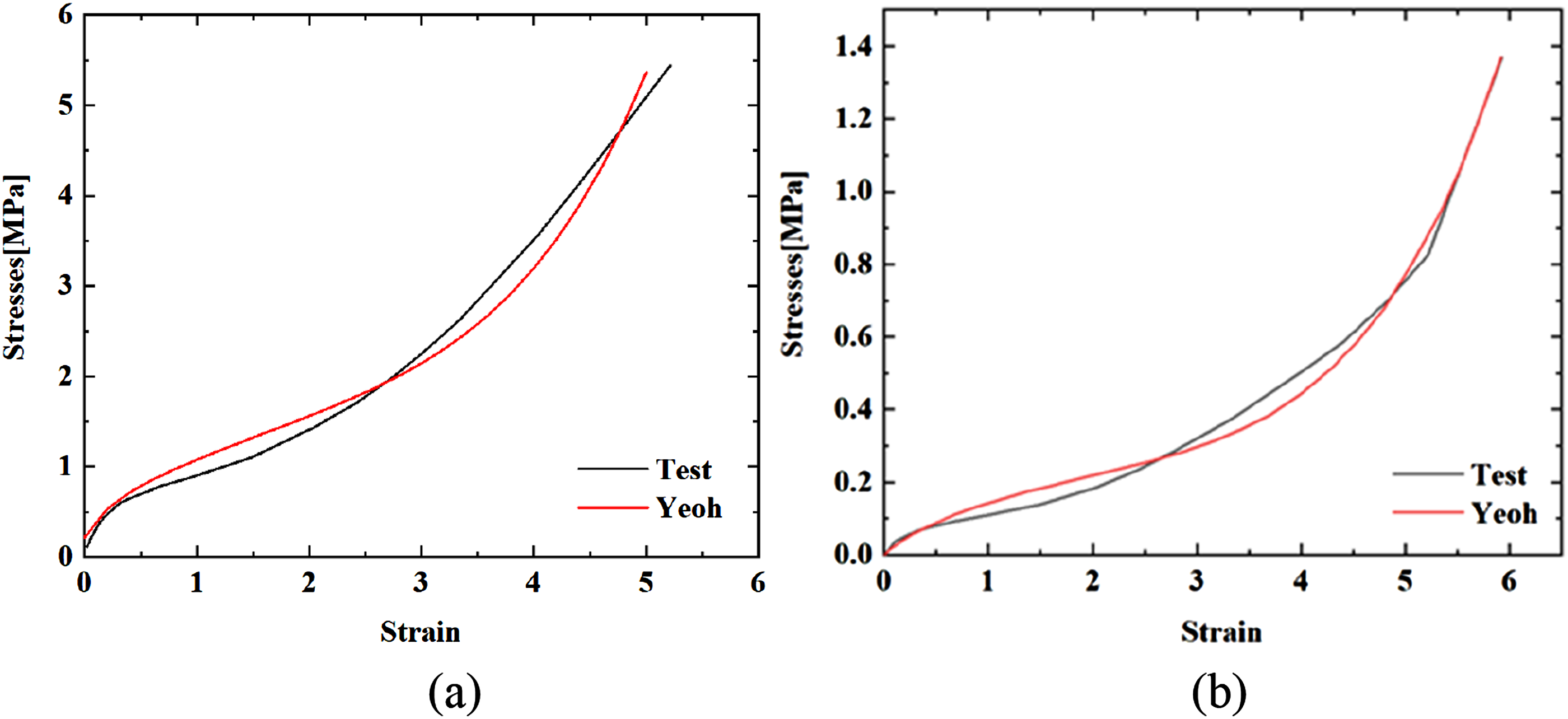
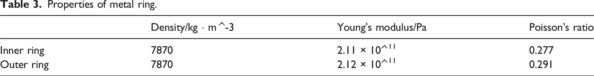
Properties of metal ring.
Boundary conditions
In the nonlinear static model, the inner and outer metal rings are bonded to the rubber. A fixed support is applied to the bottom of the outer metal ring. To simulate the state of the rubber vibration isolator under a 60 kg load, a vertical load of 600 N is applied on the upper surface of the inner metal ring in the vertical downward direction. The applied boundary conditions in the rubber isolator static model are shown in Figure 13. Boundary conditions.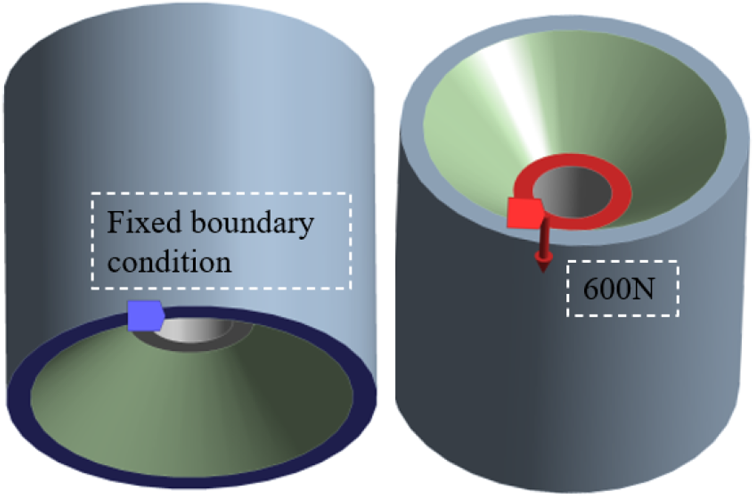
Isolator linear dynamic model
The prediction of the resonant frequency of rubber vibration isolators requires the determination of the dynamic elastic modulus of the rubber material, E
d
. Appropriately determining this value is key to predicting the dynamic characteristics of rubber vibration isolators. The relationship among E
d
, the DSR of the rubber
The static elastic behavior of rubber cannot be determined simply in terms of Young’s modulus.
45
In this study, the linear and elastic portions of the rubber stress-strain curves in Figure 11 are used to determine the static elastic modulus of rubber material, as shown in Figure 14. The static elastic modulus of 52 HA and 54 HA rubber, approximated from the slope of these two curves, are 1.78 MPa and 2.10 MPa. After conducting the static and dynamic tests on two randomly selected isolators with rubber material having hardness of 52 HA and 54 HA in advance, the DSRs of 52 HA and 54 HA rubbers are determined as 1.62 and 1.89, respectively. Using the aforementioned relationship between DSR of rubber and isolator, the dynamic elastic modulus of these two rubber material used in the dynamic model is calculated to be 2.88 MPa and 3.97 MPa. Intercepted uniaxial tensile stress-strain curve of rubber (a) 52 HA and (b) 54 HA.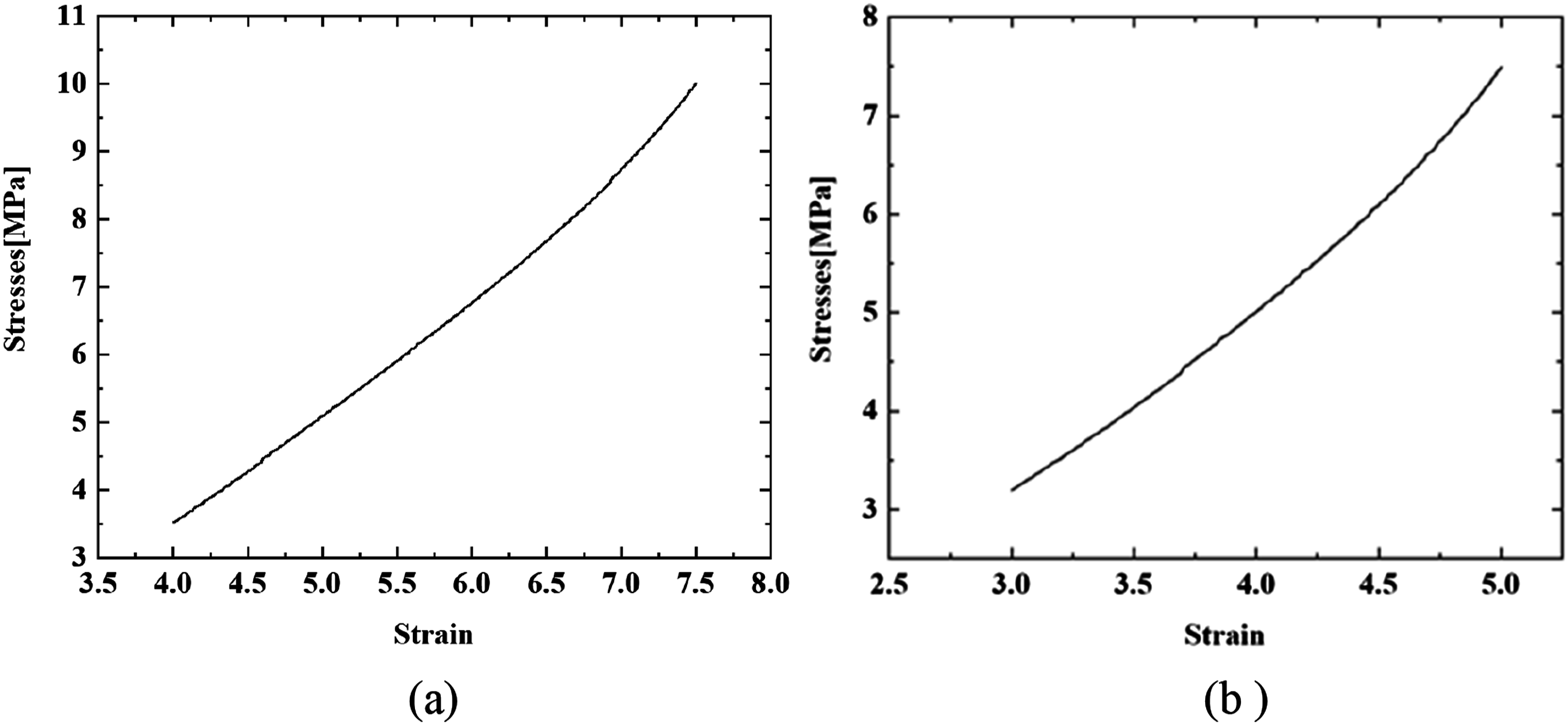
The linear dynamic behavior prediction model of the rubber isolator is illustrated in Figure 15. A cylinder is added to the center of the inner ring of the rubber isolator to serve as a support body, above which a 60 kg metal block is added. The isolator, the cylindrical support and the metal block are bonded together as a unified structure. Fixed support is applied to the bottom of the outer metal ring. In this instance, the mass load can be applied to the inner ring of the isolator via the cylinder. Both the metal block and the cylindrical support have a density of 7800 kg/m^3, a Young’s modulus of 1.22 × 10^11 Pa and a Poisson’s ratio of 0.25. The natural frequency of the isolator under a specific mass load can be determined through modal analysis using this linear dynamic model. Rubber isolator linear dynamic behavior prediction model.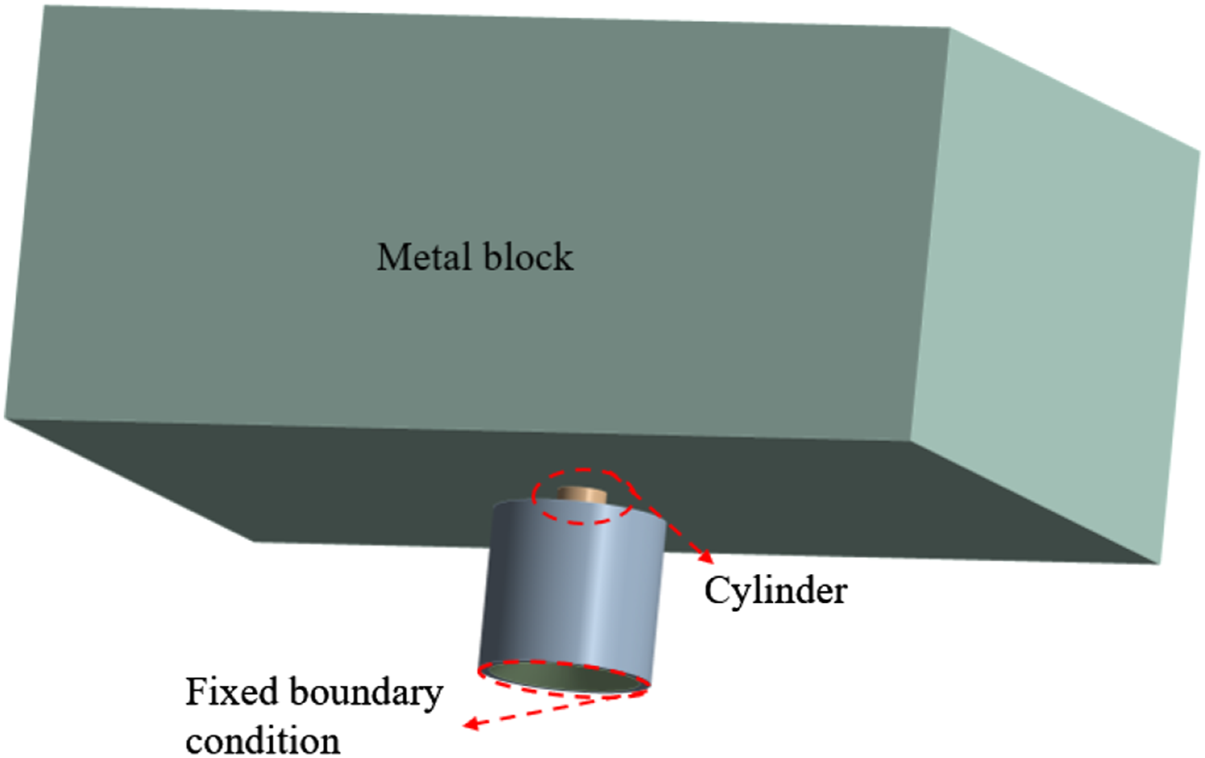
Design of rubber vibration isolator
Influence of geometry parameters
In order to obtain a vibration isolator with both sufficient load-carrying capacity and low-frequency vibration isolation performance, the structure of the isolator must be meticulously designed. Next, the influence of structure parameters on the performance of the rubber isolator are first investigated to provide guidance for the optimization design. The geometry parameters of the rubber vibration isolator under consideration include the height ( Geometric parameters correlation diagram.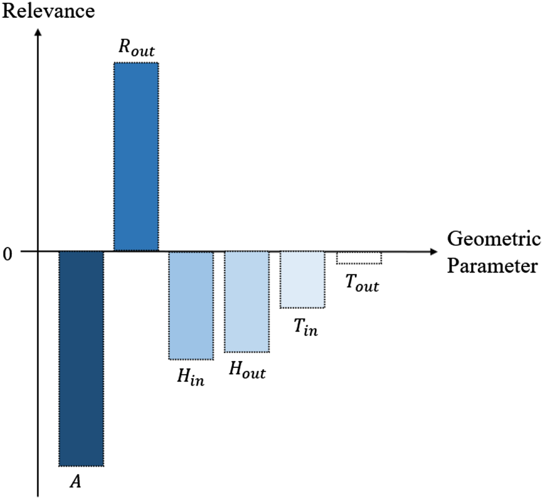
Figure 16 illustrates that the effects of the parameters on the static deformation of the vibration isolator are not always positively correlated. The parameters, in descending order of effect, are angle (
When performing the optimization design, to save the computation cost, the first few parameters with greater impact would be selected rather than the selection of all related parameters. However, when the rubber isolator is applied to the power systems in ship, the allowed installation space is often too limited; the related geometrical parameters always need to be all included in the design procedure to ensure that the enough load-bearing capacity and the required low-frequency vibration isolation performance can be simultaneously achieved. However, the above analysis can guide further adjustments on the optimized rubber geometrical parameters to meet the manufacturing requirement.
Optimization
The structural optimization of the rubber vibration isolator involves the optimization of several output parameters with multiple objective functions. Consequently, the global Multi-Objective Genetic Algorithm (MOGA) is selected for structural optimization due to its ability to simultaneously optimize multiple conflicting objectives, which is critical for improving the performance of the isolator while maintaining structural stability and load-carrying capacity.
Multi-objective optimization framework
In general, a multi-objective optimization problem can be thought of as seeking to maximize or minimize two or more different objective functions under certain constraints.46,47 This can be mathematically expressed as follows:
Design objectives and challenges
The lower the resonant frequency is, the broader the vibration isolation frequency band of the isolator. Nevertheless, a reduction in the resonant frequency typically results in larger deformations, which may potentially compromise the stability and load-carrying capacity of the isolator. To guarantee the generalization of the isolator design and to ensure that the optimized isolator can achieve optimal low-frequency vibration isolation performance and load-carrying capacity with necessary stability, in the design procedure, the isolator should be optimized to have the lowest resonant frequency and minimum deformation, while ensuring neither exceeds the maximum allowed value. Therefore, the static deformation and the resonant frequency of the rubber isolator are both chosen as the objective functions.
Design variables and constraints
The structural optimization is carried out by adjusting the geometrical dimensions of the rubber vibration isolator including
Find S (
Min
Min
s.t
The application of a vibration isolator to the power system of a ship is constraint by the very compact and limited installation space. In our work, the constraint conditions on isolator geometrical dimensions are set as
Find S (
Min
Min
s.t
Optimization procedure using MOGA
The MOGA optimization process is implemented using commercial finite element software, namely, ANSYS. MOGA operates by simulating the process of natural selection in order to explore a wide range of design solutions and to make iterative improvements upon them. The key stages of the optimization process shown in Figure 17 are as follows: Design procedure of the MOGA.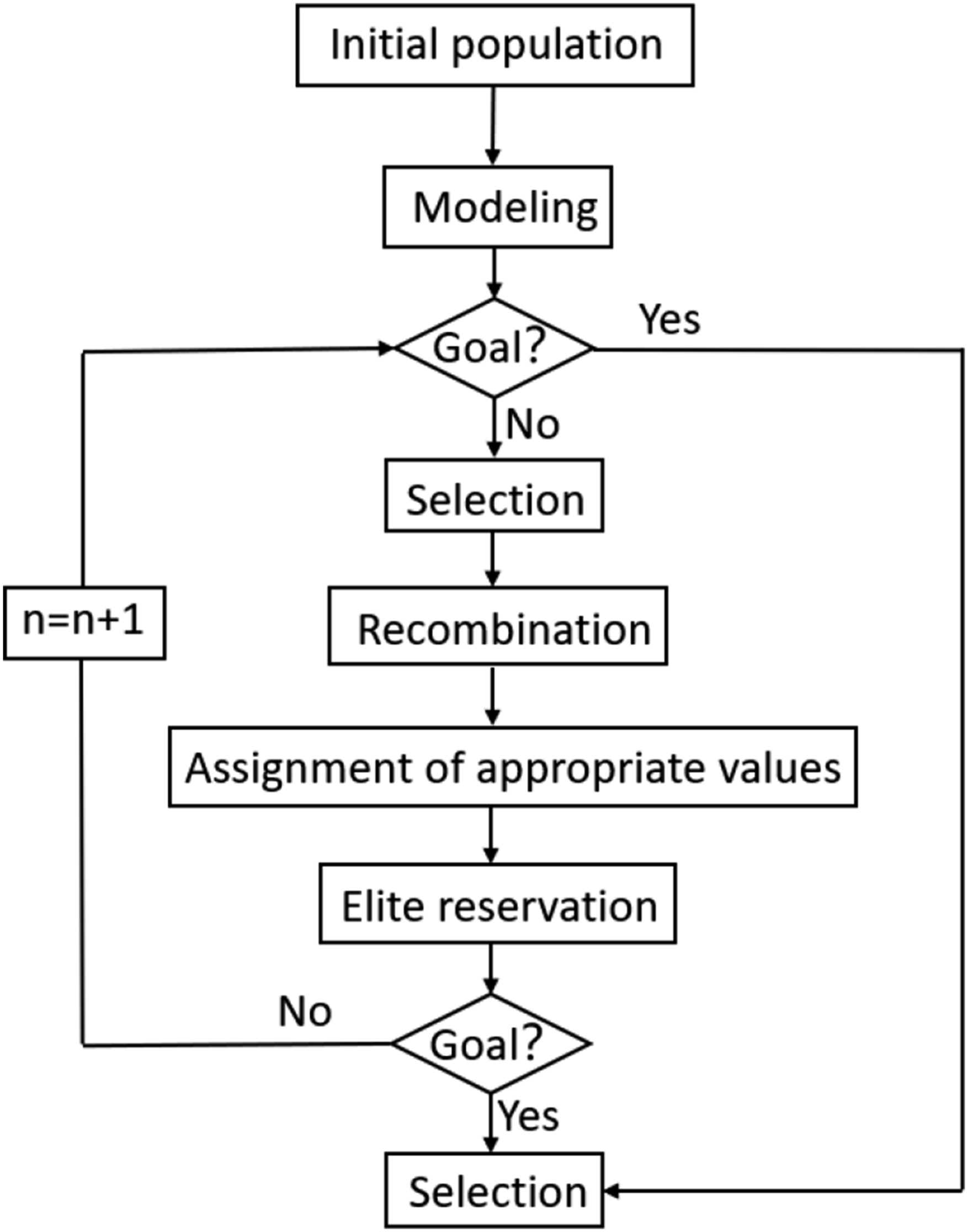
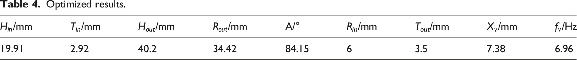
Optimized results.
Validation
Comparisons between predicted and tested results for isolator A.
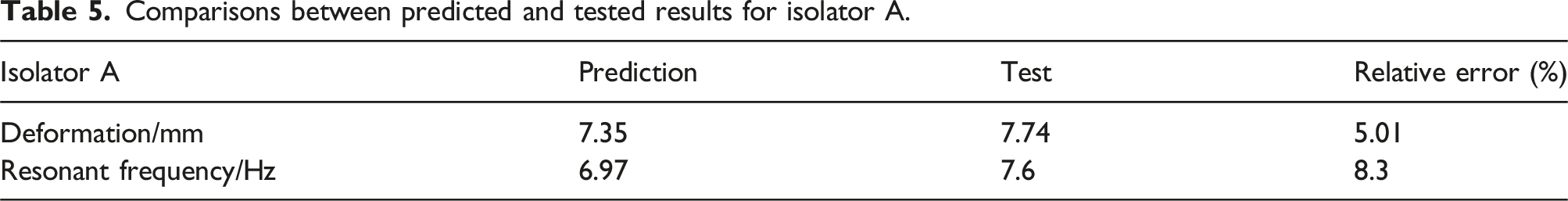
Several factors can contribute to the discrepancy in resonant frequency: small deviations in material properties and dimensions, differences between idealized and actual boundary conditions, and the possibility that real-world rubber exhibits nonlinearities not fully captured by the Yeoh model. Despite these factors, the relative errors between the predicted and tested results are within acceptable limits for engineering design purposes. The minor discrepancy observed between numerical and experimental results can well confirm the validity of the numerical prediction model. Furthermore, the above analysis demonstrates that the proposed design strategy can be employed to successfully design a rubber isolator meeting both load-bearing capacity and low-frequency vibration isolation performance requirements.
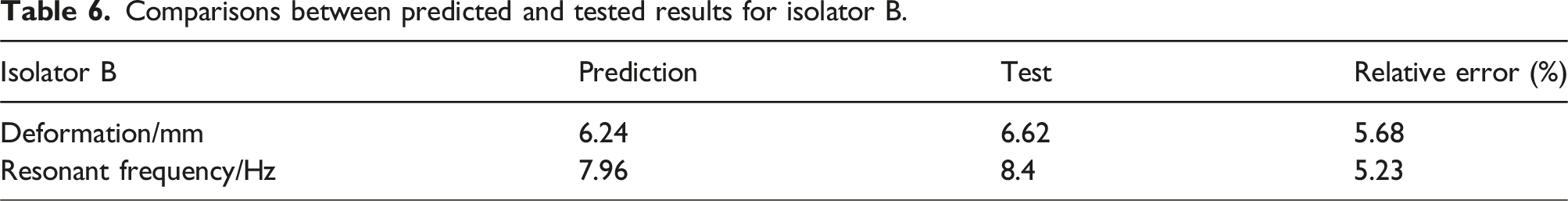
Comparisons between predicted and tested results for isolator B.
It is worthy to note that damping, primary performance parameters of rubber isolators, has a significant impact on their mechanical performance. According to ICS 17.200.10 (Standard for design of engineering vibration isolation), a damping ratio between 0.07 and 0.10 is considered optimal for rubber isolators, offering the best vibration reduction performance. The damping factor of the optimized rubber isolator can be determined by using the displacement amplitudes from Figure 5 and the formula
Conclusions
This paper presents a comprehensive numerical and experimental investigation into the design of rubber vibration isolators that meet both low-frequency vibration isolation and high load-bearing capacity requirements. The conclusions and major contributions of this work to the field of vibration isolation design are as follows: 1. The Yeoh model, combined with uniaxial tensile test of rubber material, can predict the static behavior of the rubber isolator under large deformation with strong nonlinear characteristics. 2. Through detailed parameter sensitivity analysis, this work identifies the influence of geometric parameters on both the static and dynamic performance of rubber isolators. These insights are valuable for design optimization, guiding engineers in making informed decisions to balance vibration isolation and load-bearing capacity. 3. The study establishes robust prediction models for the assessment of rubber isolator static and dynamic behavior under large deformation. In conjunction with the Multi-Objective Genetic Algorithm (MOGA), a design strategy that is capable of effectively balancing the dual requirements of low-frequency isolation and high load-bearing capacity is proposed. This approach is especially beneficial in applications, where both factors are crucial and difficult to optimize simultaneously. Furthermore, the strategy offers a practical framework suitable for real-world engineering design. 4. The conducted experiments well confirmed that the rubber vibration isolator, which can meet the requirements both on load-bearing capacity and low-frequency vibration isolation, can be successfully designed by employing the proposed design strategy.
The findings presented herein provide engineers and researchers with a more holistic framework for the design of rubber isolators, thereby advancing current knowledge in vibration isolation design. The proposed design strategy not only ensures practical applicability in engineering but also offers a valuable reference for future research in optimizing isolators for nonlinear and large deformation conditions.
Footnotes
Declaration of conflicting interests
The author(s) declared no potential conflicts of interest with respect to the research, authorship, and/or publication of this article.
Funding
The author(s) disclosed receipt of the following financial support for the research, authorship, and/or publication of this article: The research reported here was supported by Nature Science Foundation of Hubei Province (2022CFB847) and China Scholarship Council (202306950060).