
Abstract
It has always been a challenge to develop low-frequency anechoic coatings under high hydrostatic pressure. Based on active pressure balancing strategy (APBS), the airbag embedding in Helmholtz resonator model is proposed to achieve low-frequency and broadband sound absorption under high hydrostatic pressure. Compared with some existing pressure resistance schemes, the proposed anechoic coating has a thinner and lighter structure, lower sound absorption frequency band, and can withstand higher pressure. The proposed anechoic coating achieves sound absorption coefficient larger than 0.5 within the bandwidth of 24.5∼1000 Hz under pressure of 0.1 MPa, and within the bandwidth of 73.6∼1000 Hz under pressure of 5 MPa. The thickness of 10 mm is less than 1‰ of the incident wavelength at 100 Hz. The proposed model provides a new solution to the problem of improving low-frequency sound absorption performance of the anechoic coating under high hydrostatic pressure.
Introduction
Underwater acoustics are crucial in various fields such as detection, underwater communication, and fishing. Low-frequency sound waves are highly preferred in these fields owing to its less attenuation during propagation. However, exposure to low-frequency noise, especially infrasound, can have many adverse effects on organisms. For example, it can negatively impact the human body’s nervous system and blood circulation. 1 Traditional acoustic materials and structures have limited capabilities in achieving low-frequency and broadband sound absorption. To address this challenge, various solutions have been proposed, such as viscoelastic or composite structure coatings,2–15 Helmholtz resonators,16–20 micro-perforated plates,21–26 local resonance structures,27–42 and porous materials.43–46 An impedance-matched composite demonstrates high absorption in the 4∼20 kHz frequency range. The structure comprises tungsten oscillators and polyurethane connection, but its overall thickness is less than 9 mm. 4 The underwater anechoic coating with horn-shaped holes has achieved effective sound absorption performance in 3∼10 kHz range, which is still effective under oblique incidence conditions. 47 A 50 mm thick quasi-Helmholtz resonance enables tunable low-frequency and broadband perfect absorption in 300∼1000 Hz range. A thin tube was extended into the Helmholtz resonator, and the wall was covered by viscoelastic rubber to improve energy dissipation. 16 A composite structure was proposed with a micro-perforated aluminum panels mixed with rubber, which possesses low-frequency (<1 kHz) underwater sound absorption with omnidirectional and large absorption coefficient. The 33 mm thick anechoic coating enables broadband sound absorption from 125 to 900 Hz. 17 A coiled water channel was constructed to extend the length of the Helmholtz resonator, by winding it into a spiral shape, and covering it with a layer of viscoelastic rubber on the wall. The 2.3 mm thick anechoic coating reaches an absorption coefficient over 0.5 around 145∼165 Hz due to the dissipative slow sound is generated by the channel. 19 The 75 mm thick panel composed of 11 micro-perforated units achieves an average absorption coefficient of 80% in 1.3∼3.1 kHz range. 21 The introduction of microporous plates and high-viscosity castor oil improves the absorption coefficient and expands the absorption band from 1 kHz to 15 kHz. 25 The 60 mm thick meta-absorber was proposed via embedding thin and thickness-graded circular elastic plates into an elastomer matrix, which has a good underwater sound absorption capacity (USAC) from 300 to 1000 Hz. 27 The underwater meta-structure was constructed by perforating a helix metal into viscoelastic damping rubber with effective acoustic absorption frequency below 1 kHz. 34 The 210 mm thick meta-structure is composed of a cylindrical cavity, a rubber matrix, and two tungsten disks, which demonstrates an excellent sound absorption effect from 21 to 300 Hz. 36 In an experiment, the 34 mm thick coating achieves good absorption performance in the range of 0.5∼3 kHz, which is composed of two different layers containing steel local resonators. 37 The porous aluminum anechoic coating under specific parameters achieves good sound absorption performance within 5∼30 kHz. 43 Compared to perforated panels, porous metal absorber owns a better USAC, and the thickness of the entire structure by at least 80% is reduced due to the filling of the viscous fluid. 44 As is well known, when underwater, objects are subjected to hydrostatic pressure, which is proportional to the water depth at which the object is located. For example, at a water depth of about 103 m, the hydrostatic pressure will reach 10 atm. However, for the anechoic coating operating under high hydrostatic pressure, it is still a challenge to improve its low-frequency and broadband USAC.
Different scholars have defined different thresholds for high hydrostatic pressure, such as 0.8 MPa 48 1.5 MPa, 49 and 2.5 MPa. 39 In the field of physics, 1 MPa is already considered high pressure in gas studies, whereas pressures above 10 MPa are generally regarded as high pressure in liquid studies. Typically, water depths less than 100 m are classified as shallow water, and depths greater than 300 m as deep water. For common materials like rubber, the modulus typically ranges around 2∼10 MPa. In engineering applications, it can be considered high pressure when the ratio of pressure load to material modulus reaches between 0.8 and 1.2. From the perspective of material performance, a pressure that causes a strain of over 10% in the material can also be considered high pressure. Here 1 MPa is set as the threshold for high hydrostatic pressure.
Some scholars have successfully designed and conducted experiments on the anechoic coating for high hydrostatic pressure. For instance, a non-resonant absorber has been developed that can overcome high hydrostatic pressure and provides effective echo reduction over 15 dB in 0.5∼15 kHz frequency range. Broadband absorption is achieved through judicious choice of matrix material and fillers. 2 The hybridization of one- and two-dimensional nano-carbon materials provides a new approach to improve underwater sound absorption under high hydrostatic pressure. Compared with carbon nanotubes or graphene nanoplatelets, the equivalent nanocomposites mixed with these two materials have better sound absorption under 0.4∼1.0 MPa at the frequency of 1.5∼7 kHz. 8
A diverse strategy has been proposed to dissipate waterborne sound via a composite metasurface, in which frontend metal perfect match layer carries out efficient acoustic-elastic energy conversion while the backing layer with rubber-metal resonators eliminates the converted elastic vibrations. This coating achieves an average absorptance of 87.8% ranging from 760 to 920 Hz. 33 The location and bandwidth of resonant band gaps are affected by the interaction between the particle-filled polyurethane and the spiral resonator. This metamaterial structure achieves an average absorption coefficient of 0.54 in the range of 0.8∼6 kHz under a normal atmospheric pressure, and of 0.51 in the range of 1.5∼6 kHz under 0.5 MPa. 39 An acoustic metamaterial comprising 12 harmonic oscillators as multi-scatterers in each unit cell achieves better sound absorption under hydrostatic pressure compared to the pure viscoelastic polymer. Its average α reaches to 0.78 in the frequency range of 600∼2000 Hz under 0.5 MPa. 49 A 20.25 mm thick honeycomb-type acoustic metamaterial composed of rubber-steel-rubber plate achieves an average sound transmission loss of 10 dB in the 2∼10 kHz frequency range under the hydrostatic pressure of 3 MPa. 50
According to the research mentioned above, it is still challenging to achieve efficient USAC below 1000 Hz under high hydrostatic pressure conditions. Although the use of viscoelastic plates with fibers has improved the compressive performance of coatings, the USAC is still insufficient. Additionally, achieving efficient USAC under high pressure is crucial for anechoic coatings. These problems and challenges were identified a decade ago, yet to the best of our knowledge, a model with thin structure and efficient USAC has not been developed for both low-frequency and high hydrostatic pressure conditions.
High hydrostatic pressure leads to poor low-frequency sound absorption performance of the coating, including but not limited to the following reasons. As the hydrostatic pressure increases, the soft polyurethane rubber becomes harder. Accordingly, the sound speed of rubber increases, the wavelength at low frequencies also increases, so that it is much larger than the structural size.49–51 Rubber characteristics related to absorption are also influenced by the temperature of working environment52,53 and the aging processes of the rubber. 54 Furthermore, under high hydrostatic pressure, the compression of the anechoic coating, as well as changes in the shape and size of the cavity, weakens the sound absorption characteristics of the overall layer. 55
In this study, a novel ultra-thin anechoic coating model is proposed based on the active pressure balancing strategy (APBS), which actively maintains a balance between the internal pressure of the coating and the external hydrostatic pressure. Due to pressure balance, the shape and size of the cavities remain generally unchanged. This approach provides a new method for constructing a lightweight and thin anechoic coating with efficient USAC under high hydrostatic pressure. The proposed coating achieves a sound absorption coefficient α greater than 0.5 in the frequency range of 24.5∼1000 Hz under 0.1 MPa and 73.6∼1000 Hz under 5 MPa, with a thickness of only 10 mm. To the best of our knowledge, compared to existing anechoic coatings, the proposed model not only provides the lowest frequency and widest bandwidth, but also has the smallest thickness.
Anechoic coating models based on APBS
Material parameters of materials.
Viscoelastic rubber plate model
Figure 1(a) illustrates low-frequency USAC of two types of sound absorption structures attached to a steel backing. One type is a rubber plate without an air layer, while the other type is a rubber plate with an air layer inside. The line labeled “Plate without air layer” indicates that a 1 mm thick rubber plate has poor low-frequency USAC. To improve performance, a thin air layer is introduced between the rubber plate and the steel backing. In order to balance external pressure, the air pressure is then set to the hydrostatic pressure. The coating model of viscoelastic rubber plate with air layer. (a) Sound absorption coefficient versus frequency; (b) power dissipation density (Q: W/m3) at two peaks; and (c) deformation of the structure at two peaks. The rubber plate thickness is 1 mm. The air layer is thin but enough to keep the pressure, and to maintain the cavity top away from the steel backing.
The vertical axis indicates the sound absorption coefficient α, while the horizontal axis represents the frequency of the incident sound wave. Here, frequency of 1 Hz-1 kHz is focused. At a pressure of 0.1 MPa, the α exceeds 0.5 in the range of 32.5∼328.5 Hz, with a notable absorption peak occurring at 103.5 Hz, where the α reaches a value of 0.73. When the pressure increases to 0.2 MPa, the USAC decreases significantly especially below 400 Hz. While the pressure further increases to 1.0 MPa, the maximum α is 0.26 at 404.1 Hz. Under a high pressure of 5 MPa, the USAC is close to that of a plate without an air layer.
In order to explain how the pressure affects the USAC of the plate, Figure 1(b) and (c) are plotted to illustrate power dissipation density (PDD, Q, with unit of W/m3) and deformation of the rubber plate caused by the sound, respectively. Under different pressures, the distributions of dissipated power are similar, but the overall level decreases when the pressure increases from 0.1 to 1 MPa, as shown in Figure 1(b). The dissipated power of the plate is mainly distributed at both ends and in the middle of the upper and lower surfaces. Corresponding to Figure 1(b), the structural deformation (|
The sound absorption performance of the plate structure with air layer inside is highly sensitive to pressure. Moreover, the hydrostatic pressure has a significant negative effect on the performance of the acoustic coating. Effective sound absorption cannot be achieved under high pressure even though the air layer improves the low-frequency USAC of the rubber plate.
Helmholtz resonator model
A Helmholtz resonator has become a commonly used sound absorber owing to its perfect absorption. However, it is a challenge to achieve low-frequency and broadband sound absorption in ultra-thin structures. A spherical Helmholtz resonator model with 10 mm thick is analyzed. The resonator is filled with water and is fixed on the rigid steel backing, with the inner and outer water connected through a small hole. The α under different pressures is shown in Figure 2(a). Due to the limited thickness of the structure with only 10 mm, the USAC is poor with the maximum of the α only 0.11 within the low-frequency range below 1000 Hz. Additionally, the USAC of the structure does not vary significantly under different pressures. The PDD is further shown in Figure 2(b). Most of the dissipation power distributes in the solid region, with only a small portion around the orifice. However, the total amount of dissipation power remains insufficient to achieve effective low-frequency sound absorption under high hydrostatic pressure. The spherical Helmholtz resonator coating model. (a) Sound absorption coefficient versus frequency and (b) power dissipation density (Q: W/m3) at 1000 Hz. The thickness of rubber is 10 mm. The radius of the spherical cavity is 4.5 mm and the aperture is 0.4 mm.
Airbag model
As demonstrated in Figure 3, a spherical airbag coating model is proposed. The internal pressure of the airbag is adjusted to match the external hydrostatic pressure, and the USAC under different pressures is focused. The single airbag coating model. (a) Sound absorption coefficient versus frequency. (b) and (c) Power dissipation density and deformation (Q: W/m3) at two peaks. The black arrows represent the direction of deformation. The thickness of the coating is 10 mm. The radius of the spherical airbag is 4.5 mm.
Figure 3(a) shows that at a pressure of 0.1 MPa (approximately 1 atm), the value of α exceeds than 0.5 in the range of 36.5∼582.5 Hz, with a peak absorption at 143.5 Hz. When the pressure increases to 0.2 MPa, the USAC is nearly the same as that at 0.1 MPa, with only slight attenuation in the range of 10∼200 Hz. However, the USAC decreases as the pressure continues to increase. The PDD and deformation of the airbag at the absorption peak are illustrated in Figure 3(b) and (c). At 143.5 Hz under 0.1 MPa, the shell of the airbag deforms like a respiratory mode, the dissipation power is evenly distributed within the shell. As the pressure increases to 5.0 MPa, the absorption peak appears at 352.6 Hz. The airbag shifts up and down, while the deformation concentrates in the bottom fixing joint. As the pressure increases, the stiffness of airbag’s breathing deformation increases, and the corresponding natural frequency is greater than the translational modal frequency of airbag. Consequently, the overall PDD and α both decrease at high pressure, making it a challenge to achieve efficient USAC with a single airbag under high hydrostatic pressure.
Airbag embedding in Helmholtz resonator model
The anechoic coating of an airbag embedded in Helmholtz resonator model is illustrated in Figure 4. The spherical Helmholtz resonator is composed of a nozzle and a thin layer cavity outside the airbag, which is filled with water. The air pressure inside the airbag is maintained at the same level as the external hydrostatic pressure. The anechoic coating is typically composed of numerous unit cells arranged periodically, as shown in Figure 4(a). To simplify calculations, one unit cell is selected and simplified by an axisymmetric cell,
47
as shown in Figure 4(b). The cross-section is shown in Figure 4(c). The overall thickness of the structure H = 10 mm and its radius R = 5 mm are fixed in the calculation. The entire coating is attached to a steel backing. The bottom of steel is fixed. (a) Overall view of anechoic coating model and unit cell. (b) A unit cell with a cut plane. (c) Internal structure of anechoic coating at the cut plane. Total thickness of the anechoic coating H = 10 mm, and radius of the cell R = 5 mm. External radius of the spherical airbag is 4.5 mm, the same as it in Section 2.3; (d) Assemblies of system for active pressure balancing strategy.
As shown in Figure 4(d), the APBS system includes several components, such as two pressure sensors, a signal processor, two high pressure air tanks, a solenoid valve, and a compressor. External pressure (p w ) and air pressure (p a ) are detected by the pressure sensors in water and in the air pipeline, respectively. The pressure signals of water and air are transmitted to the signal processor. A small pressure (p v ) is introduced to prevent frequent switching of the solenoid valve. The solenoid valve has three working positions: (1) If p w > p a + p v , the solenoid valve connects the high-pressure gas tanks and the airbag. Thus, the airbag is inflated. (2) If p w < p a − p v , the solenoid valve connects the airbag and low-pressure gas compressor. So, the airbag is deflated. (3) Otherwise, the solenoid valve is normally closed. Accordingly, based on the pressure difference between hydrostatic pressure and airbag, the signal processor controls the action of the solenoid valve. The signal processor also controls the compressor to compress low-pressure gas into a high-pressure gas tank. This system maintains a balance between the pressure inside the airbag and the external hydrostatic pressure.
Investigate airbag embedding in Helmholtz resonator model
The USAC of the airbag embedding in Helmholtz resonator model is examined. The influence of structural and material parameters on the USAC is further investigated under different pressures.
USAC of the model
For the convenience of discussion, the sound absorption coefficient greater than 0.5 is defined as effective sound absorption, and the corresponding frequency range is called as effective sound absorption band. Figure 5(a) displays the USAC versus frequency of the anechoic coating under different pressures. At a pressure of 0.1 MPa, the effective sound absorption band is 35.5∼1000 Hz, with point A (35.5 Hz, 0.5) and point C (106.2 Hz, 0.9). Two maxima of α, 0.975 and 0.953, occur at 178 Hz and 692 Hz, respectively. Under a pressure of 1.0 MPa, the 0.5 and 0.9 of α correspond to frequencies of 53.5 Hz and 151.6 Hz, respectively. Two maxima occur at frequencies of 239 and 628 Hz, which are closer to each other than that under pressure 0.1 MPa. When the pressure increases to 5.0 MPa, the effective sound absorption band is from 152.5 (point B) to 1000 Hz, with a single absorption peak of 0.999 at 372 Hz. As the pressure increases from 0.1 MPa to 5.0 MPa, the effective sound absorption band of the anechoic coating decreases from 35.5 to 1000 Hz to 150.1∼1000 Hz. Comparing the sound absorption coefficient at 100 Hz for 0.1 MPa (point D) and 5.0 MPa (point E), α decreases from 0.88 to 0.33 as the pressure increases, where the reduction is 62.5%. Performance of the airbag embedding in Helmholtz resonator model. (a) USAC versus frequency under different hydrostatic pressures, where d = 0.1 mm, t = 0.4 mm, h = 0.5 mm are fixed. A (35.5 Hz, 0.5), B (150.1 Hz, 0.5), C (106.2 Hz, 0.9), D (100 Hz, 0.88), and E (100 Hz, 0.33); (b) to points D and E with a same frequency 100 Hz, deformation |u|, PDD in solid QS and fluid QL domains are compared between pressures of 0.1 MPa and 5.0 MPa; and (c) velocity |v|, PDD of QS and QL, at absorption peak frequencies under pressures 0.1 MPa and 5.0 MPa.
To analyze the reasons for the performance attenuation of the coating under high pressure, structural deformation and PDD at 100 Hz are compared in Figure 5(b). Compared with the deformation at 0.1 MPa, the maximum deformation at the top of the airbag under 5.0 MPa is smaller, with an attenuation about 40%, and the deformation of the surrounding rubber matrix is also significantly reduced. The reduction in deformation leads a decrease of PDD in both the solid (QS) and liquid (QL) domains. Under a pressure of 5.0 MPa, QS decreases by about 65% and QL at the orifice decreases by about 64.5% compared to values under 0.1 MPa. The mechanism behind can be explained as follows: High pressure increases the density of the air inside the airbag, reducing its compressibility and causing less deformation relate to the rubber matrix. This leads to a decrease in the flow velocity of the liquid passing through the orifice, ultimately results in a reduction of dissipation power in both the liquid and solid.
According to the first column of Figure 5(c), the first absorption peak under 0.1 MPa corresponds to 178 Hz, where the dissipation power in the anechoic coating is primarily distributed in the water domain around the orifice, as well as in the shell of the airbag. In other fields of rubber and water, PDD is almost zero. Similarly, the second absorption peak under 0.1 MPa locates at 692 Hz. Compared to the first absorption peak, the dissipation power of the second one increases in the rubber but decreases around the orifice, as shown in the second column of Figure 5(c). Absorption peak under a pressure of 5.0 MPa corresponds to a frequency of 372 Hz. Comparing 0.1 MPa and 5 MPa in the first and the last columns of Figure 5(c), the former has a larger PDD at the orifice, while the latter exhibits a larger PDD in the rubber matrix. Despite these differences, the overall power dissipation remains at a high level, with absorption peaks exceeding 0.9. Thus, it can be concluded that high hydrostatic pressure leads to an increase in the frequency of the first peak, but a decrease of the second peak; finally, at a hydrostatic pressure at 5.0 MPa, the two peak frequencies merge into one.
From Figure 6(a), it is evident that the solid part plays a significant role in sound absorption, particularly in the low-frequency range below 100 Hz, where nearly all sound absorption effects are attributed to the solid. In the frequency range of 100∼1000 Hz, the contribution of the liquid is at most about 25% of that of the solid. The low-frequency sound absorption is attributed to the solid part, while higher frequency sound absorption owes to both the solid and liquid parts. Is it feasible to achieve low-frequency sound absorption solely through solid structures under high hydrostatic pressure with appropriate parameter settings? To answer the question, the sound absorption performance between models with and without orifice is compared as shown in Figure 6(b). It can be clearly observed that under 0.1 and 5.0 MPa, the model with orifice performs better than the model without orifice. Particularly in the low-frequency range below 200 Hz, the model without orifice is almost ineffective in sound absorption. This clearly demonstrates the necessity of the orifice structure for enhancing low-frequency sound absorption performance, as its role in broadening the low-frequency sound absorption bandwidth far exceeds the direct impact of viscous dissipation of the fluid near the orifice on sound absorption performance. Therefore, the existence of the orifice in the model is crucial. The phenomenon can be explained by fluid-solid synergistic mechanism of sound absorption.
56
Sound absorption coefficient α versus frequency, where d = 0.1 mm, t = 0.4 mm, h = 0.5 mm. (a) Solids, liquids, and total absorption coefficients at different hydrostatic pressures 0.1 and 5.0 MPa. (b) The models with and without orifice.
Moreover, the orifice also makes the model more sensitive to hydrostatics pressure. Therefore, in practical applications, it is essential to design geometric and material parameters for improving performance. In the following sections, we will discuss the effect of geometric and material parameters on performance.
Influence of parameters on the USAC
At first, the influence of geometric parameters on the performance of the coating is investigated, where elastic modulus of the rubber is fixed at E = 96 MPa. Figure 7(a)–(c) illustrate absorption coefficient α of the coating versus frequency for different thicknesses d of the airbag, aperture t, and thickness h of the thin water layer. As expected, the effective absorption frequency increases with the increase of hydrostatic pressure. Under hydrostatic pressures of 0.1 MPa and 5 MPa, absorption coefficient versus frequency for different (a) thickness d of airbag, where t = 0.4 mm, h = 0.1 mm; (b) apertures t, where d = 0.1 mm, h = 0.1 mm; (c) thickness h of water layer, where d = 0.1 mm, t = 0.4 mm; and (d) elasticity modulus E, where d = 0.1 mm, t = 0.4 mm, h = 0.1 mm.
As shown in Figure 7(a), under the same hydrostatic pressure, for the same frequency of underwater sound, a thinner the thickness d of the airbag results in a greater the absorption coefficient α. From another point of view, a thinner air bag corresponds a lower effective sound absorption frequency and a wider the effective sound absorption band. For example, with a thickness d = 0.1 mm, α reaches 0.5 at 24.5 Hz under a pressure of 0.1 MPa, but the frequency increases by 63.3 Hz under a pressure of 5 MPa. In contrast, for thickness d = 0.5 mm, when the pressure increases from 0.1 MPa to 5 MPa, the frequency increases just by 52.2 Hz. This indicates that thinner structures are more susceptible to pressure due to their lower resistance to high pressure. However, as the thickness d increases, the maximum values of the α decreases under both pressures of 0.1 MPa and 5 MPa. Hence, the thickness of the airbag should be designed according to the frequency sensitivity of the structure to pressure and the maximum sound absorption coefficient.
From Figure 7(b), it can be observed that aperture t has a negligible impact on the USAC under 0.1 MPa. But under a pressure of 5.0 MPa, the minimum effective absorption frequency increases with increase of the aperture. In contrast to the effect of thickness d, a smaller t results in a smaller the effect of pressure on the minimum effective sound absorption frequency.
As illustrated in Figure 7(c), thickness of the thin water layer, h, significantly affects the USAC. When the pressure is increased from 0.1 MPa to 5 MPa, for h = 0.1 mm, the minimum effective sound absorption frequency is increased by 74.6 Hz; but for h = 0.5 mm, the frequency increment becomes 114.3 Hz. Furthermore, when the underwater acoustic frequency is fixed, reducing h is beneficial for improving the sound absorption coefficient. Therefore, it is necessary to maintain a thin water layer to reduce water pressure sensitivity and enhance the USAC.
Finally, the impact of material elastic modulus on USAC is analyzed where the geometric parameters are fixed. As shown in Figure 7(d), material with a low elastic modulus can achieve effective sound absorption in the low-frequency range. However, for a low elastic modulus, such as E = 10 MPa, the minimum effective sound absorption frequency is increased by 144.4 Hz when the pressure rises from 0.1 MPa to 5 MPa. Moreover, the absorption peak decreases from 0.8 to 0.6. Nevertheless, as the elastic modulus increases, the USAC under high hydrostatic pressure is improved at high frequency, which can be explained by the fact that the structure has a high resonance frequency when the material with a high modulus.
In summary, the elastic modulus of the material is the key parameter among these 4 parameters, which has a significant impact on sound absorption performance, such as sound absorption coefficient and frequency band.
Comparison with models of literatures
Comparison of USAC under high pressure between literature sources and this study.
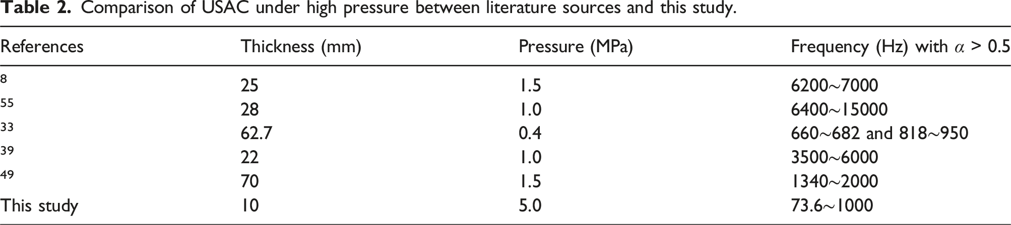
Most of the coatings that can effectively absorb sound in the frequency band below 1000 Hz have a thickness of more than 30 mm. Since thickness of the coating is reduced from 30 mm to 10 mm, the weight of the APBS system is much less than the weight saved in this part. This gives the system a considerable advantage in terms of weight.
Conclusions
The airbag embedding in the Helmholtz resonator model with APBS has been proposed to absorb low-frequency and broadband underwater sound under different hydrostatic pressures. Under high hydrostatic pressure, the anechoic coating model exhibits good low-frequency broadband USAC, while maintaining an ultra-thin and lightweight structure. Some conclusions are drawn as follows: (1) Sound absorption capacity of anechoic coating has been enhanced by APBS. (2) The frequency range of effective sound absorption of the proposed model is 24.5 to 1000 Hz under normal pressure and 73.6 to 1000 Hz under 5.0 MPa. The structural thickness is only 10 mm, which is less than 1‰ of the 15 m wavelength at 100 Hz. (3) To improve the pressure resistance of the coating, priority should be given to materials with higher elastic modulus and thicker airbags. Conversely, to enhance low-frequency sound absorption and achieve a wider sound absorption band, thinner water layer and smaller aperture should be preferred. Therefore, the elastic modulus of the constituent materials, the thickness of the airbag, and the thickness of the water layer have been considered comprehensively according to the specific application requirement to achieve the best sound absorption effect.
The proposed model is expected to have extensive applications in related fields and contribute to the miniaturization of pressure-resistant structure for sound absorption and noise reduction under high hydrostatic pressure.
Footnotes
Acknowledgments
The computation is completed in the HPC Platform of Huazhong University of Science and Technology.
Declaration of conflicting interests
The author(s) declared no potential conflicts of interest with respect to the research, authorship, and/or publication of this article.
Funding
The author(s) disclosed receipt of the following financial support for the research, authorship, and/or publication of this article: this work was supported by the National Natural Science Foundation of China (Grant Nos. 11872186 and 12232007).