
Abstract
An active micro-vibration isolation system for adaptive vibration suppression using piezoelectric stack actuators is presented, along with the discrete time modelling method, real-time adaptive controller design, and hardware implementation. The system comprises piezoelectric stack actuators, capacitive displacement sensors, power amplifiers, signal conditioners, and a real-time computer. A discrete asymmetric Bouc-Wen model is developed to characterize the nonlinear behavior of the piezoelectric stack actuators. System identification is conducted using an improved particle swarm optimization method, specifically the Hybrid PSO-Jaya algorithm, which sequentially integrates the PSO algorithm with the Jaya algorithm. Additionally, an improved adaptive filtering algorithm employing affine projection, referred to as the FXAPA algorithm, is introduced to facilitate real-time control. The efficacy of the proposed active micro-vibration isolation technology is validated through micro-vibration suppression tests.
Keywords
Introduction
One of the pressing issues in the realm of ultra-precision equipment and micro-nano devices is how to safely and reliably isolate micro-vibrations from micro-nano processing and testing equipment.1,2 There are various micro-vibration isolation systems that use different types of actuators such as electromagnetic actuator, 3 magnetostrictive actuator, 4 shape memory alloy actuator, 5 and piezoelectric actuator, 6 etc. With the continuous improvement of the performance of piezoelectric materials, particularly the development of low driving voltage and large displacement piezoelectric stack actuators, piezoelectric stack actuators have been widely used in precision positioning, vibration control, force sensing and other fields. 7
Review of the essential technologies for active vibration control that can be utilized in micro vibration rejection is presented in. 8 Mechanical optimization of MEMS electret-based electrostatic vibration energy harvesters is reviewed in. 9 A novel squeeze mode magnetorheological fluid damper with pre-compression mechanism is presented in. 10 A new type bending moment piezoelectric stack actuator was designed and fabricated to conveniently install the piezoelectric stack on the beam structures in. 11 A novel flexure-based XY platform using a bending hybrid piezoelectric actuator was proposed in. 12 A three-degree-of-freedom piezoelectric actuator is designed, analyzed, fabricated, and tested in. 13 To solve the problem of low displacement transfer coefficient and severe hysteresis of the positioning stage, a two-degrees-of-freedom positioning stage consisting of four actuators driving the working platform through guide beams to achieve X-axis and Y-axis movement, was designed in. 14 An innovative three-stage flexible lever hollow XY piezoelectric platform powered by piezoelectric stack was proposed in. 15 A novel three-phase excitation piezoelectric motor was designed for both macro and micro actuation has been described, analyzed, manufactured, and tested in. 16 A controller consisted of a feed-forward loop based on a novel dynamic Prandtl–Ishlinskii model and a PID feedback control loop, was designed to support a 3-dimensional piezo-driven micro-positioning system for high-bandwidth tracking control in. 17
Unfortunately, there is currently a lack of experimental platforms with multiple degrees of freedom that can be used to test and trial microvibration algorithms. Against this background, this paper presents the implementation and verification of a new active microvibration isolation system based on piezoelectric stack actuators. In addition, nonlinear hysteresis identification and active microvibration control methods are presented to overcome the system performance limitations caused by the hysteresis nonlinearity of piezoelectric actuators.
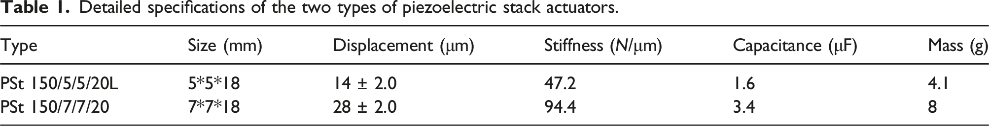
Design of the active micro-vibration isolation test system
To construct a test platform suitable for active micro-vibration isolation system, both the vibration excitation unit and the vibration control unit must be integrated into the same experimental setup. The configuration of the experimental setup for the vibration isolation system is shown in Figure 1. Both the excitation and vibration suppression units employ piezoelectric stack actuators. These actuators are capable of generating displacements in three mutually perpendicular directions (x, y, z) to both simulate and suppress micro-vibration disturbances along these axes. The excitation unit utilizes the PSt 150/5/5/20L, XMT© piezoelectric stack actuator for the z direction, while the PSt 150/7/7/20, XMT© piezoelectric stack actuators are employed for the x and y directions in the excitation unit, as well as for the x, y, and z directions in the vibration suppression unit. Detailed specifications of the two types of piezoelectric stack actuators can be found in Table 1. Structural diagram of the Micro-vibration isolation test system. Detailed specifications of the two types of piezoelectric stack actuators.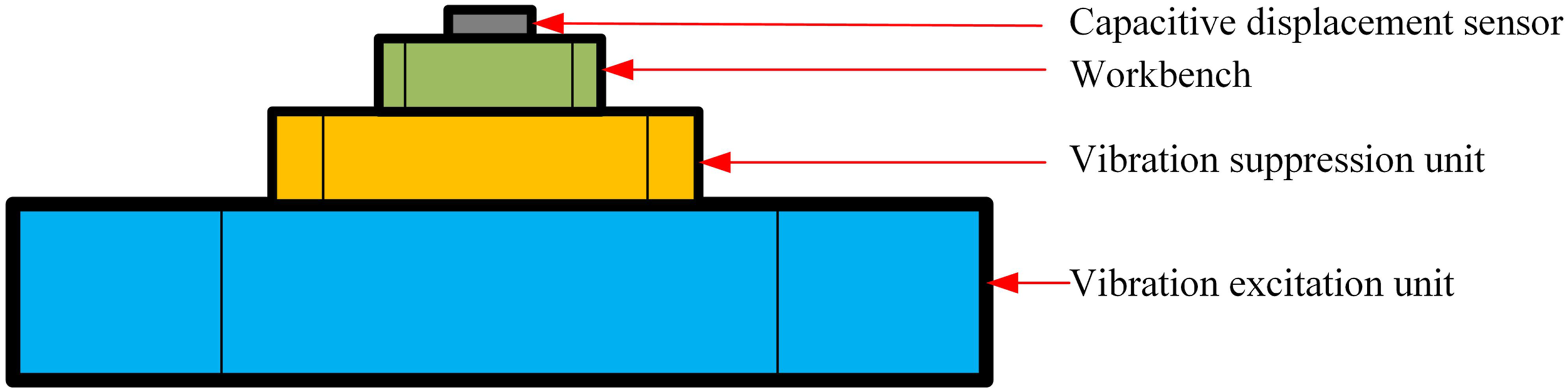
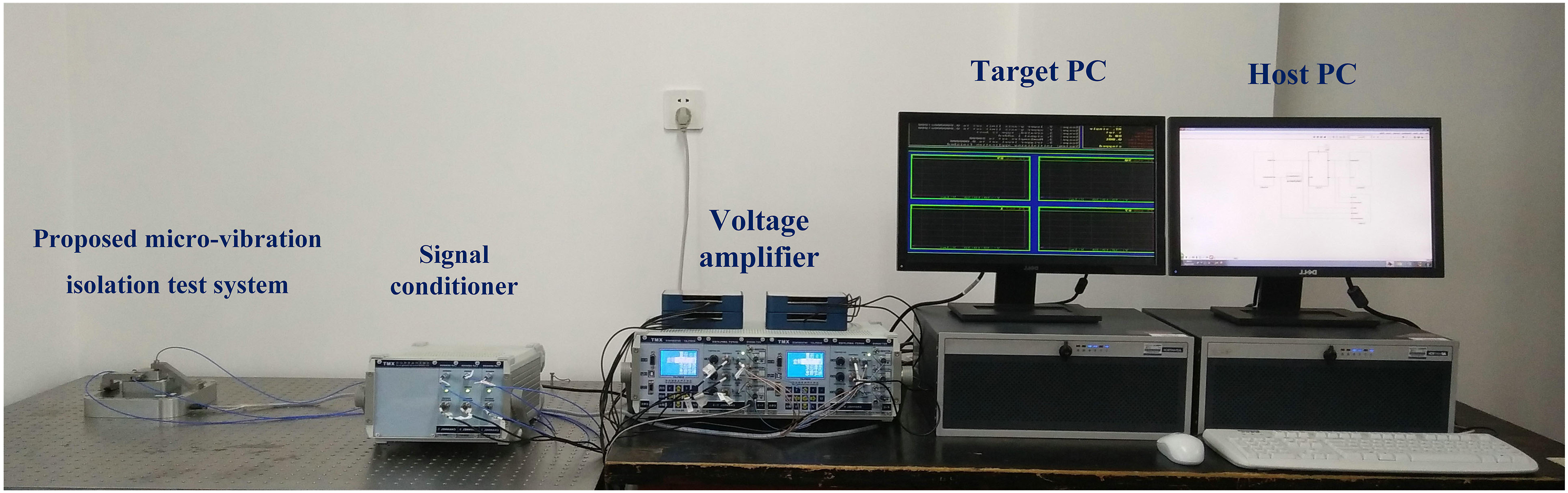
As shown in Figure 2, two industrial computers are selected as the host and target computers for the experimental system. Two data acquisition cards (PCI-6289, NI©) are used, which are installed in the PCI expansion slots of the target computer and serve as A/D input and D/A output ports for the measurement and control system of the experimental system. The output signal of the target computer is first subjected to digital-to-analog conversion (D/A) via the PCI-6289 data acquisition card. The voltage signal generated after D/A conversion is amplified 15 times by a power amplifier (E00. D6, XMT©), which then drives the piezoelectric stack actuator. The reference signal detected by the piezoelectric sensor (M0714. P2, XMT©) is amplified into a voltage signal of 0 V∼10 V by the internal charge amplifier module of the power amplifier and transmitted to the host computer after analog-to-digital (A/D) conversion by the data acquisition board. The error signal detected by the capacitive displacement sensor (E509. C1, XMT©) is processed by a signal conditioner (E09. C1, XMT©) into a voltage signal of 0 V∼10 V, which is then converted by the data acquisition board by A/D before being sent to the host computer. Based on the reference and error signals, the controller performs adaptive adjustment by a control algorithm and assigns the corresponding control signal to the piezoelectric vibration suppression unit. After D/A conversion, the control signal is output and amplified by the power amplifier (E00. D6, XMT©) to a voltage signal of 0 V∼150 V (Figure 3). Configuration diagram of the experimental platform with the proposed micro-vibration isolation test system. Photo of the experimental platform with the proposed micro-vibration isolation test system.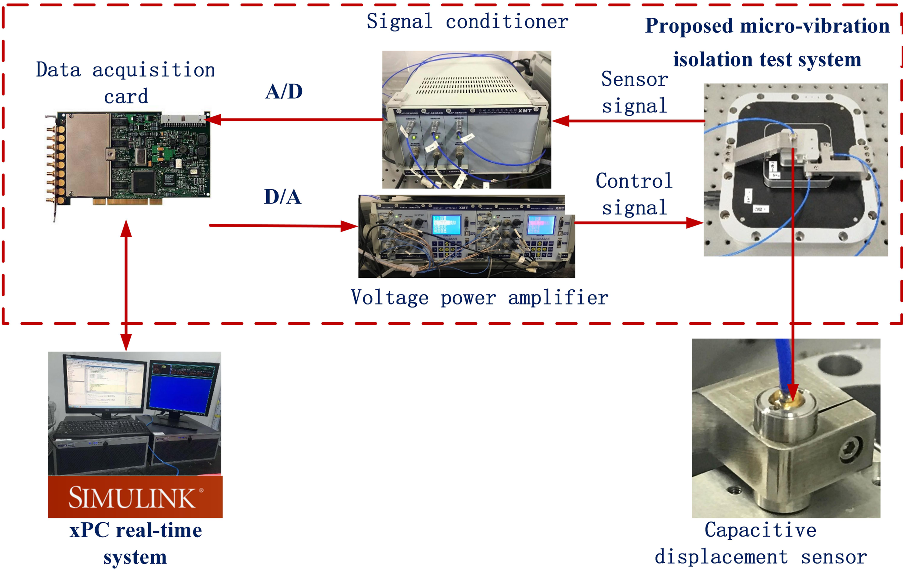
Modelling the nonlinear behavior of piezoelectric stack actuators
Hysteresis nonlinearity of piezoelectric stack actuators
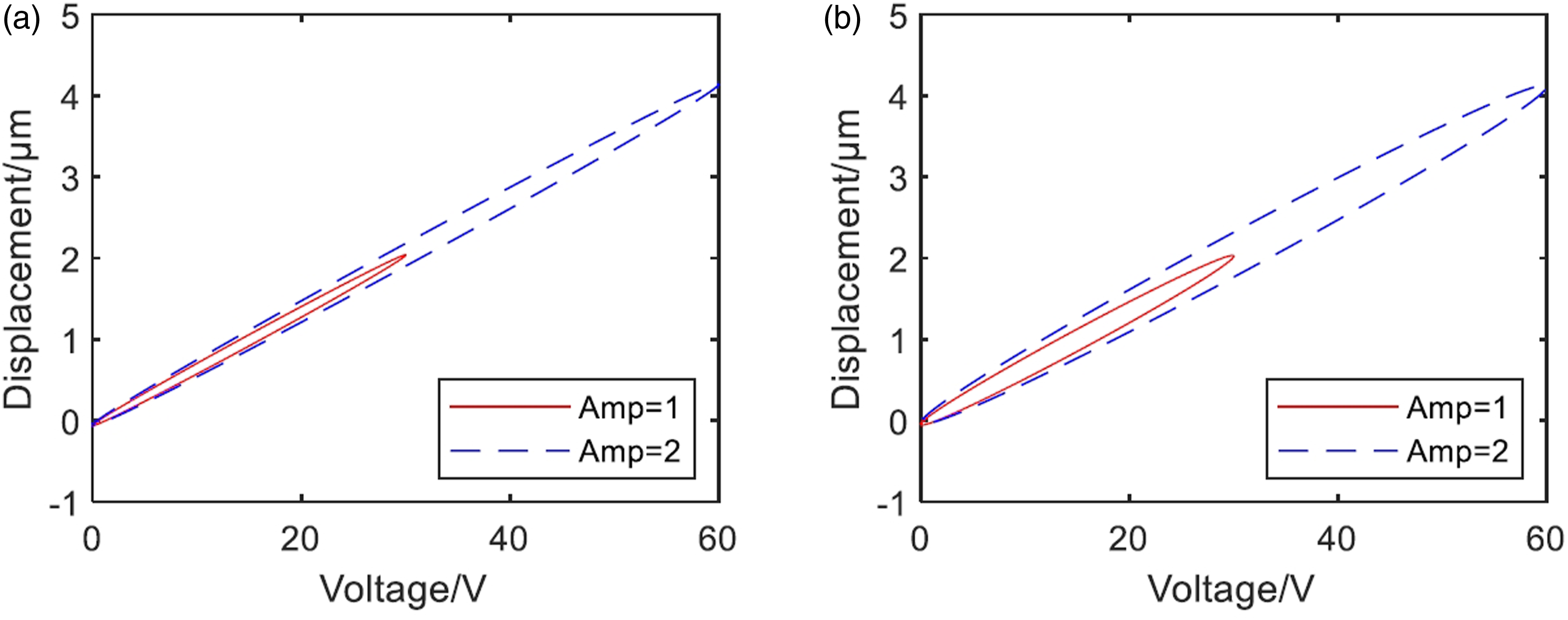
To illustrate, we will use the X direction for vibration control tests. The relationship between input voltage and output displacement of piezoelectric stack actuators is defined by hysteresis nonlinearity, evident in the lack of overlap during the ascending and descending phases, which creates a hysteresis loop.18,19
Figures 4 and 5 illustrate the hysteresis curves of a piezoelectric stack actuator in X direction. The hysteresis curve formed by the ascending and descending curves of the input voltage and displacement of the piezoelectric stack actuator is closed, so the hysteresis curve can be called a hysteresis loop. The output displacement can vary under the same input voltage, and different input voltages can also correspond to the same output displacement. As shown in Figure 4, the output displacement of a piezoelectric stack actuator changes with the frequency of the input voltage; the higher the voltage frequency, the stronger the nonlinearity between the output displacement and the input voltage. As shown in Figure 5, the output displacement of a piezoelectric stack actuator is related not only to the current value of the input voltage but also to the historical values and extreme historical values of the input voltage. The larger the voltage amplitude, the stronger the hysteresis nonlinearity. Hysteresis curves of the piezoelectric stack actuator at different frequencies. (a) Amplitude of 1. (b) Amplitude of 2. Hysteresis curves of the piezoelectric stack actuator at different amplitudes. (a) Frequency of 5 Hz. (b) Amplitude of 2.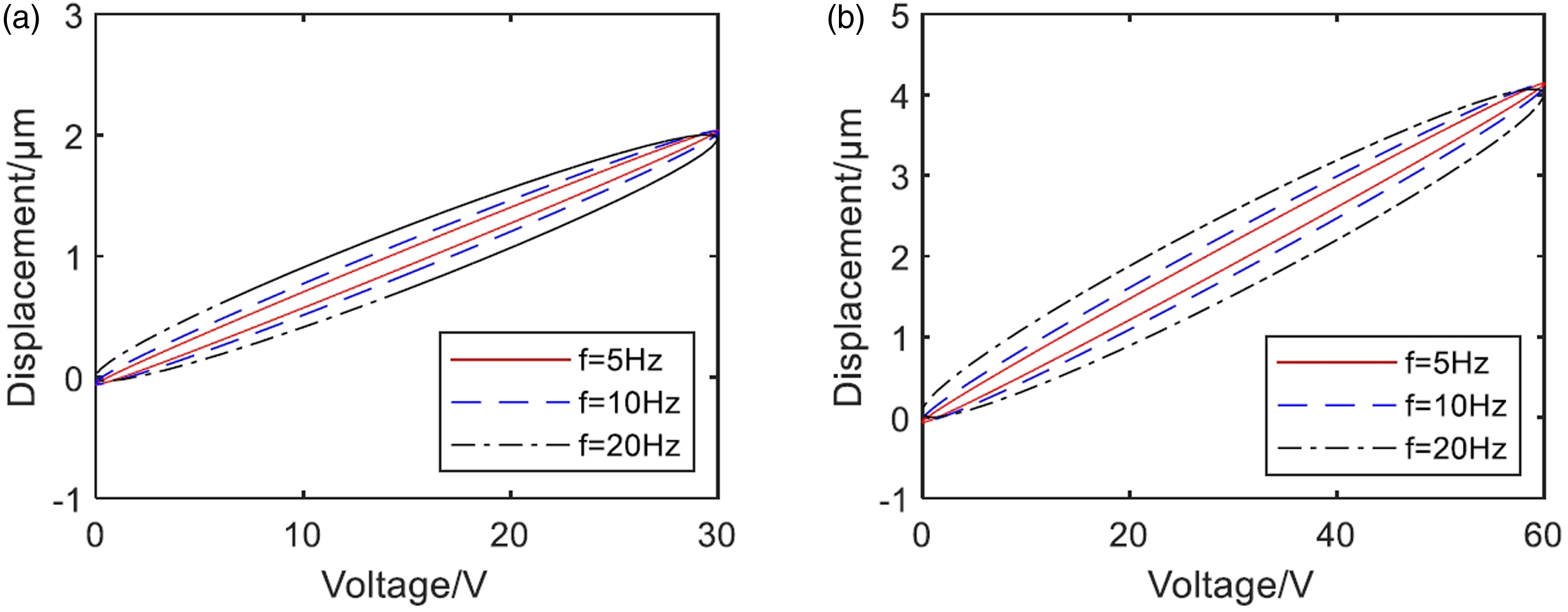
Hysteresis nonlinearity modelling based on discrete asymmetric Bouc-Wen model
Bouc-Wen model can be used to model the hysteresis nonlinearity:
Here,
Let 
Consequently, the asymmetric Bouc-Wen model can be expressed as follows: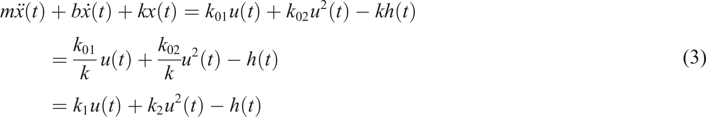

In the context of computer control, employing a discrete-time system model is essential. The discretized Bouc-Wen model is as follows: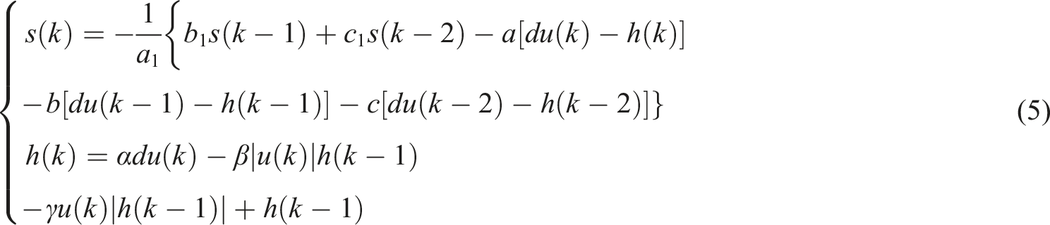
The discretized asymmetric Bouc-Wen model is as follows: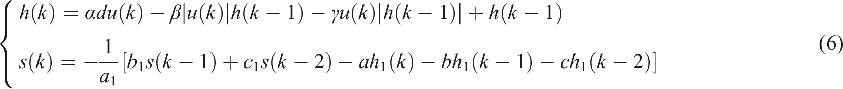
There are five parameters of the discrete Bouc-Wen model need to be identified,
Parameter identification based on improved particle swarm optimization
Improved particle swarm optimization
The particle swarm optimization (PSO) algorithm is a population-based stochastic optimization technique that searches for optimal solutions through cooperation and information exchange within a swarm. It uses simple iterative formulas for speed and position updates, bypassing complex evolutionary operations. PSO includes a unique memory component that dynamically adjusts the search strategy based on progress. Particles in PSO move through the search space towards the best solution found by the swarm to reach the global optimum.
Consider a D-dimensional feasible search space where a swarm consists of a population of n particles 

Here
This study presents the Hybrid PSO-Jaya algorithm, which sequentially combines Particle Swarm Optimization (PSO) with Jaya algorithm to improve optimization performance, by revising update formula of the PSO algorithm to Jaya algorithm’s update equation
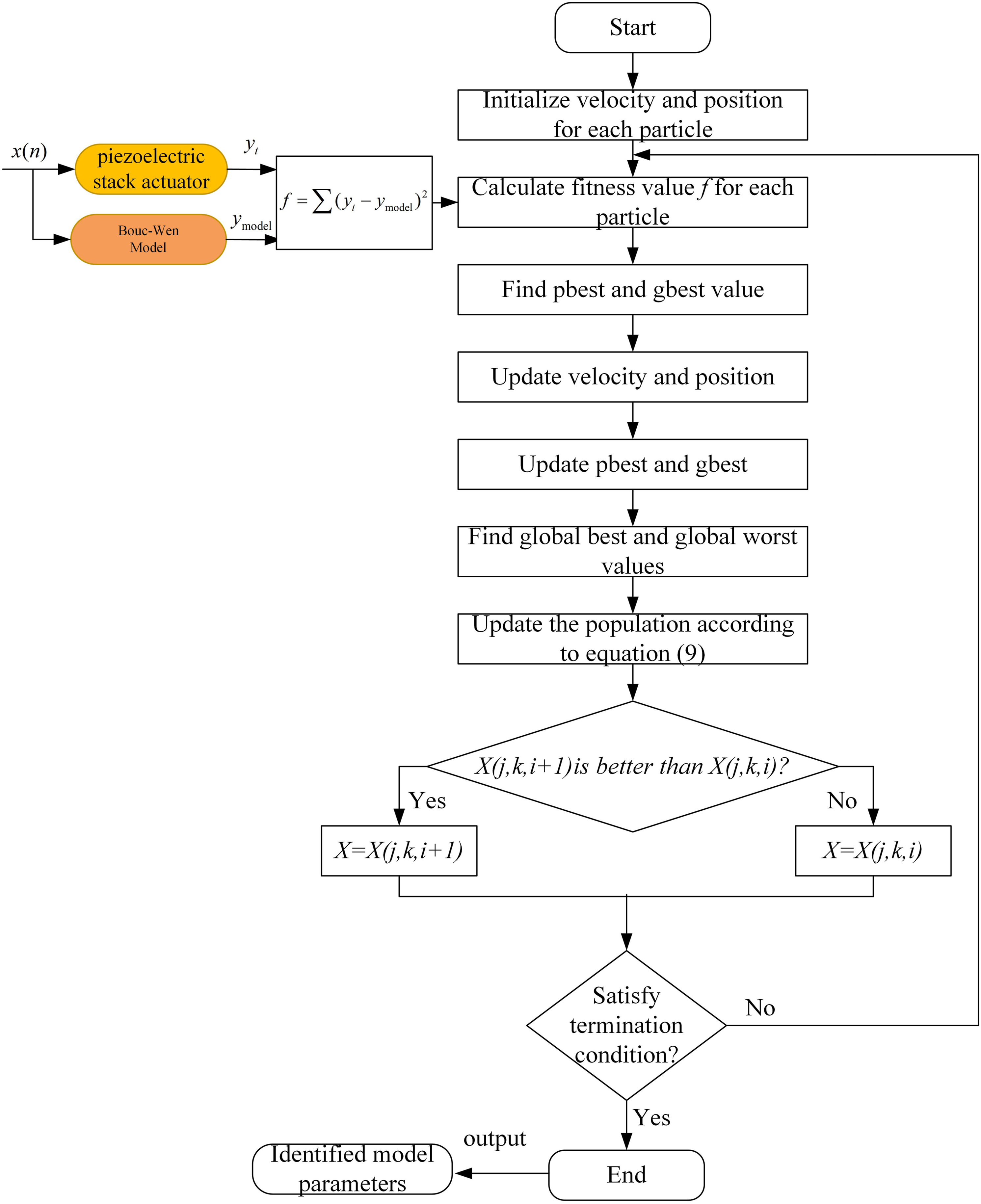
The improved PSO procedure depicted in Figure 6 is outlined as follows: (1) Initialization: Initialization involves setting the velocity and position of each particle in the population. In a D-dimensional search space, each particle is defined by D variables. The personal best position (pbest) of each particle is initially set to its position, while the global best position (gbest) is selected from the initial positions of the swarm. (2) Fitness evaluation: The fitness value is computed for each particle. The best position and its corresponding fitness value are stored for each particle, and the position with the highest fitness value within the population is chosen as the global best (gbest) of the swarm. The fitness is determined by utilizing equation (10). (3) Velocity and Position Update: The velocity and position of each particle are adjusted based on the update equations (7) and (8). (4) Fitness re-evaluation: Following the position updates, the revised fitness values for each particle are computed. A comparison is made between the current fitness of each particle and the fitness linked to its personal best (pbest). In cases where the current fitness surpasses the existing pbest fitness, the pbest is then updated to reflect the current position. (5) Global Best Update: The fitness of each particle is compared with the fitness of the global best (gbest) of the swarm. If a particle’s fitness is superior, the gbest is updated to the position of that particle. (6) Population Update: Determine the global best and worst values and modify the population based on equation (9). (7) Comparison of adaptive values: Comparison of adaptive values involves the calculation of the adaptive value. If the new adaptive value surpasses the previous one, the new position is retained; otherwise, the old position is maintained. (8) Verification of termination: Verification of termination involves evaluating the termination criteria, typically a maximum number of iterations. If the termination condition is not satisfied, the process returns to step 3; otherwise, the iteration is terminated, and the global best solution is output. Following optimization, the optimal parameters for the identified models can be obtained. Improved PSO procedure.
Parameter identification for discrete Bouc-Wen and asymmetric Bouc-Wen model
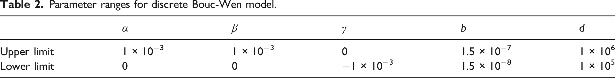
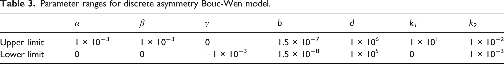
To verify the feasibility of the proposed nonlinear hysteresis model and the algorithm for identifying the model parameters, the discrete Bouc-Wen model and the discrete asymmetric Bouc-Wen model are used to describe the nonlinear hysteresis of the piezoelectric stack actuator (PSt 150/7/7/20) shown in Table 1.

Parameter ranges for discrete Bouc-Wen model.
Parameter ranges for discrete asymmetry Bouc-Wen model.
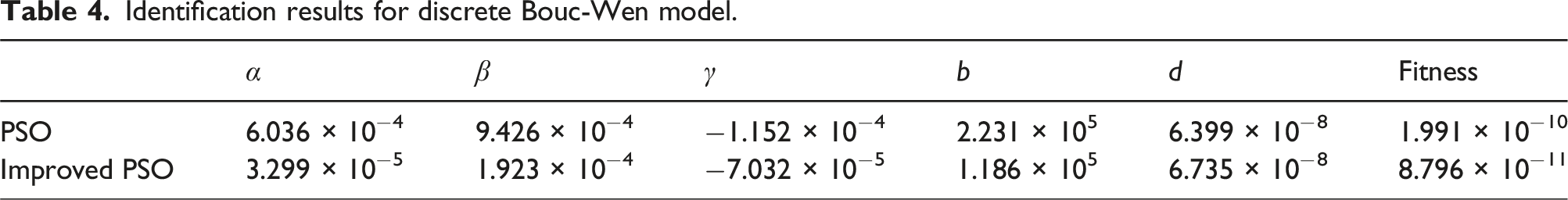
Identification results for discrete Bouc-Wen model.
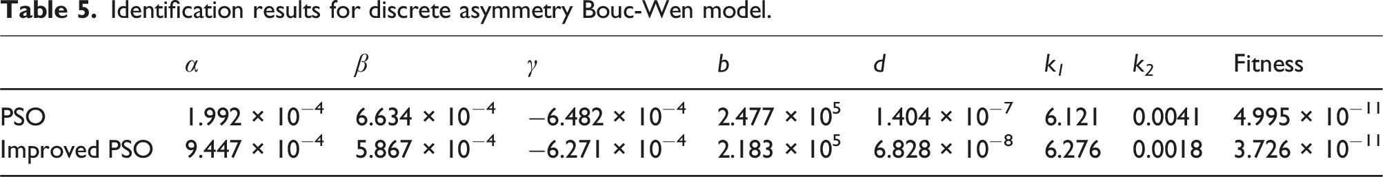
Identification results for discrete asymmetry Bouc-Wen model.
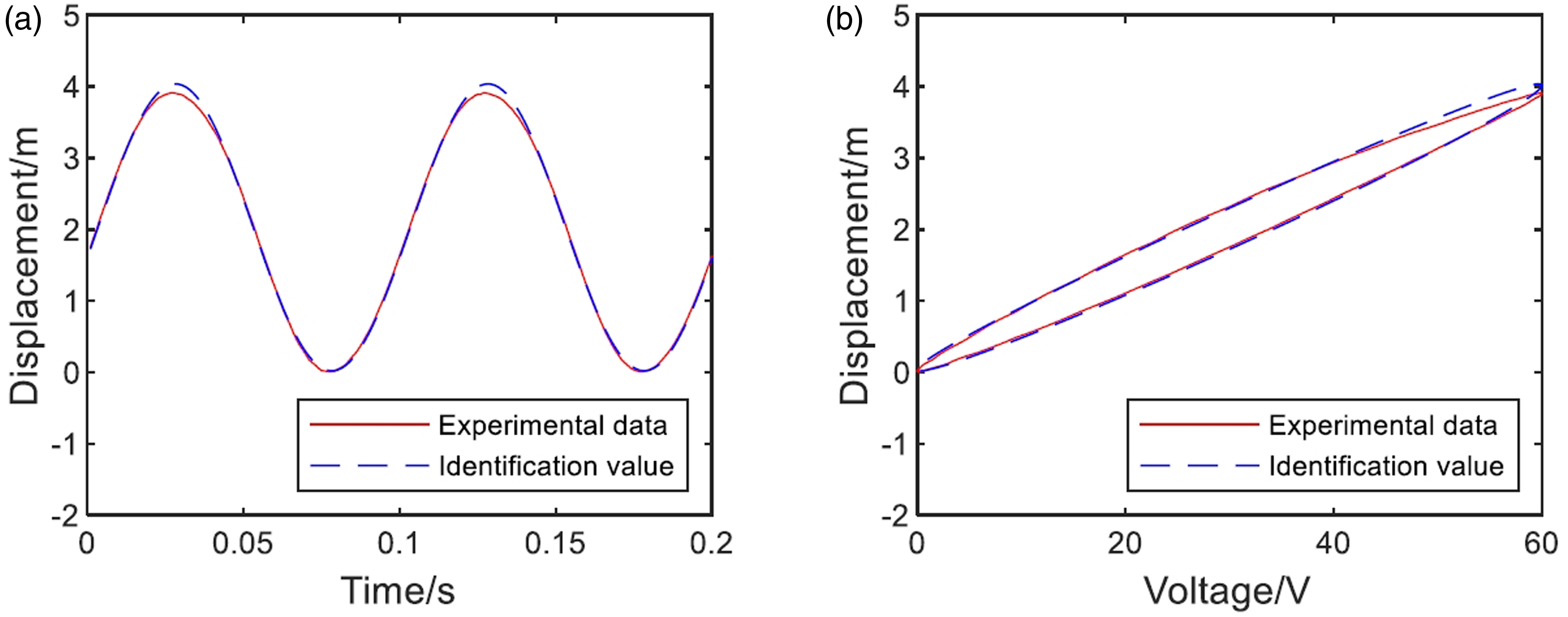
Identification result for discrete asymmetric Bouc-Wen model. (a) Displacement identification result. (b) Hysteresis identification results.
Vibration control algorithm
Filtered-x affine projection algorithm
If the correlation of the input signal is high, the filtered-x affine projection algorithm (FXAPA) can be used to improve the convergence performance by increasing the projection order. The diagram of the FXAPA algorithm is shown in Figure 8. The block diagram of FXAPA algorithm.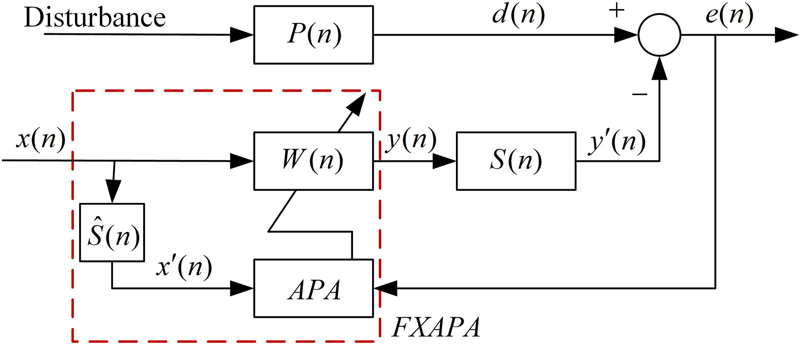
As shown in Figure 8, the reference signal is
Combine the last N input signal vectors into an input matrix: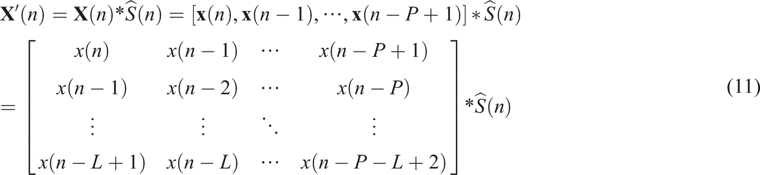
Here, L is the order of the adaptive filter, and p is the projection order.
The weight update equation for the FXAPA algorithm is:
Improved variable step length FXAPA algorithm
To reduce the performance limitations of the FXAPA algorithm, using a variable step size instead of a fixed step size is an effective approach by dynamically adjusting the step size during the convergence process of the algorithm, using a larger step size in the initial phase to improve the convergence speed and a smaller step size near the steady state to reduce the steady state error. By incorporating the design concept of the variable-step-size FXLMS algorithm proposed by Pucha Song 20 into the FXAPA algorithm, we can derive the variable step size FXAPA algorithm (FXVSSAPA).
The step size update equation for the FXVSSAPA algorithm is:
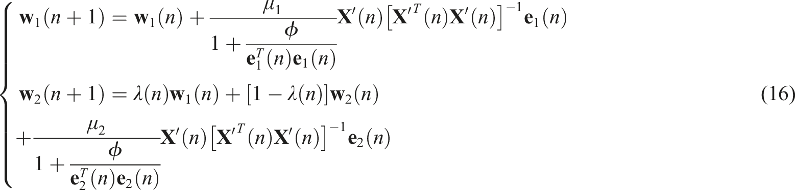
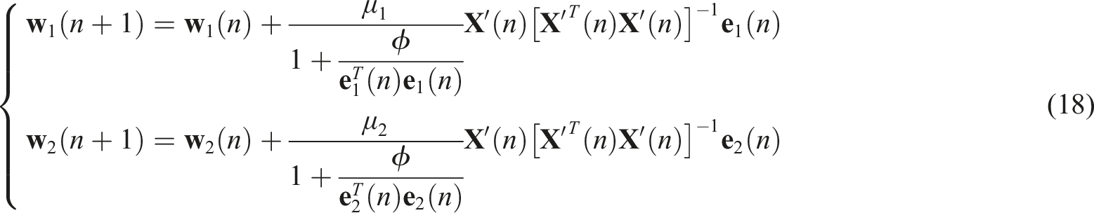
The weight update equation for the FXVSSAPA algorithm is:
The performance of a filter is influenced not only by the adaptive control algorithm, but also by the structure of the filter itself. Utilizing the principles of convex combination and variable step size adaptation, we have developed an algorithm for affine signal projection with convex combination and variable step size (C-FXVSSAPA), as shown in Figure 9. The block diagram of C-FXVSSAPA algorithm.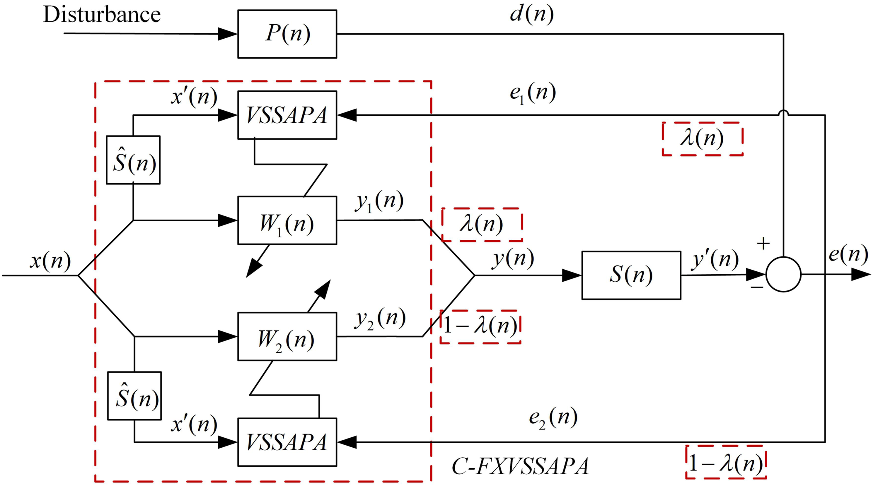
Here, 

The affine projection algorithm (APA) represents a generalized version of the least mean squares (LMS) algorithm, which iteratively adjusts filter coefficients by incorporating a blend of several previous input vectors. This approach results in enhanced convergence speed and improved tracking performance, particularly in situations characterized by correlated input signals.
By projecting the desired signal onto the space spanned by the input signal vectors, the error minimization, thereby ensuring robust performance even in environments characterized by high levels of noise or interference.
The combination of multiple adaptive filters with distinct characteristics, such as a fast-converging yet noisy filter and a slow-converging yet stable filter, facilitates the algorithm in achieving a balance between convergence speed and steady-state error. By employing a convex combination approach, the system can enhance its adaptability to varying signal conditions.
The algorithm benefits from the convex combination of filters, enabling dynamic adjustments to the contributions of individual component filters in response to prevailing error and signal conditions. This feature results in enhanced overall performance.
Variable step size (VSS) algorithms dynamically adapt the learning rate according to the error signal. This feature enables the algorithm to employ a larger step size when significantly distant from the optimal solution to achieve rapid convergence, and a smaller step size when in close proximity to the optimum in order to minimize steady-state error.
By adjusting the step size, the algorithm mitigates problems such as slow convergence or divergence, thereby guaranteeing stability and accuracy in the filter adaptation process.
The amalgamation of these three techniques in the C-FXVSSAPA algorithm yields numerous significant advantages.
Faster Convergence: The employment of affine projection guarantees swift convergence, whereas the convex combination mechanism enhances the filter adaptation process by capitalizing on the advantages of multiple filters.
Enhanced Reduction of Steady-State Error: The utilization of a variable step size mechanism aids in the maintenance of a low steady-state error by dynamically adjusting the learning rate. This process ensures precise adaptation while maintaining stability.
Robustness to Signal Variations: The integration of these techniques enhances the algorithm’s resilience to fluctuations in the signal environment, including variations in signal strength, levels of noise, and patterns of interference.
Experimental tests and vibration control results
The real-time control software for vibration control algorithms was developed on the basis of the MATLAB XPC environment, as shown in Figure 10. SIMULINK program block diagram for real control experiment.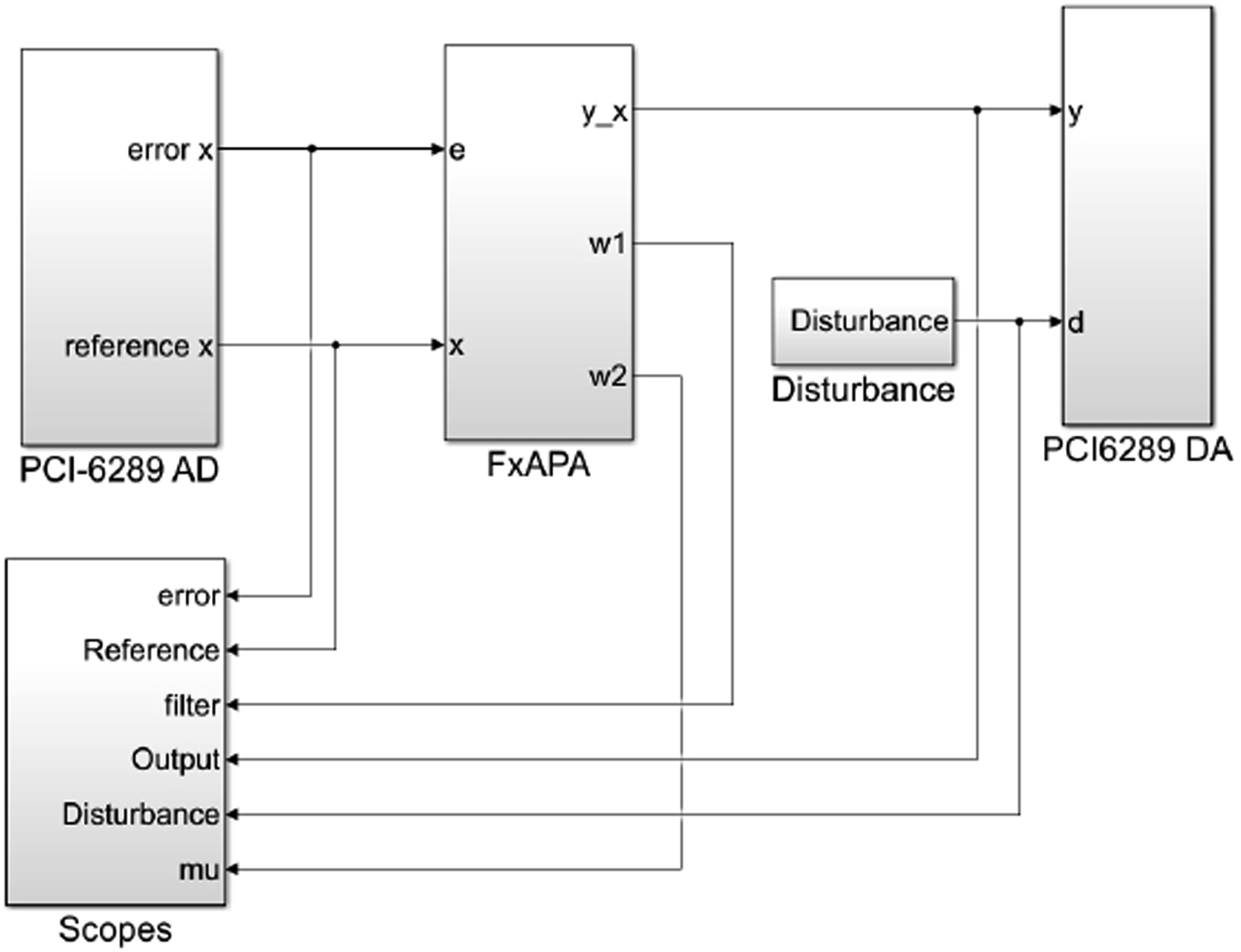
The FXAPA module consists of an adaptive filter and the FXAPA algorithm. The FXAPA algorithm adaptively adjusts the control signal based on the reference signal filtered by the adaptive filter and the error signal detected by the capacitive displacement sensor. The scopes module serves as a display unit for the test parameters. It is used to display the recorded parameter data on the target machine and enables the dynamic observation of various parameter results during the experiment in real time. It also enables the creation of corresponding diagrams based on the recorded data. The PCI-6289 module is responsible for data acquisition and can be further divided into PCI-6289AD for analog-to-digital conversion and PCI-6289DA for digital-to-analog conversion. This module enables data exchange by selecting suitable ports depending on the specific requirements.
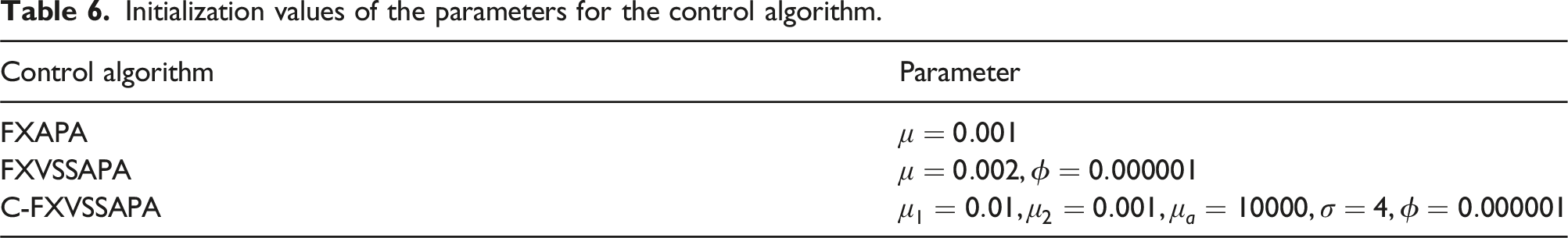
Initialization values of the parameters for the control algorithm.
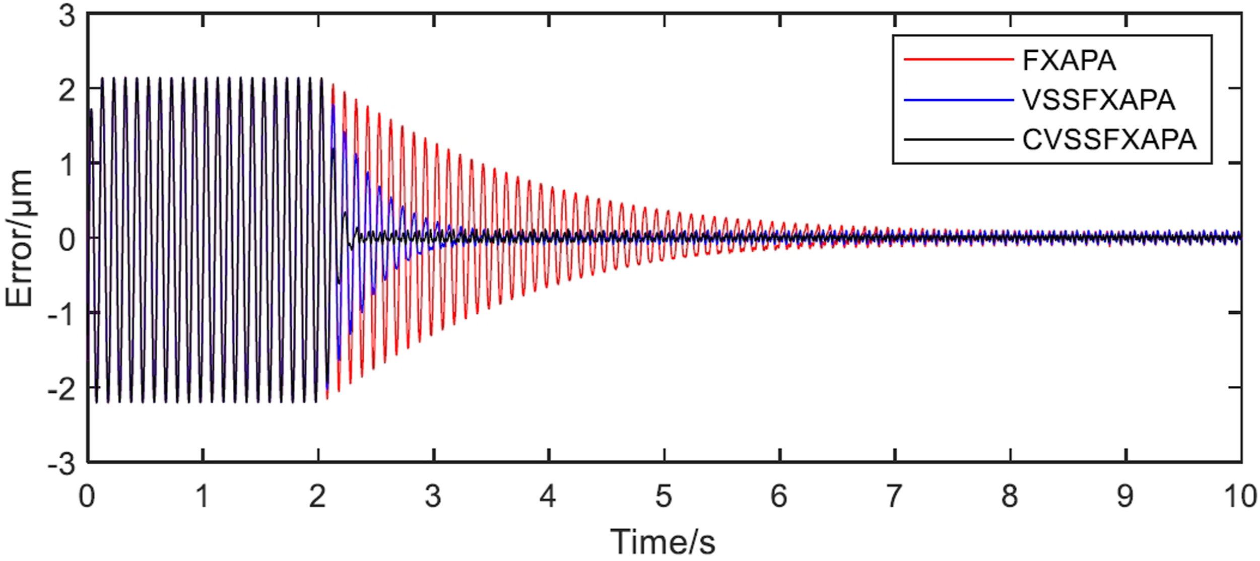
The comparison of the control performance of the three algorithms.
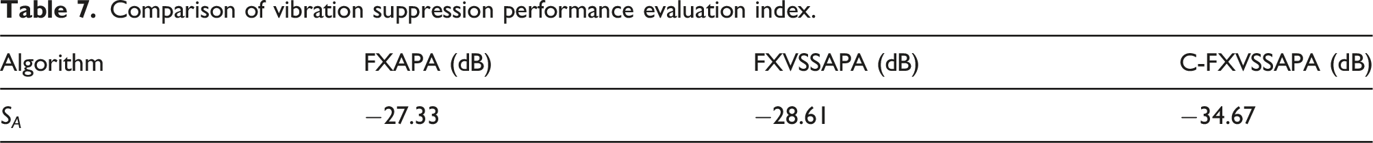
To further quantify the evaluation of the control effectiveness of these three algorithms, the following index was introduced to assess vibration suppression performance: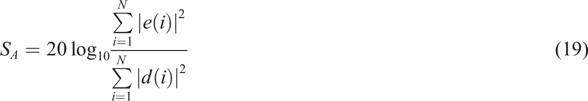
Comparison of vibration suppression performance evaluation index.
Conclusions
This paper presents an active microvibration isolation system with piezoelectric stack actuators. The system architecture integrates the actuator with capacitive displacement sensors, a power amplifier, a signal conditioner and real-time computer control. A discrete asymmetric Bouc-Wen model is used to characterize the nonlinear dynamics of the piezoelectric actuators. System identification is performed using an improved particle swarm optimization algorithm. In addition, an advanced adaptive filtering algorithm using affine projection is employed to enable real-time adaptive control. The effectiveness of the proposed technology is underpinned by experimental tests showing significant suppression of micro-vibrations.
Footnotes
Declaration of conflicting interests
The author(s) declared no potential conflicts of interest with respect to the research, authorship, and/or publication of this article.
Funding
The author(s) disclosed receipt of the following financial support for the research, authorship, and/or publication of this article: This work is supported by National Natural Science Foundation of China (Grant No. 52175101).