
Abstract
In wind tunnel tests, the cantilever sting supporting system often suffers from low-frequency and large-amplitude resonance due to its inherent low structural damping characteristic, resulting in the degradation of data quality and structural safety. To improve wind tunnel testing safety and data accuracy, this paper is dedicated to establish an active vibration control system using piezoelectric stack actuators. A novel methodology of vibration monitoring based on modal transformation, which uses measured strain and a Strain-to-Displacement Transformation (SDT) matrix to reconstruct dynamic displacement field, is proposed herein. Meanwhile, strain sensor positions are optimized by an improved Particle Swarm Optimization (PSO) algorithm to reduce systematic estimation errors of this method. Furthermore, a Back-Propagated Neutral Network (BPNN) is established to implement a self-adaptive control strategy. A series of verification tests are performed to demonstrate the validity of the proposed system. Experimental results indicate that the relative Root Mean Square Error (RMSE) between estimated vibration displacement and measured vibration displacement is less than 3%, and a vibration attenuation of over 14 dB/Hz is achieved in ground tests, proving the superiority of this intelligent active vibration suppression system.
Keywords
1. Introduction
Wind tunnel tests, which are usually launched to evaluate aerodynamic characteristics of aircraft models, play an indispensable role in the aircraft design process. To reduce the aerodynamic interference from supporting system, a tail supporting system, which consists of a test model, a balance functioning as aerodynamic sensors and a long cantilever sting, is widely used in transonic wind tunnels (Ocokoljić et al., 2017). Due to its low structural damping, however, undesirable vibration often occurs under aerodynamic loads, especially in the pitch direction, leading to poor data quality and even structure fatigue failure (Balakrishna et al., 2007; Dai et al., 2020; Post and Corke, 2004). Moreover, the test envelope will be constrained if no vibration suppression is performed. Therefore, it is of vital importance to develop a real-time vibration suppression system for the model-balance-sting system.
Accurate vibration measurement is a necessary prerequisite to achieve high-precision vibration control, however, it is difficult to measure vibration displacement directly in wind tunnel owing to the limitations of narrow operating area and strict working environment. Consequently, a balance is usually used in wind tunnel tests to measure in-plane (axial) dynamic strain of the model-balance-sting system. Considering that in-plane strain can’t directly quantify the vibration amplitude in the pitch direction, finding an out-plane vibration displacement estimation method based on in-plane strain has aroused the interest of many scholars and institutes.
Generally, there are two kinds of solutions when conventional displacement measurement methods are not available. One is building a bridge between strain and displacement based on structural geometry curvature. For instance, Payo et al. (2009). presented a Fiber Bragg Grating (FBG) sensor system to estimate the deflection of a cantilever beam, which used a polynomial function for deformation curve fitting. Nevertheless, the estimation error of this method will be large if the precision of approximation algorithm is low or the number of sensors is insufficient. The other is constructing a Strain-to-Displacement Transformation (SDT) matrix based on modal transformation algorithm (Kim and Cho, 2004; Li and Ulsoy, 1999; Thomas et al., 2020; Warsewa et al., 2020; Zheng et al., 2019). Foss and Haugse (1995) first proposed the concept of modal transformation algorithm and conducted relevant researches to recover the static displacement of a simply-supported plate from measured strains. Inspired by their work, Pisoni and Santolini (1995) investigated the determination of displacement at any given points of a clamped-end beam using two strain gauge sensors. With the use of finite element method to calculate modal characteristics, Bogert et al. (2003) reconstructed the static deformation of a cantilever plate which was subjected to a combination load of bending, shear, and torsion. On the basis of static displacement estimation, Kang et al. (2007) introduced a reconstruction method of dynamic displacement using four FBG strain sensors for a cantilever beam. Furthermore, a two-dimensional modal transformation algorithm was developed in Rapp et al.’s (2009) study and the dynamic displacement field of an acrylic plate was reconstructed using 16 FBG strain sensors. It can be concluded from the above studies that modal transformation algorithm is a high-precision and convenient displacement estimation method, which only requires a SDT matrix and measured strain data, showing tremendous potential in the vibration measurement of wind tunnel models.
In addition, vibration control methods have also attracted an amount of attention from many researchers. Due to the limitation of Passive Vibration Control (PVC) and increasingly higher requirements for control performance, Active Vibration Control (AVC) has been a primary method. Dating back to 1994, Fehren et al. (2001) first proposed a piezoelectric-based active Anti-Vibration-System (AVS) and successfully counteract the vibration of an aircraft model in Europe Transonic Wind-Tunnel (ETW). Nevertheless, the vibration control effect was not satisfactory, especially when the vibration amplitude was large. Based on the similar design philosophy, Balakrishna et al. (2008, 2011) and Acheson and Balakrishna (2011) developed three sets of vibration suppression systems and a series of evaluation experiments were conducted at the NASA Langley Research Center National Transonic Facility (NTF). Results showed effective vibration attenuation and significant improvement in the damping ratio and angle-of-attack testing range. Moreover, it is worth noting that control algorithms are critical for the performance of active vibration damping systems and many related researches over control strategies have been conducted to achieve better control effect. Shen et al. (2018) introduced three controllers based on classical Proportional Derivative (PD) algorithm, Artificial Neural Network PID (NNPID), and Linear Quadratic Regulator (LQR) optimal control algorithm. The evaluation tests of three controllers were conducted in a transonic wind tunnel and 80% reduction of vibration amplitude was achieved by NNPID and LQR algorithm (Chen et al., 2014). Liu et al. (2019) presented a self-adaptive fuzzy PD control method with the self-tuning ability of control parameters and the results indicated that the damping ratio was improved more than four times.
So far many innovations in active vibration control have been investigated for the model-balance-sting system in wind tunnel. In these studies, a strain gauge balance installed at the tip of the cantilever sting is usually used to measure strain feedback signals, however, the strain here is very small compared with that at other positions, which will lead to poor signal-to-noise ratio (SNR) and low-precision vibration data. As a consequence, the vibration control effect will be limited by inaccurate vibration measurement. Therefore, in this paper, a novel vibration monitoring method based on modal transformation and in-plane strain is proposed to improve the existing vibration measurement. Meanwhile, an improved Particle Swarm Optimization (PSO) algorithm is used to determine the positions of strain sensors, which can effectively improve the SNR of strain signals and the estimation precision of vibration displacement. Finally, an active damping vibration control system with self-adaptive Back-Propagated Neutral Network-Proportional Derivative (BPNN-PD) controller and piezoelectric stack actuators is proposed to suppress the vibration in the pitch direction of the sting.
The remainder of this article is organized as follows. Section “Illustration of the active damping vibration control system” illustrates the structural design and working principle of the active vibration suppression system. In Section “Vibration monitoring method,” a novel vibration monitoring method based on modal transformation is introduced and the strain sensor positions is optimized by the improved PSO algorithm. In Section “Vibration control method,” a BPNN-PD control method is proposed to realize vibration suppression and parameter self-tuning. Section “Verification experiments” presents verification experiments and evaluates the performance of the proposed system. Finally, several conclusions and future prospects are summarized in Section “Conclusions.”
2. Illustration of the active damping vibration control system
2.1. Structural design
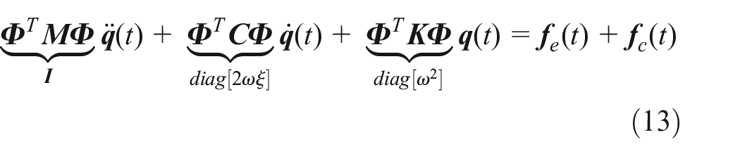
The model-balance-sting system used in wind tunnel is usually a bilateral symmetric structure. Due to the wideband excitations of aerodynamic loads, the structure will vibrate primarily in the pitch direction. Thus, an active vibration suppression system manipulated by piezoelectric stack actuators is proposed herein. As shown in Figure 1, the system is composed of a power amplifier, a low-pass filter, a real-time controller, a strain indicator, several strain gauges functioning as a balance and a pair of piezoelectric stacks mounted at the root of the sting. Significantly, the strain sensor position is optimized to be placed near the root of the sting, instead of being placed at the tip of the sting. Moreover, the strain signals will be transformed to the vibration displacement on the mass center of the aircraft model by modal transformation algorithm in next section. Then according to the estimated vibration displacement, piezoelectric stack actuators can stretch or contract to generate corresponding output force to resist the dynamic bending moments caused by aerodynamic loads. To obtain satisfactory vibration suppression effect, the controller should have excellent control algorithms and data transmission and processing capabilities, which will be described in Section “Vibration control method.”
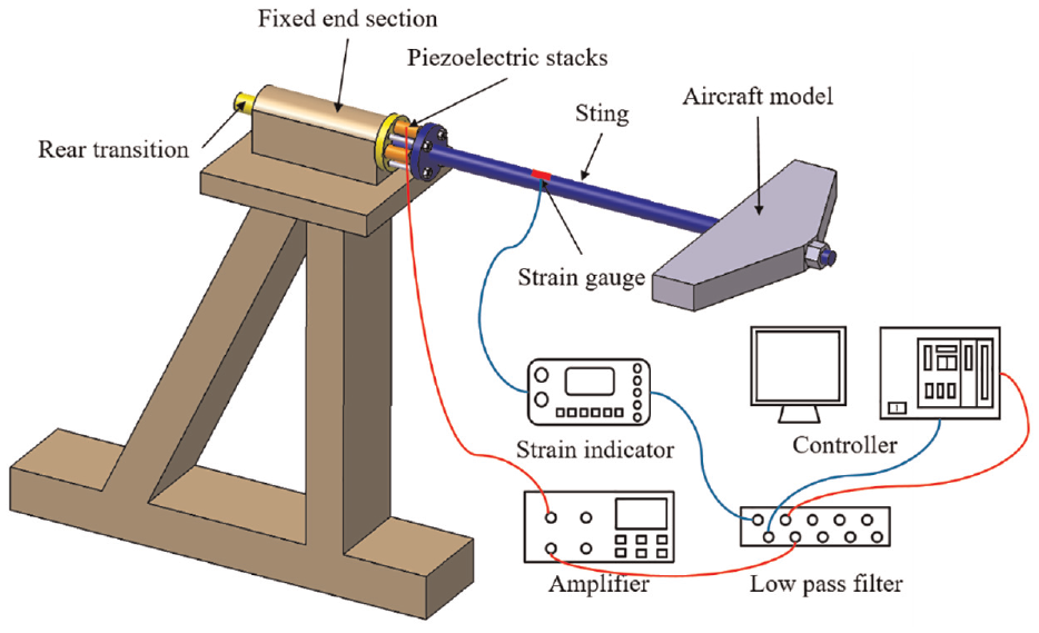
Schematic diagram of the piezoelectric-based active vibration suppression system.
2.2. Working principle
During wind tunnel tests, there are two types of forces acting on the aircraft model, namely the static lift force and the dynamic force excited by airflow turbulence. The expression of the force vector is given by
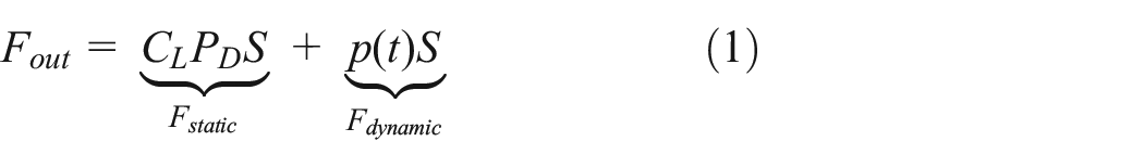
where
Noticeably,
Principle of the active vibration suppression system.
3. Vibration monitoring method
3.1. Modal transformation algorithm
According to mechanical vibration theory, the displacement can be expressed by multiplying an infinite number of mode shapes by weighting factors


where
Through the transformation of equation (2), the modal coordinates

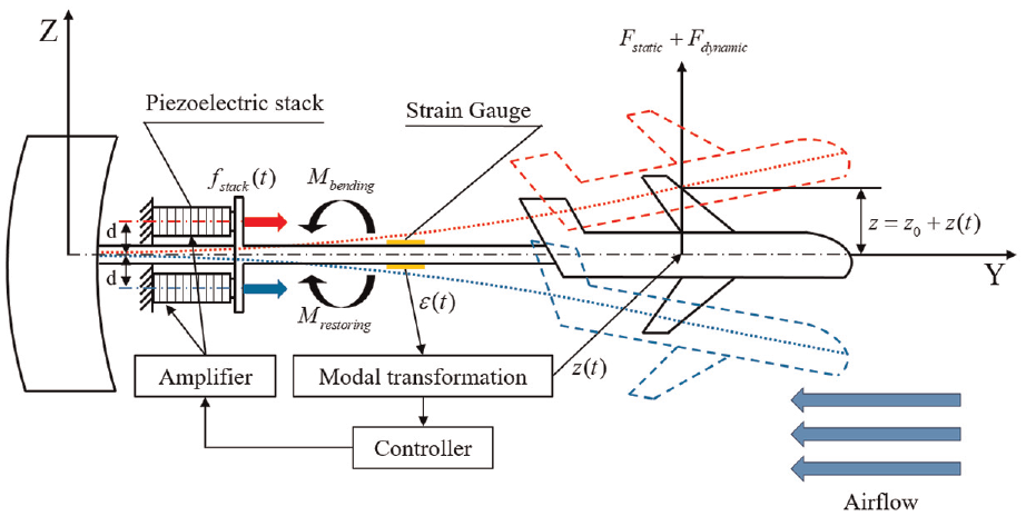
If we substitute equation (3) to equation (1) to eliminate modal coordinates
where
According to equation (5), displacement can be easily calculated by using the SDT matrix and measured strain vector, which is called modal transformation algorithm. As shown in equation (5), the matrix
3.2. Improved particle swarm optimization algorithm
Although many convincing results has been obtained to verify the feasibility of modal transformation algorithm, few studies have been conducted on the optimization of strain sensor positions, which has a significant influence on the displacement estimation accuracy. In order to obtain more precision displacement estimation results, an improved Particle Swarm Optimization (PSO) algorithm is used to determine optimal strain sensor positions.
PSO is a typical swarm intelligence optimization algorithm that simulates the predation behavior of birds. In the whole evolution process, each particle continuously changes its velocity and position by tracking its own individual historical optimal fitness value and global optimal fitness value until it reaches the optimal position (Tran-Ngoc et al., 2020; Zhang and Xia, 2017). For a standard PSO algorithm, it can be expressed by
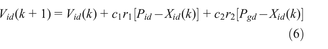

where
In order to avoid the precocity of particles, an inertial weight variable based on Linearly Decreasing Weight (LDW) strategy was introduced in Eberhart’ study to improve the standard PSO algorithm (Shi and Eberhart, 2002). The improved velocity update formula can be expressed by
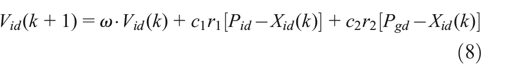
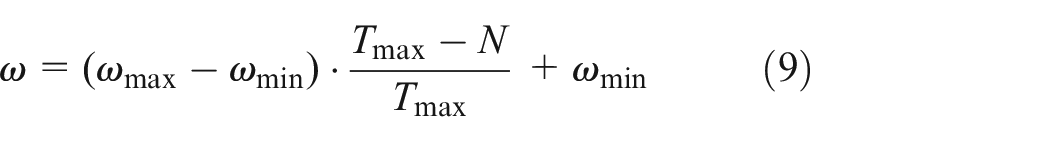
where
As mentioned in previous studies, the Condition Number (CN) of the SDT matrix, which indicates the maximum relative computational error that may be caused by the variation of strain measurement, is closely related to strain sensor positions. Additionally, CN is also an important index for information conservation during matrix operations which reflects the pathologies of a matrix. Mathematically it is defined as

where
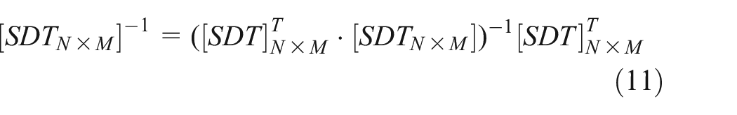
It should be noted that we usually use the same number of strain sensors as the displacement measuring points to make the SDT matrix be a square matrix. Therefore, we can use conventional methods to calculate its inverse matrix. But for a rectangular SDT matrix (N × M), in this paper, the inverse matrix refers to the generalized inverse matrix (left inverse matrix), which can be calculated by
The larger the CN, the more seriously the calculation results are affected by the measuring error of the strain data. Therefore, based on the minimum condition number criterion, it is feasible to use CN as the optimization objective of the improved PSO algorithm to find optimal strain sensor positions.
3.3. Simulation process
To apply modal transformation algorithm to the vibration monitoring of the sting, a finite element simulation should be conducted to obtain modal characteristics and SDT matrix. As shown in Figure 3, the simulation process mainly includes modal analysis, sensor placement optimization, calculation of the SDT matrix, and a structural static analysis for validity verification. In summary, the simulation process is a continuously iterative optimization process until the estimation error of the SDT matrix is acceptable.
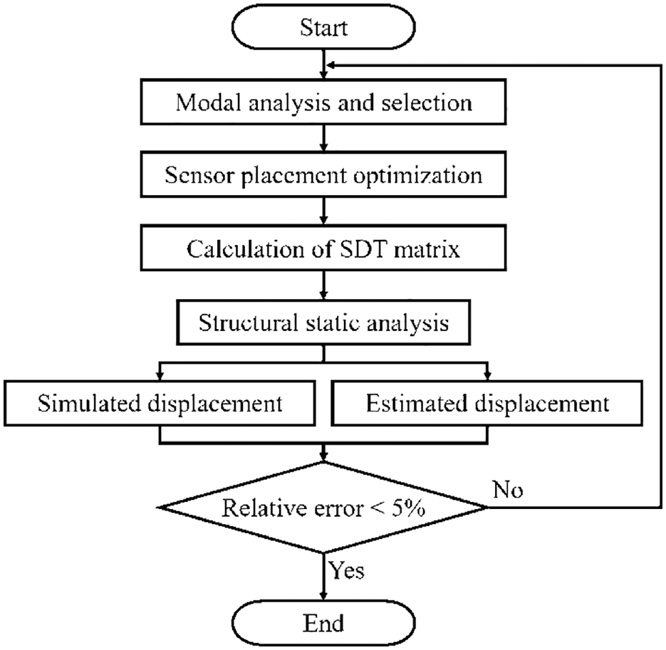
Simulation flowchart of modal transformation algorithm.
3.3.1. Modal analysis and selection
Modal analysis is required to obtain displacement and strain mode shapes, however, it is not realistic to keep all the modes. It is crucial to select the modes which make significant contributions to the vibration displacement in the pitch direction. Considering that low-order modes usually dominate the vibration of the model-balance-sting, the first two pitching modes are used to calculate the SDT matrix in this paper. A finite element model is created through ANSYS. Besides, to facilitate the subsequent processing, a hexahedral meshing method is used to divide the sting model and the element size of mesh is set 5 mm to reduce the computational cost. Then a modal analysis is conducted to obtain mode shapes as shown in Figure 4.
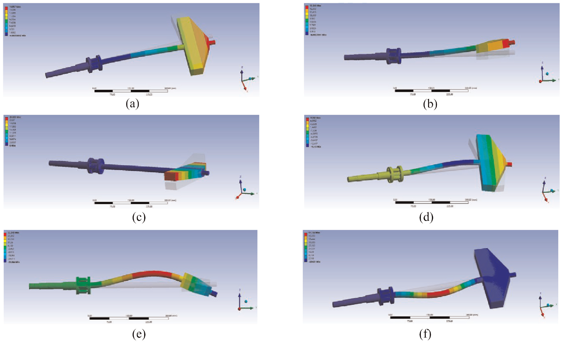
The first six modes of the sting: (a) first bending mode, (b) second bending mode, (c) third torsional mode, (d) fourth bending mode, (e) fifth bending mode, and (f) sixth bending mode.
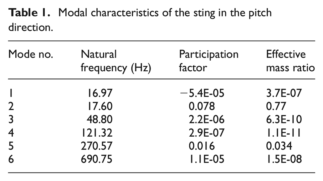
As shown in Table 1, the participation factor here refers to the ratio of the sum of modal participation mass to the modal mass while the effective mass ratio refers to the ratio of the square of the participation factor to the modal mass. Both of the two parameters can effectively reflect the contributions of different modes in the pitch direction. According to the modal participation factor and effective mass ratio in Table 1, the second and fifth modes can be considered as the bending modes in the pitch direction. Therefore, these two modes are ultimately selected to calculate the SDT matrix.
Modal characteristics of the sting in the pitch direction.
3.3.2. Sensor placement optimization
The coordinate system of the cantilever sting is shown in Figure 5. The coordinate origin is set at the left end of the equal-diameter sting. The axial direction of the sting is the y-axis while the pitch direction is the z-axis. Two points, namely the mass center and the tip of the aircraft model, are selected as the vibration displacement monitoring points. Since two pitching modes are used to recover the vibration displacement, at least two strain measuring points should be selected based on the definition of the SDT matrix. Thus, a [2 × 2] SDT matrix which uses two strain measuring points is constructed. However, the estimation accuracy of modal transformation algorithm will be poor if the positions of strain sensors are still at the tip of the sting. Consequently, it is of vital importance to optimize the locations of strain sensors for the improvement of signal-to-noise ratio (SNR) and the estimation accuracy.
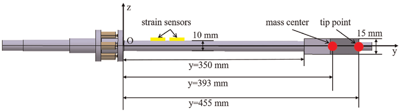
Schematic diagram of strain sensor placement.
The sting can be simplified as a Bernoulli-Euler beam, which means that the maximum strain usually occurs on the upper or lower surface when it vibrates in the pitch direction. Moreover, the strain on the upper and lower surfaces are numerically equal but opposite to each other. Thus, strain sensor positions are limited to the upper and lower surface for monitoring the vibration in the pitch direction. Due to the fact that the mesh size is set 5 mm, continuous modal data of the sting are not available. To obtain continuous modal data for sensor placement optimization, this paper uses a polynomial curve fitting method based on least square principle to fit strain mode shapes. As shown in Figure 6, the fitting curves of strain mode shapes show good approximation to the numerical results calculated by finite element simulation, indicating the effectiveness of these fitting curves.
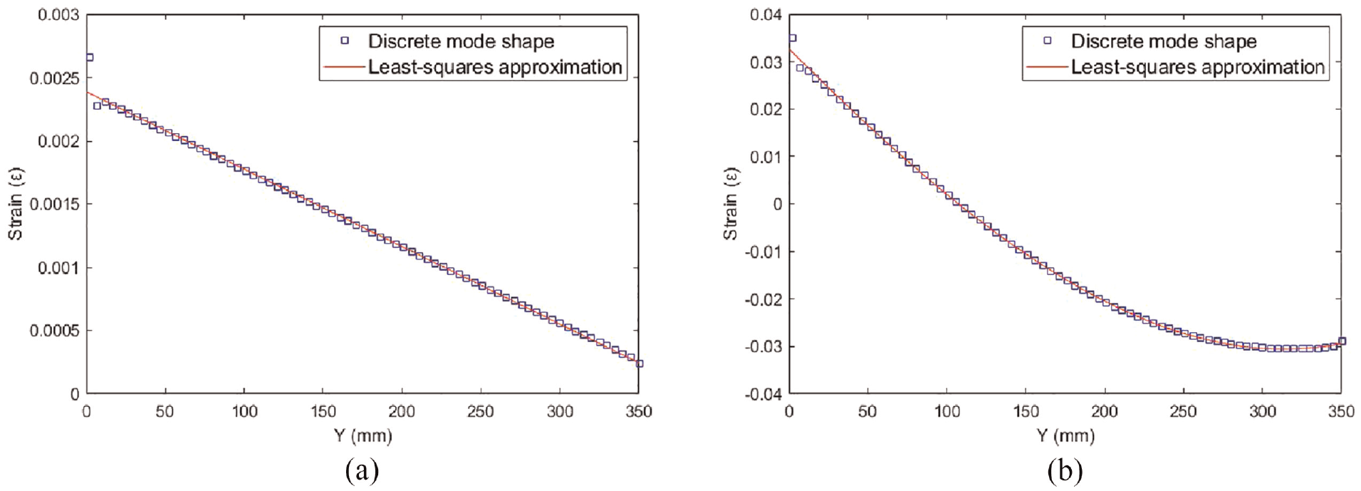
Fitting curves of the strain modes in the pitch direction: (a) first strain mode shape and (b) second strain mode shape.
Then positions of strain sensors are optimized in the range of 0–350 mm by the improved PSO algorithm. The parameters are set as follows: the number of particles is set 20, the dimension is set 2, the learning factors are set 2, and the maximum iteration number is set 50. The minimum and maximum of inertia weight are set 0.4 and 0.9, respectively. Furthermore, the boundary conditions that limit the velocity and position of particles are also set to guarantee convergence. The velocity range is set [−1, 1] and the position range is set [0, 350]. The final fit-ness iteration curve of the optimal particle is shown in Figure 7.
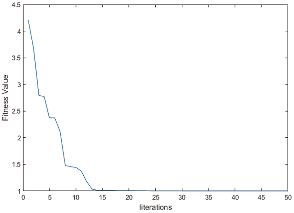
Fitness curve of the optimal particle.
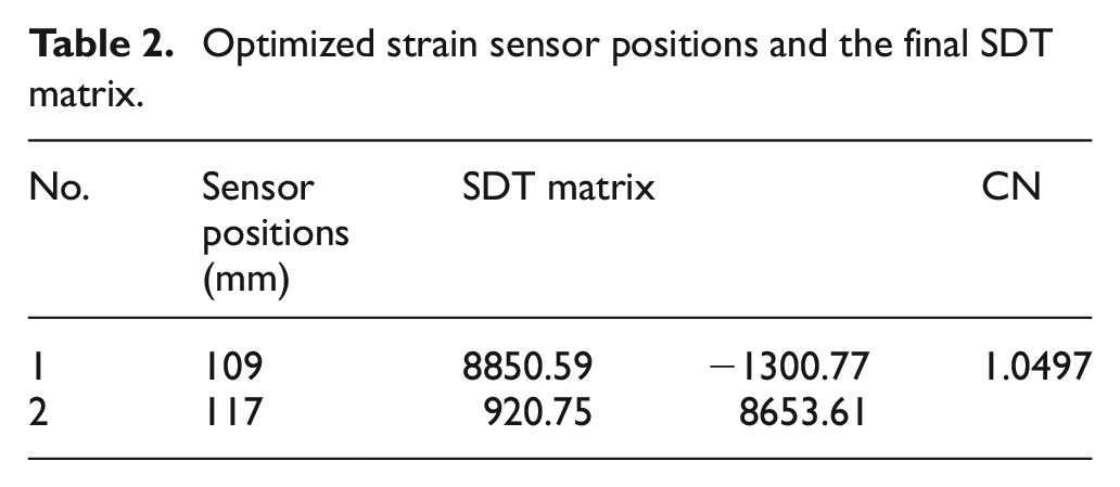
The optimized results and the SDT matrix are shown in Table 2. It can be clearly seen that the strain sensors should be placed near the root of the cantilever sting.
Optimized strain sensor positions and the final SDT matrix.
3.3.3. Structural static analysis
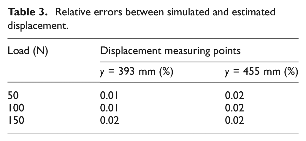
To demonstrate the validity of the SDT matrix, a structural static analysis is carried out under three different load conditions which are the surface pressures of 50, 100, 150 N acting on the upper of the aircraft model. The static deformation of the sting is calculated through simulation and modal transformation algorithm, respectively. As shown in Table 3 and Figure 8, the relative errors between simulated and estimated displacement are all less than 1%, which is in line with the expected target. Therefore, it can be considered effective to monitor the real-time vibration displacement of the model-balance-sting using the SDT matrix.
Relative errors between simulated and estimated displacement.
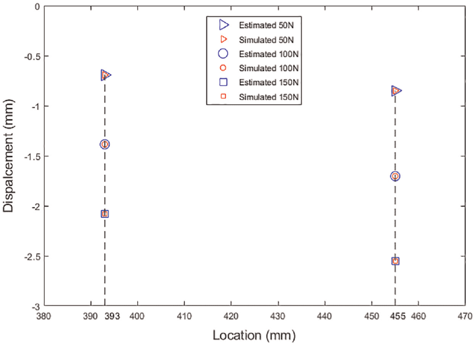
Comparison between simulated and estimated displacements.
4. Vibration control method
Since the majority of vibration energy in the pitch plane is concentrated around the first resonant frequency of the model-balance-sting system, the main objective of control is to eliminate the vibration of the first pitching mode. In this section, the theoretical model of the model-balance-sting system is firstly introduced to analysis the vibration characteristics. System identification is then conducted to calculate initial PD control parameters based on empirical formula. Finally, a Back-Propagated Neutral Network (BP-NN) is used to automatically adjust PD control parameters for various testing conditions.
4.1. Theoretical modeling and analysis
As shown in Figure 1, the model-balance-sting can be simplified as a Euler-Bernoulli beam system. The continuous beam system can be converted into a mass-stiffness-damping system with finite degrees of freedom by discretization. Assuming that the continuous system is divided into n discrete nodes, the dynamic model of the cantilever beam system can be expressed as

where
According to the modal decomposition principle, the vibration displacement is decoupled in generalized coordinate system. Suppose the cantilever beam system is a proportional damping system and the damping matrix
where
Therefore, the dynamic equation of the cantilever sting can be discretized into
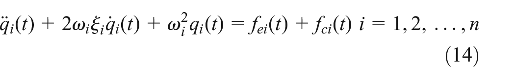
where
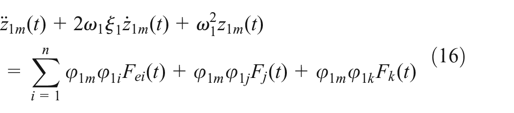
Since the sting vibration is mainly caused by the first pitching mode, by discarding the other modes except the first pitching mode, the displacement response of the cantilever sting can be written as

Assuming that the control forces of two piezoelectric actuators act on the nodes j and k, the control forces can be expressed by
Since the velocity is used as the feedback for the closed-loop control system in this paper, the control forces can be defined as
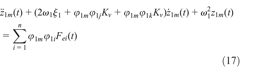
As shown in equation (17), the control force can be considered as the appending damping of the model-balance-sting system. Therefore, the vibration suppression system is essentially an active damping control system.
4.2. Self-adaptive BPNN-PD control
A large number of wind tunnel tests shows the rapid and stable control effect of PD controller, which so far is still one of the most widely used and mature controllers. However, the tuning of control parameters is a tough task for wind tunnel testers. Although the control parameters can be determined based on expert experience, these parameters are not suitable for all testing conditions. The past decades have witnessed the vigorous development of artificial neural network. Therefore, to realize the self-tuning of control parameters, a self-adaptive PD control method is proposed, which consists of a classical PD control algorithm and a Back-Propagated Neutral Network (BPNN). For a classical PD control algorithm, the control signal is expressed as
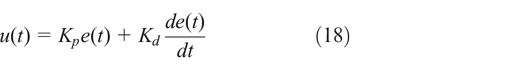
where
The initial control parameters should be preset to avoid vibration divergence before automatically adjust the control parameters according to real-time feedback data. Hence, based on a widely-used empirical formula (Dai et al., 2019), the control parameters are determined by
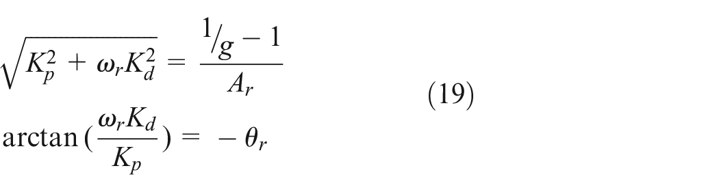
where
Although a PD controller can realize rapid and stable vibration control when the testing condition is ideal or definite, it can’t adapt to various testing conditions such as different Mach numbers or angles-of-attack. Therefore, this paper uses BPNN to achieve self-adjustment of control parameters. As shown in Figure 9, the PD controller first converts the measured strain data into velocity signals and then updates control parameters in real time by the gradient descent (Delta learning rule).
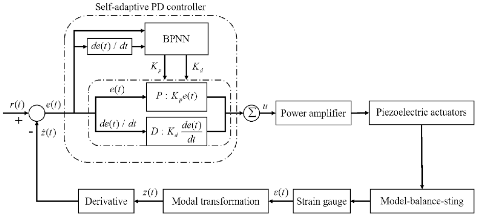
Schematic of self-adaptive PD control method.
In this paper, a back-propagated neural network with three layers is used to automatically adjust control parameters. According to the delta learning rule and using the same learning rate, the recursive update formula of control parameters is established:
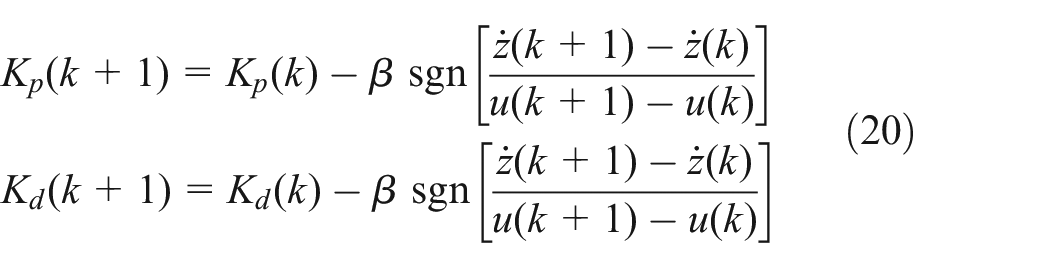
where
It is worth mentioning that learning rate
5. Verification experiments
5.1. Experimental setup
The experimental devices of the active damping vibration control system are shown in Figure 10. To realize the strain measurement, two full-bridge Wheatstone bridge circuits are built in two dynamic resistance strain indicators (ADAM-3016), which simulates the function of a real test balance. Since strain sensors are quite light and mounted at the root of the cantilever sting, this vibration measurement has little aerodynamic interference to the aircraft model. Moreover, two laser displacements sensors (CD5-85) are used to simultaneously measure vibration displacement. The strain and displacement data are collected and processed by a data acquisition equipment (DS-1104). Through the comparison between measured displacement and strain-based predicted displacement, the vibration monitoring method is verified. Noticeably, piezoelectric stacks are used as a shaker in vibration monitoring tests while in vibration control tests they are considered as an active damper for vibration suppression. All programs, including the control algorithm, data acquisition and storage, and signal output are developed based on LabVIEW and integrated in the controller (PXIe-1071 with a PXI-7841R FPGA mode card inserted). Besides, in order to drive piezoelectric stacks, a power amplifier (XE517.00) is used to amplify the control voltage.
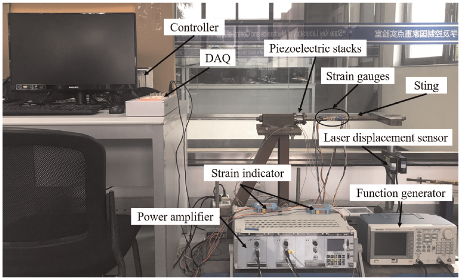
Photograph of the active vibration suppression system.
5.2. Vibration monitoring tests
In vibration monitoring tests, a function generator (AFG-3021C), a power amplifier and a pair of piezoelectric stack actuators are used to provide vibration excitation. The sting is forced to vibrate in the pitch plane while its dynamic strain and displacement are simultaneously collected and transmitted to the principal computer. In the data acquisition equipment (DS-1104), the strain data is also copied and converted into estimated displacement data based on modal transformation algorithm. Thus the principal computer will receive three kinds of vibration signals, namely measured strain, measured displacement, and estimated displacement, respectively. The principle of vibration monitoring tests is shown in Figure 11.
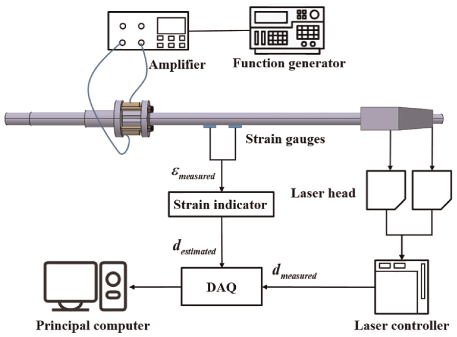
Schematic of the vibration monitoring experimental platform.
In order to quantitatively evaluated the relative errors between measured displacement and estimated displacement, the relative Root Mean Square Error (RMSE) is introduced:
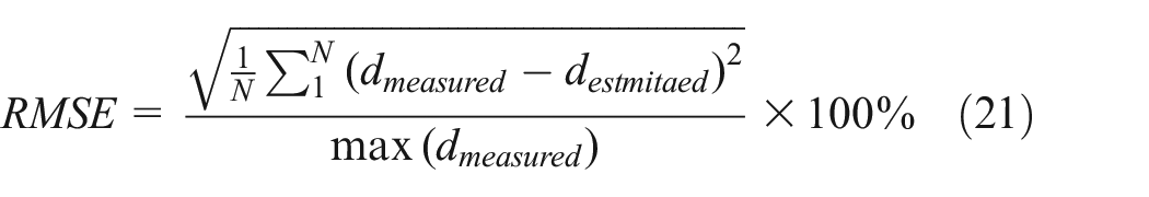
where
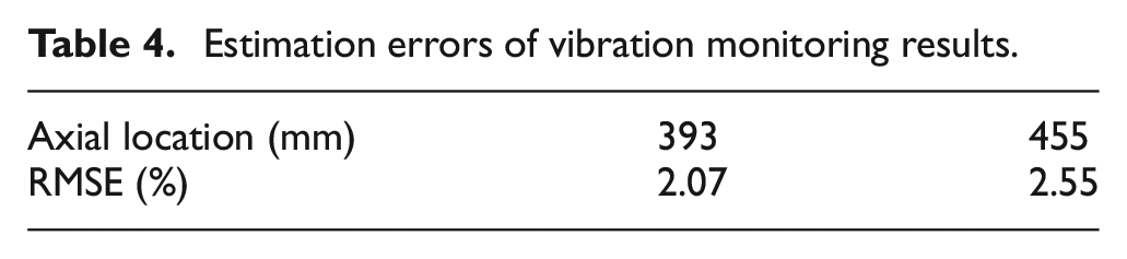
The model-balance-sting system is subjected to the excitation of first pitching modal frequency and the vibration displacement are obtained through direct measurement and indirect estimation, respectively. As shown in Figure 12, the estimated displacement curve shows good agreement with the measured displacement curve. More importantly, it can be seen from Table 4 that the relative RMSEs are smaller than 3%, which indicates that modal transformation algorithm has sufficient precision to monitor the vibration displacement of the wind tunnel model.
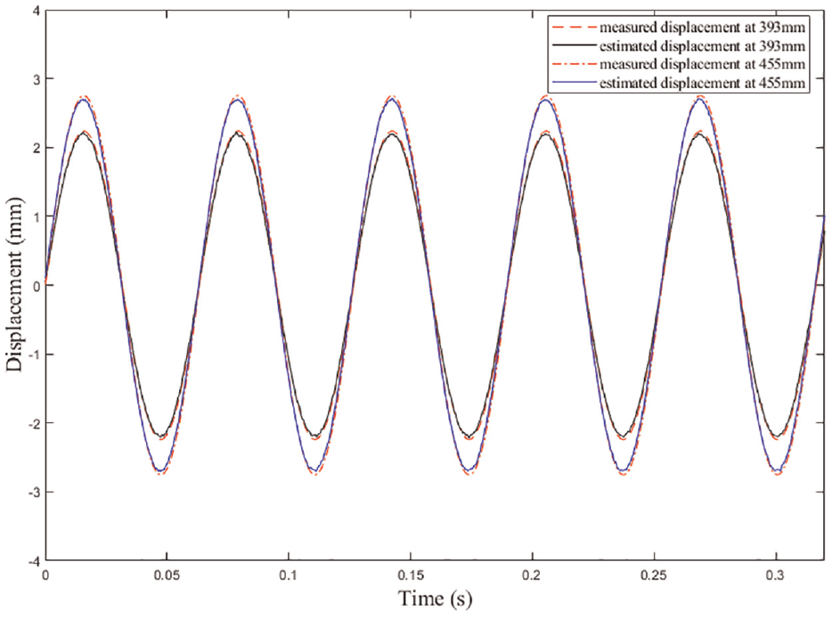
Vibration displacement measurement and estimation results.
Estimation errors of vibration monitoring results.
5.3. Vibration control tests
During wind tunnel tests, the airflow turbulence is a kind of broadband stochastic load. In order to simulate the real dynamic load in wind tunnel, the ground broadband excitation is performed by hammering the aircraft model in the pitch plane. Before vibration control tests, the control target g should be determined to calculate the initial values of
Control parameters and damping coefficients.
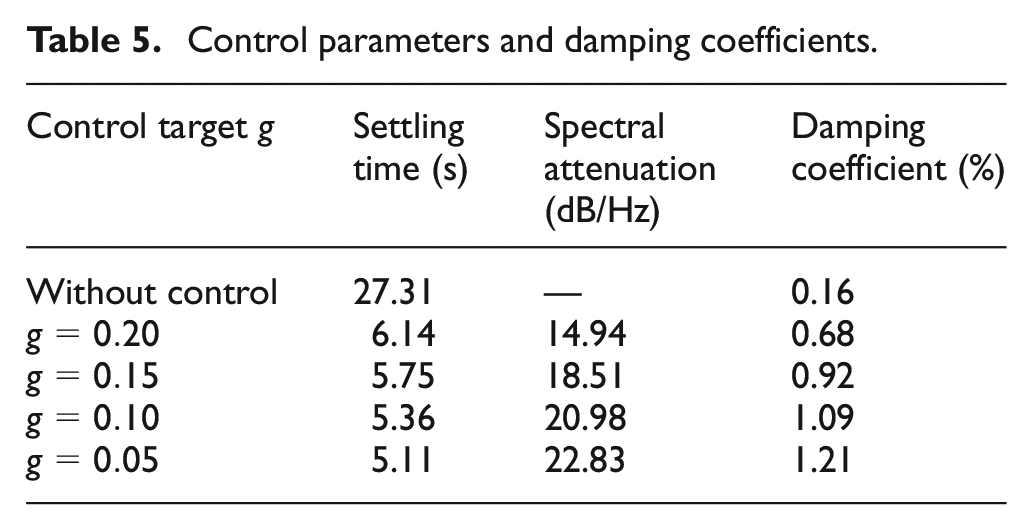
Then a series of ground impulse excitation tests are launched with active vibration suppression system on and off. The impulse response of the model-balance-sting system in time domain and frequency domain are shown in Figures 13 and 14, respectively. On the one hand, it is can be obvious seen that the vibration in the pitch direction lasts for over 27 s without controller, whereas the vibration is attenuated within 6 s with controller on. On the other hand, the Power Spectral Density (PSD) diagram shows that the spectrum is attenuated over 14 dB/Hz at the first resonance frequency. Meanwhile, Table 5 also shows that the damping ratio improves by more than seven times (from 0.16% to 1.21%), which is calculated by amplitude logarithmic decrement.
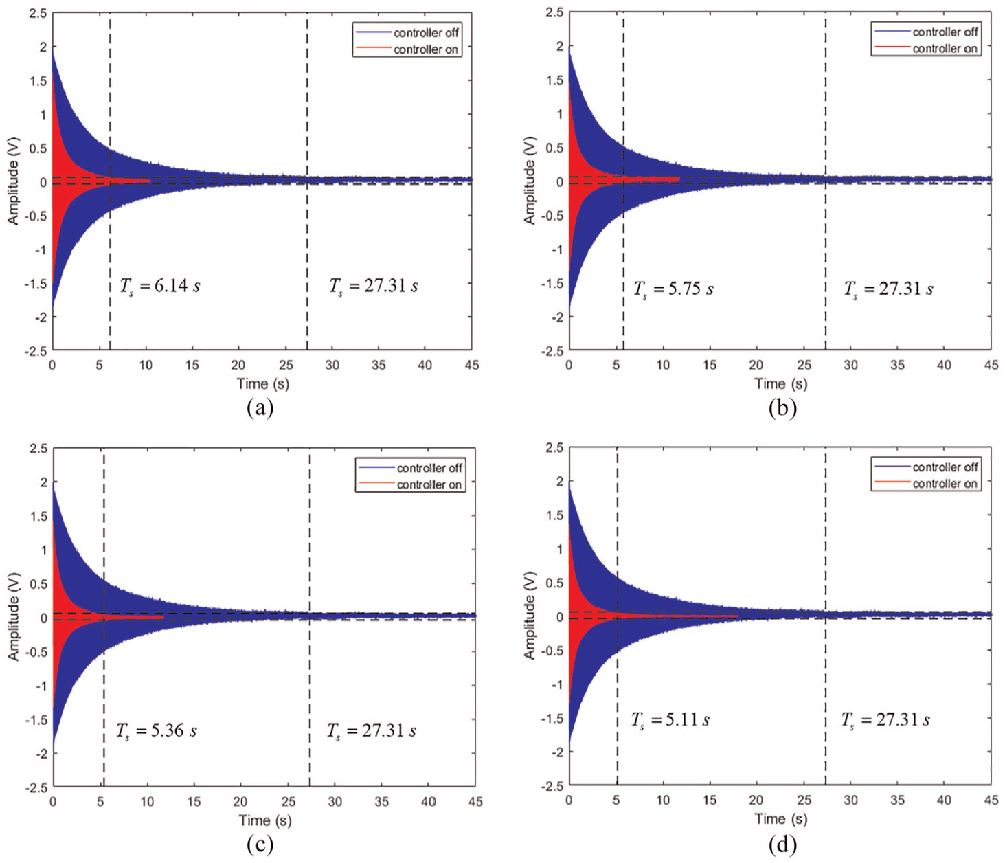
Time domain signals of impulse response with active vibration suppression system On and OFF: (a)
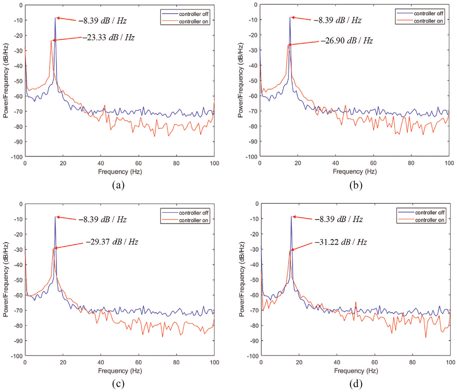
PSD of impulse response with active vibration suppression system On and OFF: (a)
6. Conclusions
Intelligent systems and structures have always been the research hotspot in aviation and aerospace fields. In this paper, a novel active damping vibration control system manipulated by two piezoelectric stack actuators is established for the vibration attenuation of the sting supporting system used in wind tunnel. On the premise of not changing the original structure of model-balance-sting, an intelligent active damping structure with piezoelectric stacks is designed. According to mechanical vibration theory, a simple and precise vibration monitoring method based on modal transformation algorithm is proposed to realize the measurement of vibration displacement. Moreover, a sensor placement optimization is conducted to improve the SNR of strain measurement and the estimation accuracy of the SDT matrix. Then by analyzing the dynamic characteristics of the active vibration suppression system, it is theoretically proved that this system has the ability to actively adjust damping. Furthermore, a self-adaptive BPNN-PD control method is proposed to suppress the first resonance frequency in the pitch plane under various testing conditions. The effectiveness of the control system is demonstrated by a series of verification tests in the laboratory. Results prove that system’s damping ratio can be dramatically improved by more than seven times and the settling time can also be shortened to less than 6 s, which indicates the validity of this intelligent vibration control system.
Footnotes
Acknowledgements
The authors would like to greatly appreciate reviewers’ helpful and constructive comments which substantially improve the quality of manuscript.
Declaration of conflicting interests
The author(s) declared no potential conflicts of interest with respect to the research, authorship, and/or publication of this article.
Funding
The author(s) disclosed receipt of the following financial support for the research, authorship, and/or publication of this article: This study was co-supported by the Aeronautical Science Foundation of China (Grant No. 20180952007), Foundation of National Key Laboratory on Ship Vibration and Noise (Grant No. 614220400307), the Research Fund of State Key Laboratory of Mechanics and Control of Mechanical Structures (MCMS-I-0520G01).