This article explores the nonlinear dynamical analysis and control of a DOF system that emulates the lateral vibration of an asymmetric rotor model under external, multi-parametric, and mixed excitation. The linear integral resonant controller () has been coupled to the rotor as an active damper through a magnetic actuator. The complete mathematical model, governing the nonlinear interaction among the rotor, controller, and actuator, is derived based on electromagnetic theory and the principle of solid mechanics. This results in a discontinuous DOF system coupled with two DOF systems, incorporating the rub-impact effect between the rotor and stator. The complicated mathematical model is investigated using analytical techniques, employing the perturbation method, and validated numerically through time response, basins of attraction, bifurcation diagrams, chaotic test, and Poincaré return map. The main findings indicate that the asymmetric system model may exhibit nonzero bistable forward whirling motion under external excitation. Additionally, it can whirl either forward or backward under multi-parametric excitation, besides the trivial stable solution. Furthermore, in the case of mixed excitation, the rotor displays nontrivial tristable solutions, with two corresponding to forward whirling orbits and the other one corresponding to backward whirling oscillation. These findings are validated through the establishment of different basins of attraction. Finally, the performance of the in mitigating rotor vibrations and averting nonlinear catastrophic bifurcations under various excitation conditions. Furthermore, the rotor’s dynamical behavior and stability are explored in the event of an abrupt failure of one of the connected controllers. The outcomes demonstrate that the proposed effectively eliminates dangerous nonlinearities, steering the system to respond akin to a linear system with controllable oscillation amplitudes. However, the sudden controller failure induces a local rub-impact effect, leading to a nonlocal quasiperiodic oscillation and restoring the dominance of the nonlinearities on the system’s response.
Nonlinear vibration manifests as an inevitable phenomenon in the rotating machinery, stemming from various factors that may act independently or concurrently. These factors encompass a spectrum of issues, such as (1) inherent nonlinearities of the shaft restoring force which induces the solution multiplicity and sensitivity of such rotor models to the initial conditions; (2) asymmetric restoring force in the case of non-circular shafts as well as the rotor cracks that appear as parametric or multi-parametric excitation forces in the equation governing the system dynamics; (3) imbalance, where the rotation of an unbalanced weight generates centrifugal forces that appear as external harmonic excitation leading to pronounced machine vibrations; (4) misalignment, observed when the axes of interconnected components, like a motor and pump, deviate from parallel, resulting in axial or radial vibrations, or a combination of both; (5) wear, exemplified by the traversal of bearing balls over a pitted roller bearings race, instigating machine vibrations; and (6) looseness, arising from the utilization of lax bearings or insecure attachment of the rotor to the mount, inducing substantial vibrations.
The various factors contributing to rotating machine vibrations have been addressed in the literature for over 50 years.1 Approximately two decades ago, Cveticanin2 delved into the free oscillations of a rotor model featuring cubic nonlinear restoring force. In his study, the author examined the sensitivity of the rotor to initial conditions using the Krylov-Bogolubov method. Based on the analysis, he reported that the rotor could oscillate along a straight line if initiated with initial bending, whereas a nonzero initial velocity could lead to circular whirling motion. Extensive discussions on rotor dynamics, considering both nonlinear restoring force and external excitation, have been presented.3–6 Adiletta et al.3 theoretically and experimentally explored the relationship between aperiodic oscillations and the nonlinear restoring force of a rotor model with adjustable stiffness coefficients. Experimental results indicated that changes in both stiffness and excitation amplitude could induce quasiperiodic oscillations. Ishida and Inoue4 examined the Jeffcott rotor model with minor gyroscopic effects, accounting for internal resonance conditions between forward and backward whirling modes. Theoretical and experimental findings revealed heightened complexity in resonance curves, the occurrence of nearly periodic motions, and substantial impacts from asymmetrical nonlinearity and gyroscopic effect. Yabuno et al.5 studied normal oscillation modes of a horizontally positioned rotor system with a cubic nonlinear restoring force. Through coordinate transformation, the authors derived an equivalent DOF system with quadratic and cubic nonlinearities. Theoretical and experimental investigations demonstrated that the system could experience localized and nonlocalized vibrations depending on disc eccentricity. They illustrated that the main cause of such oscillations is the small difference in natural frequencies between horizontal and vertical directions. In a recent study by Malgol et al,6 emphasis was placed on exploring the impact of hydrodynamic force generated by lubricant oil and gyroscopic force on a Jeffcott rotor model studied in Ref. 5. The principal conclusion drawn was that lubricant with high viscosity can efficiently attenuate system vibrations.
Different rotor models with asymmetric restoring forces have been explored extensively. Shahgholi and Khadem7 delved into the bifurcation behaviors of an asymmetric continuous rotor model subjected to external and parametric excitations. The multiple scales method was applied to derive frequency response equations governing the amplitude of first-mode oscillation. They reported that bifurcation in the asymmetrical shaft occurs at speeds either above or below the linear forward frequency. Srinath et al.8,9 examined the stability of the asymmetrical rotor, treating it as both a continuous and lumped parameters model. The authors considered the systems as multi-degree of freedom Mathieu equations, utilizing perturbation analysis and Floquet theory. They reported stability conditions for various system parameters. Yi et al.10 discussed the dynamics of a rotor system with both disc and shaft featuring asymmetric cross-sections and subjected to periodic base excitations. They concluded that both the response spectra and external resonances undergo substantial alterations when considering the periodic excitation of the base. In Refs. 11, Bavi et al. investigated the behaviors of an asymmetric thin-walled unbalanced rotating shaft. In Ref. [12] they extended their study to the same model as in Ref. [11] incorporating gyroscopic motion while ignoring the unbalanced effect.
Rub-impact occurrences between rotating parts and the housing arise as a consequence of strong oscillations triggered by one or more of the previously mentioned factors. This rub-impact effect has the potential to induce intricate responses, including quasiperiodic, chaotic behavior, or even rotating machinery damage.13–19 Chang-Jian and Chen13 investigated the influence of the rub-impact effect on a rotor model supported by oil-film short bearings, incorporating support nonlinearities into the studied system. They reported that the rotor may experience chaotic oscillation as a result of the rub-impact effect. The dynamics of a rotor suspended via oil-film journal bearings with the introduction of rub-impact force is discussed by Wang et al,14 revealing the complex dynamics of the system due to changes in either damping or angular speed. Khanlo et al.15,16 examined the dynamics of a rotor system by modeling it as a flexible continuous beam. In their analysis, the authors considered both the rub-impact and Coriolis effects. Their findings indicated that the system could display rub-impact behavior at low-speed ratios, attributed to the combined influence of Coriolis and centrifugal forces. In a comprehensive theoretical and experimental exploration, Hu et al.17 investigated the rub-impact effect on the dynamics of an asymmetrical two-disc rotor supported by oil-film bearings. The key findings indicated that increasing either stator stiffness or eccentricity led to a reduction in the whirl of the oil-film, while the oil-whip phenomenon was not affected. Saeed et al.18,19 discussed the dynamics of an asymmetric rotor model featuring either quadratic and cubic nonlinear restoring force or cubic only, under the influence of rub-impact and active control. The primary findings indicated that rub-impact could lead to period-n, quasiperiodic, or chaotic motion, contingent on angular speed, impact stiffness, and dynamic friction. Nevertheless, the authors reported that adjusting the control parameters has the potential to reduce oscillation amplitude, thereby eliminating the undesired impact of rub-impact.
Vibration, as an inherent and unavoidable phenomenon, has the potential to impact the durability, reliability, and efficiency of rotating machinery. Scientific research predominantly focuses on developing rotating machinery that exhibits heightened resilience to significant vibrations, achievable through either passive or active control methods. Passive control options for rotating machines include tuned mass dampers,20 nonlinear energy sinks,21,22 and high-static low-dynamic damping absorbers,23 each with its own limitations. Active vibration control, on the other hand, is realized through active magnetic bearings, allowing the application of control forces through electromagnetic attraction without physical contact. This approach employs advanced control techniques.24 Despite extensive studies on the dynamics of magnetic actuators supporting rotating discs in configurations like four-pole,25 six-pole,26,27 eight-pole,28–32 12-pole,33,34 and 16-pole systems,35,36 Ishida and Inoue37 may be the first to apply the concept of semi-active vibration control in rotating machines. They utilized a four-pole system as a push-pull vibration absorber to mitigate lateral oscillation in a vertically positioned nonlinear rotor model. Subsequently, Saeed et al.38,39 employed eight-pole magnetic bearings as active actuators, applying control actions to the rotor system using advanced control algorithms. In their study,38 the authors investigated the effectiveness of a control algorithm through an eight-pole actuator to reduce lateral oscillations in an unbalanced rotor model having a cubic nonlinear restoring force. In Ref. [39] vibration control of an unbalanced rotor model featuring both cubic and quadratic restoring forces was addressed using a proportional integral resonant control and an eight-pole actuator.
The present study marks the initial effort to evaluate the efficacy of the integrated into a magnetic actuator as an active damper for controlling the bifurcation characteristics of an asymmetric rotor model and mitigating undesired vibrations arising from external, multi-parametric, or simultaneous excitations. Consequently, the entire system model has been formulated as a DOF system that simulates rotor vibrations coupled with two DOF systems governing dynamics, accounting for rub-impact between the actuator and the rotor. Utilizing a generalized coordinate system, the entire system model is normalized and subsequently analyzed employing asymptotic analysis and various numerical techniques. The performance of the has been investigated under external, multi-parametric, and simultaneous excitations. Both analytical assessments and corresponding numerical simulations affirmed the robust efficiency of the as an active damper, capable of eliminating complex angular-speed-response curves and suppressing multistability characteristics under different excitation conditions. Finally, the rub-impact effect in the event of a sudden controller failure has been conducted. The results indicate that the rotor may undergo a local rub-impact force, resulting in a nonlocal quasiperiodic oscillation. Additionally, the nonlinearities resurface to dominate the rotor response.
Mathematical modeling
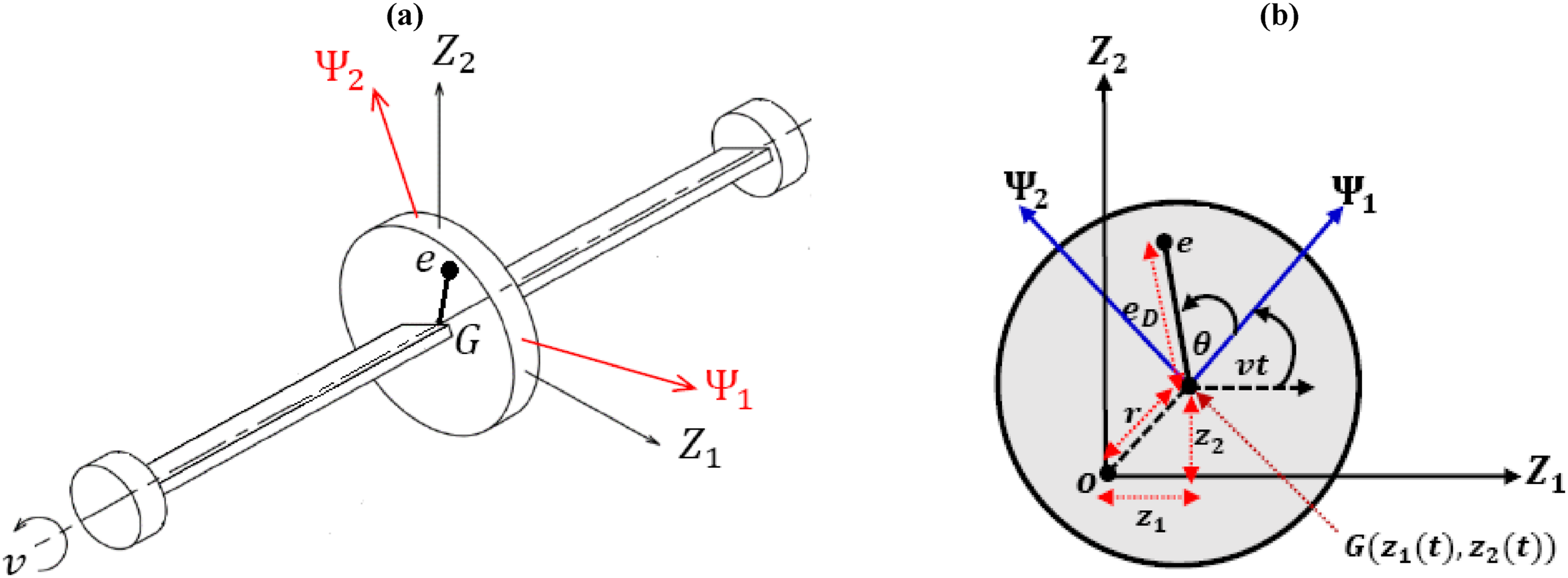
The rotor under study is modeled as a Jeffcott system with lumped parameters. This system comprises a rotating disc with a mass of (in ) positioned at the midpoint of an asymmetric elastic shaft with a rectangular cross-sectional area. As shown in Figure 1(a), the rotor is assumed to rotate anticlockwise with an angular velocity of (in ). Additionally, the rotor is considered to exhibit instantaneous lateral oscillations and in the inertial reference frame . Meanwhile, represents a rotational coordinate system that rotates at the same angular speed as the rotor. Accordingly, the differential equations governing the undesired lateral oscillations of the rotor, and , can be expressed as follows18,40
where and represent the velocities and accelerations of the rotor, respectively. The terms and are the damping coefficients in the and directions, respectively. signifies the rotor’s eccentricity, which is the distance between the disc’s geometric center and its centroid . The angle is defined as the angle between the and axes, as illustrated in Figure 1(b). (where and ) are the asymmetric shaft restoring forces, control forces, and rub-impact forces, respectively, as will be modeled in the subsequent sections.
(a) Jeffcott rotor with an asymmetrical rotating shaft, and (b) rotating disc with lateral displacements and .
Asymmetric restoring forces and
Given that the considered shaft has an asymmetric rectangular cross-section, it is posited that the shaft’s restoring force in the direction of its narrower thickness is less than that in the direction of its greater thickness. Let the axis be directed along the narrower thickness and is directed along the greater thickness. Accordingly, one can define the shaft restoring forces in the rotational reference frame as follows19
where and denote the oscillation displacements in and directions, respectively, and are the linear and nonlinear stiffness of the rotor in and directions, while and are the stiffness asymmetry as Figure 1(a) implies. The relation between the displacements and can be obtained as follows:
In addition, the Cartesian components in the direction and in the direction of the shaft restoring forces can be expressed in terms of the rotational restoring forces and respectively, as follows
Substituting equations (2) and (3) into equation (4), one can obtain and in terms of the Cartesian displacements and as follows
Control forces and
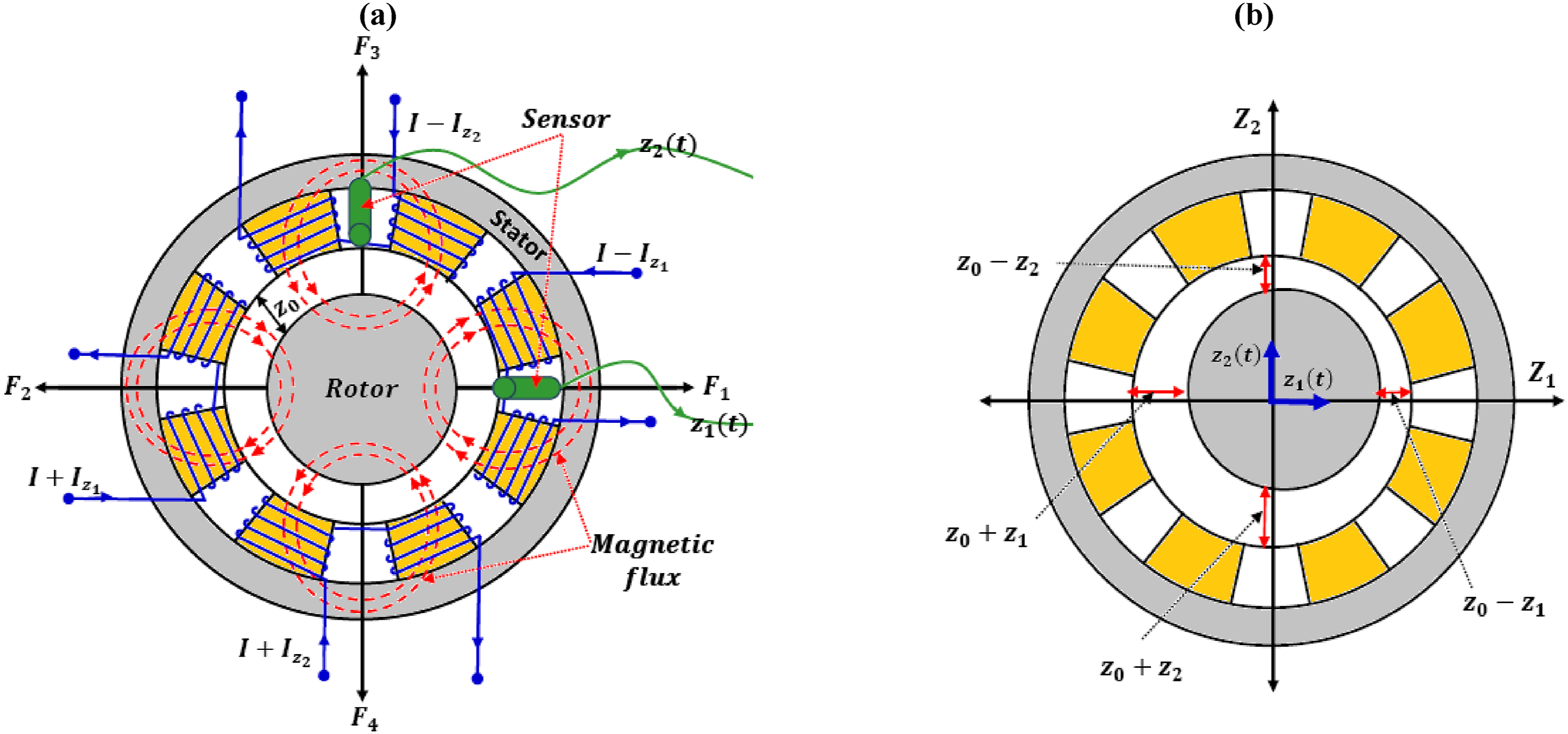
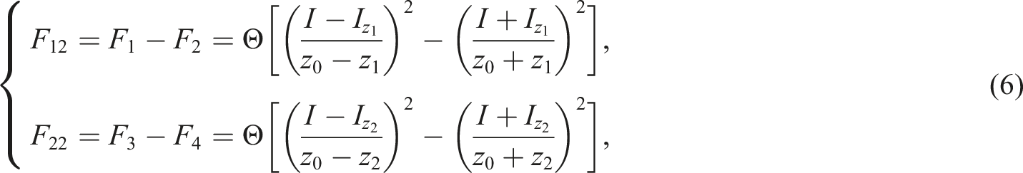
To suppress the undesired instantaneous oscillations and of the rotor, an active control strategy is introduced. This strategy is designed to counteract parametric and forced oscillations arising from both the disc’s eccentricity and the shaft’s asymmetry. The proposed control system incorporates four electromagnetic poles. These poles are electrically energized to apply a push-pull control action in both the and directions, following a specific control law as depicted in Figure 2(a). Of these poles, the two horizontal ones target the reduction of the unwanted vibration , whereas the two vertical poles aim to diminish the undesired oscillation . Assuming represents the nominal clearance between the rotor and the four-pole stator, the dynamic clearance related to the four poles, given rotor displacements and , can be articulated as and . These clearances are further visualized in Figure 2(b). Building on electromagnetic theory,41 the four-pole system can generate attractive forces represented as: and . Consequently, the net control forces in the direction and in the direction can be derived as
where is the electromagnetic coupling constant, represents a constant electric current applied to all the magnetic poles, and and are the control currents in the and directions, respectively. These currents are used to regulate system oscillations based on the proposed control algorithm. The control currents are designed to follow the algorithm. Therefore, and are expressed as follows
where and are the linear control gains. It is well known that the states and of the are governed by a first-order dynamical system excited by the main system states (i.e., and ). So, the equation governing and can be written as follows39
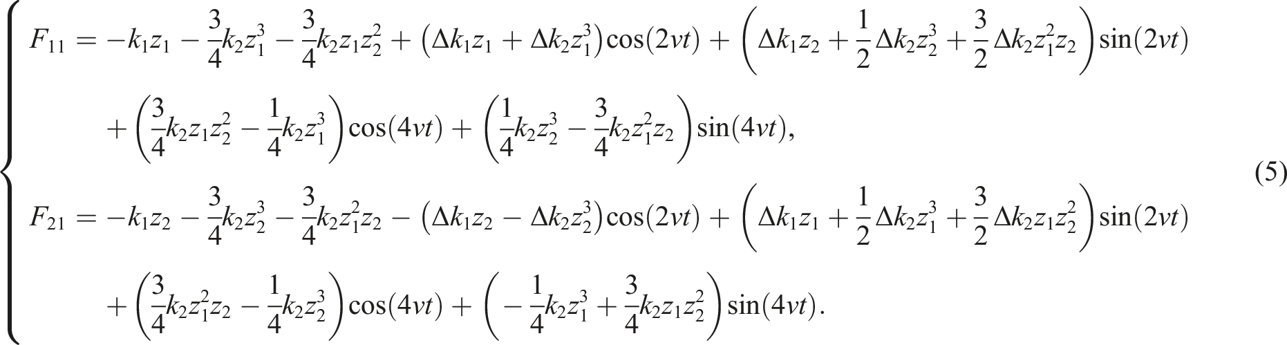
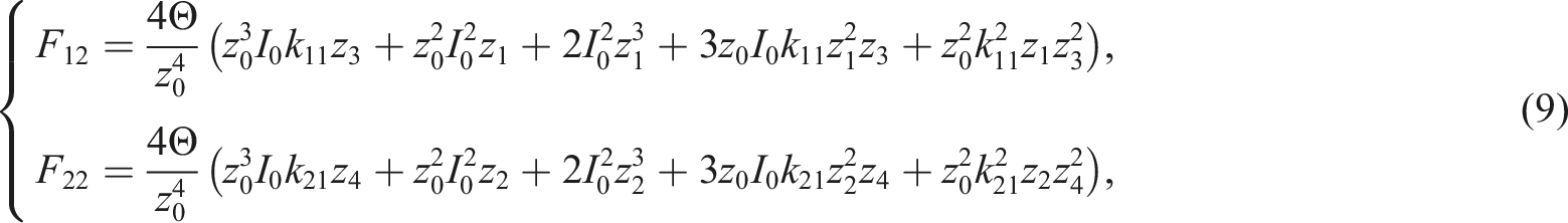
where , and are constants that represent the internal and feedback gains of the . Substituting equation (7) into equation (6), with expanding the resulting equations using the third-order Maclaurin series, yields the control forces
Asymmetric rotor equipped with four-pole magnetic actuator: (a) Rotor-stator at the general position, and (b) Rotor-stator at the nominal position.
Rub-impact forces and
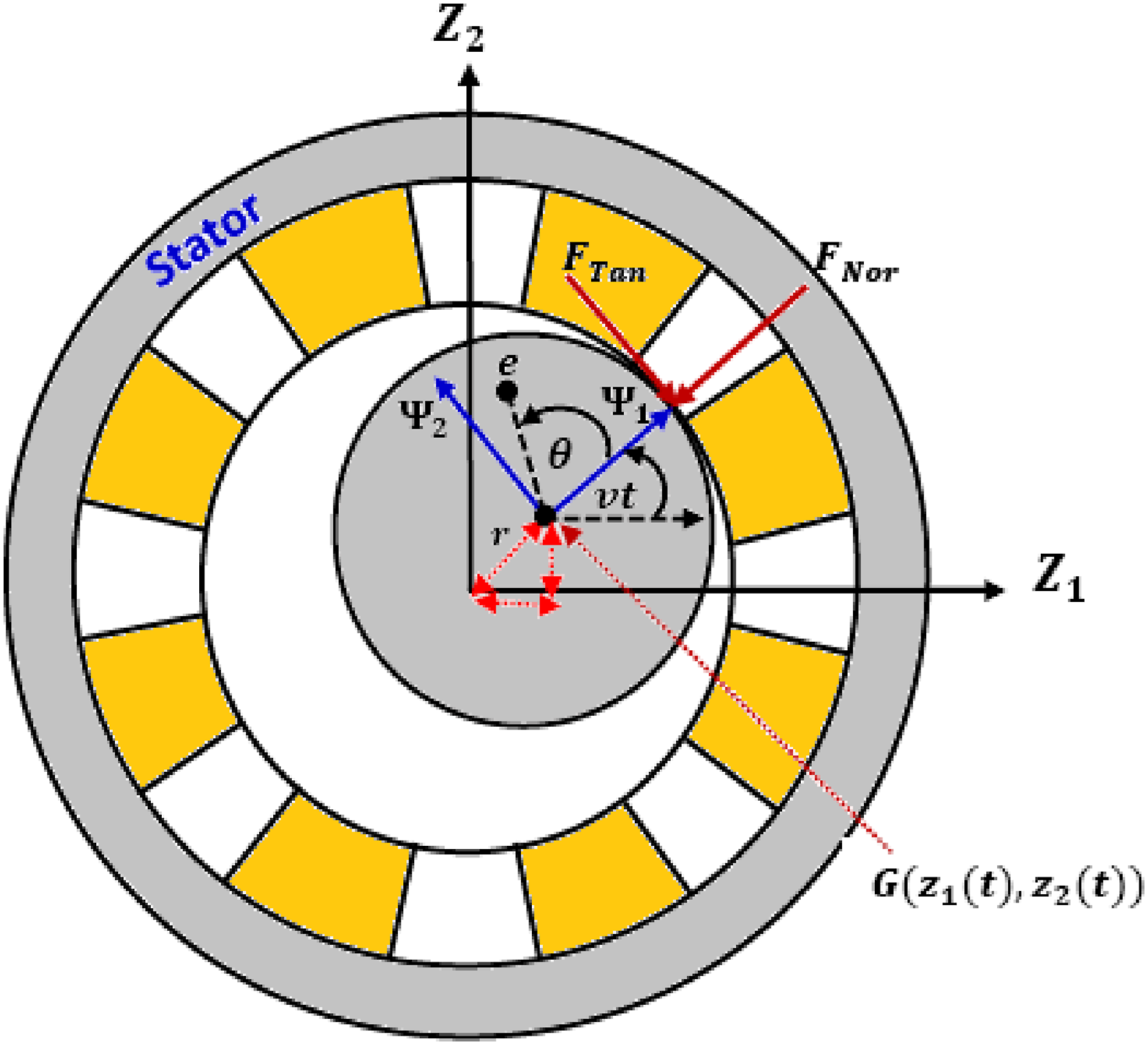
The primary objective of the , as introduced above, is to minimize rotor oscillations in both the and directions, irrespective of the excitation sources. However, if the control forces and fail to maintain and/or below the nominal rotor-stator clearance as depicted in Figure 2(a), it will lead to impact and/or rub forces between the rotor and stator. In such cases, the normal impact force and the rub tangential force will arise at the rotor-stator interface, as shown in Figure 3. These forces can be expressed as follows13–19
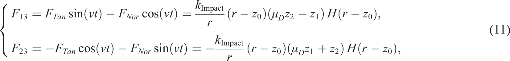
where is the impact linear stiffness coefficient, is the instantaneous radial displacement of the rotating disc, is the Heaviside function, is the frictional coefficient between the internal surface of the housing and the outer surface of the rotor. Based on the geometry of Figure3, the components of and in and directions (i.e., and ) can be written as follows13–19
where .
Asymmetric rotor equipped with magnetic actuator in rotor-stator rub-impact mode.
Full system model, normalized equations, and approximate solution
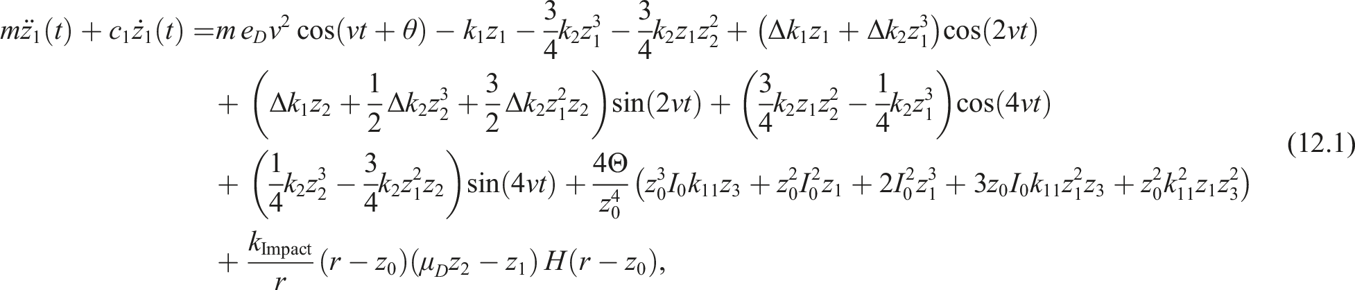
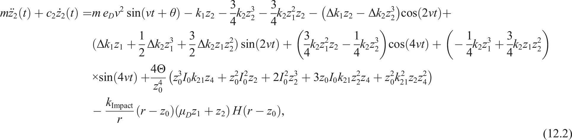
Now, Substituting equations (5), (9), and (11) into equation (1), yields the whole controlled asymmetric rotor model including the rotor-stator rub-impact effect as:
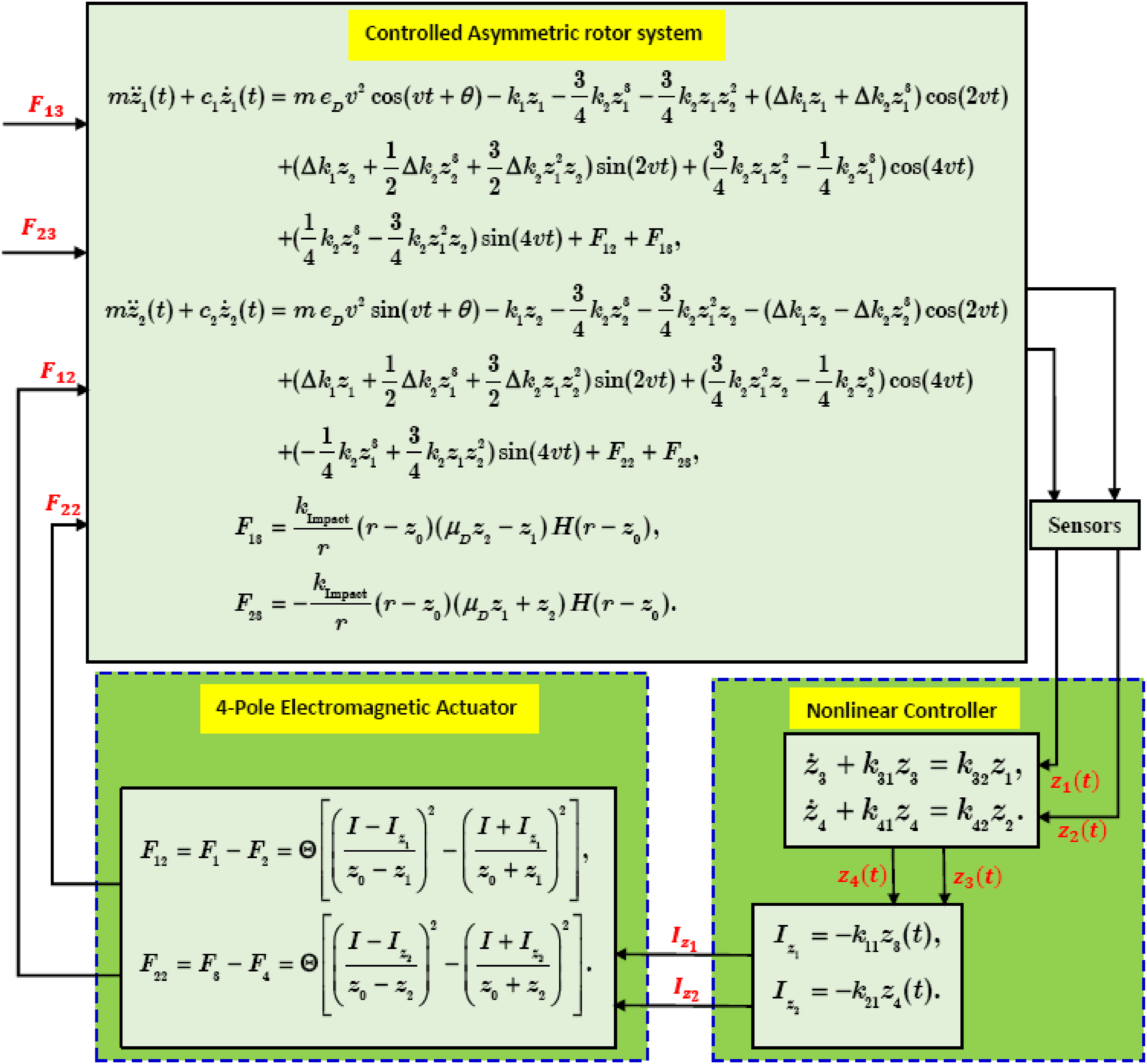
The block diagram that shows the flow of the introduced control process is detailed in Figure (4). Two sensors, as depicted in Figure 2(a), are used to measure the rotor’s undesired instantaneous displacements, displacements and . These displacements are fed into the , which then calculates the control currents and based on the designed control gains (i.e., , and ). Finally, the generated electrical currents and are applied to the four-pole actuators to suppress the rotor oscillations in the and directions via the push-pull control forces and .
Block diagrams to show the sequential execution of the introduced control method.
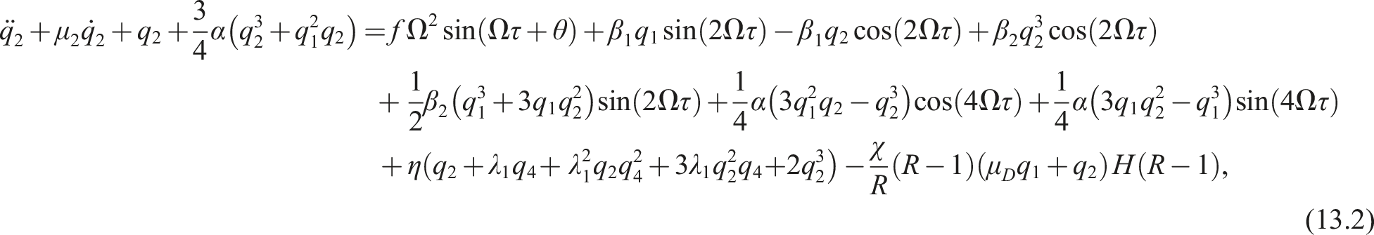
To investigate the nonlinear dynamics of the entire system as described by equations (12.1) to (12.4), we normalized these equations in general form using dimensionless parameters , and (where is the rotor’s natural frequency). Introducing these dimensionless parameters into equations (12.1) to (12.4), yields the following normalized system
where and . Referring to the above-normalized equations governing the controlled asymmetric rotor, and represent the rotor dimensionless displacements in the and directions, respectively. Similarly, and represent the displacements of the proposed . Additionally, and denote the normalized control gains. Moreover, and are the internal feedback gains, while and represent the feedback gains. Accordingly, to explore the performance of the proposed in mitigating the rotor external, multi-parametric, and mixed oscillations, an analytic solution for equations (13.1) to (13.4) is sought using perturbation analysis when neglecting the rub-impact force (i.e., ) as follows42
where is a book-keeping perturbation parameter, and . In terms of and , the ordinary derivatives and may be expressed as follows
To follow multiple scales solution procedure, the system parameters should be scaled such that:
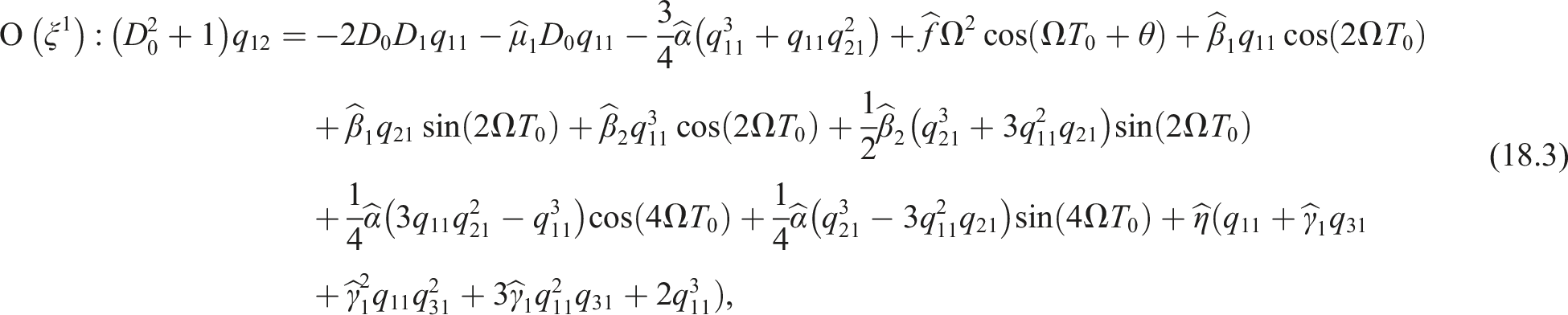
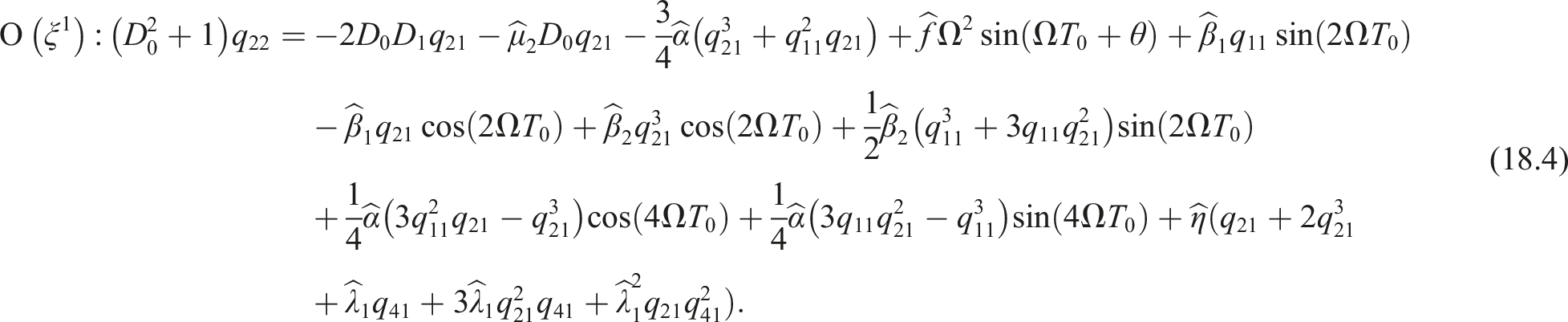
Now, substituting equations (14.1) to (16) into equations (13.1) to (13.4), neglecting the rub-impact effect by setting , yields.
The full solution of equations (17.1), (17.2), (18.1), and (18.2) can be obtained, respectively, as follows
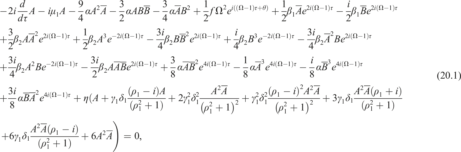
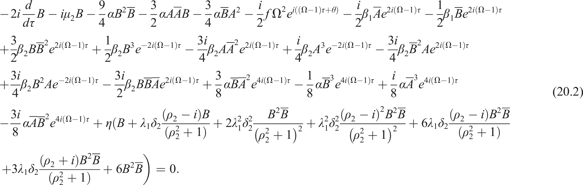
where . The coefficients and are unknown and will be defined later. Additionally, and are the conjugate functions of and , respectively. By substituting equations (19.1) to (19.4) into equations (18.3) and (18.4), we obtain the following solvability conditions at the primary resonance (i.e., ):
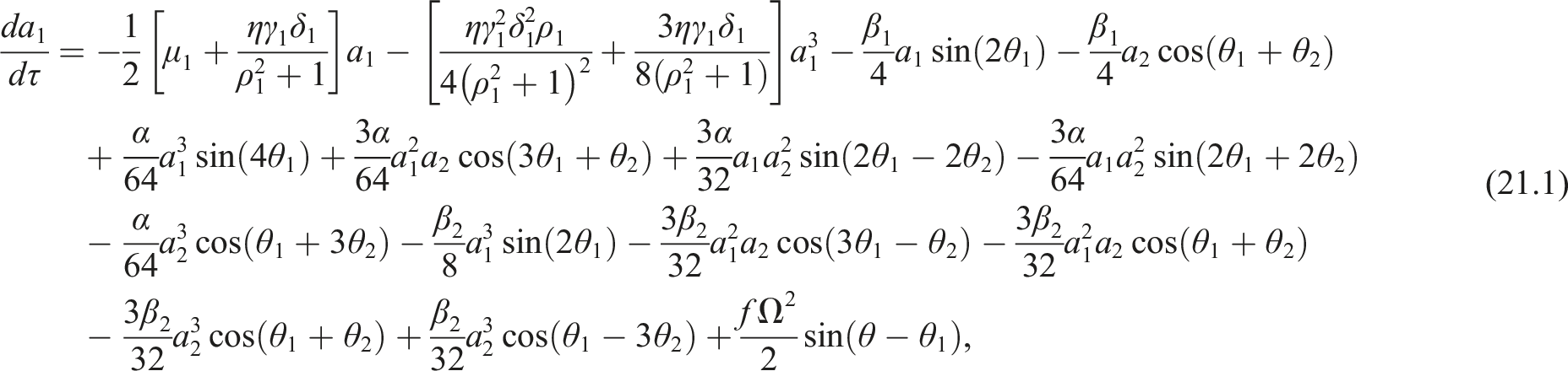
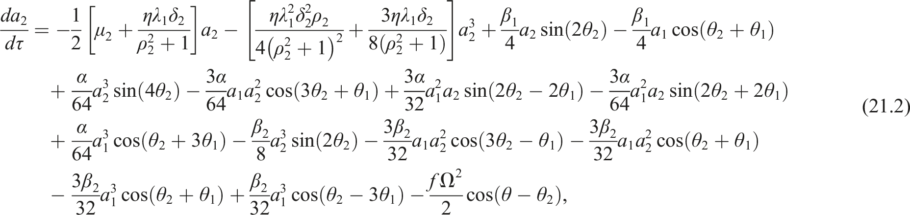
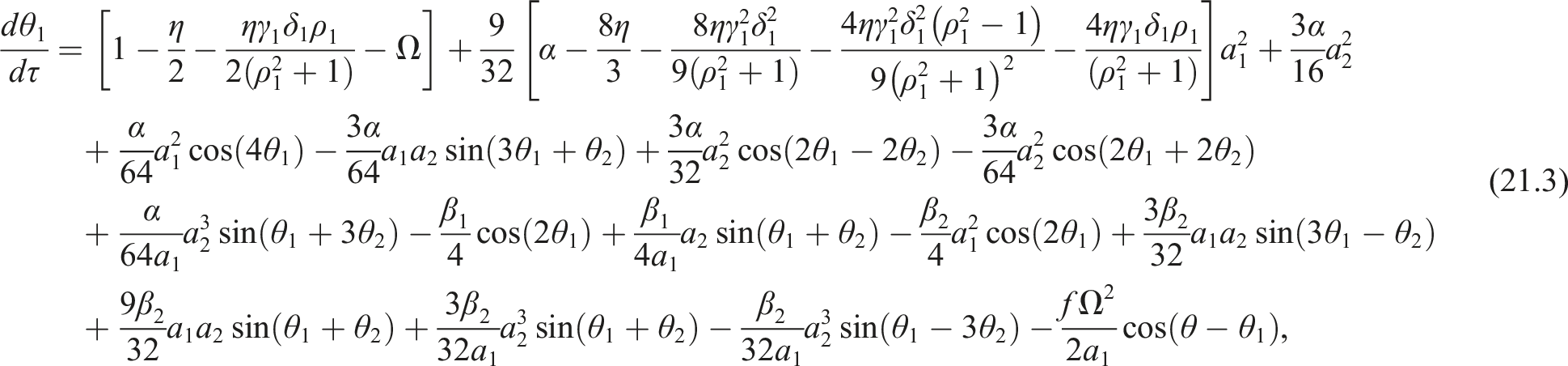
Now, by substituting the polar forms and into equation (20), we can derive the following amplitude-phase equations42
where and . It is evident from equations (21.1) and (21.2) that the linear damping coefficients and of the controlled rotor have been modified to the equivalent linear damping coefficients and . Additionally, the cubic nonlinear damping coefficients and resulting from the coupled control added to the system are such that and . Furthermore, equations (21.3) and (21.4) illustrate that the system’s normalized natural frequencies (i.e., ) have been modified to and . Moreover, the cubic stiffness of the rotor after control has been modified to and . Accordingly, based on the selected control gains ( and ), one can control the damping and stiffness of the system.34 Now, by substituting equations (19.1) to (19.4) into equations (14.1) and (14.2), one can express the periodic solution of equations (13.1) to (13.4) as follows:
where , and .
Nonlinear algebraic system and bifurcation analysis
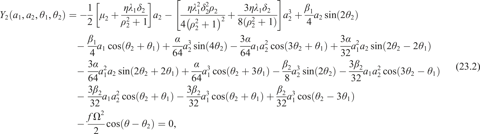
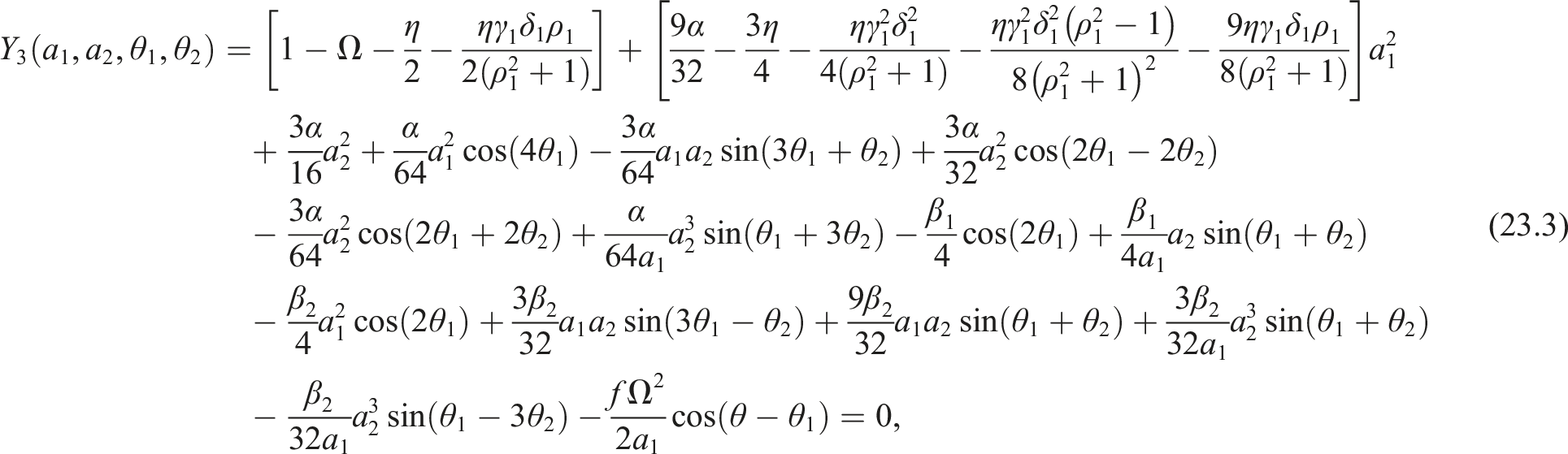
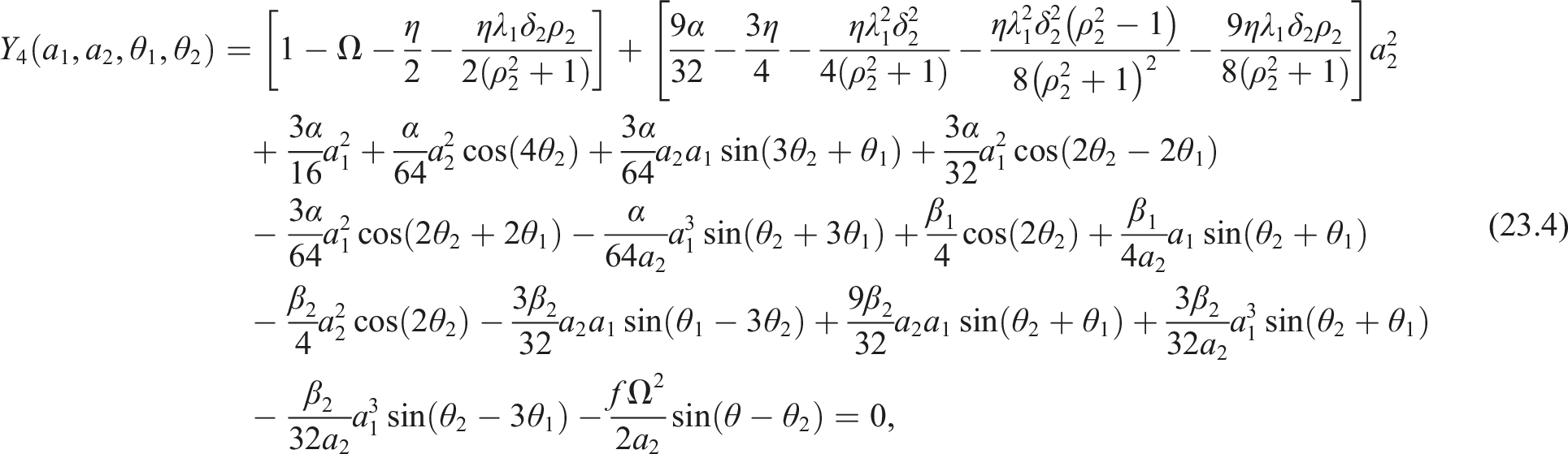
Based on equations (22.1) to (22.4), and represent the oscillation amplitudes of the system in the and directions, respectively. Meanwhile, the amplitudes of the controllers, and , are scalar multiples of and , respectively. Furthermore, the instantaneous evolution of and as a function of various parameters (i.e., ) is governed by the autonomous system described by equations (21.1) to (21.4). Consequently, the bifurcation characteristic of and can be analyzed using the nonlinear algebraic system obtained by setting and to zero in equations (21.1) to (21.4) as follows
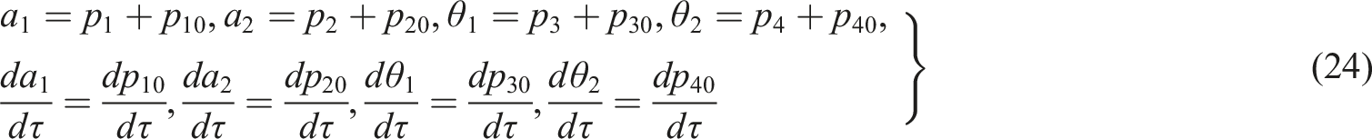
Solving equations (23.1) to (23.4) by the predictor-corrector arch-length algorithm,43 we can derive the various response curves, which are detailed in the next section. Additionally, the stability of the solution where , can be assessed using the linear system corresponding to equations (21.1) to (21.4). Let’s assume the solution for is and . Additionally, suppose , and represent small infinitesimal increments of and , respectively. Accordingly, we can express the perturbed solution of equations (23.1) to (23.4) as follows
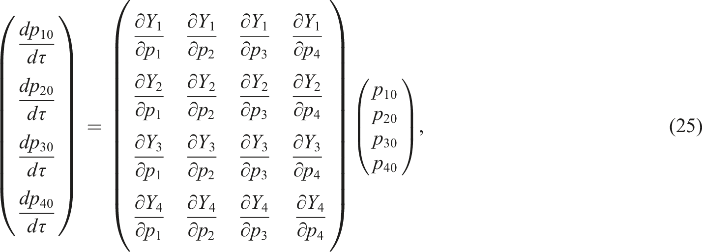
Substituting equation (24) into equations (21.1) to (21.4) with linearizing the resulting nonlinear system about the equilibrium point (), one gets the following variational system44
Consequently, the solution stability of equations (23.1) to (23.4), can be checked based on the eigenvalues of equation (25).
Results and discussions
Based on the preceding analysis, this section delves into the system dynamics and assesses the feasibility of the proposed controller. By solving equations (23.1) to (23.4) for parameters such as and , one can anticipate the oscillation amplitudes ( and ) of the asymmetric rotor discussed in this study. Furthermore, the stability of these solutions can be explored through the linear model given by equation (25), where in all incoming bifurcation diagrams the solid line refers to the stable solution, and the dotted line indicates the unstable solution. Moreover, to distinguish the whirling motion in either forward or backward directions, one can rewrite equations (22.1) and (22.2) using cosine and sine functions, as follows:
where and . An ellipse is the locus of the point in the complex plane, which can be decomposed into forward and backward precession circles such that
where and are the positive and negative precession components, respectively. Accordingly, the positive () and negative () precession amplitudes can be expressed as follows45
Substituting and into equations (28.1) and (28.2), yields
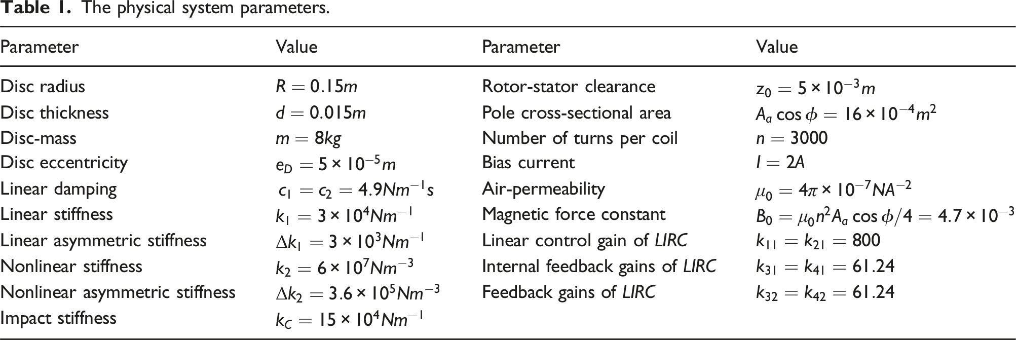
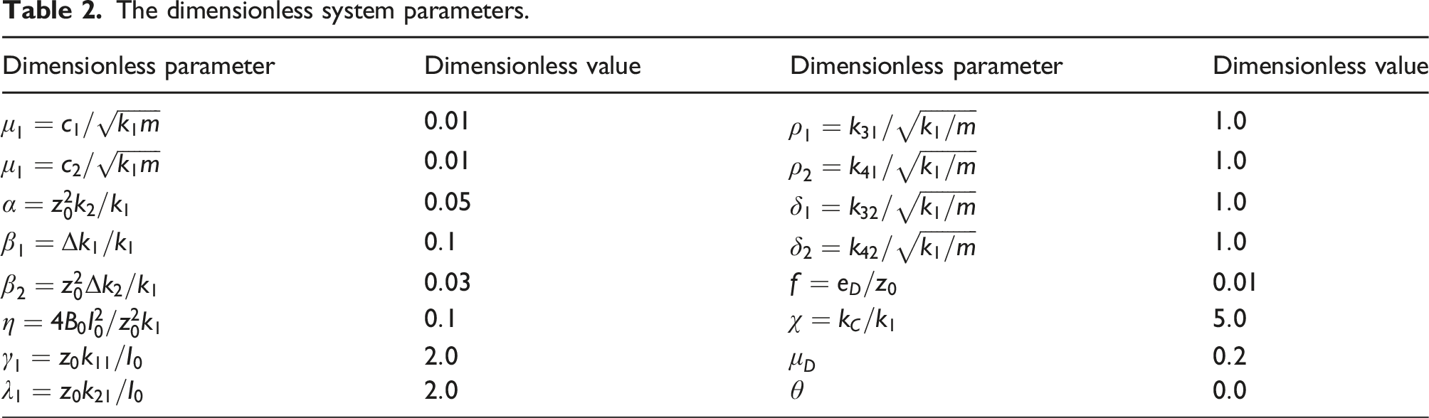
According to equations (29.1) and (29.2), the system exhibits forward whirling motion when , and it whirls backward when .45Table 1 presents the actual parameter values for the examined rotor-actuator and the controller gains (See Ref. 19). Additionally, the associated dimensionless parameter values have been computed as given in Table 2. The system’s nonlinear dynamics are examined at 1:1 internal resonance when the rotor undergoes primary, parametric, and mixed excitation within this work. External exciation section delves into the system dynamics during 1:1 internal resonance under primary external excitations. Parametric excitation section focuses on the rotor’s oscillation at 1:1 internal resonance with only multi-parametric excitation. Finally, mixed excitations section investigates the impact of combined external and multi-parametric excitations at a 1:1 internal resonance.
The physical system parameters.
Parameter
Value
Parameter
Value
Disc radius
Rotor-stator clearance
Disc thickness
Pole cross-sectional area
Disc-mass
Number of turns per coil
Disc eccentricity
Bias current
Linear damping
Air-permeability
Linear stiffness
Magnetic force constant
Linear asymmetric stiffness
Linear control gain of
Nonlinear stiffness
Internal feedback gains of
Nonlinear asymmetric stiffness
Feedback gains of
Impact stiffness
The dimensionless system parameters.
Dimensionless parameter
Dimensionless value
Dimensionless parameter
Dimensionless value
External excitation
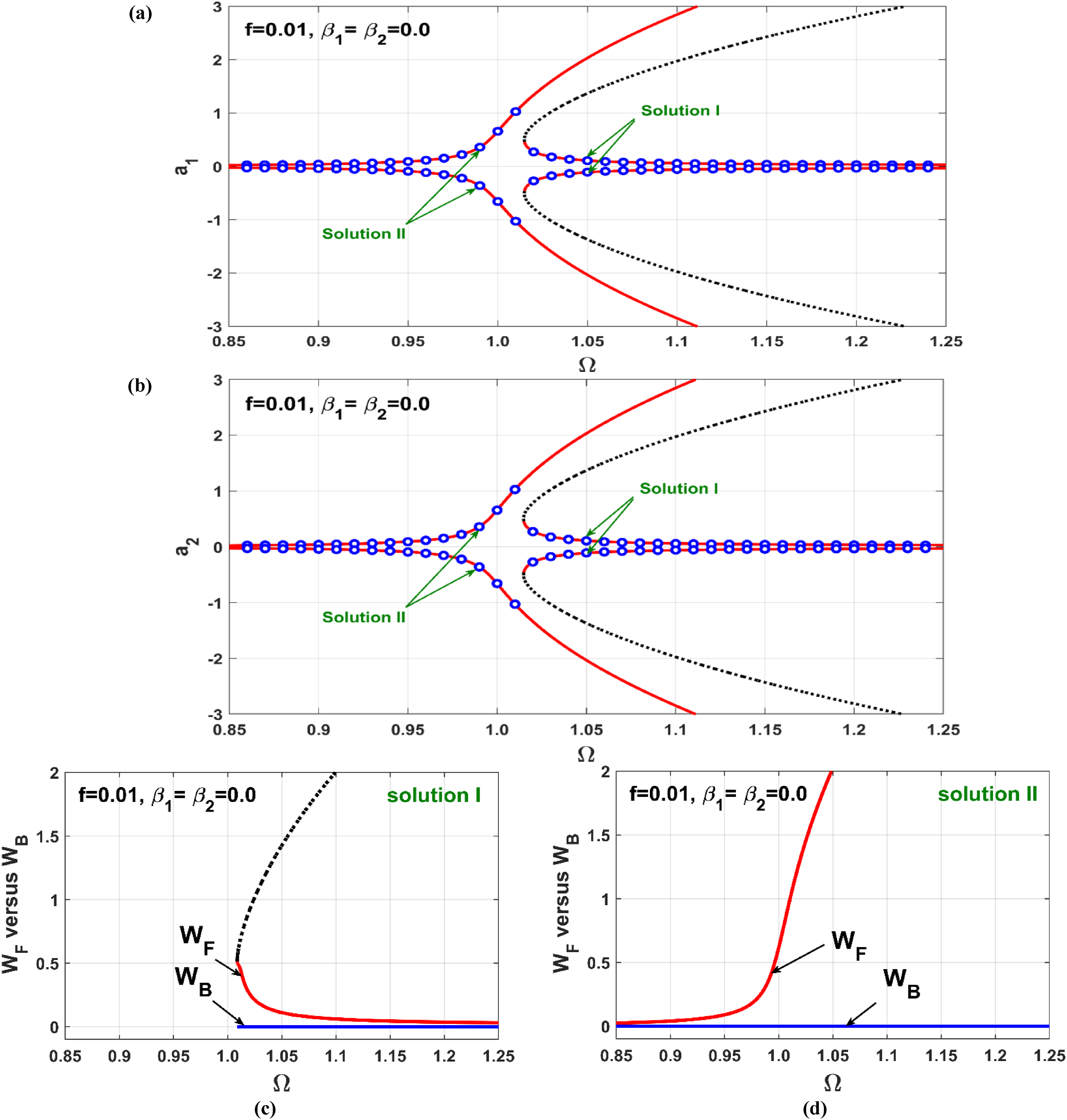
The nonlinear oscillations of the rotor system, when neglecting shaft stiffness asymmetry (i.e., and ), are discussed in this section. Figure 5 illustrates the oscillation amplitudes of the uncontrolled rotor (i.e., ) versus the angular speed close to the resonance condition (i.e., ). It is evident that the system exhibits symmetric oscillation in both and directions. Additionally, the system behaves like a Duffing oscillator with hard spring characteristics due to the nonlinear restoring force of the rotor shaft. This means the rotor can exhibit one of two oscillation amplitudes depending on its initial position at specific rotational speeds. For instance, at , the rotor system presents bistable solutions (i.e., Solution I and Solution II as shown in Figures 5(a) and 5(b). The system will manifest one of these solutions based on the initial values of and .
(a, b) Uncontrolled vibration amplitudes and versus the angular velocity when , (c) forward whirling on Solution I branch because , (d) forward whirling on Solution II branch because .
The bifurcation diagram presented in Figure 5(a) and (b) is derived from an approximate analysis, specifically equations (23.1) to (23.4). To validate these approximate solutions, numerical validations are marked as hollow blue circles in the same figure. These numerical results were generated by integrating the rotor’s temporal equations, equations (13.1) and (13.2), using MATLAB’s built-in solver ODE15s with parameters set at and . The bifurcation parameter was discretized over the interval using a constant step-size , where for . Initially, equations (13.1) and (13.2) were numerically integrated at with zero initial conditions. After reaching the steady-state temporal oscillation (i.e., and ), the vibration amplitudes and at were determined as the maximum values of and , respectively. Subsequently, was incremented to . The steady-state temporal oscillation was then computed again at as and , using the final states from the previous step (i.e., and ) as initial conditions. This process continued until at which the oscillation amplitudes were calculated as and using the initial conditions and . The oscillation amplitudes were then plotted as and against using small hollow circles for all . By analyzing Figure 5, it is evident that there is a strong correspondence between the numerical integrations and the analytical approximate solutions. In addition, to illustrate the direction of rotor whirling, whether forward or backward corresponding to Solution I and Solution II branches, the components and given by equations (29.1) and (29.2) are plotted in Figure 5(c) and (d). These figures demonstrate that the system exhibits exclusively forward whirling motion, regardless of whether the rotor follows Solution I or Solution II branches, where along the axis.
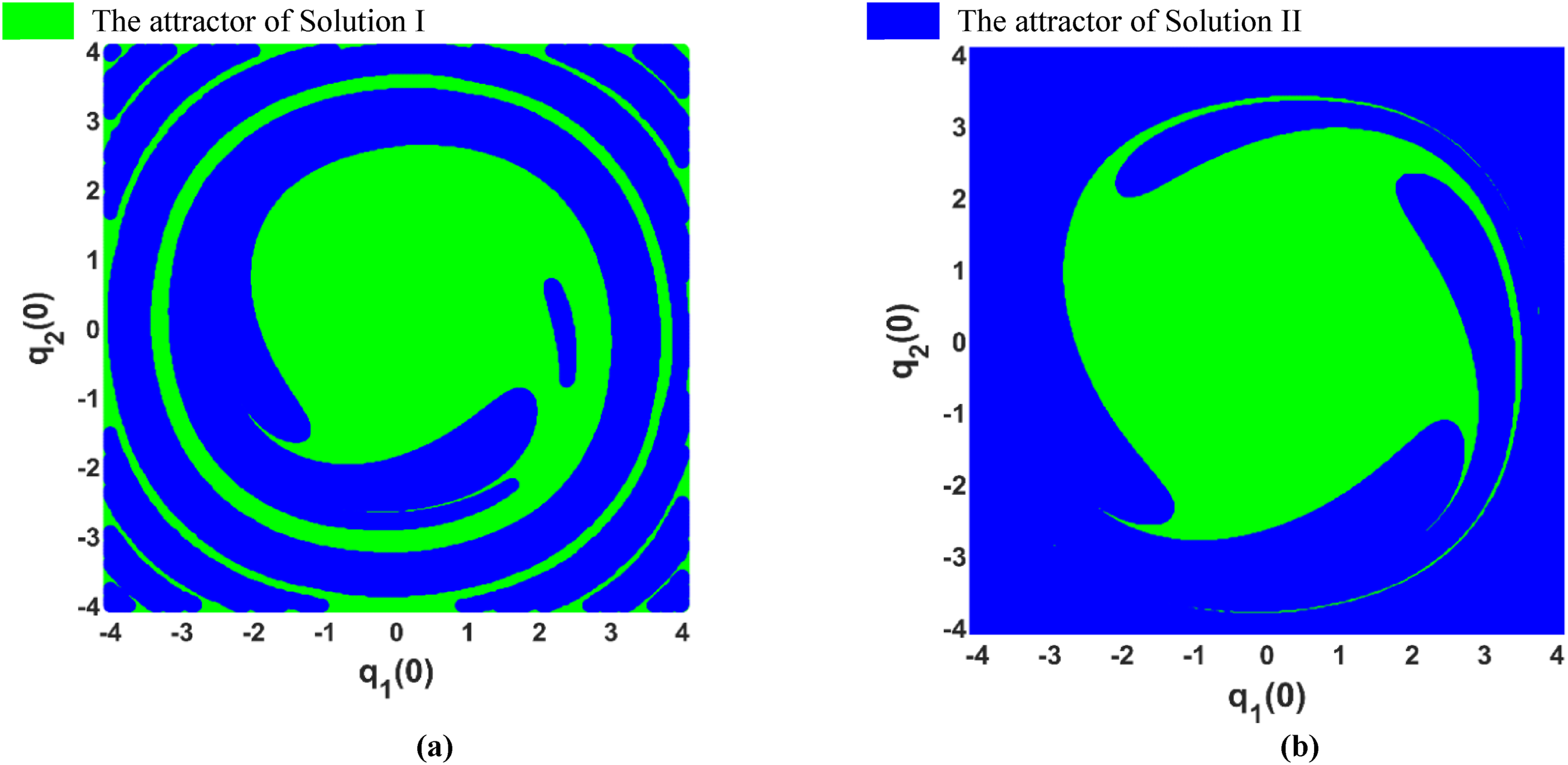
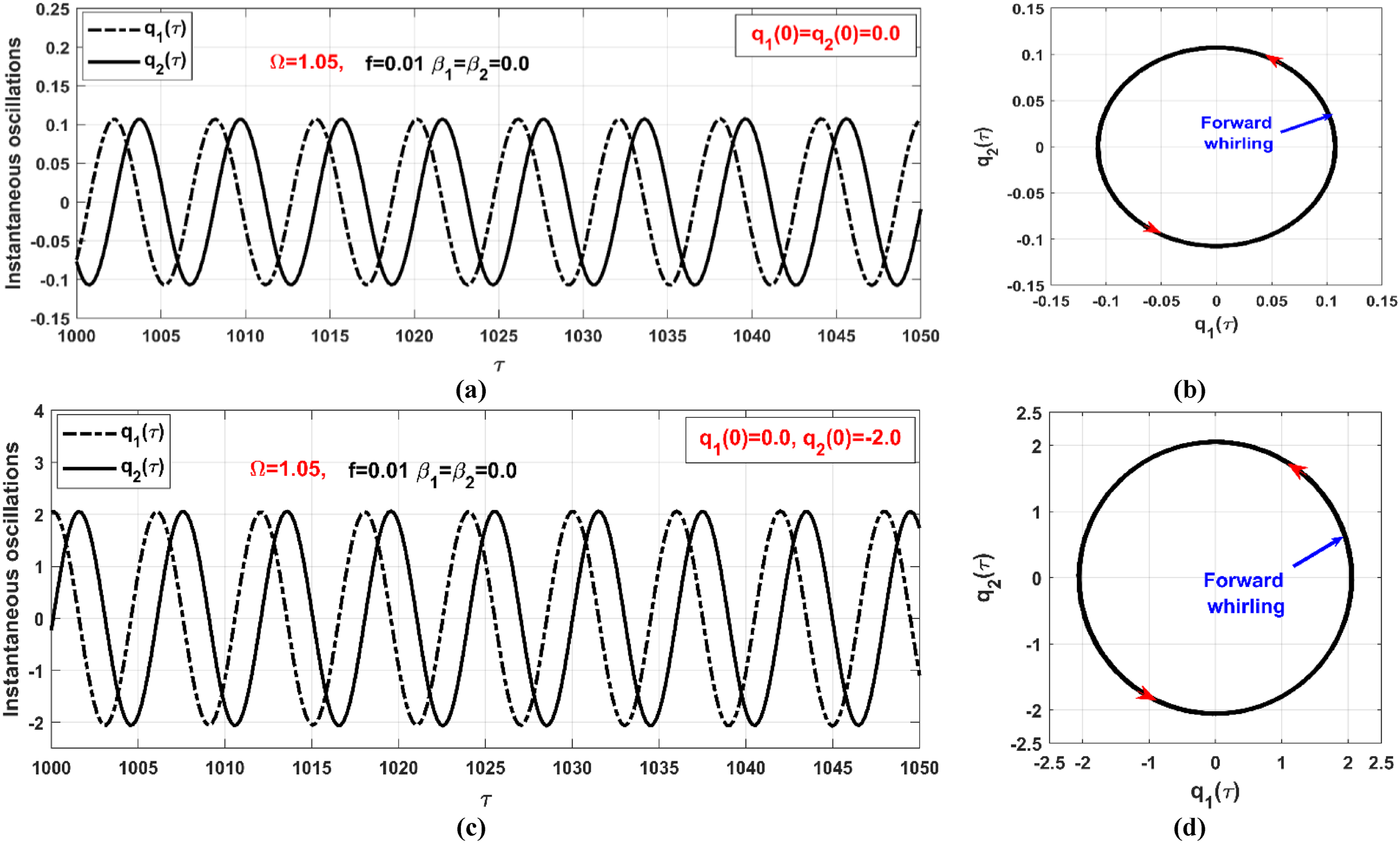
To discern the initial conditions that drive the rotor to oscillate according to either Solution I or Solution II, as depicted in Figure 5 for specific angular velocities range, we’ve mapped the basins of attraction in the space. These are illustrated in Figure 6, derived by numerically integrating equations (13.1) and (13.2) with parameters and assuming . Specifically, Figure 6(a) reveals the basins of attraction for Solutions I and II at , whereas Figure 6(b) showcases these basins at . Furthermore, the instantaneous lateral vibrations, coupled with their corresponding whirling orbits at steady-state conditions, are visualized in Figure 7 at , where bistable solutions are noted as per Figure 5. For instance, simulating the rotor’s motion at with initial conditions as shown in Figure 6(a), the system is anticipated to align with solution I, as evidenced in Figure 7(a) and (b). Conversely, by modifying the initial conditions to and , the rotor will oscillate following solution II, as portrayed in Figure 7(c) and (d). Hence, one can infer that even if the rotor system, when subjected solely to external excitation, exhibits a bistable solution, it invariably demonstrates a circular forward whirling motion, as highlighted in the orbit plots of Figure 7(b) and (d).
Basins of attraction of the system according to Figure 5 (i.e., ) at the initial velocities : (a) at , and (b) at .
Sensitivity of the rotor vibrations to the initial conditions according to Figures 5 and 6 at : (a, b) instantaneous motion and whirling orbit at , (c, d) instantaneous motion and whirling orbit at .
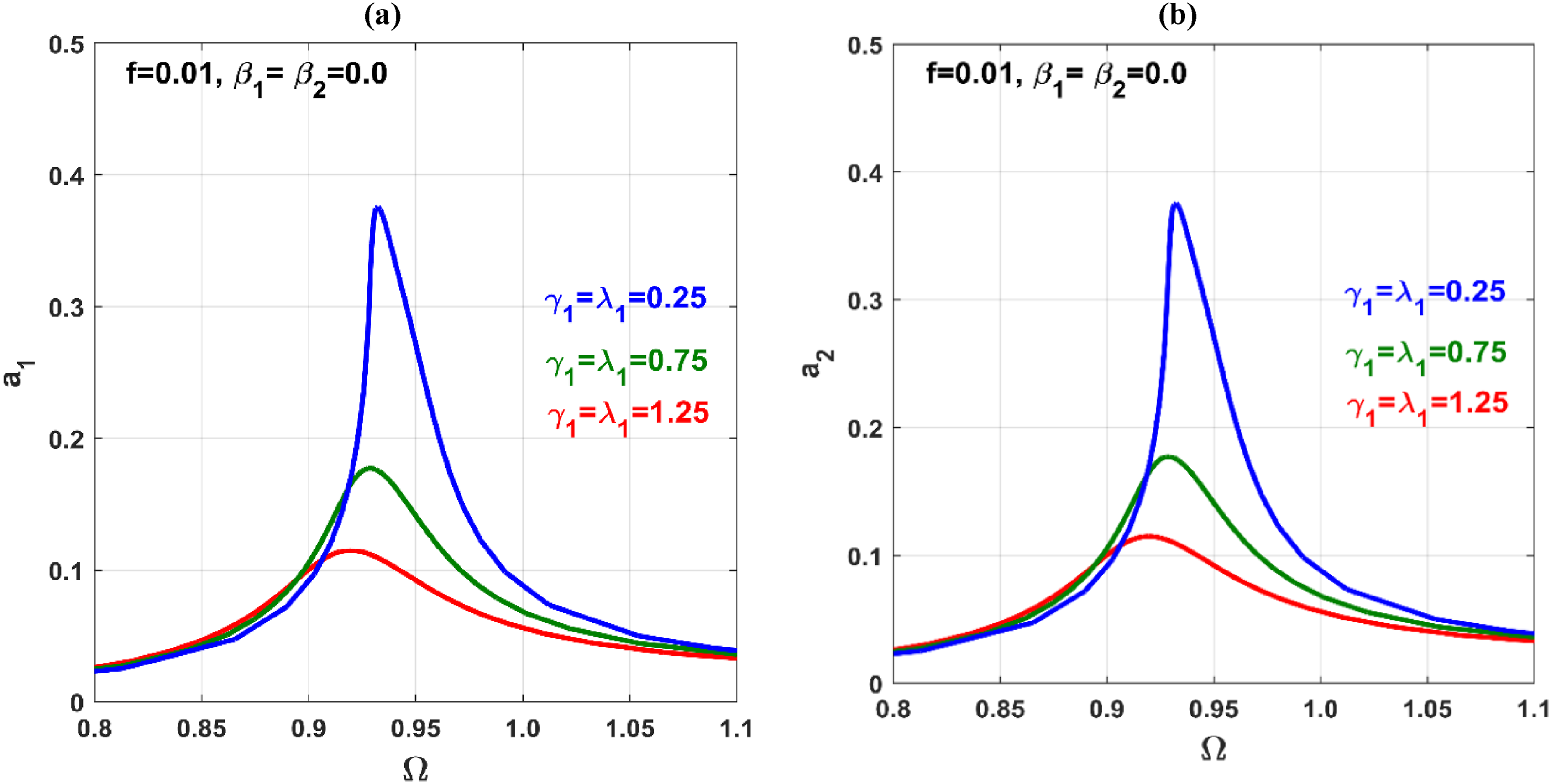
Regarding the proposed control strategy, and are designated as the control gains of , while and signify the feedback gains. The influence of and on the externally excited rotor model (specifically when and ) is illustrated in Figures 8 and 9. This is achieved by solving equations (23.1) to (23.4). Figure 8 portrays a consistent decrease in the oscillation amplitudes and as the gain increase from to . The figure further highlights the elimination of the nonlinear bifurcation associated with solution multiplicity. Here, the system consistently exhibits a monostable solution for each rotational speed , contrasting the pronounced bifurcation in the uncontrolled rotor observed in Figures 5 to 7.
Vibration amplitudes and of the rotor system versus the angular velocity when at three different levels of the linear control gains and .
Vibration amplitudes and of the rotor system versus the angular velocity when at , and the corresponding time responses and at and .
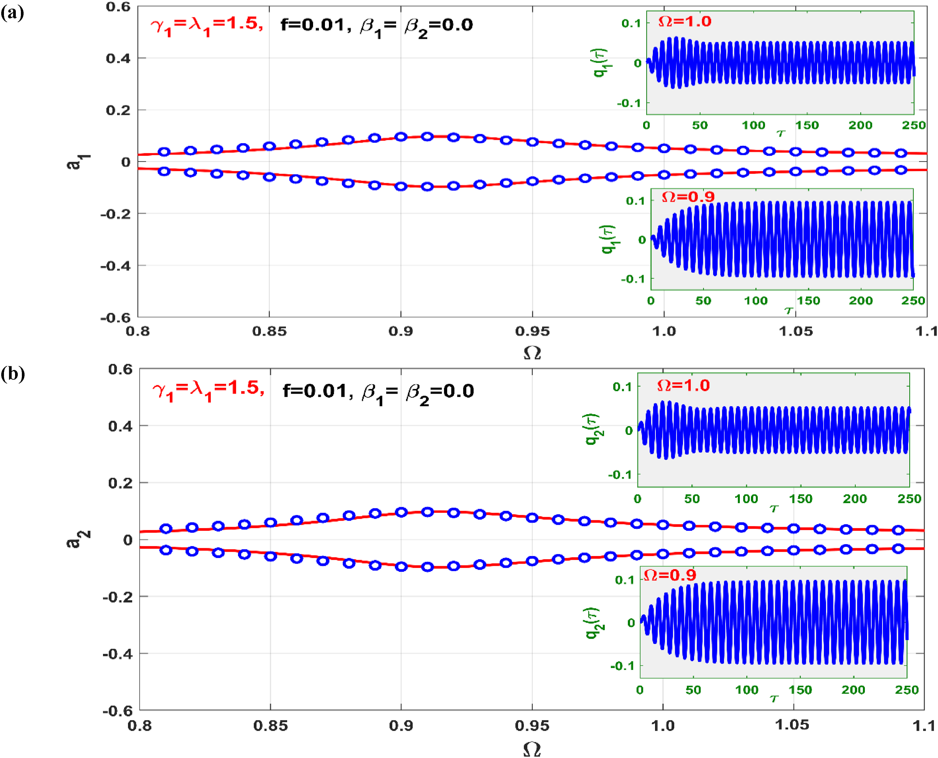
Figure 9 essentially replicates the content of Figure 8, but at . However, it includes both the upper and lower envelopes, which define the steady-state vibration amplitudes of the rotor’s periodic solutions, as expressed in equations (22.1) and (22.2) (i.e., and ). Furthermore, Figure 9 also presents the full time response (transient and steady-state) of the system model at and . This is achieved by integrating equations (13.1) and (13.2) using ODE15s over the time range . A close examination of Figure 9 reveals a remarkable alignment between the bifurcation diagram, which dictates steady vibration amplitudes, and the numerically obtained system time response.
Parametric excitation
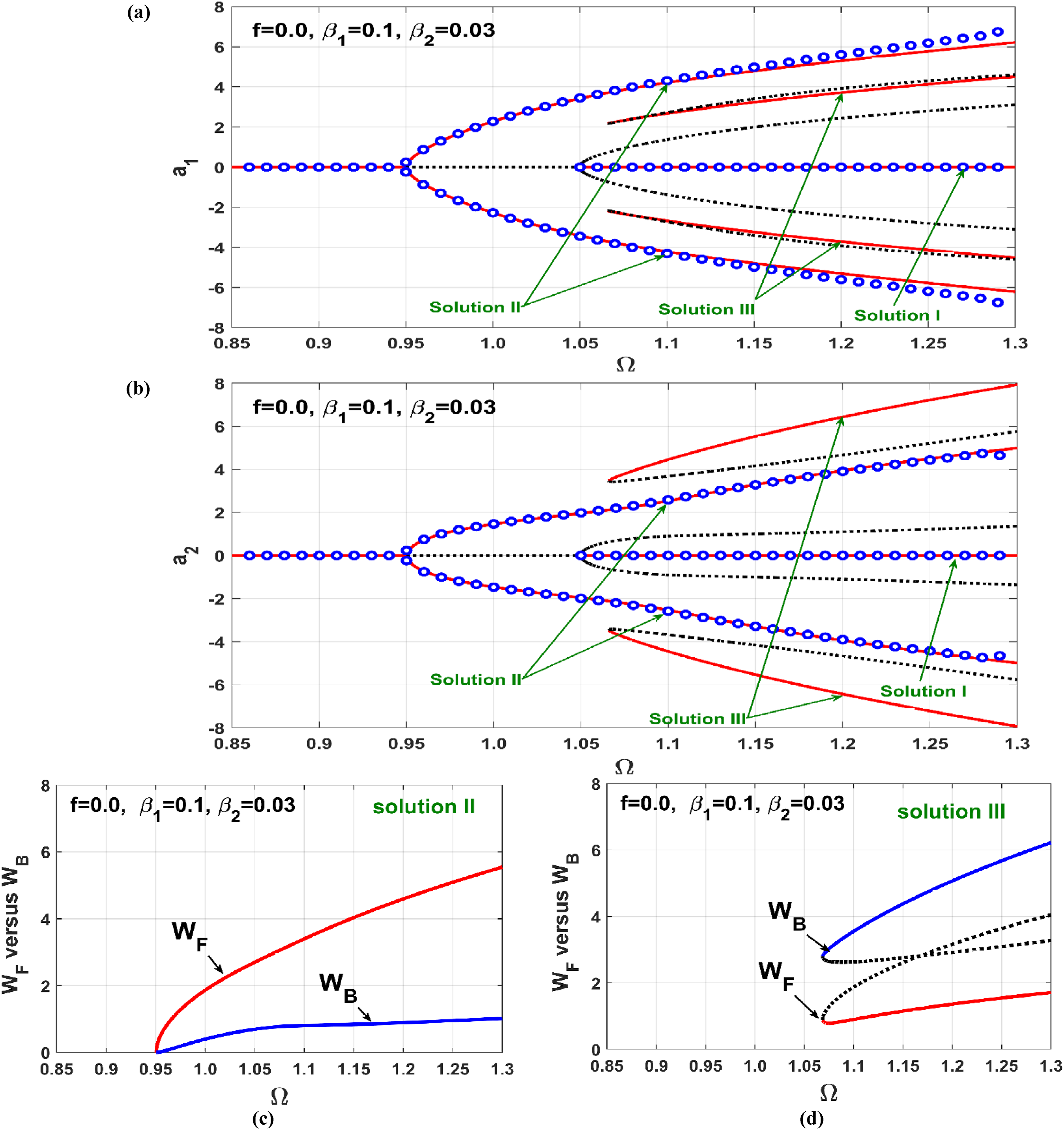
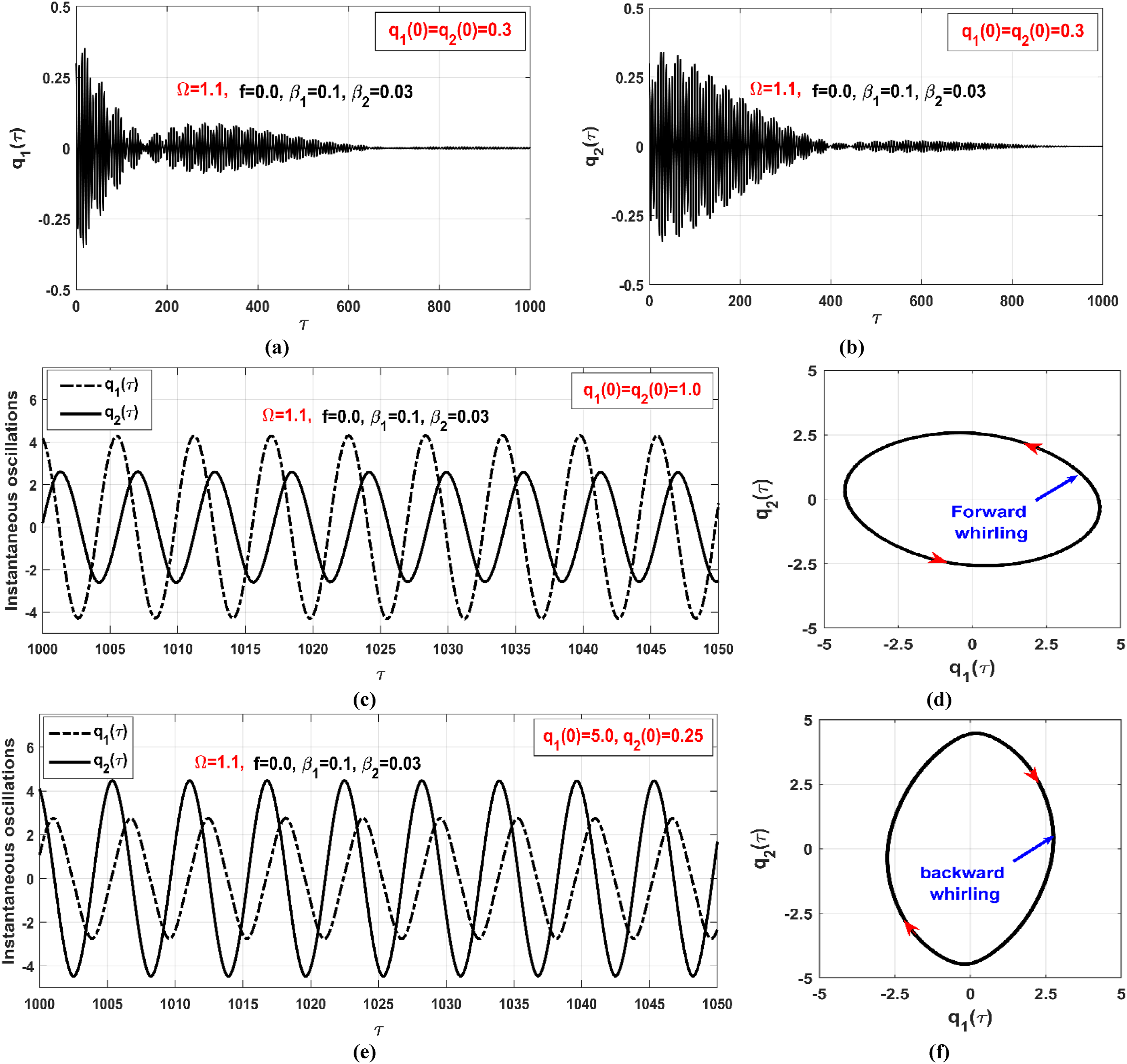
This section discusses the nonlinear dynamics of the system when subjected to pure multi-parametric excitations at zero-disc eccentricities. Figure 10(a) and (b) illustrate the amplitude bifurcation of the uncontrolled rotor when and within the range of . From the figure, it is evident that the system exhibits stable trivial solutions () regardless of the system’s initial conditions (i.e., ) as long as . However, when the rotor operates with an angular velocity within the range of , the system will oscillate in one of two modes based on the initial conditions. The first mode is an unstable trivial lateral motion () that occurs only with zero initial conditions. The second mode is a nontrivial periodic motion that occurs with nonzero initial conditions. Furthermore, the figure illustrates that as soon as exceeds , the rotor exhibits three stable periodic solutions. One of these solutions is a stable trivial solution, referred to as Solution I, while the other two are nontrivial periodic solutions referred to as Solution II and Solution III.
(a, b) Uncontrolled vibration amplitudes and versus the angular velocity when and , (c) forward whirling on Solution II branch because , (d) backward whirling on Solution III branch because .
From Figure 10(a) and (b), it’s evident that both Solution I and Solution II have been numerically validated, as indicated by the hollow blue circles, using the same numerical algorithm that was employed for Figure 5(a) and (b), as described above. In contrast, Solution III remains an elusive solution, one that has yet to be validated. Capturing this solution necessitates the use of very specific initial conditions. Furthermore, to illustrate the whirling direction corresponding to the nontrivial solutions, and are plotted for Solution II and Solution III, as shown in Figure 10(c) and (d), respectively. It is clear that the rotor whirls forward when following the Solution II branch and vibrates backward when following the Solution III branch.
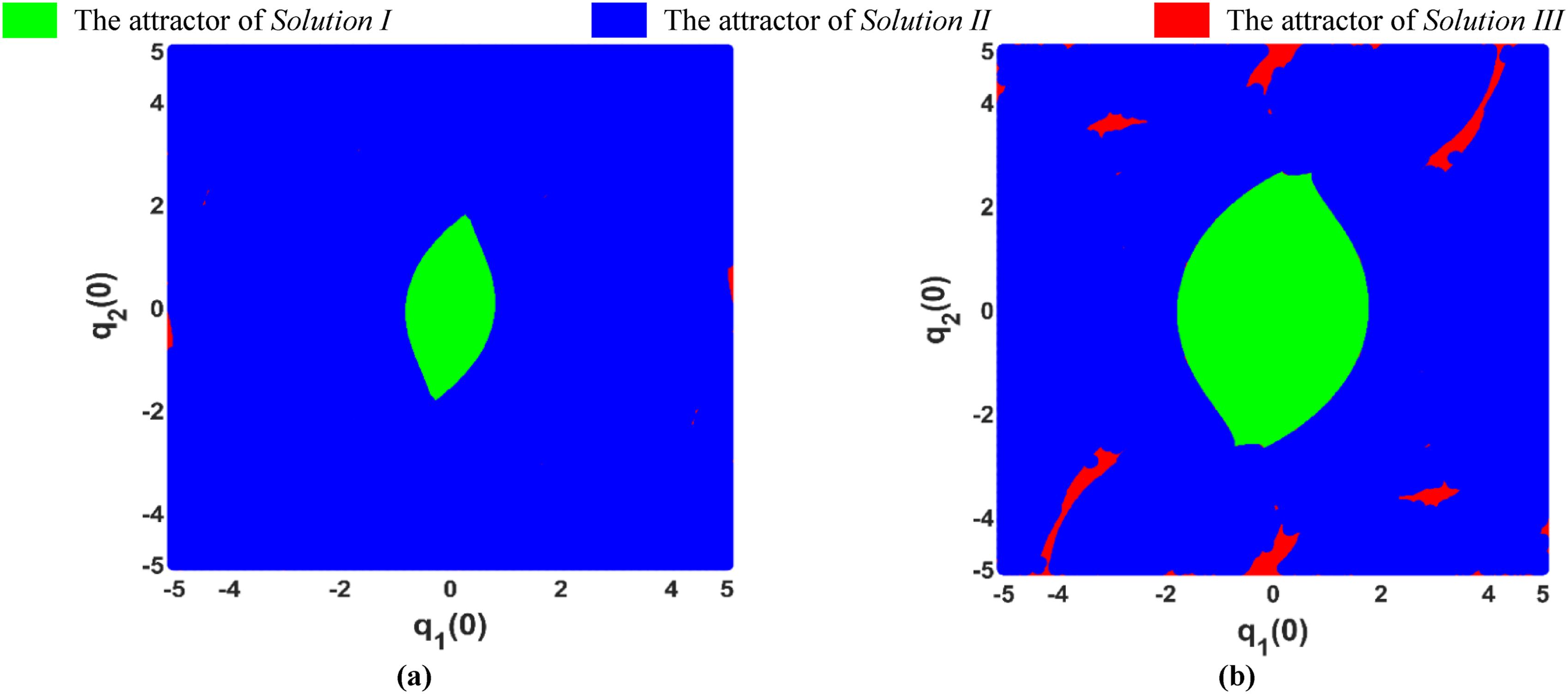
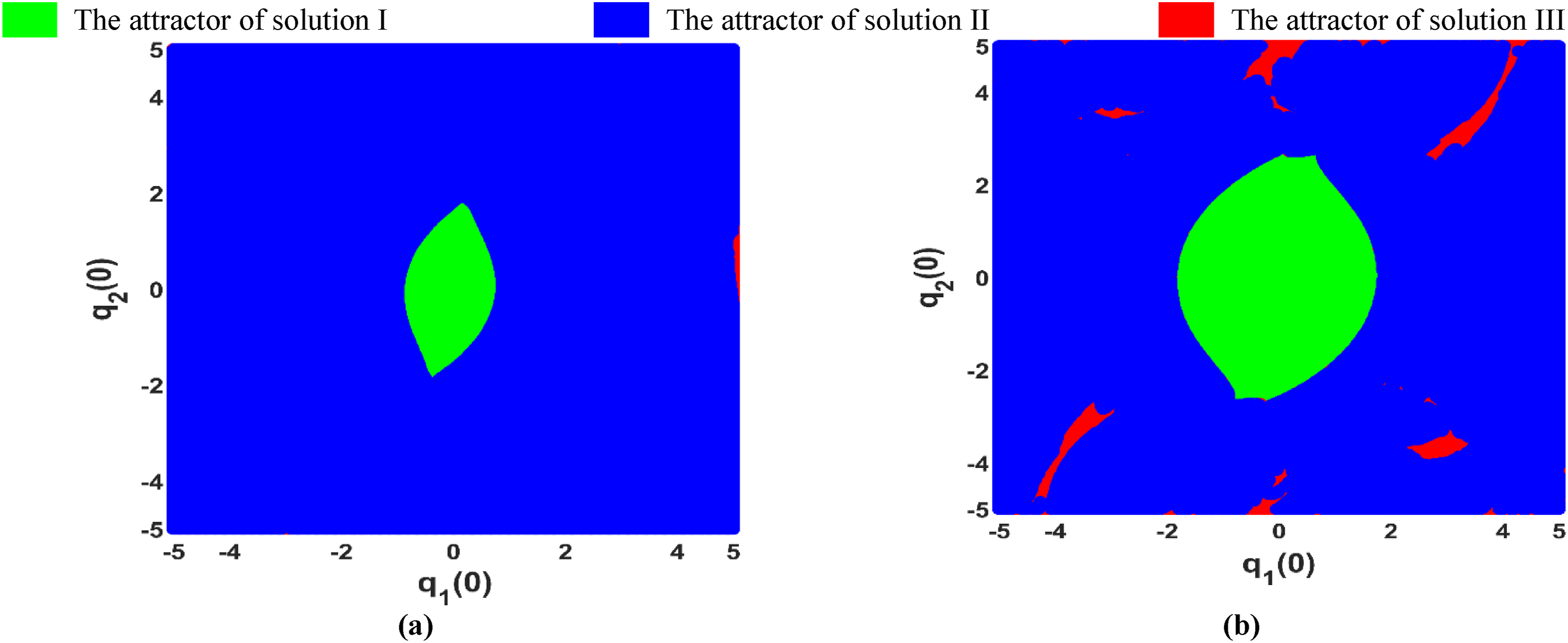
Consequently, basins of attraction for these solutions have been mapped out in the space, as depicted in Figure 11(a) and (b), in accordance with Figure 10 when and assuming . In these figures, the basins for Solution I, Solution II, and Solution III are represented by the colors green, blue, and red, respectively. The basin of attraction for Solution I is represented as a connected region centered at the origin , while the remaining area signifies the basin of attraction for Solution II, except for small irregular and scattered regions that form the basins of attraction for Solution III.
Basins of attraction of the system according to Figure 10 (i.e., ) at the initial velocities : (a) at , and (b) at .
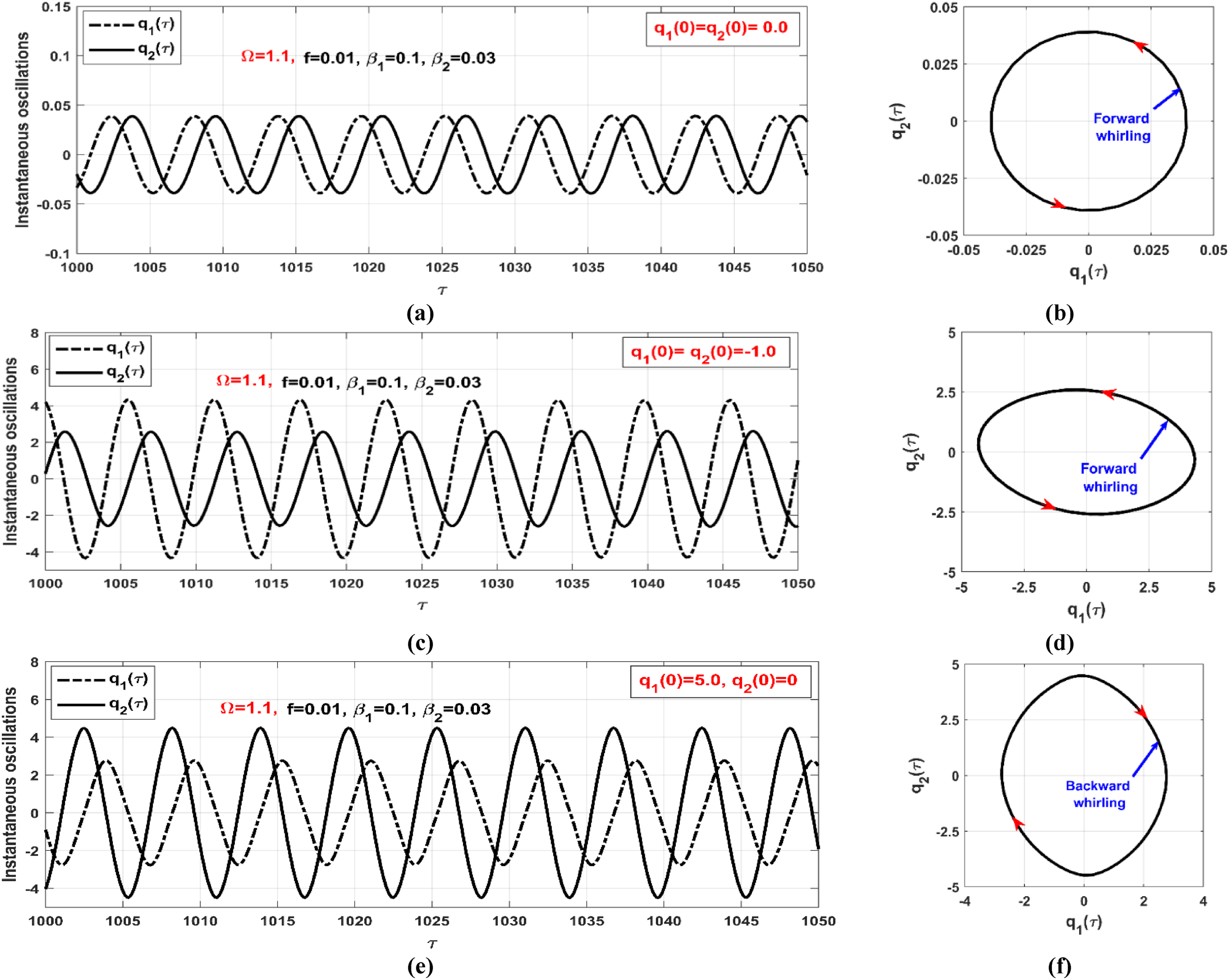
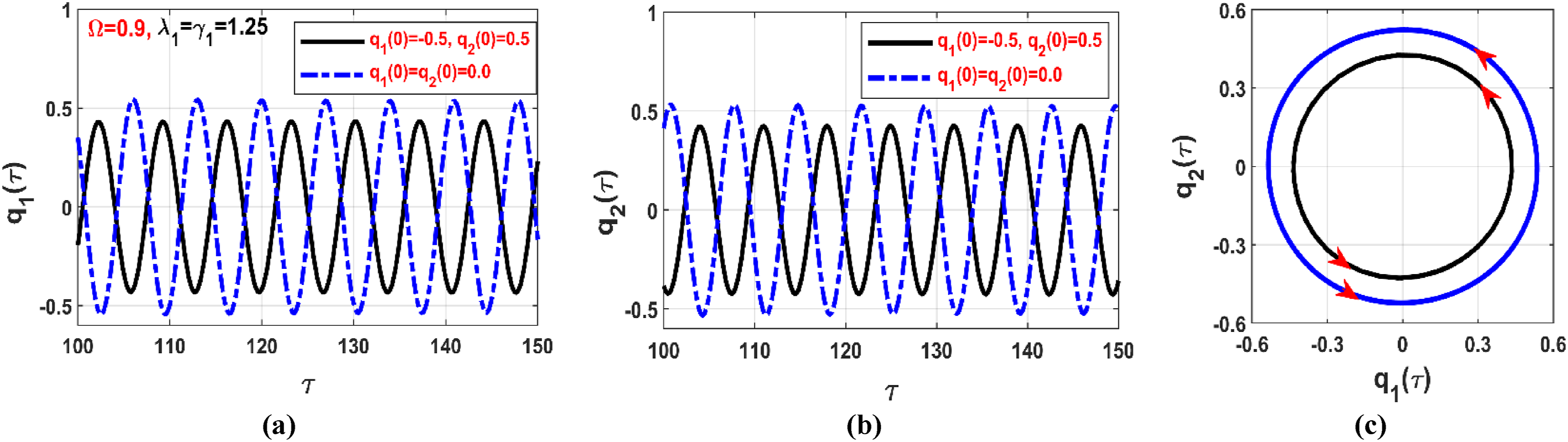
The rotor system’s three oscillation modes (namely, Solutions I, II, and III) under multi-parametric excitation are numerically illustrated in Figure 12. These simulations are based on three initial conditions corresponding to the green, blue, and red regions highlighted in Figure 11(a), where Figure 12(a) and (b) present the steady-state trivial oscillation (Solution I) of the parametrically excited rotor with initial positions is , corresponding to the green region of Figure 11(a). In addition, Figure 12(c) and (d) display the forward whirling motion (Solution II) of the system when the initial conditions are adjusted to , aligning with the blue region in Figure 11(a). Lastly, Figure 12(e) and (f) depict the backward whirling motion (Solution III) when the initial conditions are set to and , which corresponds to the red region in Figure 11(a).
Sensitivity of the rotor vibrations to the initial conditions according to Figures 10 and 11 at : (a, b) instantaneous motion at , (c, d) instantaneous motion and whirling orbit at , and (e, f) instantaneous motion and whirling orbit at .
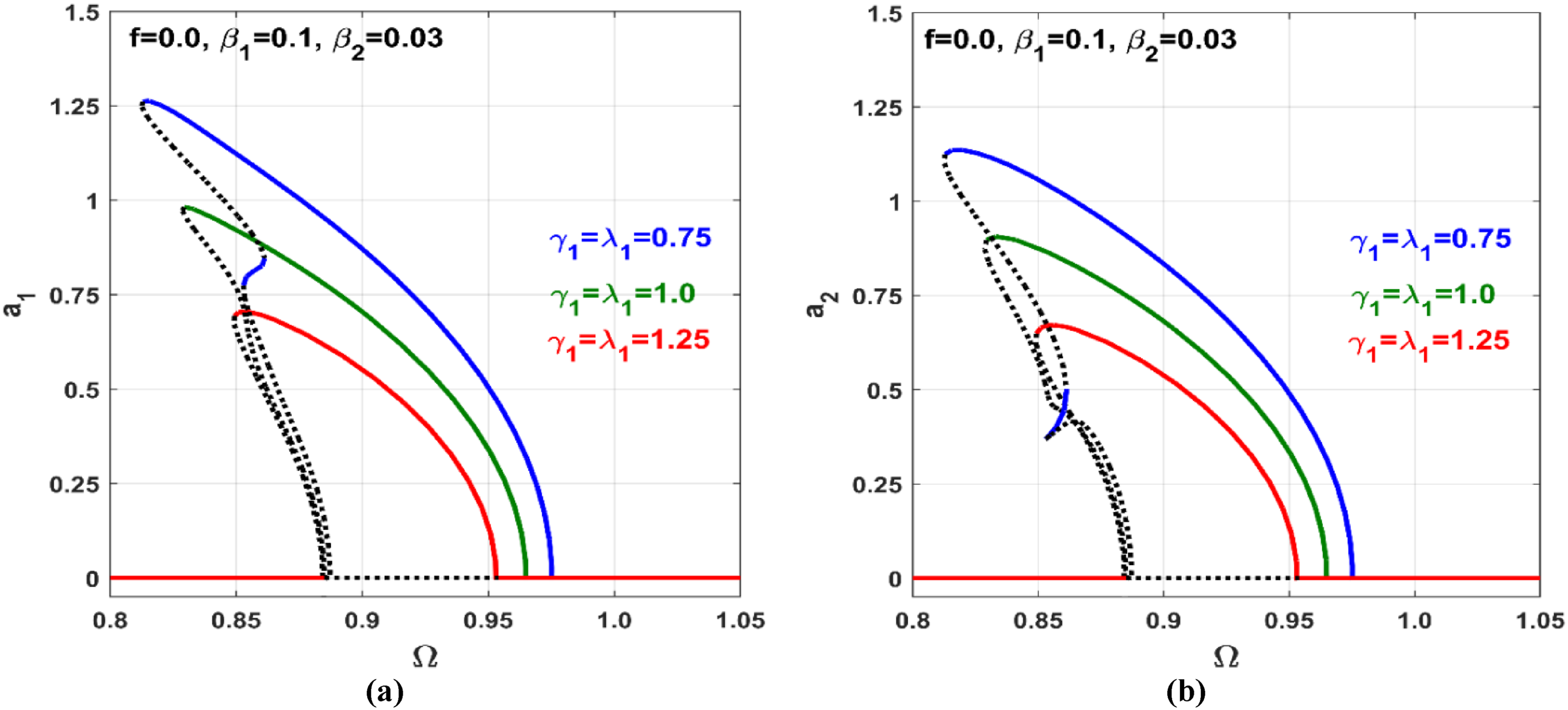
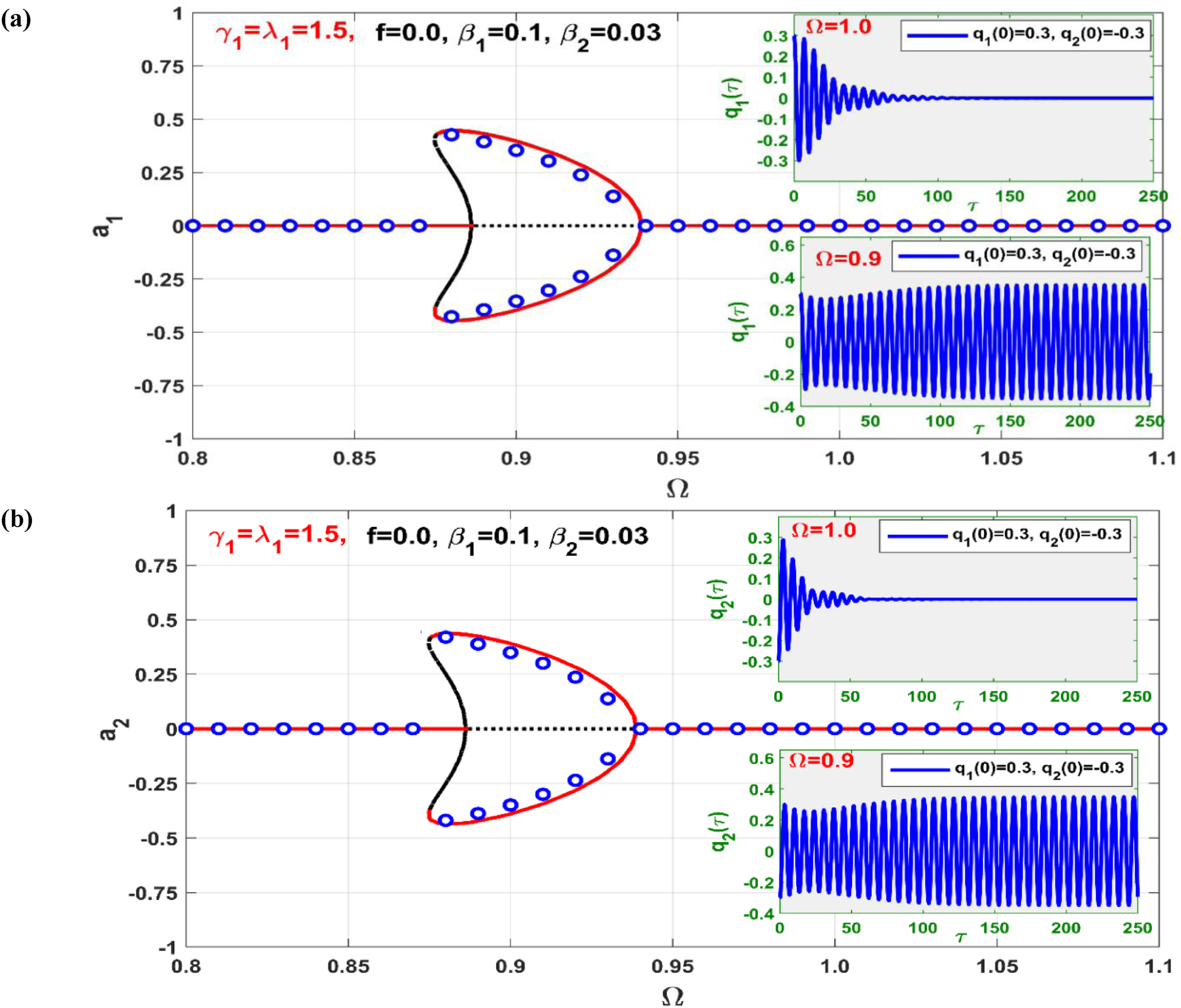
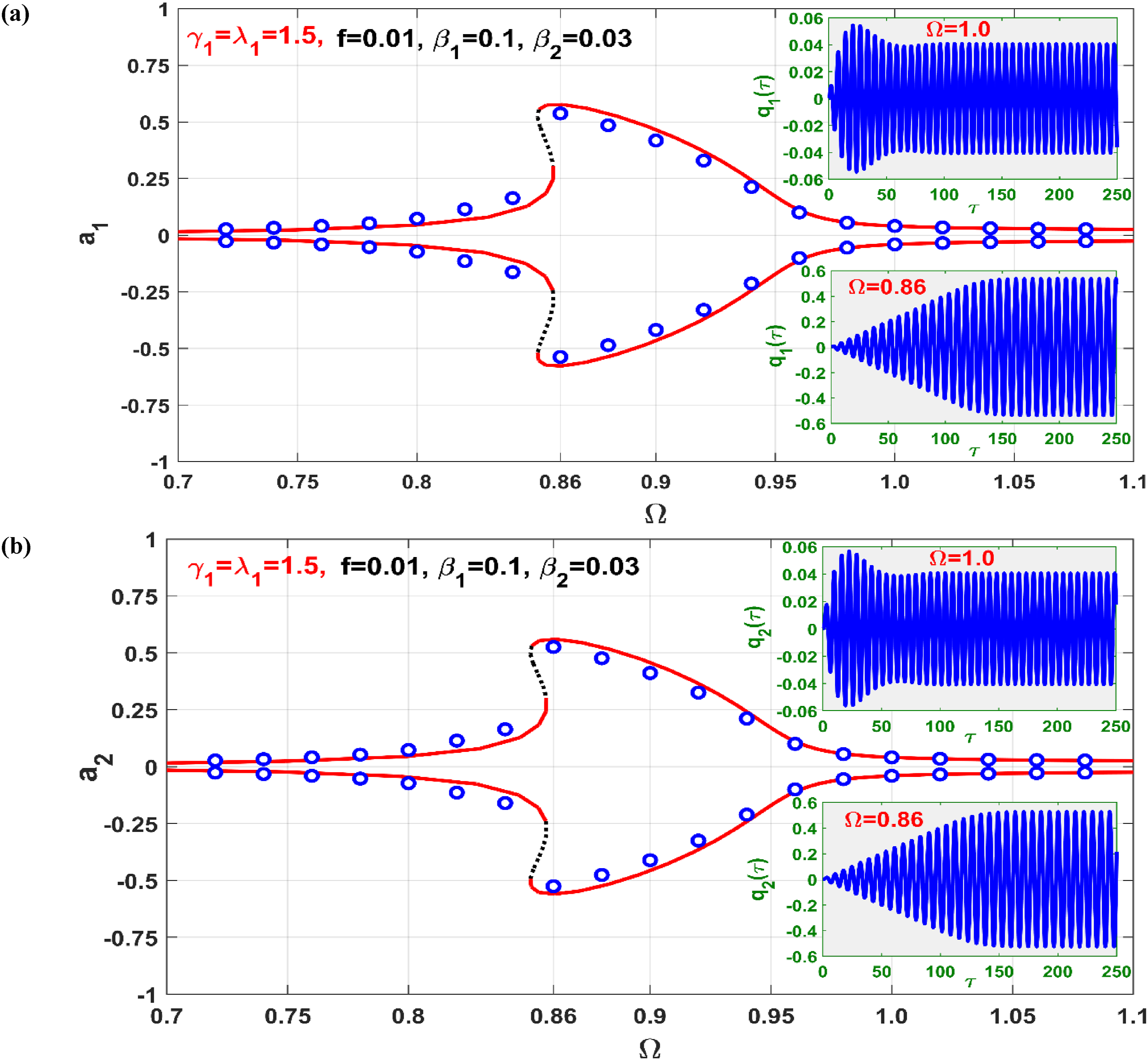
The efficiency of the in mitigating the catastrophic bifurcation of the system under multi-parametric excitation, as observed in Figures 10 through 12, is detailed in Figures 13 and 14. Figure 13 depicts the lateral amplitudes of the rotor controlled under multi-parametric excitation with control gains set to values of and . When juxtaposed with Figure 10, which represents the uncontrolled system, it’s evident that integrating the into the rotor modifies the system frequency response curve’s orientation from bending right (indicating hard spring characteristics) to left (suggesting soft spring characteristics). Such a transformation might result from the magnetic coupling between the rotor and controller via a four-pole electromagnetic actuator. This figure also substantiates the eradication of the intricate bifurcation traits of the uncontrolled rotor seen in Figures 10 through 12. Notably, the rotor’s parametric oscillations steadily decline as the gain increases. Figure 14 sheds light on the rotor’s parametric oscillation motion bifurcation as the gain ascends to . Here, blue hollow circles serve as the numerical verification, derived from solving using the ODE15s solver, as previously mentioned. Additionally, the figure showcases the comprehensive time response of the system model for and . Detailed scrutiny of Figure 14 highlights an impressive congruence between the bifurcation diagram defining steady vibration amplitudes and the numerically derived system time response.
Vibration amplitudes and of the system versus the angular velocity when and at three different levels of the control parameters and .
Vibration amplitudes and of the system versus the angular velocity when and at , and the corresponding time responses and at and .
Mixed excitations
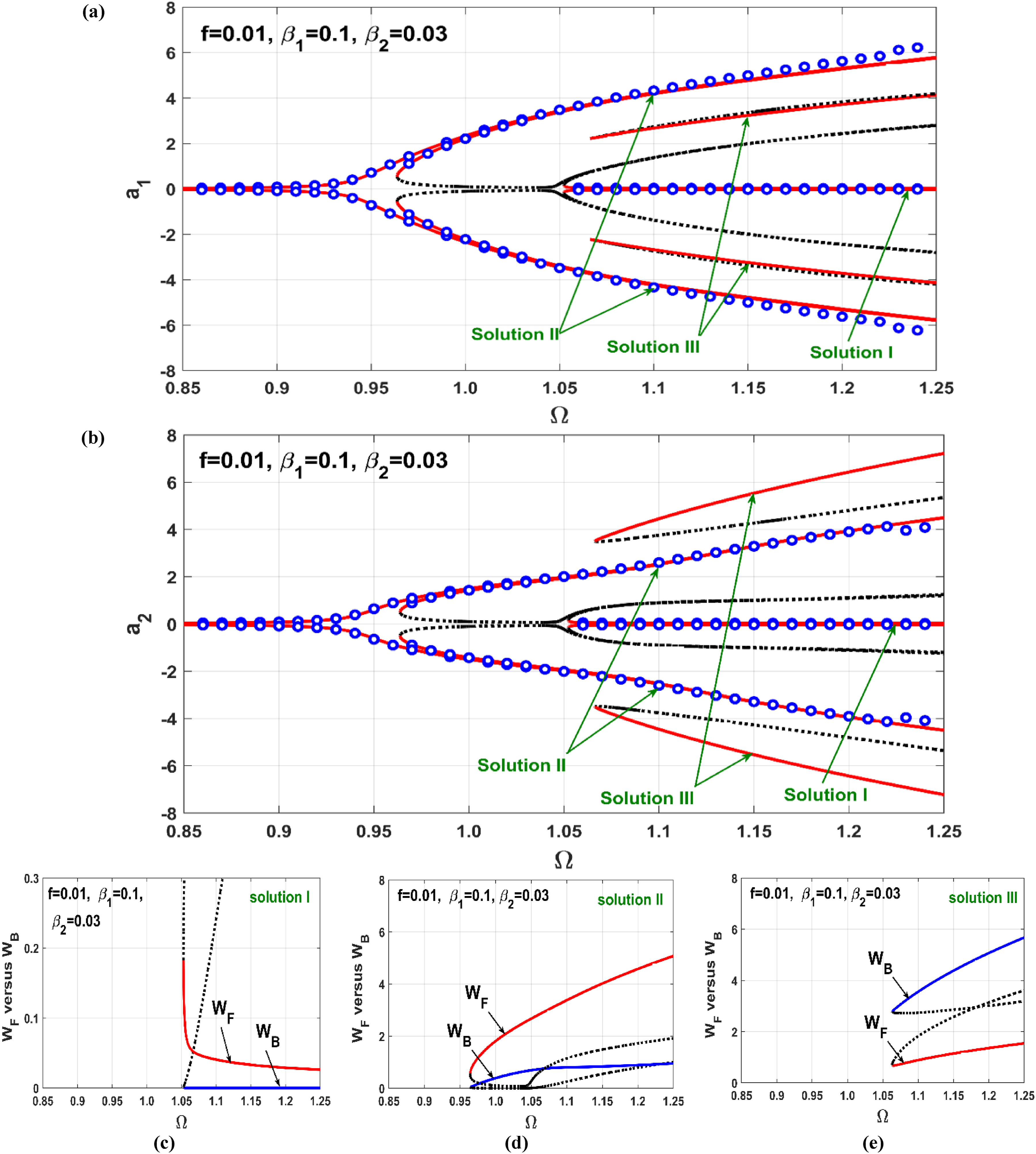
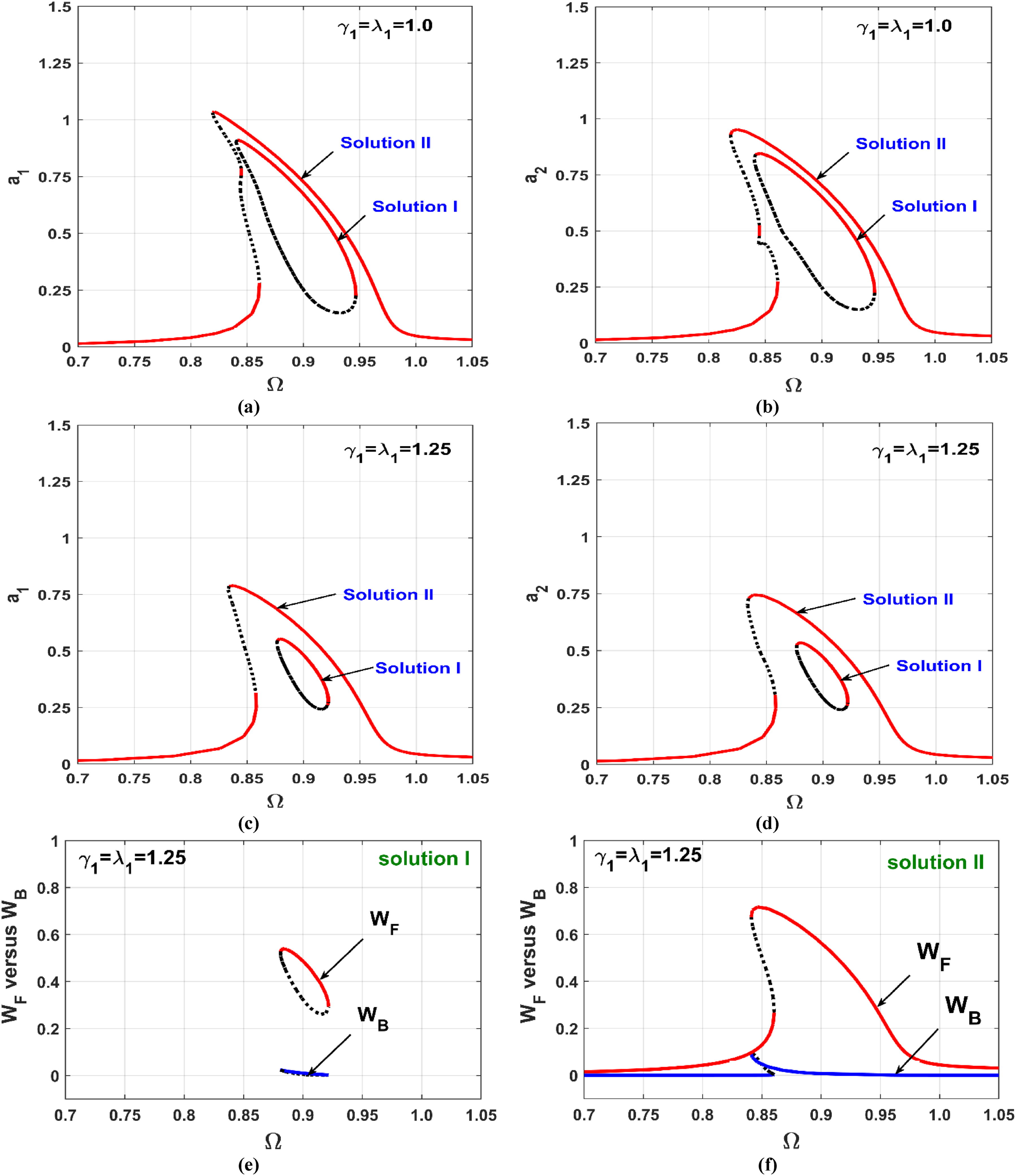
The bifurcation characteristics of the asymmetric rotor under simultaneous external and multi-parametric excitations (i.e., mixed excitations) are explored in this section, both before and after active control. Figure 15 illustrates the bifurcation of the uncontrolled system’s lateral oscillation against angular velocity at and . Figure 15(a) and (b) reveal that the rotor system under mixed excitation may exhibit monostable, bistable, or tristable solutions depending on the rotational speed. Furthermore, Figure 15(c) to (e) depict that the system exhibits forward whirling when following Solution I and Solution II branches, while it oscillates in a backward direction when following Solution III branches.
(a, b) Uncontrolled vibration amplitudes and versus the angular velocity when and , (c) forward whirling on Solution I branch because , (d) forward whirling on Solution II branch because , (e) backward whirling on Solution III branch because .
Furthermore, the figure demonstrates that Solutions I and II have been numerically validated using ODE15s, as explained earlier, with the numerical solution represented by hollow blue circles. However, Solution III necessitates specific initial conditions to be stimulated. Consequently, the basins of attraction in the space for the solutions of equations (13.1) and (13.2) (i.e., Solutions I, II, and III) are obtained when and , as shown in at and . The basins for Solution I, Solution II, and Solution III are represented by the green, blue, and red colors, respectively. The basin of attraction for Solution I is obtained as a connected region centered at the origin, while the remaining area signifies the basin of attraction for Solution II, except for small irregular and scattered regions forming the basin of attraction for Solution III. Based on the bifurcation diagram in Figure 15 and corresponding to the basins of attraction in Figure 16, three different initial conditions have been selected within the three basins illustrated in Figure 16(a) to simulate the instantaneous oscillations of the system, as shown in Figure 17. The figure confirms that the system may oscillate with one of three nontrivial periodic solutions, either with forward or backward whirling, depending on the initial condition.
Basins of attraction of the system according to Figure 15 (i.e., and ) at the initial velocities : (a) at , and (b) at .
Sensitivity of the uncontrolled rotor to the initial conditions according to Figures 15 and 16 at : (a, b) instantaneous motion at , (c, d) instantaneous motion and whirling orbit at , and (e, f) instantaneous motion and whirling orbit at and .
The bifurcation diagram of lateral vibration for the controlled rotor, subjected to simultaneous external and multi-parametric excitations, is presented in Figure 18 at various values of the control gains ( and ). A comparison between Figure 18 and the bifurcation diagram of the uncontrolled rotor in Figure 15 reveals a noteworthy transformation: the original hardening spring characteristic of the rotor before control has been replaced by a softening characteristic. This alteration ultimately results in the manifestation of nonlinear resonance below the rotor critical speed (). Furthermore, Figure 18 indicates that oscillation amplitudes exhibit a monotonic decreasing trend as a function of the gains . Despite the applied control techniques, it is observed that the elimination of nonlinear behaviors in the rotor system is challenging at lower control gains ( or ). In this regime, the system continues to exhibit bistable solutions within a specific range of rotor angular speed.
(a, b, c, d) Vibration amplitudes and of the system versus the angular velocity when and at different levels of the gains and : (a, b) , (c, d) , and (e, f) forward whirling on Solution I and II branches when because .
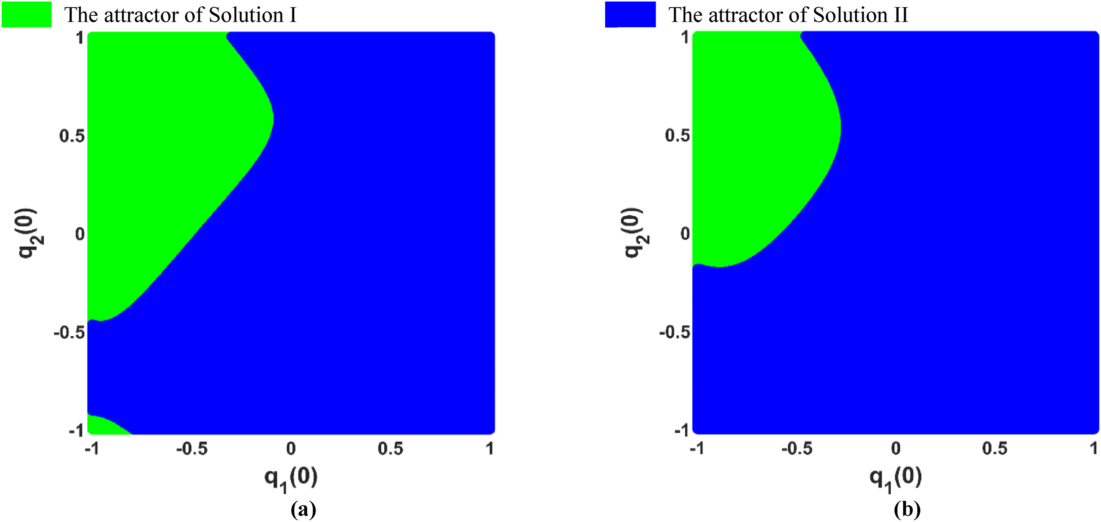
To validate the accuracy of the presented results in Figure 18, the basins of attraction for both solutions I and II at are established, as depicted in Figure 19. In Figure 19(a), the basins of attraction for solutions I and II at according to Figure 18(a) and (b), while Figure 19(b) displays the basins of attraction at as per Figure 18(c) and (d). The basin of attraction for solution I is highlighted in green, while the basin of attraction for solution II is represented in blue.
Basins of attraction of the system at and according to Figure 18 (i.e., ): (a) , and (b) .
Subsequently, the time response of the controlled rotor is simulated based on the basins of attraction shown in Figure 19(b), as illustrated in Figure 20. This simulation involves solving equations (13.1) to (13.4) with and . Two distinct initial conditions are considered: the first, with and , falls within the solution I attractor, while the second, with , falls within the solution II attractor. Figure 20 demonstrates the coexistence of two periodic solutions of the controlled system, with either solution being stimulated depending on the initial conditions. Additionally, Figure 20(c) highlights that both periodic solutions (i.e., solutions I and II) correspond to forward whirling oscillations that agree Figure 18(e) and (f), where . However, by increasing the control gains, the system can be compelled to respond akin to a linear system even in the case of mixed excitation, as depicted in Figure 21. This figure illustrates the elimination of bistability irrespective of angular velocity when is increased to , in contrast to the intricate bifurcation behaviors reported in Figures 15, 16, 17, 18, 19 and 20.
Sensitivity of the control rotor to the initial conditions according to Figure 19(b) at : (a, b) instantaneous oscillation at steady-state, and (c) whirling orbits.
Vibration amplitudes and of the system versus the angular velocity when and at .
Control failure and rub-impact effects
Based on the provided normalized equations of motion (equations (13.1) to (13.4)), the normalized instantaneous oscillations, denoted as and , are defined as and , respectively. Here, and represent the actual displacements of the rotor in the and directions, while signifies the nominal clearance between the rotor and stator, as illustrated in Figure 2. Additionally, and are expressed as periodic functions as given in equations (22.1) and (22.2), where and . If the steady-state lateral vibrations or/and of the rotor exceed unity, it implies that the actual instantaneous oscillations and/or will surpass the clearance , potentially leading to rubbing and/or impact between the rotor and stator. Within this section, we delve into the dynamics of the controlled rotor and the effect of rub-impact when either the controller connected to the or directions experience abrupt failure. The primary aim of this discussion is to explore rotor dynamics and assess system stability in the event of a controller failure.
Control failure at direction
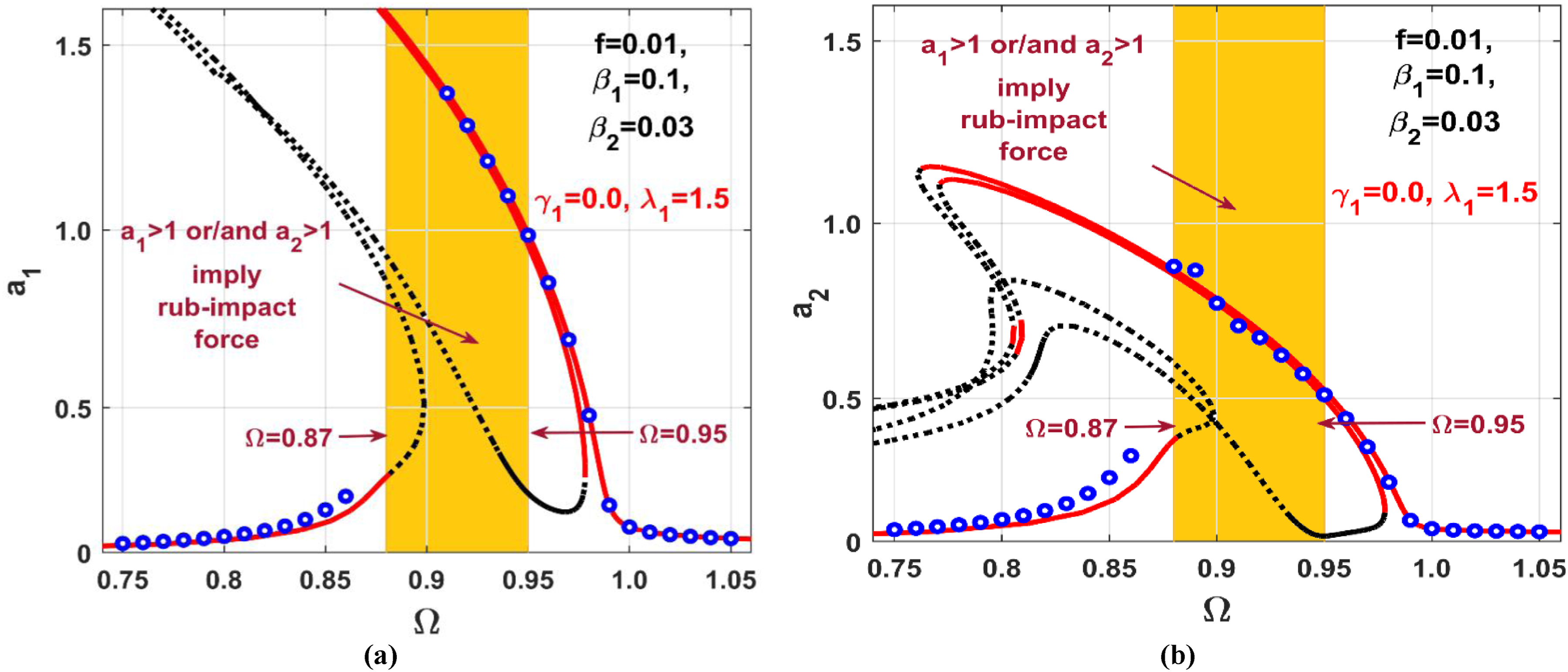
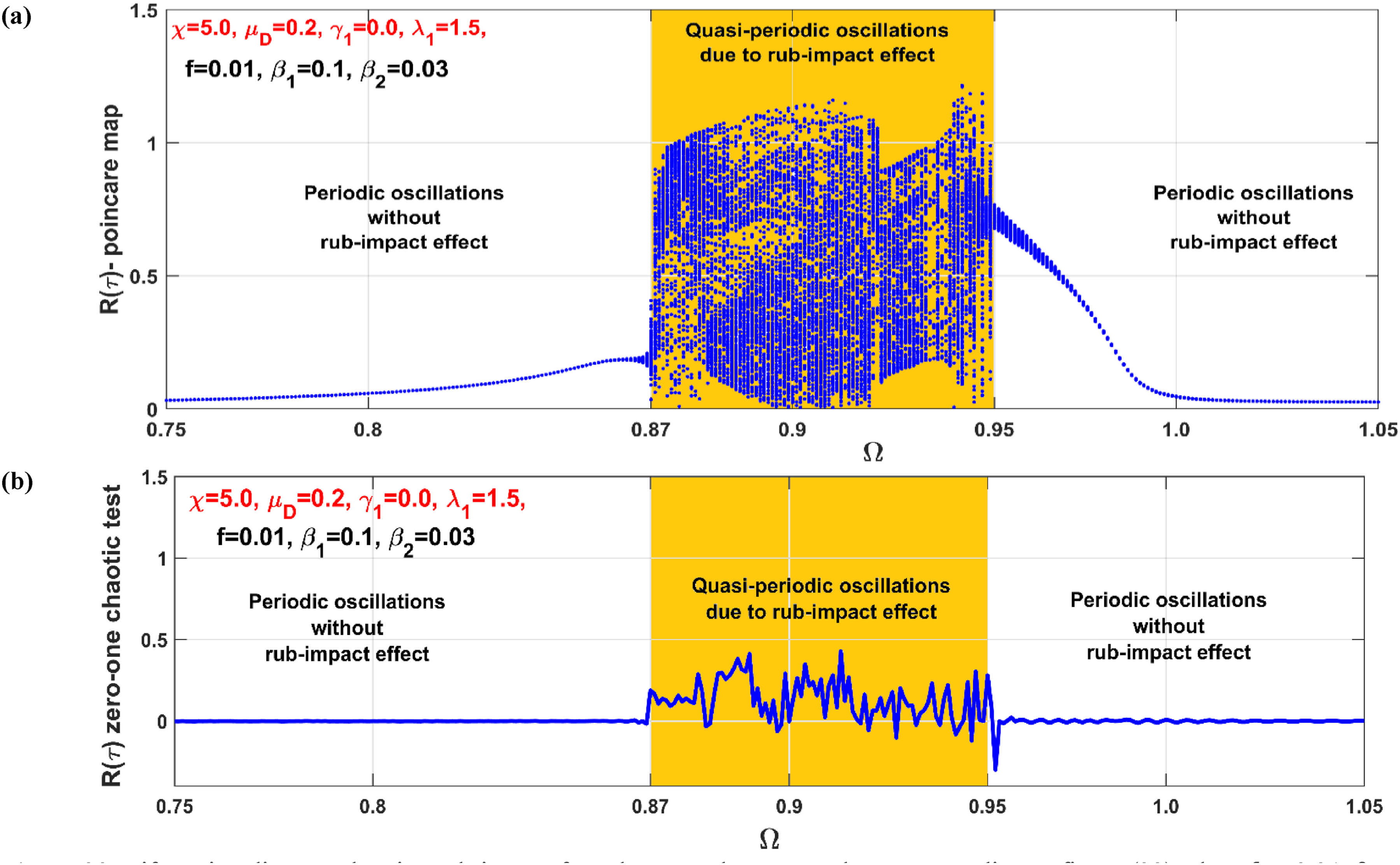
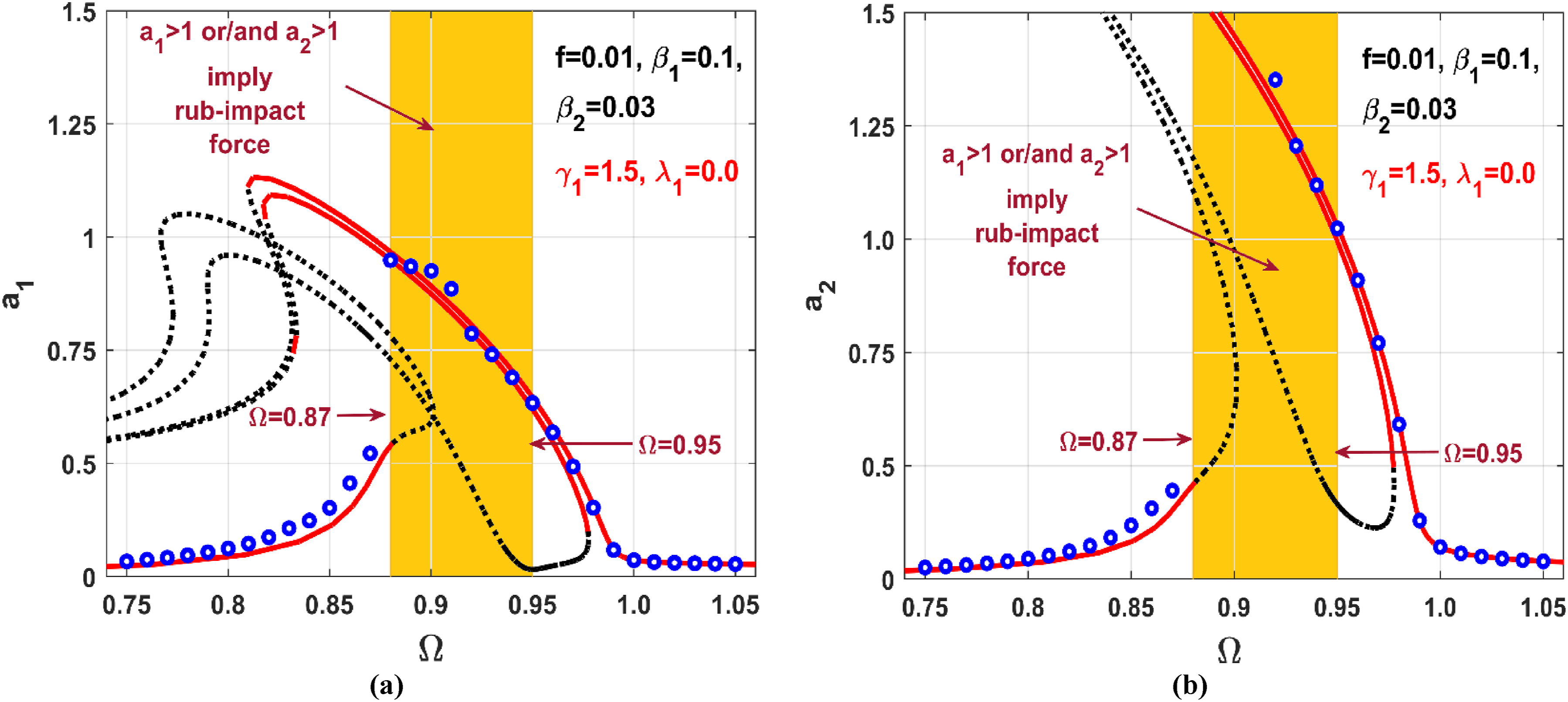
The simulation of the failure of the controller linked to the direction is achieved by setting the control gain (refer to equation (7)). Subsequently, the rotor’s vibration amplitudes ( and ) are plotted against angular velocity, solving equations (23.1) to (23.4) with and , as depicted in Figure 22. This figure illustrates asymmetric response curves in both and directions due to the asymmetric control gains. Particularly, Figure 22(a) indicates that lateral oscillations in the direction exceeding unity may occur within the angular velocity range of . This signifies that the failure of the direction controller may result in rub and/or impact force between the rotor and stator, provided the angular velocity falls within the specified range. Drawing upon the results from Figure 22, the entire discontinuous system model (equations (13.1) to (13.4)), encompassing the rub-impact effect ( and ), is numerically solved. The corresponding bifurcation diagram is established and presented in Figure 23(a). This figure is generated by plotting the Poincaré map for the steady-state radial oscillation of the rotor () against its angular speed , serving as a bifurcation parameter on the interval , using an incremental step-size .
Vibration amplitudes and of the system versus the angular velocity at and 2 = 0.03 when and .
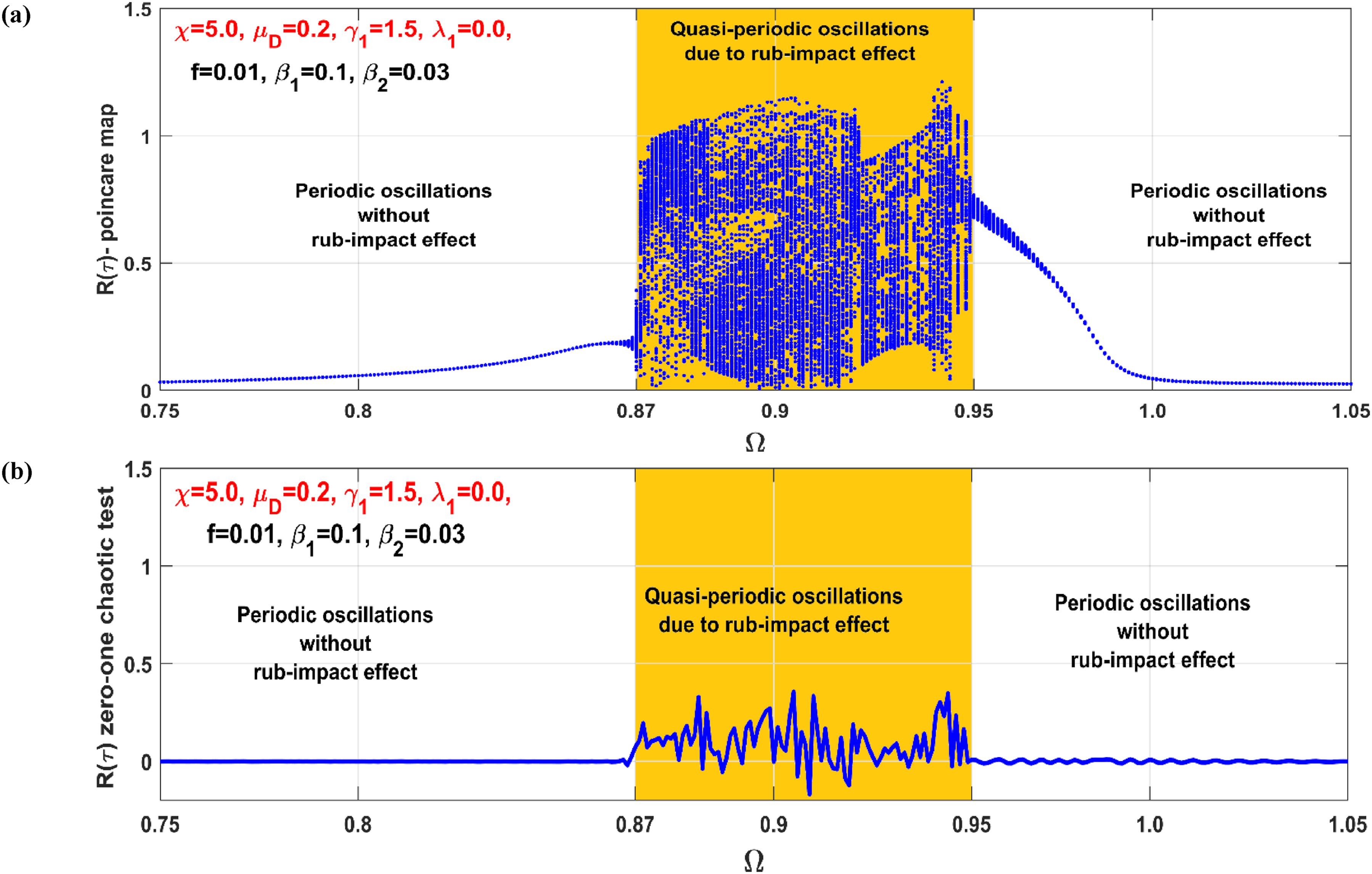
Bifurcation diagram showing rub-impact force between the rotor and stator according to Figure 22 when at , and .
Figure 23(a) elucidates that the rotor system can exhibit periodic motion outside the range . Conversely, within this interval, the system manifests nonperiodic oscillation due to the rub-impact occurrence, as deduced from Figure 22. To delve into the nature of these nonperiodic motions reported in Figure 23(a), the zero-one chaotic test (refer to Refs. 46,47) has been employed to explore chaotic behaviors in the instantaneous radial oscillations across the interval . The output of the 0-1 algorithm remains below within the interval , indicating that the system exhibits quasiperiodic oscillations when rub-impact occurs between the rotor and actuator.
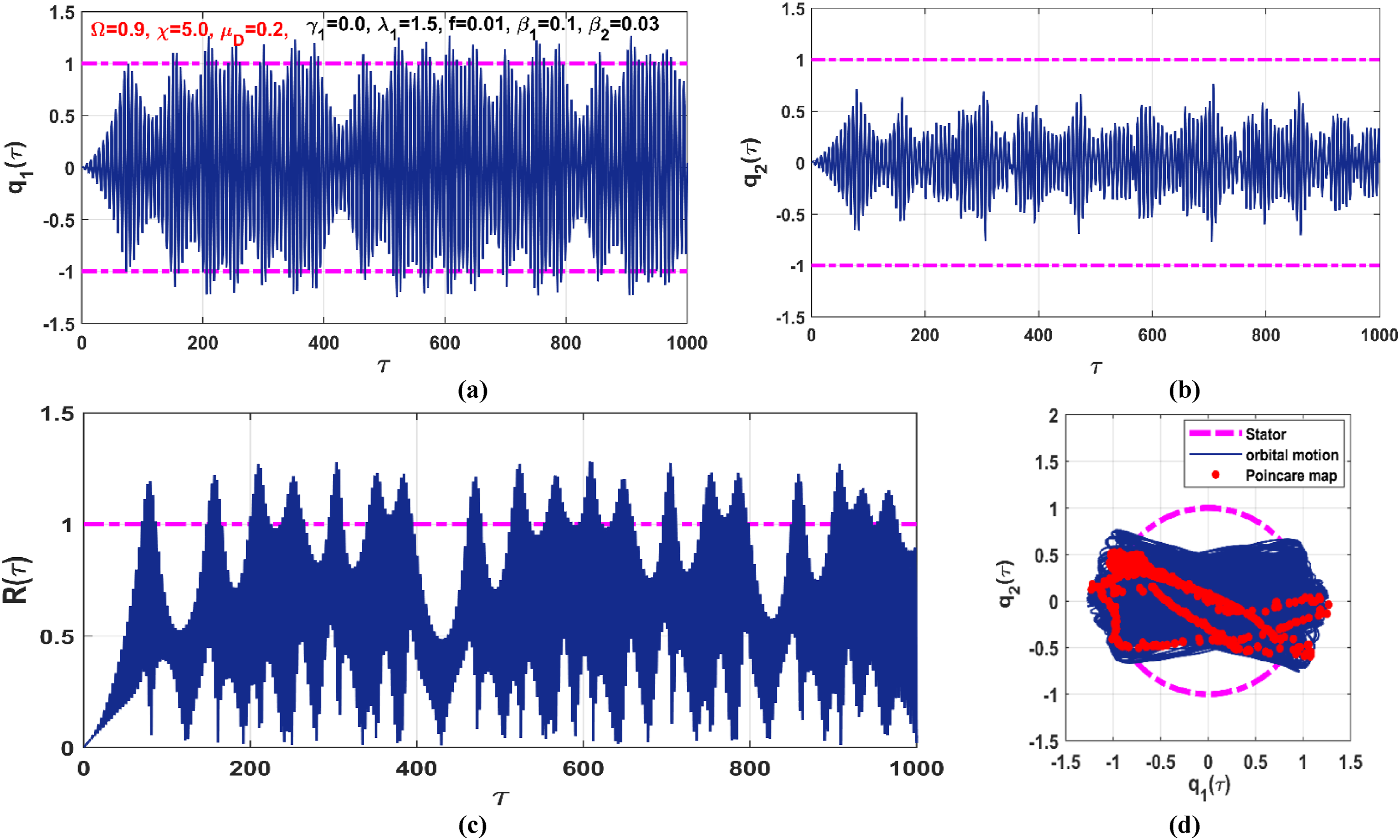
Based on Figures 22 and 23 at , the instantaneous oscillation of the controlled system when the controller connected to the direction is failed (i.e., when and ) has been shown in Figure 24. The figure is obtained by solving equations (13.1) to (13.4) numerically when and along the time interval with zero initial conditions. Figure 24(a) and (b) illustrate the lateral vibrations ( and ) in both and directions, while Figure 24(c) and (d) show the instantaneous radial vibrations and the corresponding orbital motion of the rotor, where the dashed magenta line denotes the stator circumference. It is clear that the rotor subjected to lateral rub-impact effect in direction only when and as clearly shown in Figures 24(a), which induces quasiperiodic oscillations as depicted from the Poincaré map shown in Figure 24(d).
The rotor time response according to Figure 23 (i.e., at and ) at : (a, b) the instantaneous lateral quasiperiodic oscillations in and directions, (c) the quasiperiodic radial oscillations, and (d) the orbital motion and the corresponding Poincaré map.
Control failure at direction
In contrast to the previous section, the current section examines the nonlinear dynamics and stability behaviors of the controlled rotor in the event of a failure in the controller connected to the direction. This is simulated by setting and . Figure 25 displays the steady-state lateral vibrations of the rotor against when and . The figure reveals that the system may experience rub-impact forces when the rotor rotation speed is within the interval , as indicated by . This is a deviation from Figure 22, where it was observed that was the primary factor for rub-impact occurrence.
Vibration amplitudes and of the system versus the angular velocity at and 2 = 0.03 when and .
Following the methodology employed in the previous section, a bifurcation diagram and the corresponding zero-one chaotic test have been established, as depicted in Figure 26 based on the results from Figure 25. The outcomes demonstrate that the system will exhibit quasiperiodic motion within the range ; otherwise, it will display periodic motion. Finally, a numerical simulation of the entire discontinuous model, as given by equations (13.1) to (13.4) with and , is illustrated in Figure 27, clearly showcasing the quasiperiodic oscillation.
Bifurcation diagram showing rub-impact force between the rotor and stator according to Figure (25) when at and .
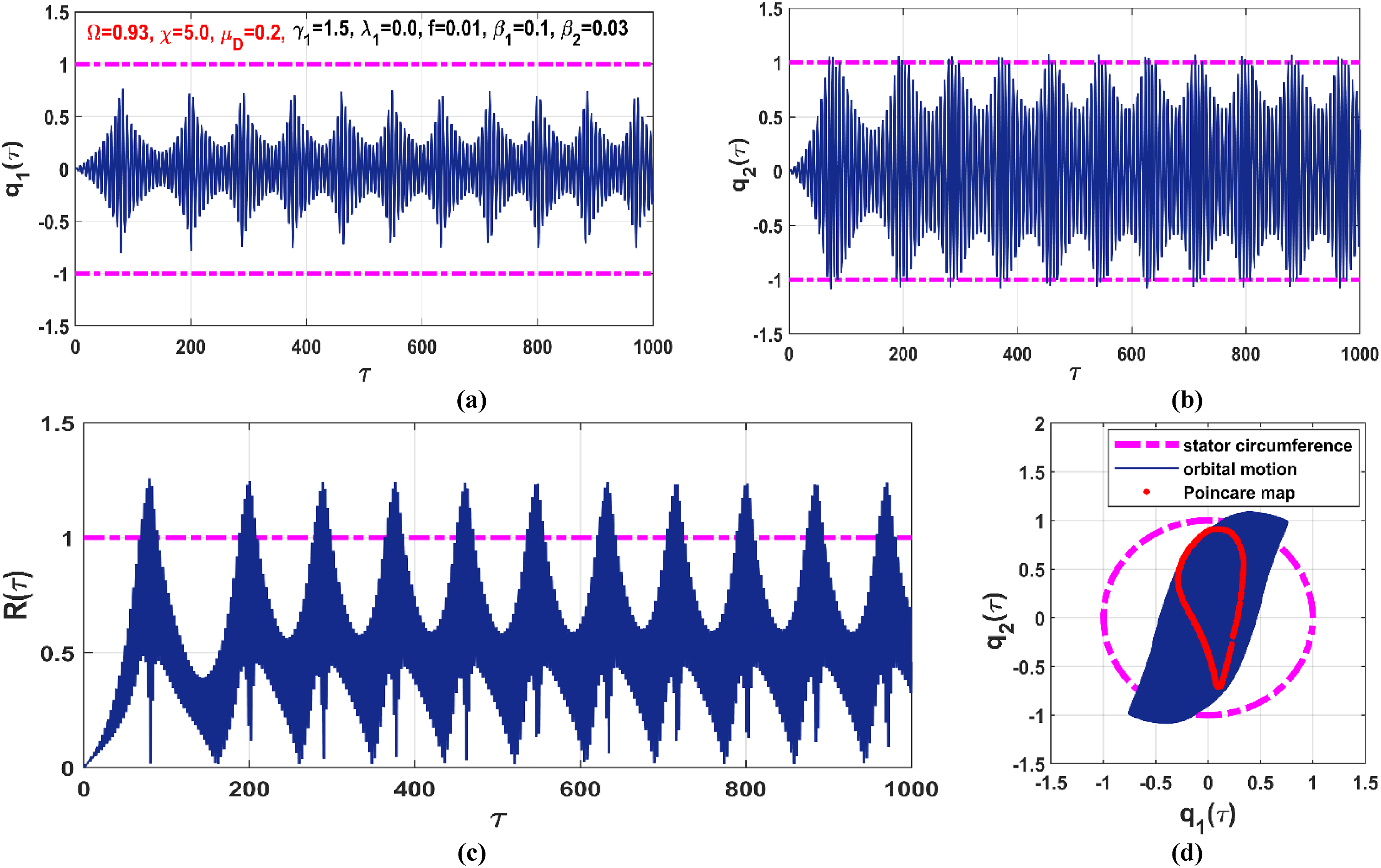
The rotor time response according to Figure 26 (i.e., at and ) at : (a, b) the instantaneous lateral quasiperiodic oscillations in and directions, (c) the quasiperiodic radial oscillations, and (d) the orbital motion and the corresponding Poincaré map.
Remarks
The motion bifurcation and vibration control of a DOF system simulating the lateral oscillation of a nonlinear rotor model having asymmetric restoring forces have been discussed within this article. The has been employed as an active damper, utilizing four magnetic poles as active actuators for applying manipulated control signals. The mathematical model of the entire system, grounded in classical mechanics principles and electromagnetic theory, is established as a DOF nonlinear system subject to external and multi-parametric excitations. These are coupled to two DOF systems simulating the dynamics of the , with the inclusion of the rub-impact effect between the actuator circumference and the rotor, resulting in a complex discontinuous dynamical system. Applying the multiple time scales solution procedure, the established mathematical model has been solved, and corresponding slow-flow modulating equations are extracted. The article then evaluates the performance of the in controlling undesired nonlinear dynamics under external, multi-parametric, and mixed excitations based on the obtained slow-flow equation s. Additionally, the stability of the system is explored in the event of the failure of one of the connected controllers in the horizontal or vertical directions, as a precautionary procedure. Finally, the following points can be remarked based on the introduced analysis and discussions:
(1) Despite the complexity of the considered dynamical system, all obtained analytical results align well with numerical simulations.
(2) However, the rotating disc eccentricity being responsible for rotor external excitation, the main source of multi-parametric excitation is the asymmetry in restoring forces of the rotating shaft.
(3) In the cases of external excitation only, the nonlinear rotor system may oscillate with nonzero monostable or bistable forward whirling motion, depending on the system’s angular velocity.
(4) In the case of multi-parametric excitation only, the considered rotor model can respond with one of three oscillation modes: trivial oscillation, forward whirling, or backward whirling, depending on both the angular velocity and initial states.
(5) In the case of mixed excitation, the system responds with one of three motions depending on both the angular velocity and initial states: two forward whirling motions and one backward whirling oscillation.
(6) Coupling the to the rotor model via a magnetic actuator with the proper setting of the control gains can suppress unwanted vibrations and eliminate catastrophic bifurcations, regardless of the excitation force either external, multi-parametric, or mixed case.
(7) The failure of one of the connected controllers either in the horizontal or vertical directions may cause a local rub-impact effect between the rotor and pole housing.
(8) The occurrence of the rub-impact effect does not force the rotor to exhibit unbounded motion but induces a quasiperiodic oscillation with partial rub-impact mode.
Supplemental Material
Supplemental Material - An asymmetric rotor model under external, parametric, and mixed excitations: Nonlinear bifurcation, active control, and rub-impact effect
Supplemental Material for An asymmetric rotor model under external, parametric, and mixed excitations: Nonlinear bifurcation, active control, and rub-impact effect by Randa A Elashmawey, Nasser A Saeed, Wedad A Elganini and Mohamed Sharaf in Journal of Low Frequency Noise, Vibration & Active Control
Data availability statement
The data used to support the findings of this study are included in this article.*
Footnotes
Acknowledgments
The authors present their appreciation to King Saud University for funding this research through Researchers Supporting Program number (RSPD2024R704), King Saud University, Riyadh, Saudi Arabia.
Author contributions
Conceptualization, R.E, N.S., W.E, and M.S.; methodology, R.E, N.S., W.E, and M.S.; software, N.S. and M.S.; validation R.E, N.S., W.E, and M. S.; formal analysis, N.S. and R.E.; investigation, R.E, N.S., W.E, and M.S.; writing-original draft preparation, N.S. and R.E; writing-review and editing, N.S., R.E, W.E, and M.S.; visualization, N.S., R.E, and M.S. All authors have read and agreed to the published version of the manuscript.
Declaration of conflicting interests
The author(s) declared no potential conflicts of interest with respect to the research, authorship, and/or publication of this article.
Funding
The author(s) disclosed receipt of the following financial support for the research, authorship, and/or publication of this article: This work was supported by the King Saud University for funding this research through Researchers Supporting Program number (RSPD2024R704), King Saud University, Riyadh, Saudi Arabia. Additionally, the authors are very grateful for the financial support from the National Key R&D Program of China (Grant No. 2023YFE0125900). Also, this work has been supported by the Polish National Science Centre, Poland under the grant OPUS 18 No. 2019/35/B/ST8/00980.
ORCID iD
Nasser A Saeed
Supplemental Material
Supplemental material for this article is available online.
References
1.
YamamotoT. On the vibrations of a shaft supported by bearings having radial clearances. Trans Jpn Soc Mech Eng1955; 21(103): 186–192. DOI: 10.1299/kikai1938.21.186.
2.
CveticaninL. Free vibration of a Jeffcott rotor with pure cubic non-linear elastic property of the shaft. Mech Mach Theor2005; 40: 1330–1344. DOI: 10.1016/j.mechmachtheory.2005.03.002.
3.
AdilettaGGuidoARRossiC. Non-periodic motions of a Jeffcott rotor with non-linear elastic restoring forces. Nonlinear Dynam1996; 11: 37–59. DOI: 10.1007/BF00045050.
4.
IshidaYInoueT. Internal resonance phenomena of the Jeffcott rotor with non-linear spring characteristics. Vib Acoust2004; 126(4): 476–484. DOI: 10.1115/1.1805000.
5.
YabunoHKashimuraTInoueT, et al.Non-linear normal modes and primary resonance of horizontally supported Jeffcott rotor. Nonlinear Dynam2011; 66(3): 377–387. DOI: 10.1007/s11071-011-0011-9.
6.
MalgolAVineeshKPSahaA. Investigation of vibration characteristics of a Jeffcott rotor system under the influence of nonlinear restoring force, hydrodynamic effect, and gyroscopic effect. J Braz Soc Mech Sci Eng2022; 44: 105. DOI: 10.1007/s40430-021-03277-x.
7.
ShahgholiMKhademSE. Primary and parametric resonances of asymmetrical rotating shafts with stretching nonlinearity. Mech Mach Theor2012; 51: 131–144. DOI: 10.1016/j.mechmachtheory.2011.12.012.
YiYQiuZHanQ. The effect of time-periodic base angular motions upon dynamic response of asymmetric rotor systems. Adv Mech Eng2018; 10(3): 1–12. DOI: 10.1177/1687814018767172.
11.
BaviRHajnayebASedighiHM, et al.Simultaneous resonance and stability analysis of unbalanced asymmetric thin-walled composite shafts. Int J Mech Sci2022; 217: 107047. DOI: 10.1016/j.ijmecsci.2021.107047.
12.
BaviRSedighiHMHajnayebA, et al.Parametric resonance and bifurcation analysis of thin-walled asymmetric gyroscopic composite shafts: an asymptotic study. Thin-Walled Struct2023; 184: 110508. DOI: 10.1016/j.tws.2022.110508.
13.
Chang-JianC-WChenC-K. Chaos of rub–impact rotor supported by bearings with non-linear suspension. Tribol Int2009; 42: 426–439. DOI: 10.1016/j.triboint.2008.08.002.
14.
WangJZhouJDongD, et al.Non-linear dynamic analysis of a rub-impact rotor supported by oil film bearings. Arch Appl Mech2013; 83: 413–430. DOI: 10.1007/s00419-012-0688-3.
15.
KhanloHMGhayourMZiaei-RadS. Chaotic vibration analysis of rotating, flexible, continuous shaft-disk system with a rub-impact between the disk and the stator. Commun Nonlinear Sci Numer Simulat2011; 16: 566–582. DOI: 10.1016/j.cnsns.2010.04.011.
16.
KhanloHMGhayourMZiaei-RadS. The effects of lateral–torsional coupling on the non-linear dynamic behavior of a rotating continuous flexible shaft–disk system with rub–impact. Commun Nonlinear Sci Numer Simulat2013; 18: 1524–1538. DOI: 10.1016/j.cnsns.2012.10.004.
17.
HuAHouLXiangL. Dynamic simulation and experimental study of an asymmetric double-disk rotor-bearing system with rub-impact and oil-film instability. Nonlinear Dynam2016; 84: 641–659. DOI: 10.1007/s11071-015-2513-3.
18.
SaeedNAAwwadEMEl-MeligyMA, et al.Analysis of the rub-impact forces between a controlled nonlinear rotating shaft system and the electromagnet pole legs. Appl Math Model2021; 93: 792–810. DOI: 10.1016/j.apm.2021.01.008.
19.
SaeedNAAwwadEMMaaroufA, et al.Rub-impact force induces periodic, quasiperiodic, and chaotic motions of a controlled asymmetric rotor system. Shock Vib2021; 2021: 1800022. DOI: 10.1155/2021/1800022.
20.
GuoCAL-ShudeifatMAVakakisAF, et al.Vibration reduction in unbalanced hollow rotor systems with nonlinear energy sinks. Nonlinear Dynam2015; 79: 527–538. DOI: 10.1007/s11071-014-1684-7.
21.
TaghipourJDardelMPashaeiMH. Nonlinear vibration mitigation of a flexible rotor shaft carrying a longitudinally dispositioned unbalanced rigid disc. Nonlinear Dynam2021; 104: 2145–2184. DOI: 10.1007/s11071-021-06428-w.
22.
CaoYYaoHDouJ, et al.A multi-stable nonlinear energy sink for torsional vibration of the rotor system. Nonlinear Dynam2022; 110: 1253–1278. DOI: 10.1007/s11071-022-07681-3.
23.
AbbasiAKhademSEBabS, et al.Vibration control of a rotor supported by journal bearings and an asymmetric high-static low-dynamic stiffness suspension. Nonlinear Dynam2016; 85: 525–545. DOI: 10.1007/s11071-016-2704-6.
24.
NandanSSharmaDSharmaAK. Viscoelastic effects on the nonlinear oscillations of hard-magnetic soft actuators. ASME. J Appl Mech2023; 90(6): 061001. DOI: 10.1115/1.4056816.
25.
JiJCYuLLeungAYT. Bifurcation behavior of a rotor supported by active magnetic bearings. J Sound Vib2000; 1: 133–151. DOI: 10.1006/jsvi.2000.2916.
26.
SaeedNAMahrousEAwrejcewiczJ. Nonlinear dynamics of the six-pole rotor-AMB system under two different control configurations. Nonlinear Dynam2020; 101: 2299–2323. DOI: 10.1007/s11071-020-05911-0.
27.
SaeedNAAwwadEMEl-MeligyMA, et al.Radial versus cartesian control strategies to stabilize the non-linear whirling motion of the six-pole rotor-AMBs. IEEE Access2020; 8: 138859–138883. https://ieeexplore.ieee.org/document/9151120.
28.
JiJCHansenCH. Non-linear oscillations of a rotor in active magnetic bearings. J Sound Vib2001; 240: 599–612. DOI: 10.1006/jsvi.2000.3257.
29.
El-ShourbagySMSaeedNAKamelM, et al.On the performance of a nonlinear position-velocity controller to stabilize rotor-active magnetic-bearings system. Symmetry2021; 13: 2069. DOI: 10.3390/sym13112069.
30.
SaeedNAMahrousEAbouel NasrE, et al.Nonlinear dynamics and motion bifurcations of the rotor active magnetic bearings system with a new control scheme and rub-impact force. Symmetry2021; 13: 1502. DOI: 10.3390/sym13081502.
31.
ZhangWYaoMHZhanXP. Multi-pulse chaotic motions of a rotor-active magnetic bearing system with time-varying stiffness. Chaos, Solit Fractals2006; 27: 175–186. DOI: 10.1016/j.chaos.2005.04.003.
32.
ZhangWZuJWWangFX. Global bifurcations and chaos for a rotor-active magnetic bearing system with time-varying stiffness. Chaos, Solit Fractals2008; 35: 586–608. DOI: 10.1016/j.chaos.2006.05.095.
33.
El-ShourbagySMSaeedNAKamelM, et al.Control performance, stability conditions, and bifurcation analysis of the twelve-pole active magnetic bearings system. Appl Sci2021; 11: 10839. DOI: 10.3390/app112210839.
34.
SaeedNAEl-ShourbagySMKamelM, et al.Nonlinear dynamics and static bifurcations control of the 12-pole magnetic bearings system utilizing the integral resonant control strategy. J Low Freq Noise Vib Act Control2022; 41(4): 1532–1560. DOI: 10.1177/14613484221104818.
35.
WuRQZhangWYaoMH: Non-linear dynamics near resonances of a rotor-active magnetic bearings system with 16-pole legs and time varying stiffness. Mech Syst Signal Process2018; 100: 113–134. DOI: 10.1016/j.ymssp.2017.07.033.
36.
ZhangWWuRQSirigulengB. Non-linear vibrations of a rotor-active magnetic bearing system with 16-pole legs and two degrees of freedom. Shock Vib2020; 2020: 5282904. DOI: 10.1155/2020/5282904.
37.
IshidaYInoueT. Vibration Suppression of non-linear rotor systems using a dynamic damper. J Vib Control2007; 13(8): 1127–1143. DOI: 10.1177/107754630707457.
38.
SaeedNAOmaraOMSayedM, et al.Non-linear interactions of jeffcott-rotor system controlled by a radial PD-control algorithm and eight-Pole magnetic bearings actuator. Appl Sci2022; 12(13): 6688. DOI: 10.3390/app12136688.
39.
SaeedNAAwrejcewiczJHafezST, et al.Stability, bifurcation, and vibration control of a discontinuous nonlinear rotor model under rub-impact effect. Nonlinear Dynam2023; 111: 20661–20697. DOI: 10.1007/s11071-023-08934-5.
40.
IshidaYYamamotoT. Linear and non-linear rotordynamics: a modern treatment with applications. 2nd ed.New York, NY, USA: Wiley-VCH Verlag GmbH & Co. KGaA, 2012.
41.
SchweitzerGMaslenEH. Magnetic bearings: theory, design, and application to rotating machinery. Berlin/Heidelberg, Germany: Springer, 2009.
42.
NayfehAHMookDT. Non-linear oscillations. New York, NY, USA: Wiley, 1995.
43.
YangWYCaoWChungT, et al.Applied numerical methods using matlab. Hoboken, New Jersey, Canada: John Wiley & Sons, Inc., 2005.
KangYCaoSHouY, et al.Analysis of backward whirl characteristics of rubbing dual-rotor systems. Acta Mech2023; 234: 5269–5299. DOI: 10.1007/s00707-023-03660-w.
46.
SaeedNAAwrejcewiczJAlkashifMA, et al.2D and 3D visualization for the static bifurcations and nonlinear oscillations of a self-excited system with time-delayed controller. Symmetry2022; 14: 621. DOI: 10.3390/sym14030621.
47.
Ke-HuiSXuanLZhuC-X. The 0-1 test algorithm for chaos and its applications. Chin Phys B2010; 19: 110510. DOI: 10.1088/1674-1056/19/11/110510.
Supplementary Material
Please find the following supplemental material available below.
For Open Access articles published under a Creative Commons License, all supplemental material carries the same license as the article it is associated with.
For non-Open Access articles published, all supplemental material carries a non-exclusive license, and permission requests for re-use of supplemental material or any part of supplemental material shall be sent directly to the copyright owner as specified in the copyright notice associated with the article.