
Abstract
Taking ship vibration isolation systems as the research subject, the particle damper was applied to ship vibration isolation systems to study its vibration reduction performance. The energy dissipation mechanism of particle dampers is analyzed, and an energy dissipation calculation model is derived. The combined method of simulation and experimentation is employed to study the influence of parameters such as particle material, filling rate, particle diameter, and collision coefficient of restitution on the vibration reduction performance of particle dampers. The impact laws of these parameters are summarized, demonstrating that particle dampers can produce excellent vibration reduction performance when applied in ship vibration isolation systems, and reasonable parameter recommendations are provided. Response surface method (RSM) is used to fit an accurate energy dissipation prediction model and calculate the optimal performance parameters. This paper serves as a valuable reference for the parameter design, optimization, and practical engineering applications of particle dampers.
Keywords
Introduction
Vibration isolation is widely used in engineering due to its excellent vibration reduction effect and adaptability. The working principle of vibration isolation is to set vibration isolation components between the vibration source and the base or ground to reduce the vibration transmission.1–3 Damping vibration reduction technology is also a common vibration reduction method. 4 And the method of attaching damping materials to vibration equipment and reducing vibration by dissipating energy has been widely used in engineering applications, such as friction damping, rubber damping, and viscous damping.5–7 However, due to the sensitivity of common damping methods to temperature and working environment, the use of damping materials for vibration reduction on components operating in extremely harsh environments such as ultra-low or ultra-high temperatures is greatly restricted. Therefore, in order to solve the above problems, it is crucial to research and develop new damping and vibration reduction technologies.
The working principle of particle damping technology is that the friction and collision between particles in enclosed spaces are utilized to consume the vibration energy of the system. 8 When particle dampers follow the vibration of the main structure, the vibration energy is transformed into other forms such as sound, heat, and stored energy, thus producing damping effect and achieving energy dissipation. The particle damping technology has many advantages, such as small changes to the main structure, simple construction, wide damping bands, suitability for harsh environments and so on.9,10 By adjusting the parameters related to particle damping, the influence of dynamic loads on single-degree-of-freedom and multi-degree-of-freedom systems can be significantly reduced. 11 Therefore, it is an efficient vibration reduction technology worth researching and promoting.
The non-obstructive particle damping (NOPD) technology was first proposed by Dr Panossion. 12 Subsequently, Marhadi and Kinra 13 and other scholars conducted research on NOPD technology. Lu et al. 14 conducted an analysis and summary of nonlinear dampers (including nonlinear-stiffness dampers, nonlinear-stiffness nonlinear-damping dampers, and nonlinear-damping dampers), which collectively contributed to the rapid development of granular damping technology through the joint efforts of domestic and foreign scholars. Scholars first carried out in-depth research from the energy consumption theory, using different simulation methods such as complex power method, multiphase flow theory, power flow method, and effective momentum exchange method.15–18 The discrete element method (DEM) is currently the most widely used theoretical method for solving particle damping, 19 and the characteristic properties and energy consumption values can be calculated conveniently using this method;20,21 using DEM can effectively simulate the operation of granular dampers in complex scenarios. 18 In addition, using the DEM for computer simulation calculation makes theoretical research more convenient and efficient. Therefore, the extensive research conducted through computer numerical calculation methods has promoted the rapid development of particle damping technology.22,23
In order to apply particle dampers to practical engineering objects and achieve excellent vibration reduction effects, scholars have also conducted extensive engineering application research. Zhao et al. 24 designed a lightweight particle inerter system (PIS) based on lightweight design criteria. The research shows that the optimized PIS requires less installation space and exhibits superior energy absorption and dissipation effects compared to a particle tuned mass damper with the same parameters. Djemal et al. 25 and Sathishkumar et al. 26 applied particle damping technology to equipment and tools for machining mechanical parts to reduce vibrations generated during the machining process. The results showed that the processed parts had better surface smoothness. Xiao et al. 27 studied the damping energy consumption under the centrifugal field by filling particles in the gear weight reducing hole to address the special characteristics of gear transmission conditions, and achieved the expected vibration reduction effect. Prasad et al. 28 applied particle dampers to wind turbines for reducing the low-frequency vibration response of wind turbines, and the results showed that good vibration reduction effects were achieved. Jin et al. 29 and Yan et al. 30 applied the technology to the transportation field and achieved excellent vibration reduction effects. The excellent performance of particle dampers in engineering applications has been demonstrated by these research results.
Particle damping technology has been widely used in civil construction, transportation and, other fields because of its excellent vibration damping performance. Due to the harsh environment aboard ships, mechanical isolation equipment is subject to significant wear and tear. Furthermore, the power sources on ships are typically large, heavy-duty equipment, and any alterations to the structure of these power sources can have a substantial impact on the overall power supply of the vessel. Particle dampers cause minimal alteration to the original structure and exhibit good adaptability and durability in extremely harsh environments, and their excellent performance determines their suitability for vibration isolation of shipboard equipment. So particle dampers have broad application prospects in the field of ship vibration isolation. Therefore, this paper takes the ship vibration isolation system as the research object and applies particle damping technology to the ship vibration isolation system. Using an energy consumption analysis model, the paper thoroughly studies the vibration reduction performance of particle damping technology, investigates the impact of different parameters on the energy consumption level of particle damping, proposes methods to improve energy consumption, and finally employs response surface methodology to optimize the influencing parameters and obtain the optimal parameters. This article provides certain guidance for the effective application of particle dampers in ship vibration isolation systems in the future.
Analysis of particle damping theory
Motion characteristics of particles
As shown in Figure 1, the particles inside a particle damper usually exhibit three forms of motion under the combined effect of gravity and external excitation: the agglomerated state, the partial fluidization state, and the turbulent state. When the excitation amplitude or frequency is low, the inter-particle pressure is higher under the action of gravity, which shows that the particles gather together for overall motion and the particle motion activity is low at this time. When the external excitation is increased, the upper layer of particles starts to move freely away from the whole and behaves like a gas molecule, which is then called the partial fluidization state. With the further increase of external incentives, more and more particles are involved in free motion until all particles exhibit a high degree of activity, which is called the turbulent state. There are no strict boundaries between the three states and they can undergo mutual transitions with changes in external incentives. The vector graph of particle motion state. (a) Agglomeration state (b) partial fluidization state (c) turbulent state.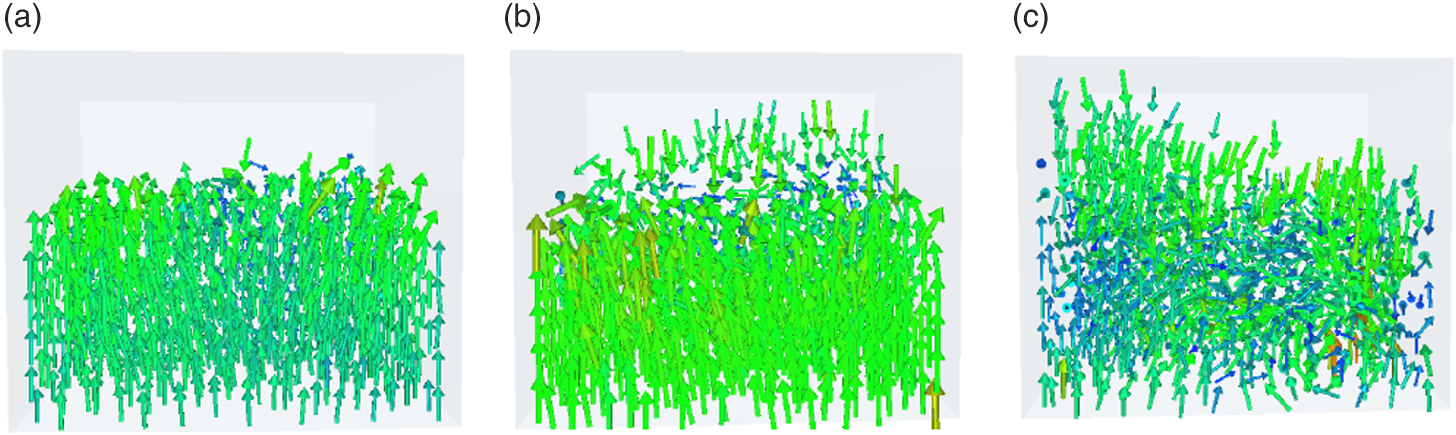
Mechanical model based on DEM
The DEM is a numerical method for solving discrete particle mechanics problems, commonly used to solve and analyze the motion laws and mechanical properties of discontinuous media. The system is treated as consisting of independent finite units, with each element in contact through points, lines, and surfaces. Under external excitation, mutual forces may occur between each element. Then, the acceleration is calculated using Newton’s second law, the velocity and displacement are calculated by integration. Finally, based on the results of calculation to update the state of the unit in the next step, new forces and moments will be generated. By using a time step iterative method, a loop is formed and continuously calculated, ending when the termination condition is reached.
During movement, contact forces are generated by collisions and friction between various units. The contact model, the core theoretical model of the DEM, directly determines the forces acting on the particles. This paper employs the Simplified representation of the contact model.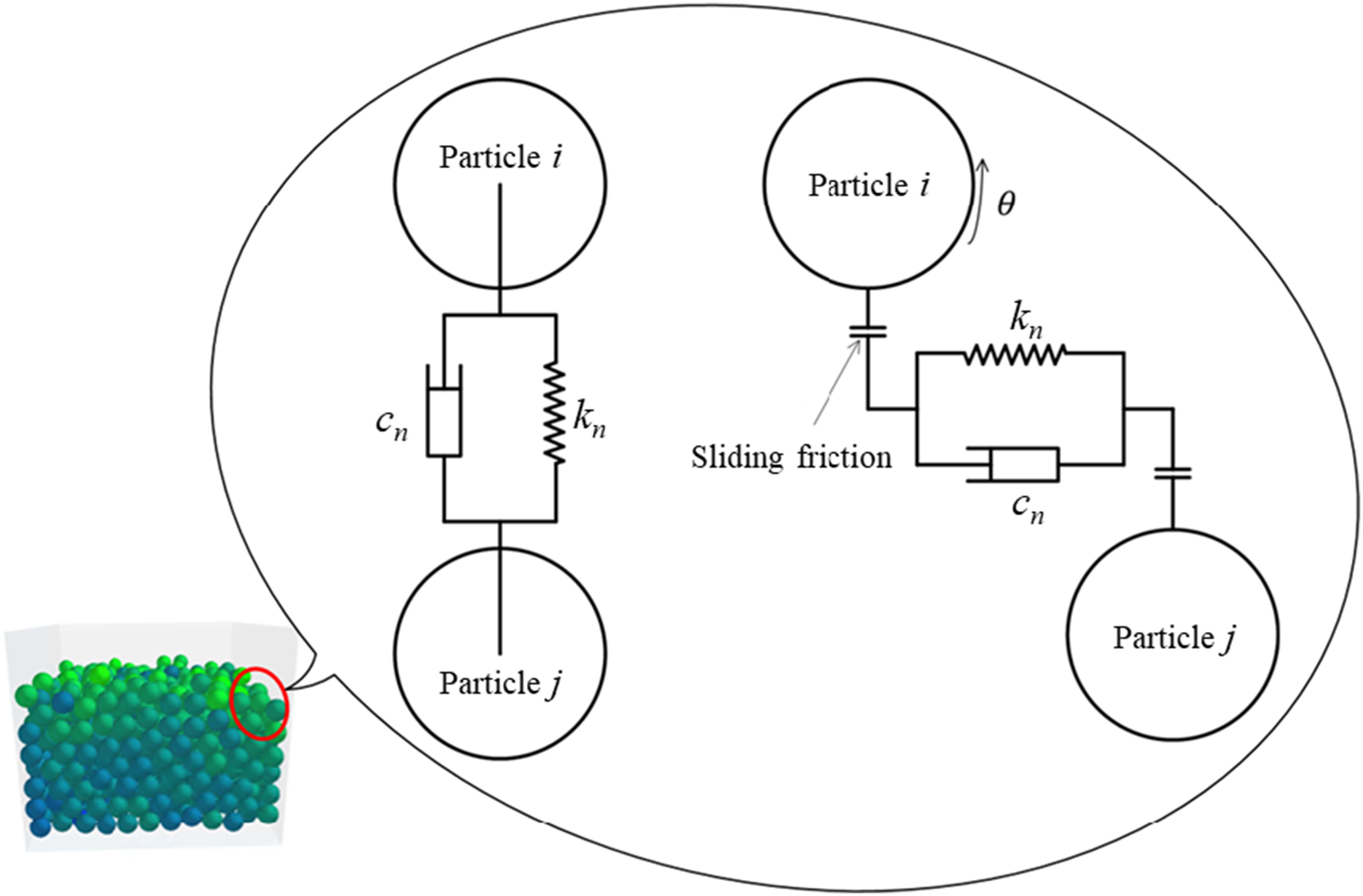
The normal contact force, tangential contact force, and moment of the particles can be expressed as
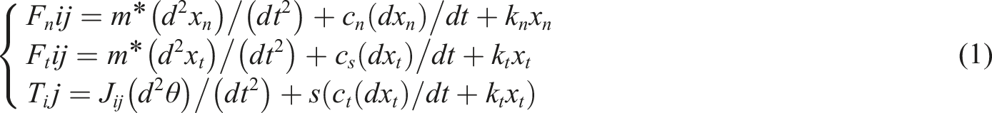
In equation (1):
Energy consumption model of particle damper
Particle damping vibration reduction technology dissipates energy through the friction and collision of filled particles. When the structure vibrates, the particle damper moves together with the vibrating component. The internal particles convert the vibration energy into thermal energy, sound energy, and other forms of energy through collision and friction, leading to energy dissipation and generating damping and vibration reduction effects. In the working process of particle dampers, the collision between particles and between particles and the container is one of the main ways of energy dissipation. This kind of spherical collision problem is usually analyzed using the classical Hertz theory in contact mechanics. During the collision process, there are two types of collisions: normal collisions and oblique collisions. The losses caused by normal collisions manifest as kinetic energy loss. In oblique collisions, there are both normal velocity and tangential velocity. The losses caused by the normal velocity are the same as those analyzed in the previous section for normal collisions. The tangential velocity will result in tangential displacement between particles and between particles and the container wall, leading to frictional losses.
The energy consumption during particle collision is calculated based on the kinetic energy loss of the two particles before and after the collision

The energy consumption in the process of particle friction is expressed as

The energy dissipated during the operation of particle dampers includes the kinetic energy loss from normal collisions between particles and between particles and the container wall, the energy loss from the normal velocity generated by tangential collisions, and the frictional energy loss caused by the tangential velocity from tangential collisions

In equation (4): m and n represent total number of collisions and frictions of particle dampers. The energy consumption equation shows that parameters such as particle mass, collision recovery coefficient, and number of particles are closely related to the level of energy consumption.
Simulation analysis of energy consumption
From the theoretical analysis, it is clear that there are several parameters that affect the energy consumption level. Therefore, in order to facilitate a reasonable analysis for the influence of parameters on energy consumption, the chapter uses a simulation method based on the DEM to simulate the mechanical behavior of particles.
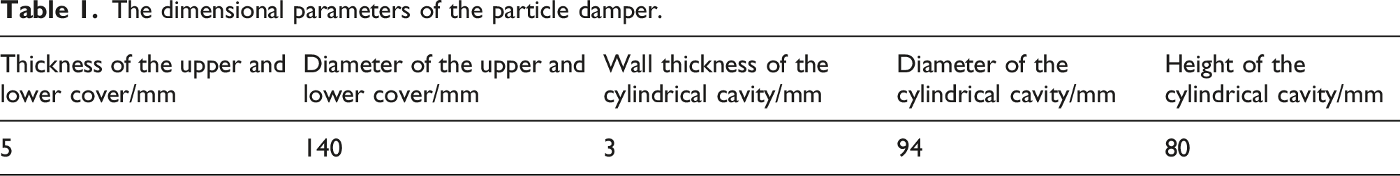
There are usually two types of particle damper structures: embedded structure and external structure. According to the structural characteristics of the ship’s vibration isolation platform, the external type is used, which is fixed by means of clamps. The specific structure and dimensional parameters are as shown in Figure 3 and Table 1. The main body adopts a cylindrical cavity structure. The structure of particle damper. The dimensional parameters of the particle damper.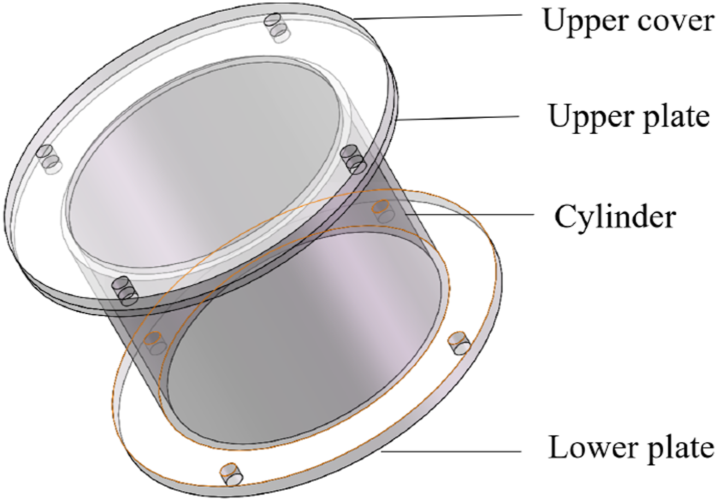
Analysis of the effect of particle materials
The parameters of particle material.
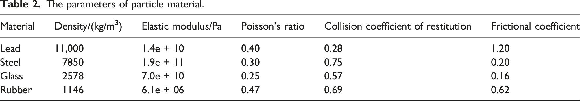
When setting the simulation parameters, all parameters except for the material parameters were kept the same. The container was filled with particles of 10 mm in size, the same filling rate, external excitation and simulation time were set and different material properties were assigned. The energy consumption data was counted and the energy consumption values are shown in Figure 4. Energy consumption with different materials of particle.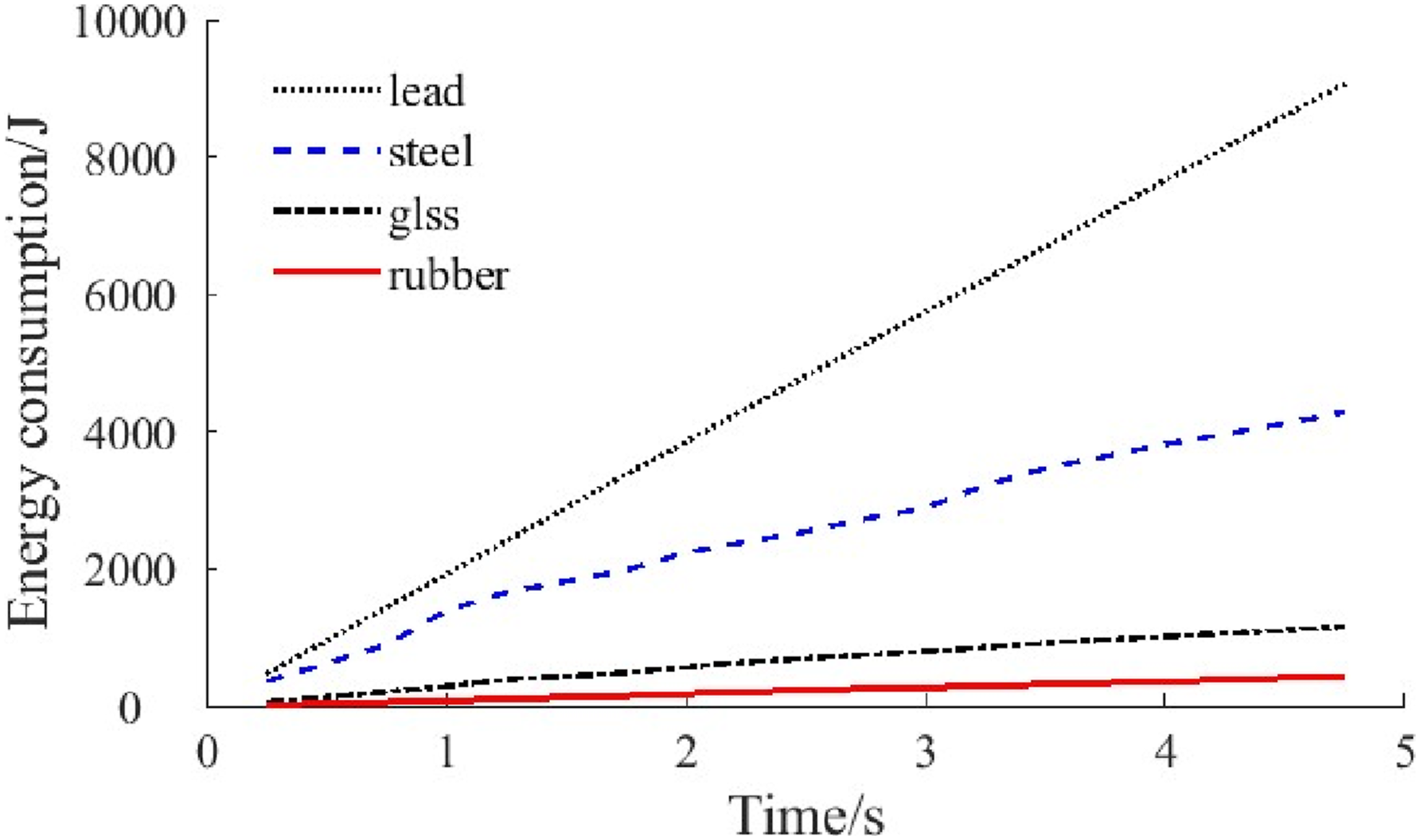
As shown in Figure 4, the energy consumption of the particle damper when filled with lead particles is the highest of the four materials. According to the analysis of particle material properties and energy consumption data, the density of particle material has the most important effect on energy consumption. So, denser materials are preferred when selecting materials. However, the problem with higher densities is that the additional mass becomes larger, and the size of the additional mass is sensitive in some engineering situations. Therefore, it is important to make a reasonable choice in relation to the actual situation.
Analysis of the effect of filling rate
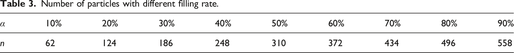
The filling rate, which represented by the ratio of volume of particles filled into the container to the volume of the container, is one of the most important parameters. The number of particles corresponding to different filling rates can be calculated using the following equation
In equation (5):
Number of particles with different filling rate.
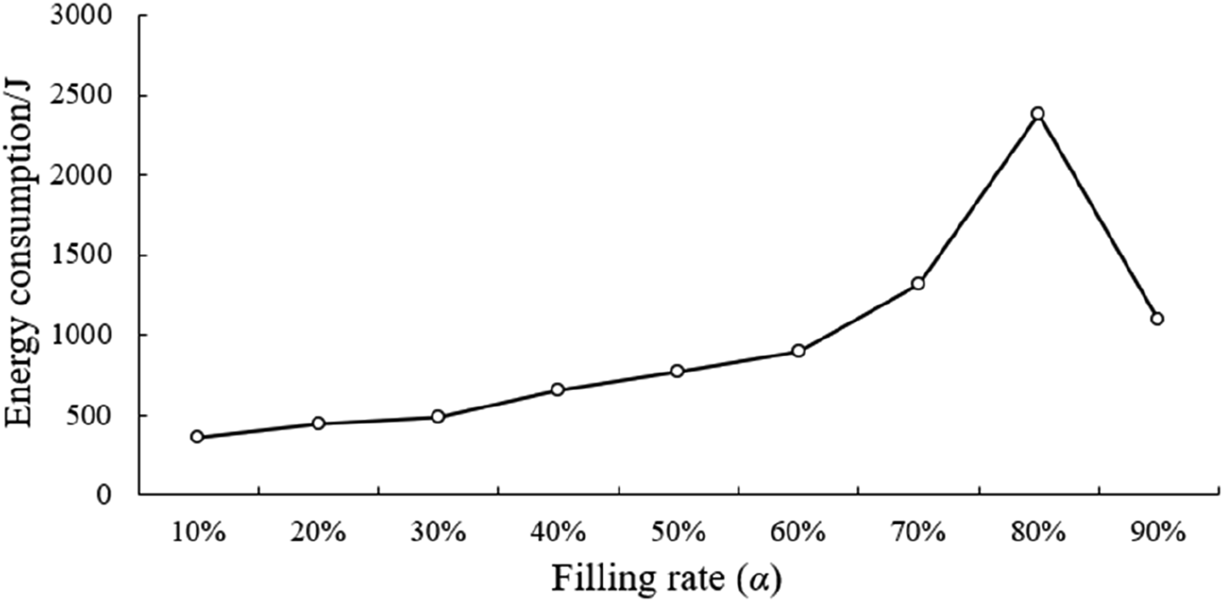
Energy consumption with different filling rate.
As shown in Figure 5, the energy consumption reaches a maximum near a fill rate of 80%. The analysis shows that the low number of particles at lower fill rates results in fewer collisions and friction between particles, and therefore lower energy consumption. When the filling rate is more than 80%, the number of particles is too high to provide sufficient movement space for particles, which reduces the number of collisions and friction, resulting in lower energy consumption.
Figure 6 shows the particle motion vector diagrams for filling rates of 60% and 90%. It can be seen that when the particle filling rate is low, the particles have a larger space for movement, allowing them to move freely. Therefore, the number of interactions between particles increases, resulting in greater energy consumption. When the filling rate is high, the particle movement space is severely restricted, and the particles agglomerate to move together. The particle activity is lower, affecting the number of collisions and friction, resulting in lower overall energy consumption. Based on the above analysis, the optimal filling rate is 80%. Particle motion under different filling rates. (a) R-70% (b) R-90%.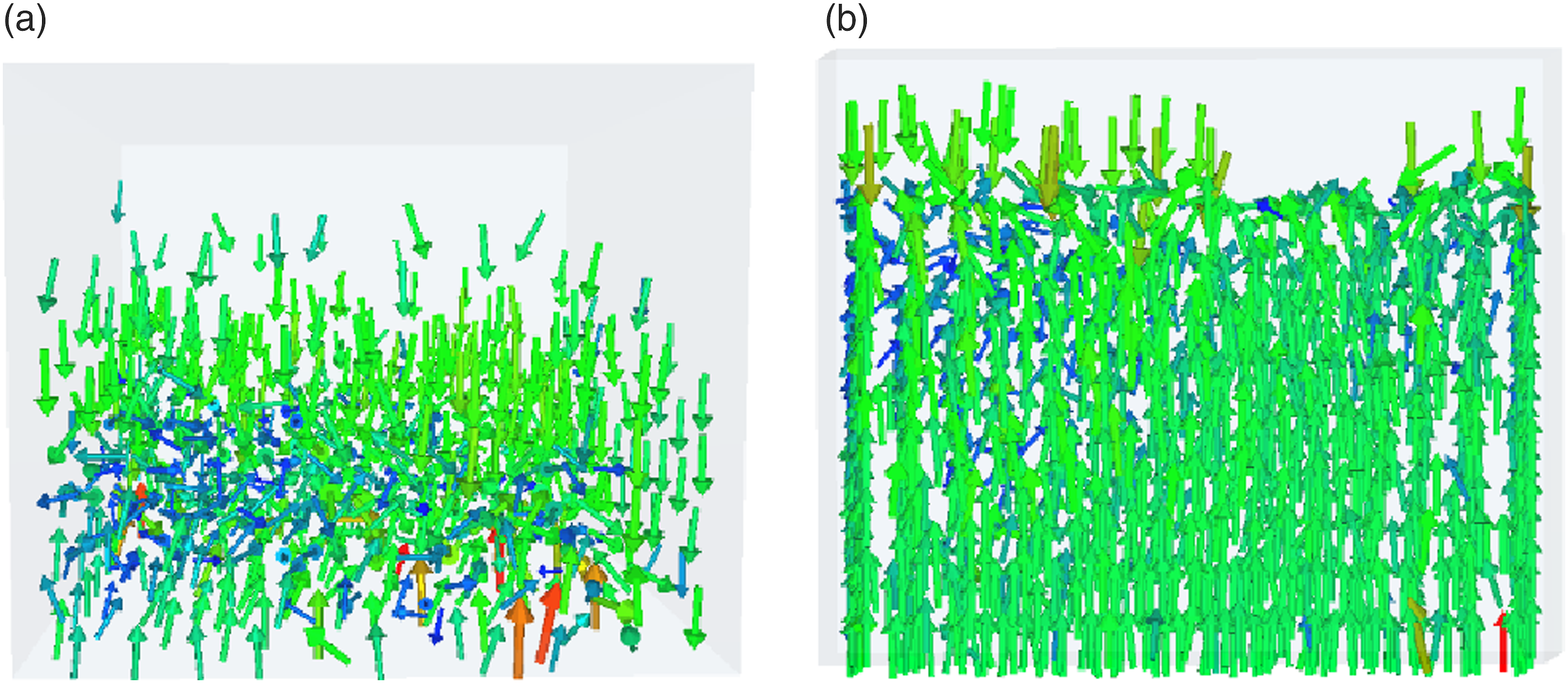
Analysis of the effect of particle diameter
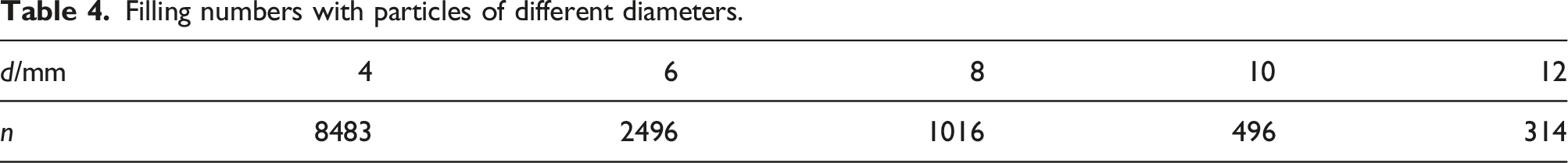
Filling numbers with particles of different diameters.
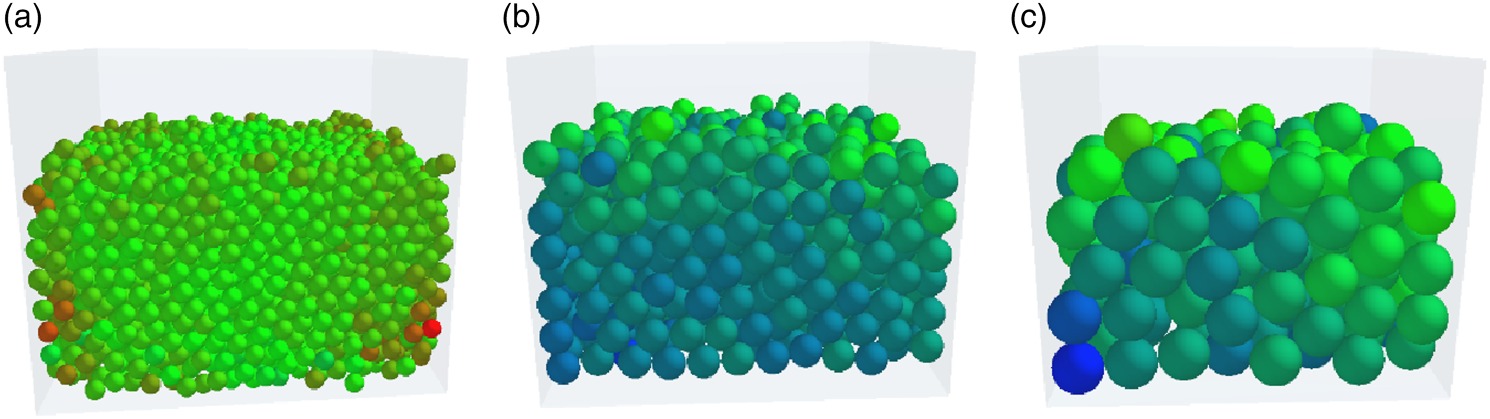
Particle filling state under three particle sizes. (a) d = 4 mm (b) d = 8 mm (c) d = 12 mm.
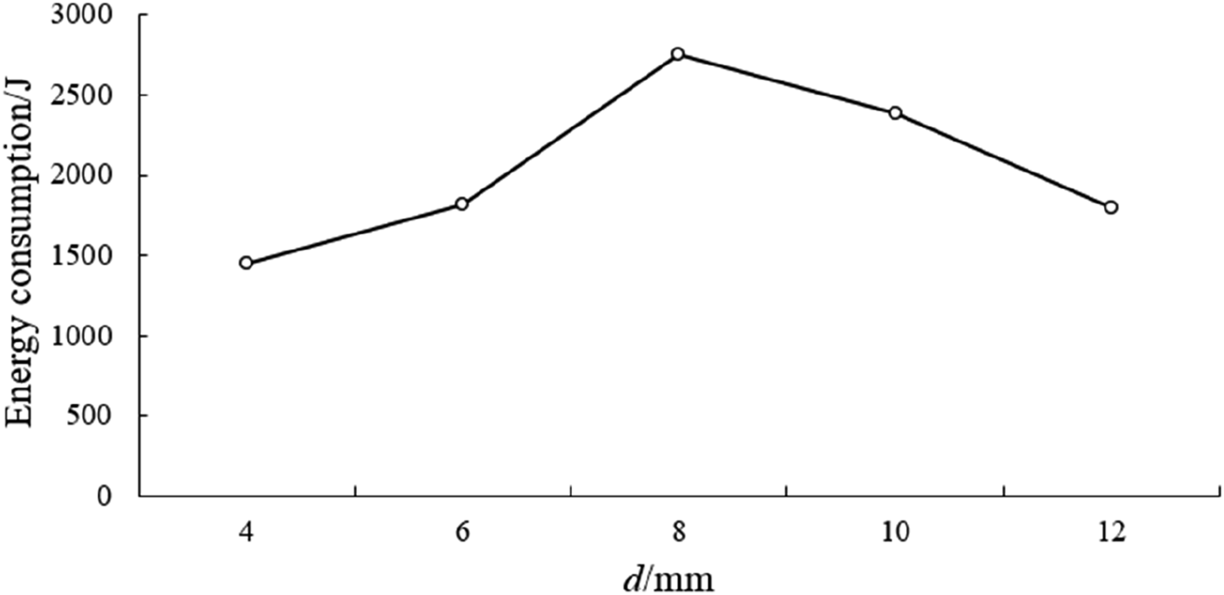
Energy consumption with different particle diameters.
As shown in Figure 8, the maximum energy consumption is achieved at a particle diameter of 8 mm, indicating that there is an optimum effect of particle diameter on energy consumption. The analysis shows that when the particle diameter is small, the kinetic energy of individual particles is also small, although the number of particle collisions and friction is high. Therefore, the energy that can be lost by the particle dampers is also smaller. When the particle diameter is too large, the kinetic energy and particle number are opposite to the above situation, which leading to a decrease in energy consumption.
Analysis of the effect of collision coefficient of restitution
As a physical parameter of particle materials, the collision coefficient of restitution (e) has a greater impact on the energy consumption of particle dampers. This coefficient, which is mainly determined by the material of particles and is independent of particle size and speed, represents the energy loss of particles before and after collision. When the e is large, the kinetic energy loss after collisions between particles is smaller and therefore increases the number of collisions with the rest particles, but the energy consumption by the particles in a single collision is small. The opposite result is achieved when the e is small. Therefore, it can be seen that there is an optimal value of 0.5 for this coefficient to affect the energy consumption level.
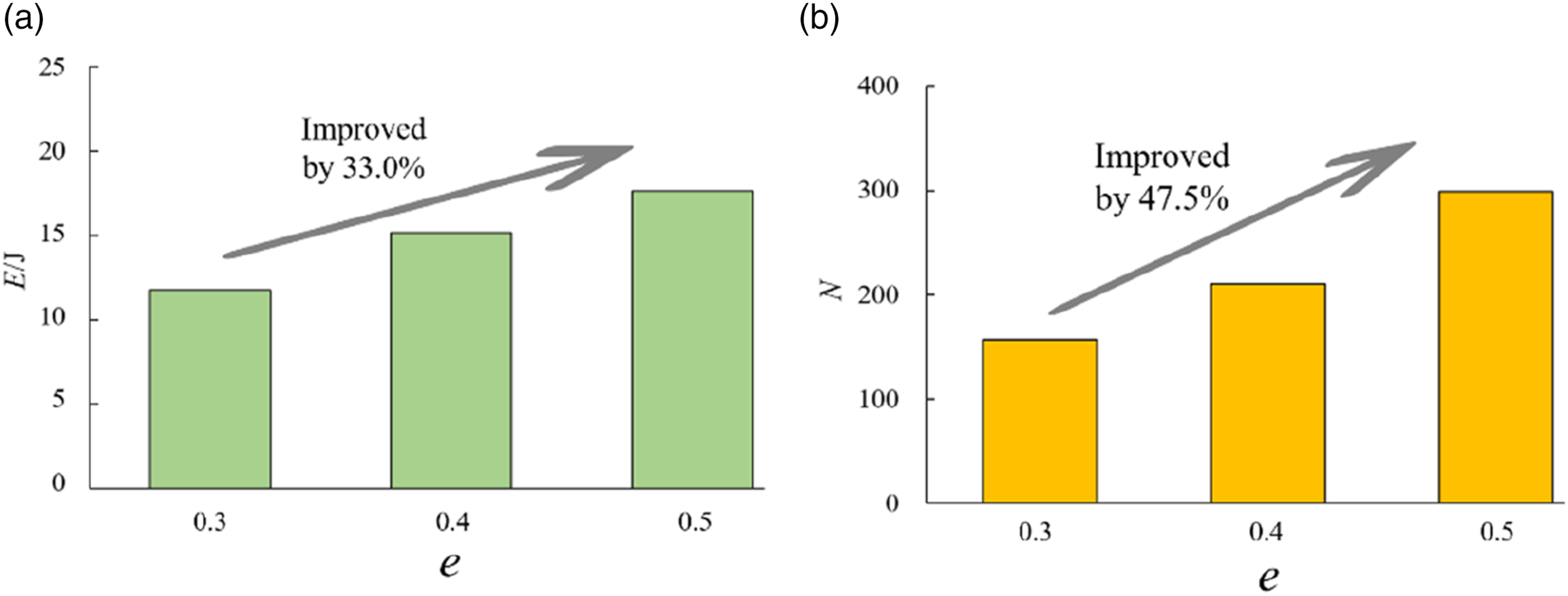
In order to obtain t an optimum value for the e for this time, the simulation parameters except the e were set to be the same, and the energy consumption was calculated when the e was 0.1∼0.7, respectively, and the results are shown in Figure 9. It can be seen that the energy consumption is not proportional to the e, but is greatest when the e is 0.5, which confirms the existence of an optimum value for the e. From Figure 10, it can be observed that when the restitution coefficient is 0.5, the average number of particle collisions (N) significantly increases compared to when it is 0.3. Although at this point, the kinetic energy of the particles (E) increases, resulting in a decrease in the energy consumption per collision, overall, energy consumption still increases. This proves the accuracy of the theoretical analysis mentioned above. Energy consumption with different e. Number of collisions and kinetic energy of particles with different e. (a) E-e (b) N-e.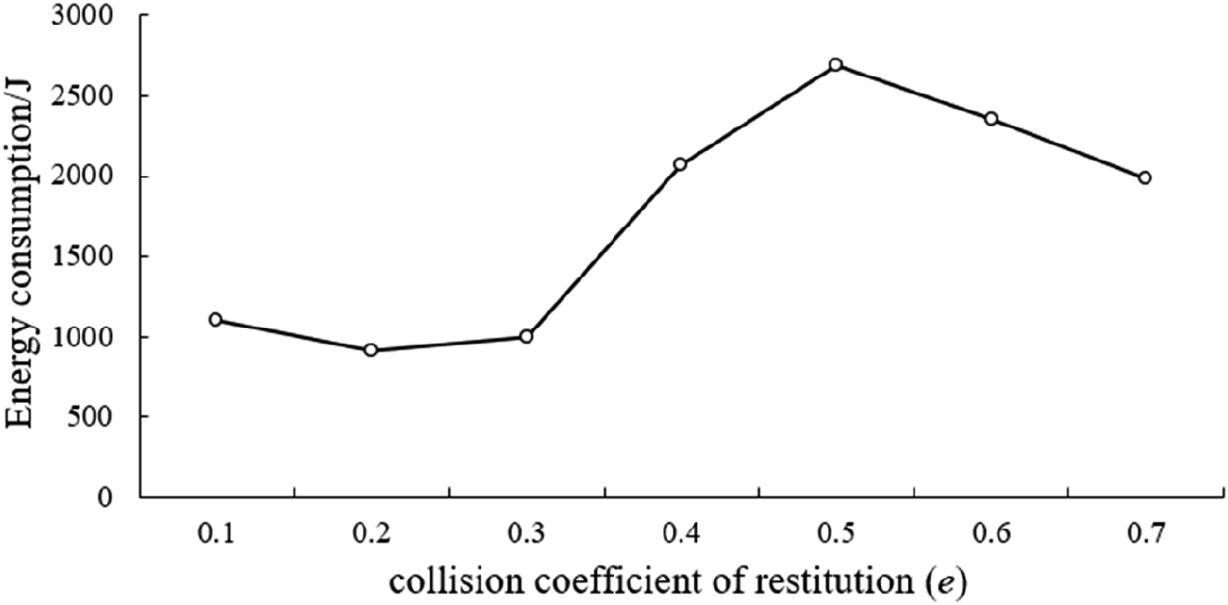
Experiments on the influence of parameters on vibration damping performance
In this experimental study, the vibration isolation system was used as experimental platform, and the processed particle dampers were installed on vibration isolation platform to study the vibration damping effect under the action of the particle dampers. The experimental results are also verified with the simulation calculations to prove the effectiveness of particle dampers.
As shown in Figure 11, the vibration damping experimental setup mainly consists of the vibration isolation platform, vibration signal generation, and acquisition system and particle dampers. The schematic diagram for this experiment is shown in Figure 12. The vibration reduction experimental platform with particle dampers. The schematic diagram of experimental principle.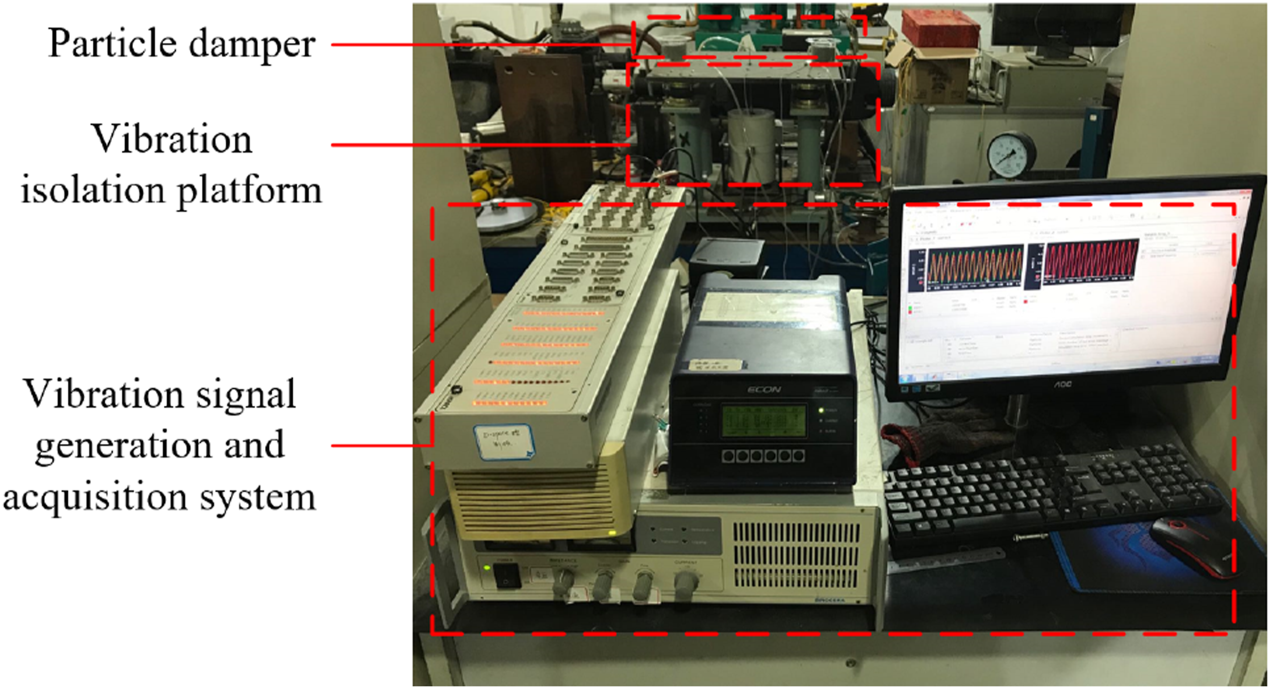
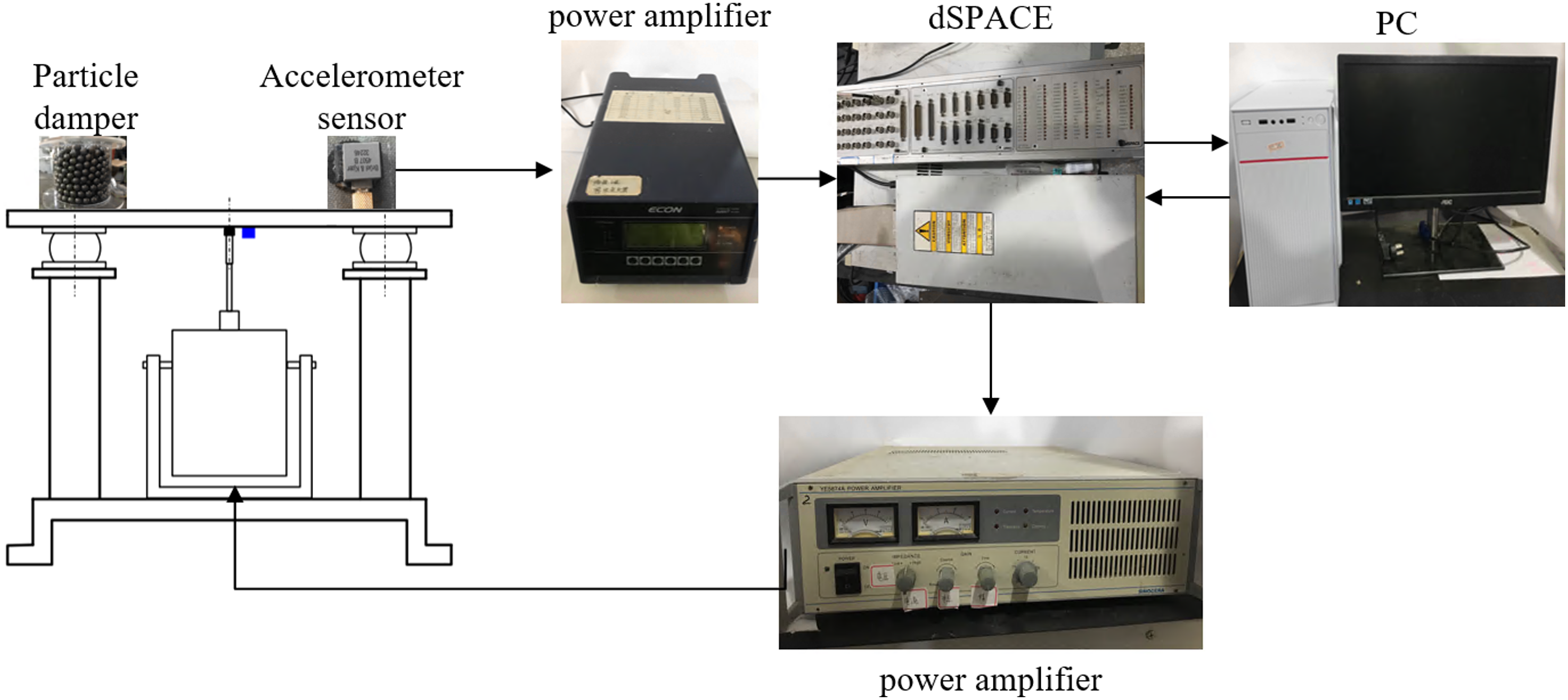
As shown in Figure 13, the vibration isolation platform consists of a base, electromagnetic actuator, pneumatic isolator, raft, and acceleration sensor. On the support frame of the base, four pneumatic isolators are installed, and an electromagnetic actuator is installed at the center of the base plate. The four pneumatic isolators are rigidly connected to the lower surface of the raft via flanges, and their installation positions are evenly distributed at the four corners of the raft. The connecting rod of the electromagnetic actuator is rigidly connected to the raft through connecting sleeve, with the axis of the connecting rod parallel to the pneumatic isolator. The position where it is rigidly connected to the raft is located at the geometric center of the raft. Physical image of the vibration isolation platform. (a) Installation physical diagram of the particle damper (b) physical installation diagram of the vibration isolation platform.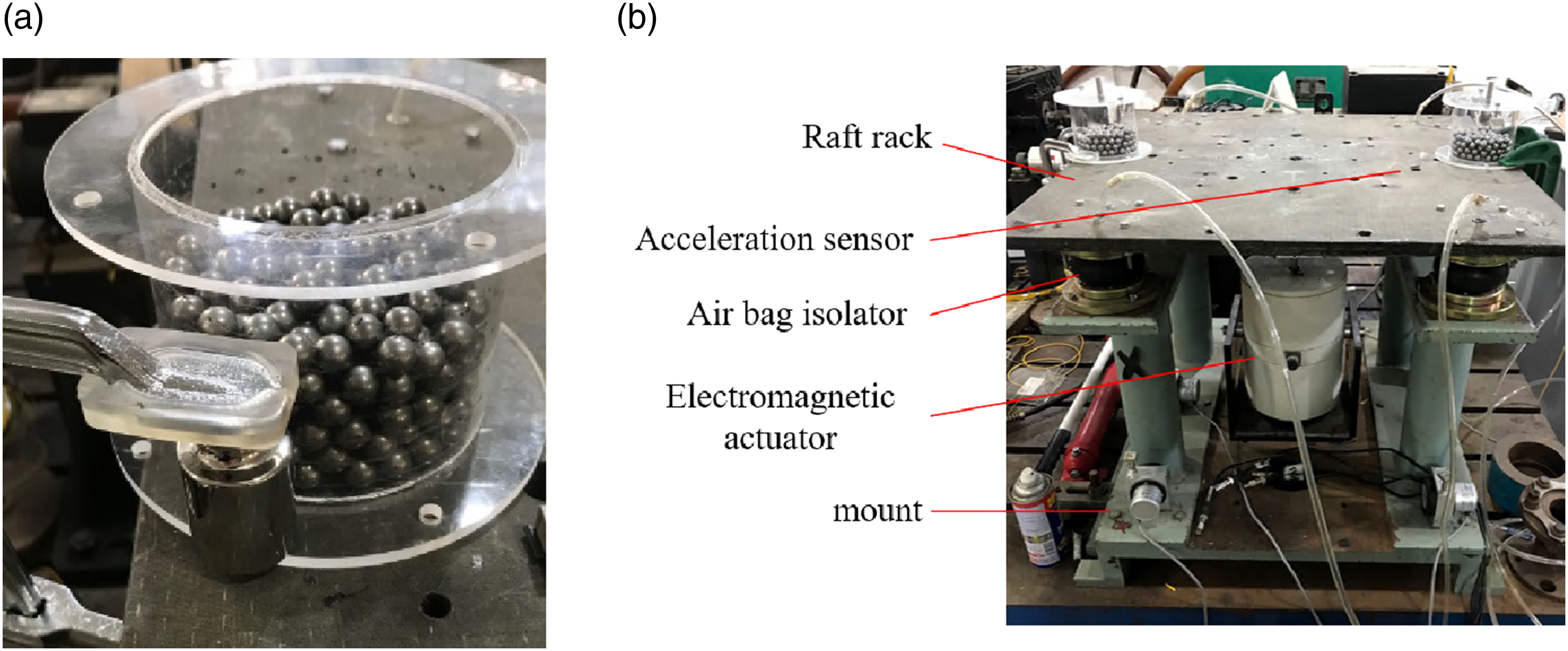
Vibration characteristics experiments on vibration isolation systems
This section of the experiment analyzed the damping effect of particle dampers at different excitation frequencies. The first natural frequency of the isolation platform obtained is 140 Hz through frequency response characteristics experiments. In order to analyze the vibration characteristics, the excitation signal frequency range was set to be 110 Hz ∼ 170 Hz, with an interval of 5 Hz. The signal was collected through acceleration sensor. Three sets of experiments were designed to verify the vibration suppression capability of the particle dampers: with the particle dampers on the vibration isolation platform, with the equivalent mass on the vibration isolation platform, and without any mass on the vibration isolation platform (None). The results of the experiment are shown in Figure 14. Maximum acceleration response with different excitation frequency.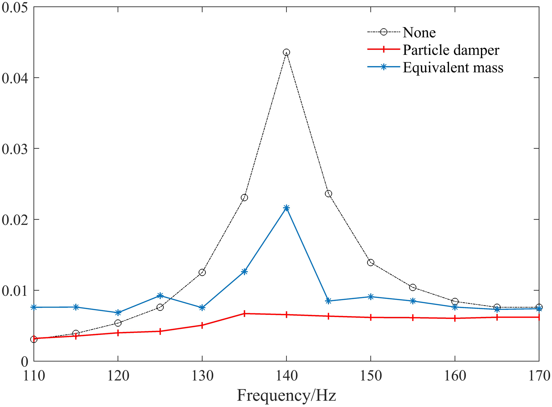
At excitation frequencies of 130 Hz, 135 Hz, 140 Hz, 145 Hz, and 150 Hz, the particle dampers produce damping effects of 33%, 47%, 70%, 25%, and 32%, respectively. The best damping effect is achieved at an excitation frequency of 140 Hz, confirming the view that particle dampers are most effective at the resonance peak of the system.
Experiments on the influence of particle damper parameters
Material
The materials chosen for this experiment include both commonly used metals and non-metals, metals including lead and carbon steel, and non-metals including glass and rubber. During the experiment, ensure that all parameters except for the particle material are the same, and the results are shown in Figure 15. Acceleration response with different materials of particle.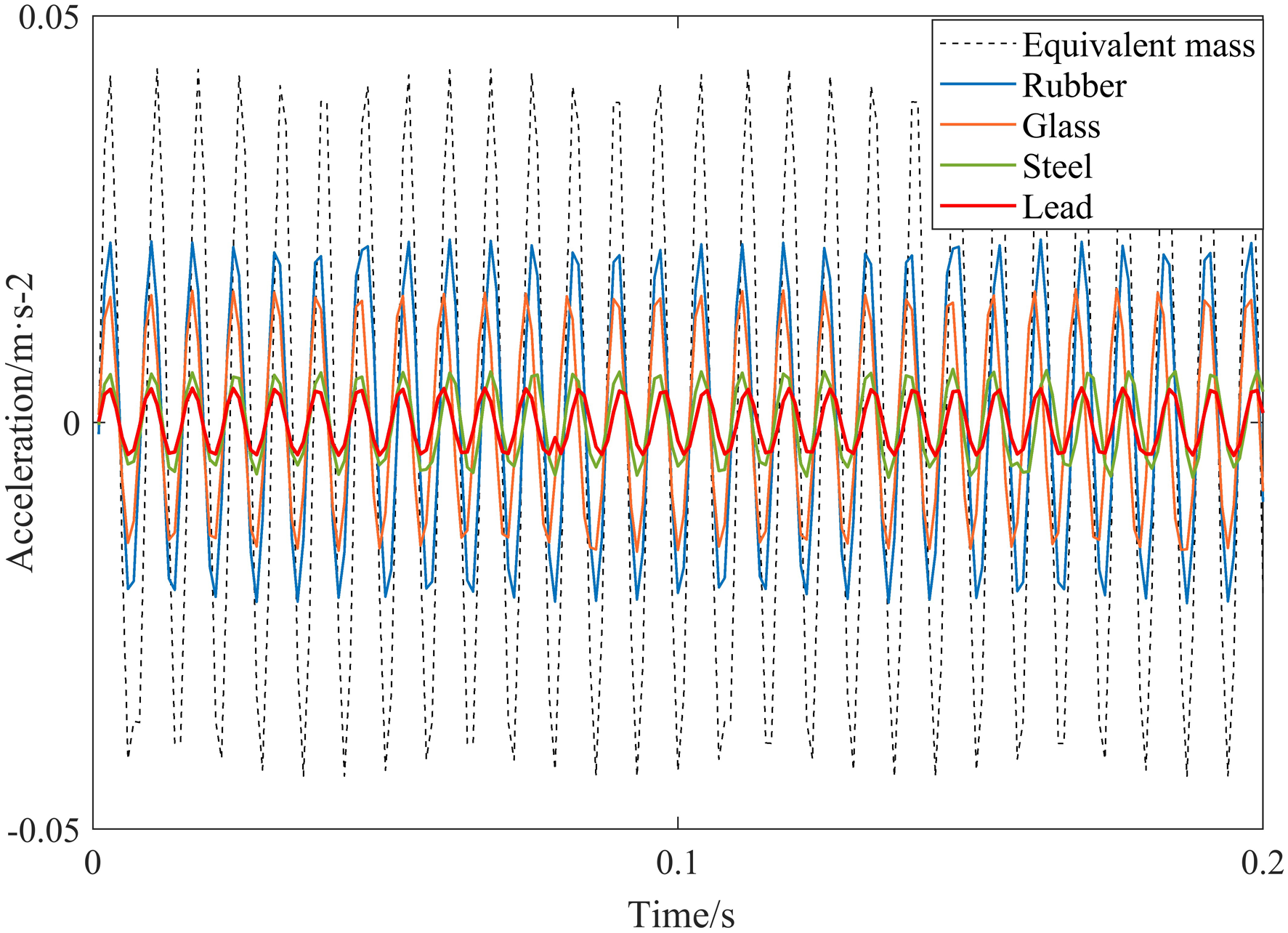
The acceleration insertion loss is selected as the evaluation index for the vibration reduction effect of particle dampers. The definition of acceleration insertion loss is: 20 times the commonly used logarithm of the ratio of the acceleration response value (A
1
) of the controlled object before vibration reduction to the acceleration response value (A
2
) after vibration reduction before and after applying the particle damper, as shown in equation (6)
The acceleration response of the four materials is significantly lower than that of the equivalent mass, indicating the excellent vibration reduction performance of the particle damper. When the filling material is lead, steel, glass, and rubber, the vibration acceleration amplitude decreases by 20.2 dB, 16.4 dB, 8.5 dB, and 5.7 dB, respectively. It can be seen that the vibration reduction effect is best when filled with lead particles. The trend of experimental and simulation results is consistent, and the simulation and experiment have been mutually verified. Therefore, when selecting particle materials in practical applications, it is recommended to prioritize materials with high density under the comprehensive analysis of experimental and simulation results.
Filling rate
In the experiment, it was ensured that all parameters were the same except for the filling rate(R), and the filling rate was changed from 30% to 100%. And differences in mass due to different filling rates were supplemented by counterweights. The experimental data are shown in Figure 16. Acceleration response with different filling rates. (a) R: 30%∼40% (b) R: 50%∼60% (c) R: 70%∼80% (d) R: 90%∼100%.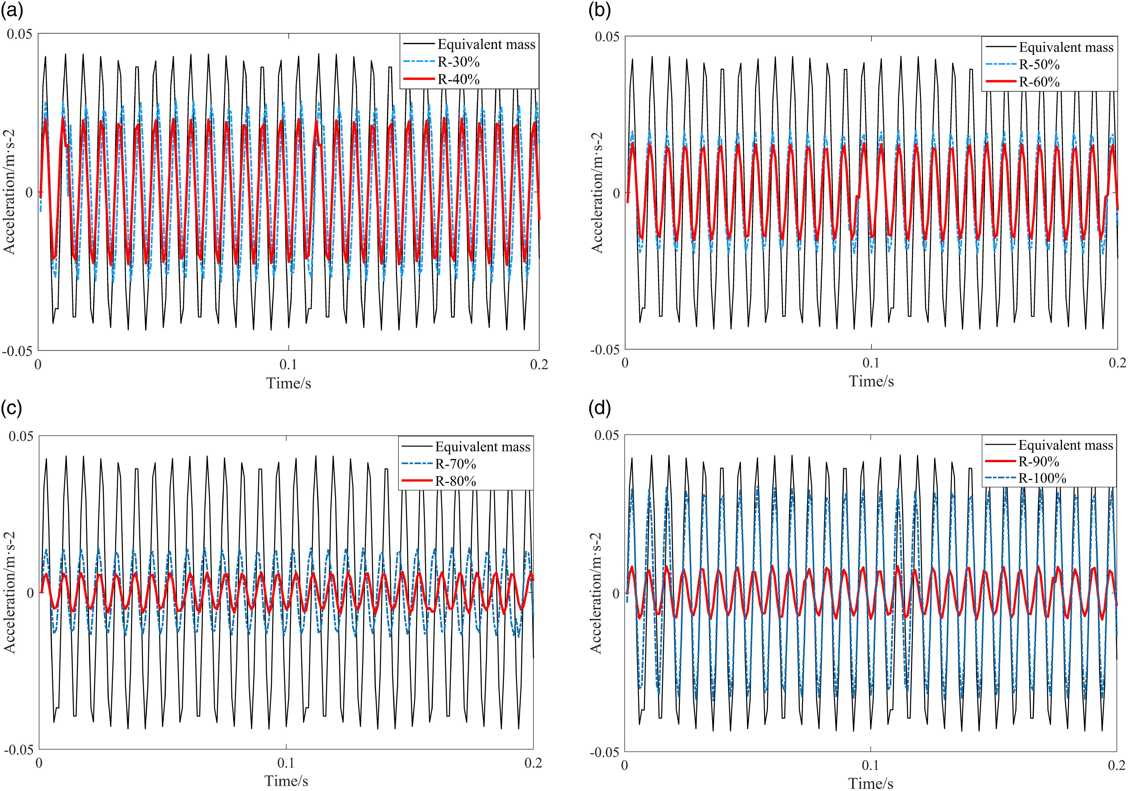
It can be seen that the A at different fill rates is significantly less than at equivalent mass, and the A are reduced by 3.6 dB, 5.4 dB, 6.8 dB, 8.7 dB, 9.7 dB, 16.4 dB, 14.2 dB, and 2.2 dB, respectively. As the filling rate increases, the vibration reduction effect of the system shows a trend of first increasing and then decreasing. The optimal vibration reduction effect is achieved when the filling rate is 80%, which is consistent with the trend of energy consumption simulation results. Based on the experimental results and simulation data, it is recommended to prioritize particle filling rates around 80% in practical engineering applications.
Particle diameter
In order to investigate the effect of particle diameter on damping performance, five diameters of particles were selected for the size of the particle dampers: 4 mm, 6 mm, 8 mm, 10 mm, and 12 mm. During the experiments, all parameters except particle diameter were guaranteed to be the same and only the particle size was changed in each experiment. The results are shown in Figure 17. Acceleration response with different particle diameters. (a) d: 4 mm∼8 mm (b) d: 10 mm∼12 mm.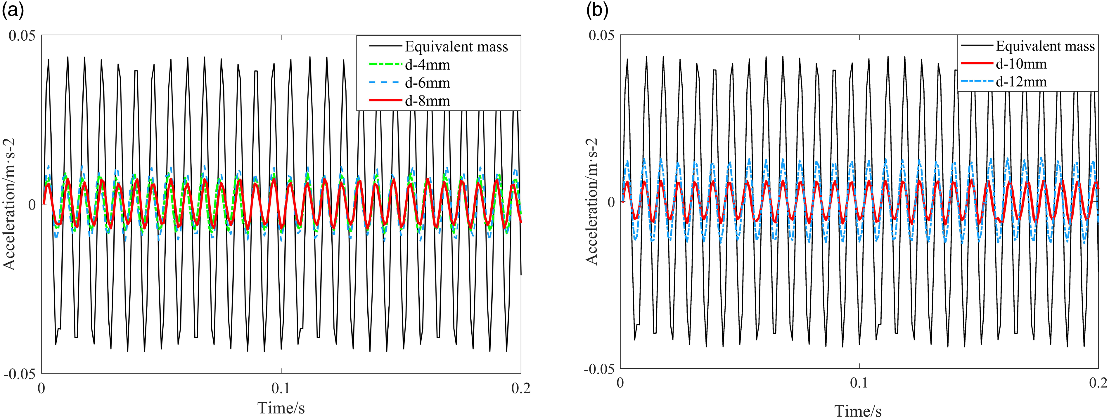
When filled with particles of different diameters, the A is significantly less than at equivalent mass. The A are reduced by 10.4 dB, 11.6 dB, 15.1 dB, 16.4 dB, and 13.5 dB, respectively. Due to the discrete unit simulations with a 2 mm diameter interval used in this study, there may be slight differences between the experimental results and simulations. However, the overall trend remains consistent, and the differences are within an acceptable range. It can be concluded that the optimal ratio of particle diameter to the outer diameter of particle damper chamber is between 0.085 and 0.15.
Optimization analysis of impact parameters
The previous analysis shows that the energy consumption mechanism of particle damper is complex and there are several parameters that affect the damping performance. When using single variable analysis method to the energy consumption, it is difficult to obtain the optimal parameter combination corresponding. In addition, when the number of particles in practice is large, the complexity of the simulation using the DEM can be high and the calculation time can increase dramatically, thus greatly affecting the efficiency. Therefore, the response surface methodology (RSM) will be used to fit the relationship between the variables and obtain the optimum parameters, and also to guide the design of the particle dampers through theoretical calculations instead of simulations to improve efficiency.
Response surface methodology
The RSM is an optimization method based on statistics, which aims to determine the best combination of parameters by seeking quantitative laws between objective and impact parameters.32,33 The central combination design method was used in this analysis because of the presence of continuous variables. The mathematical model between the response and the variables is constructed by fitting a multiple quadratic regression equation.
34
And 
In equation (7),
The RSM evaluates parameters and their interactions by designing a continuous variable surface model with fewer groups than the orthogonal experiments. The calculation process is generally divided into three steps: parameters selection, optimal range finding, and optimization. The specific process is shown in Figure 18. The implementation steps of RSM.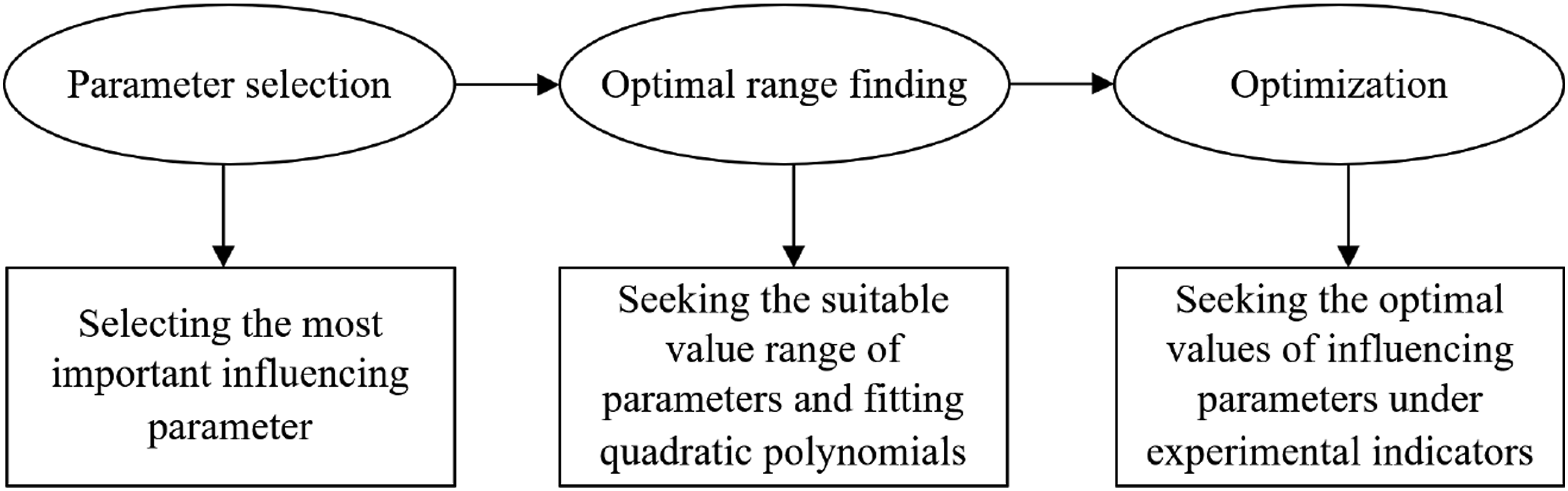
After using the RSM for modeling, residual analysis method will be used for analysis, and the reliability and accuracy of the model will be verified by drawing the probability distribution map of residual within the model. The RSM allows for the fitting of a fitted relationship between the influencing parameters and the target variables, which can effectively address and guide the design of multivariate structures.
Scheme design and result analysis
The encoding table of RSM.
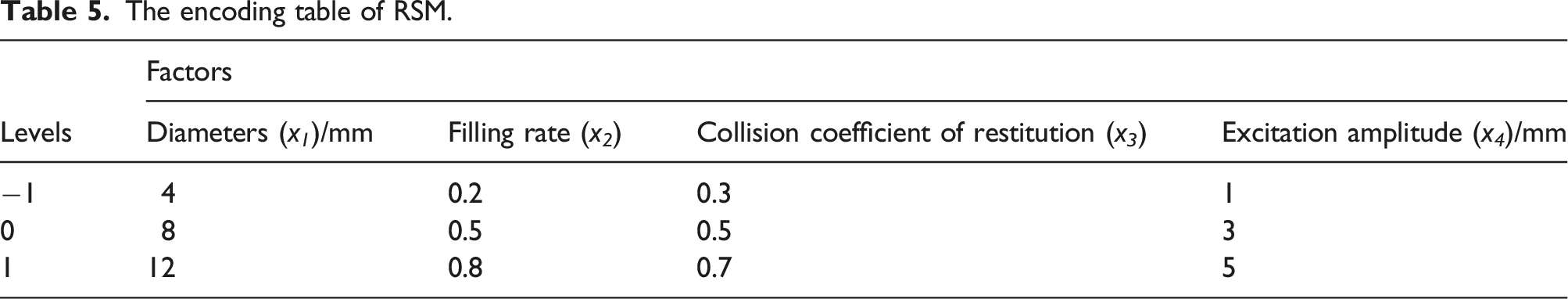
Different combinations of parameters were generated according to the central combination design method, for a total of 25 groups. Then, energy consumption simulations were carried out separately for different combinations of parameters and the energy consumption values (E) were calculated. Finally, the equations were fitted by RSM to obtain the quadratic relationship between each parameter and energy consumption as shown in equation (8).
The eigenvalue of RSM model.
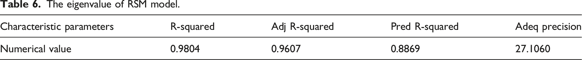
In order to further analyze the accuracy and reliability of the established model, residual method was used for analysis. The relationship between the true and predicted values of energy consumption is shown in Figure 19(a). And it can be seen that the data overlap is relatively high. Figure 19(b) shows the residual between the true and predicted values of energy consumption. The standard deviation ( The results of residual analysis. (a) Simulation and predicted values of E. (b) The residual curve of between true and predicted values of E.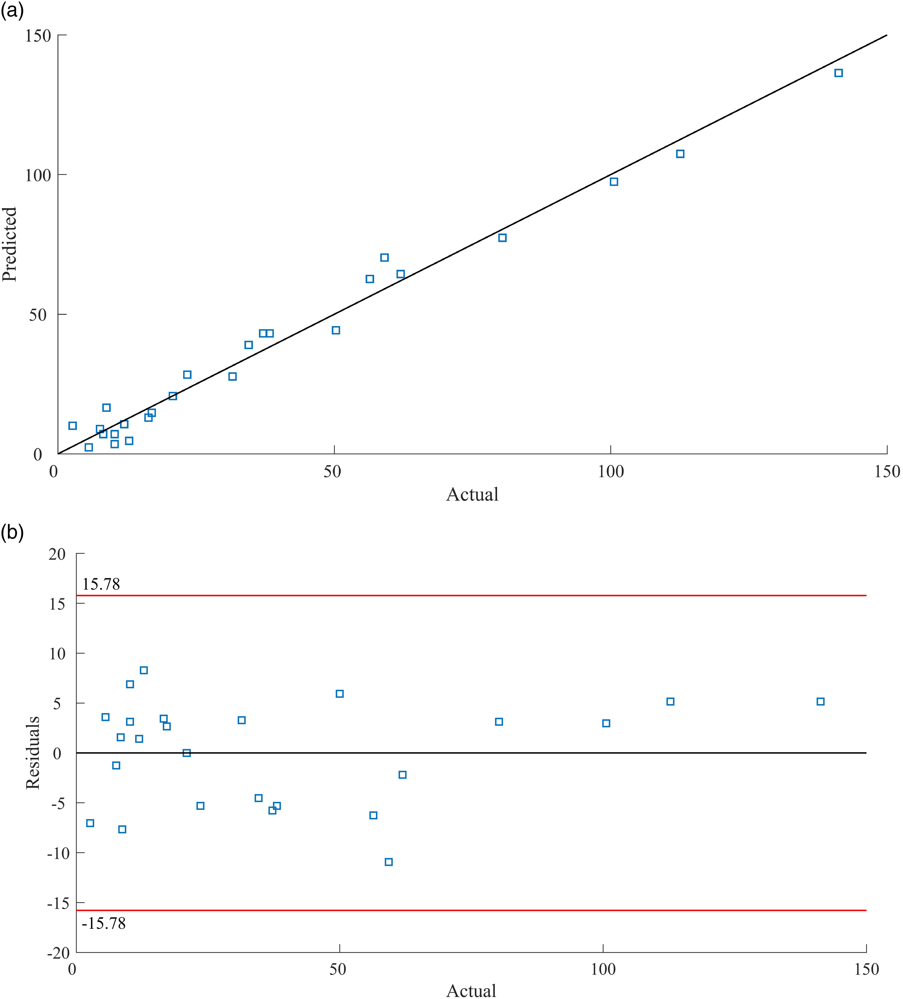
The error analysis results of model.
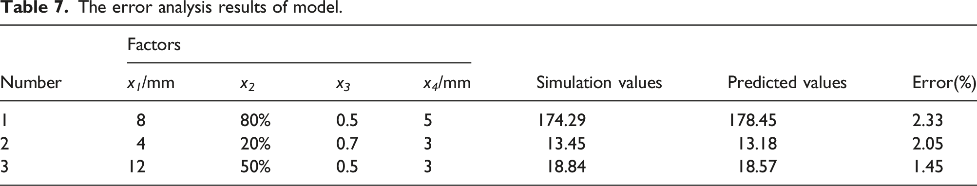
As shown in Table 7, the predicted energy consumption results using the RSM model are less inaccurate than those calculated by the DEM simulation, further demonstrating the accuracy and reliability of this method. In summary, the RSM can be used as a guide to find the optimum energy consumption parameters of particle damper.
Conclusion
This paper takes the ship vibration isolation system as the research object and in-depth investigates the influence of different parameters such as material properties and particle diameter on the energy consumption and vibration reduction performance of the particle damper, using a calculation model for energy consumption of the particle damper and a combination of simulation calculation and experimental research.
For the particle damper described in this paper, among the material performance parameters, density has a significant impact on the vibration reduction effect. Therefore, when conditions permit, materials with higher density should be chosen as a priority. For the material performance parameter of coefficient of restitution, a value around 0.5 is considered optimal. The optimal damping effect is not achieved with the highest possible particle filling rate. Instead, the best damping effect is achieved at around 80% filling rate. The ratio of particle size to the outer diameter of the particle damper cavity is optimal when it falls between 0.085 and 0.15 for better damping effect.
Finally, the energy consumption of the particle damper was analyzed using RSM to establish a mathematical model with the four parameters mentioned above. The accuracy and reliability of the model were verified through residual analysis, and it was found that there was minimal error between the simulation calculations and the model’s predicted results. Using RSM can provide guidance for the structural parameter design of particle dampers, and it offers a direction for future research and practical engineering optimization.
Footnotes
Declaration of conflicting interests
The author(s) declared no potential conflicts of interest with respect to the research, authorship, and/or publication of this article.
Funding
The author(s) disclosed receipt of the following financial support for the research, authorship, and/or publication of this article: This work was supported by the National Natural Science Foundation of China (No. 51879209), the Fundamental Research Funds for the Central Universities (WUT: 2021IVA117) and the Fundamental Research Funds for the Central Universities (WUT: 2021CG004).
Data availability statement
The data used to support the findings of this study have been included within the article.