
Abstract
Noise reduction in various industrial and building systems such as ventilation ducts, vehicles, wind tunnels, and test facilities for jet engines, automobiles, and factories has always interested engineers, especially the problematic noise reduction at low frequencies. This problem is even more important with passive silencers, which require absorbent materials and more space. Passive silencers include reactive and dissipative silencers. Among reactive silencers, Helmholtz resonators, expansion chambers, flute-like, drum-like, and plate silencers have proven effective at low frequencies. Combining some of these silencers with a dissipative silencer, called a hybrid silencer, can achieve excellent performance at a wide range of low to high frequencies. In these silencers, the reactive part reduces noise at low frequencies, and the dissipative part reduces noise at medium and high frequencies. The aim of this work, which focuses more on experimental studies, is to introduce the mentioned silencers, investigate the presented methods to improve the performance of these silencers at low frequencies, and offer the practical advantages and disadvantages of these methods.
Introduction
Noise reduction has a long history in various industries, such as construction, aviation, and factories. An example is Tucker’s specialized research on noise in civil aircraft and methods to eliminate it. In this research, 1 it is proposed the use of cotton woolen plugs as hearing protection, which could only absorb sound at high frequencies, while acknowledging the annoying low-frequency vibrations and the harmful effects of noise at all frequencies on the human ear. Low frequencies usually refer to the range from 20 to 200 Hz.2–5 Although different references have considered different ranges for low frequencies,6–8 some references assume up to 250 Hz,4,9 and others assume up to 500 Hz. Low-frequency noise sources include both natural sources such as wind and ocean waves and man-made sources such as all types of land, air, and rail vehicles, industrial types of machinery such as engines, pumps, compressors, turbines, valves, air conditioning and ventilation systems, and many other.6,10
The study of silencers as devices for noise attenuation has been the subject of research for nearly six decades. These studies often focus on improving the performance of silencers and their design methods. Improving the performance of silencers at low frequencies is one of these topics. The importance of this topic becomes even more apparent when one understands the harmful effects of low-frequency noise on the human body. Harmful physiological effects such as impairment of rhythm and respiratory rate, changes in systolic rhythm, changes in blood and endocrine glands, and disturbances in the central nervous system,11–14 as well as harmful effects on mental performance, are among these undesirable things.2,15 In addition, noise at low frequencies, especially in the octave bands of 64 and 31 Hz, causes unpleasant vibrations of light structures and subsequent destructive effects.16,17
Noise reduction at low frequencies is achieved by two active and passive methods.
18
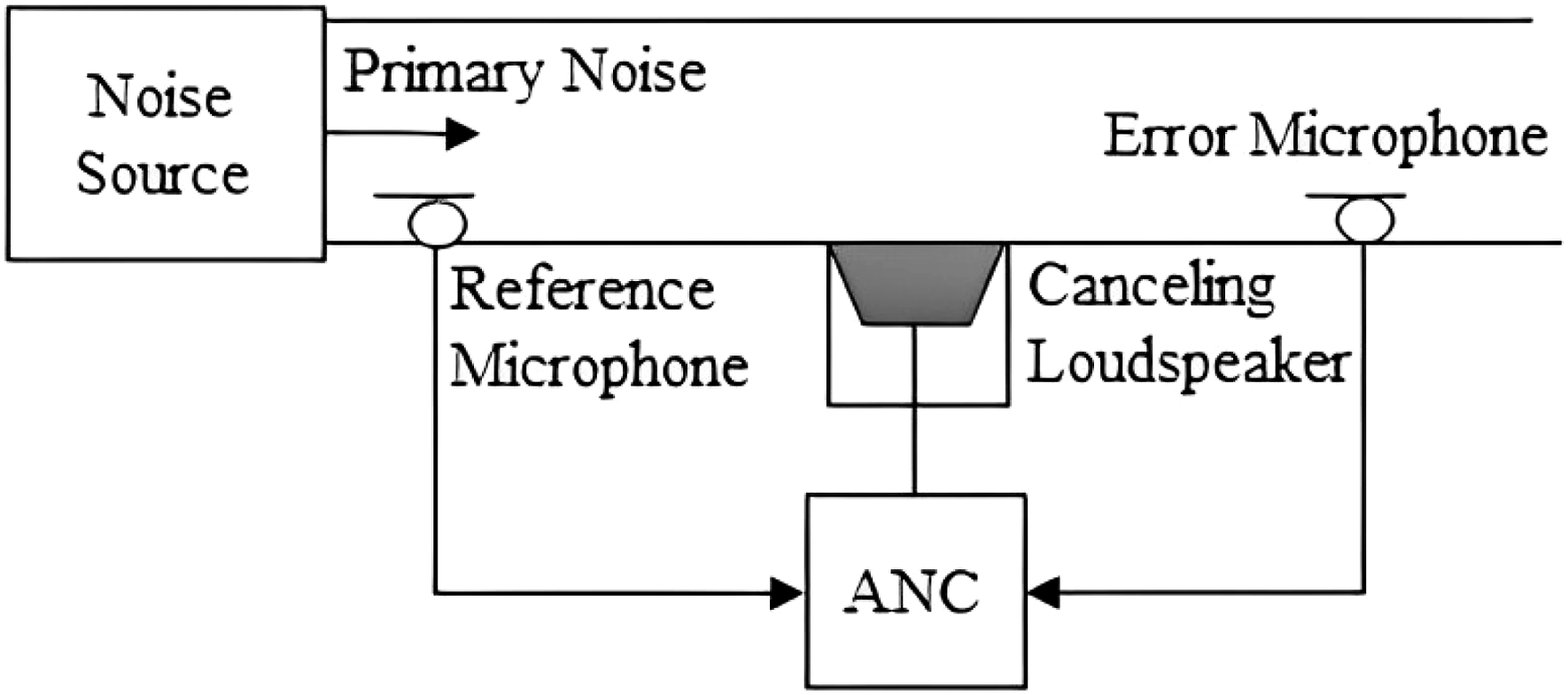
In active noise reduction, absorbent materials are not used, but an opposite noise is generated and mixed with the primary noise. First, the primary noise detected by an input microphone is processed in the controller and then fed to the system to remove the primary noise. The noise reduction is continuously optimized by an error microphone that sends information to the controller (Figure 1).
19
Many research papers have addressed active noise control and its application in various industries.20–23 Applications of active noise control include noise reduction in air conditioning ducts
24
and industrial blower systems, noise control of electrical transformers,
25
low-frequency tonal noise reduction in turboprop aircraft,26,27 noise reduction of naval vessels,
28
and many other cases. The advantage of the active method over the passive one is the reduction of pressure drop and the absence of absorbent material, especially in the ducts of air conditioning systems, which minimizes the possibility of mold growth.
19
Despite the many uses and advantages of active noise reduction, the complexity of the sound field especially in turbulent flow, multiple noise sources in one location, and the time constraints on the controller’s processing and fabrication of the noise reduction make the use of this method limited and most times impossible. Turbulent flow noise and acoustic feedback can be cited as two fundamental problems of active noise control. Turbulent flow noise sensed by microphones reduces the coherence between the error microphone and the reference microphone, resulting in a reduction in performing active noise control.
29
An example of acoustic feedback is the secondary signals generated in the loudspeaker, which move toward the reference microphone and reduce system efficiency.30,31 Active noise control system in a duct.
3
The most common method of noise reduction is the use of passive (reactive, dissipative, and hybrid) silencers. To better understand the different types of passive silencers and select the most suitable silencer for specific noise reduction requirements, the branching classification tree of Figure 2 can be used. It should be noted that the classification tree provided is a general representation and may not include all possible designs or variations of passive silencers. By classifying passive silencers into reactive, dissipative, and hybrid types, we can further distinguish various designs based on specific characteristics. The branching classification tree of passive silencers.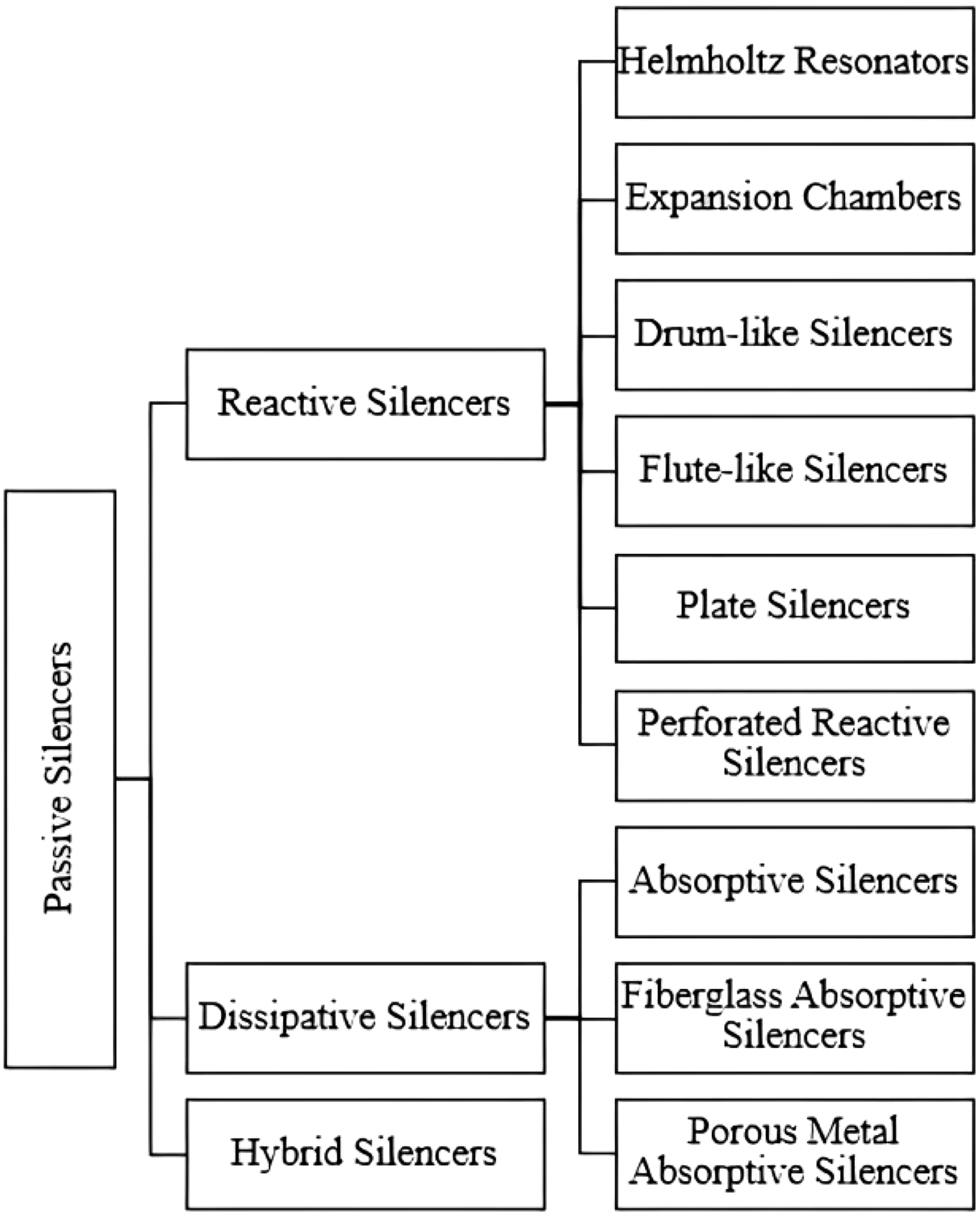
Reactive silencers comprise several pipe segments connected in one or more chambers. They lead to sound reduction by reflection or expansion of sound waves with corresponding self-destruction. 32 While the main text will focus primarily on reactive and hybrid mufflers, given their extensive applicability and significant contribution to noise reduction, it’s important to also briefly discuss dissipative silencers. Parallel baffles, circular and line ducts are the types of dissipative silencers. Dissipative silencers, are designed to decrease noise levels through a combination of absorption and dissipation. They utilize sound-absorbing materials such as fiberglass or porous metals to absorb the sound energy and convert it into heat. The heat is then dissipated into the surrounding medium, reducing the noise output. In these types of silencers, the attenuation depends on the geometric dimensions of the silencer, the thickness of the absorbing material, and the acoustic parameters of the gas flow. Therefore, to increase the sound attenuation, the length of the baffle must be increased, resulting in a larger space and higher cost. This problem becomes significant when the noise exposure at low frequencies is too high at a location and must reach an acceptable value. For example, in some jet engine test facilities, the generated low-frequency sound pressure level near the engine reaches over 140 dB and it should be reduced to an acceptable level of 85 dB. 33 In this situation, the silencers definitely could not achieve such a reduction, and it is necessary to use other devices and methods. In the following sections, we will focus on reactive and hybrid mufflers, as these are widely used and offer distinct advantages in terms of noise attenuation and performance. However, it’s important to keep in mind that dissipative also play a significant role in noise reduction and should not be overlooked.
In this article, the emphasis is on the experimental results of mufflers, despite the numerous theoretical and numerical studies conducted on improving muffler performance that typically use different mathematical methods.
34
Mathematical methods can provide a systematic and rigorous framework for analyzing and understanding the behavior and performance of silencers. Mathematical methods play a crucial role in studying passive silencers, including various types such as Helmholtz resonators, expansion chambers, flute-like silencers, drum-like silencers, and plate silencers. These methods enable us to analyze the acoustic behavior of these components and optimize their performance. Some of the mathematical techniques commonly used in this field are: • Transfer Matrix Method: The transfer matrix method is commonly used for analyzing multi-element systems, such as silencers. It allows for the prediction of transmission and reflection characteristics based on the acoustic properties of each component. Introducing this method would provide a quantitative approach to evaluate the effectiveness of different silencer designs. • Acoustic Wave Equation: The acoustic wave equation describes the propagation of sound waves in a medium. By solving this partial differential equation theoretically and numerically, we can understand the behavior of sound waves in passive silencers and predict their acoustic performance. • Boundary Element Method (BEM): BEM is a numerical method used to solve acoustic problems involving boundaries. It helps in analyzing the sound transmission and reflection properties of various components of a passive silencer, such as the resonator or expansion chamber. In practice, this method is only applicable to the low-frequency range and cannot be used for higher frequencies.
35
• Modal Analysis: Modal analysis involves determining the resonant frequencies and mode shapes of a system. This technique is useful for studying the vibrational responses of components like drum-like silencers and plate silencers. • Helmholtz Equation: The Helmholtz equation is a variant of the wave equation that allows us to study the behavior of sound waves in resonant cavities like Helmholtz resonators. By solving this equation, we can calculate the resonant frequency and analyze the sound attenuation characteristics. • Computational Fluid Dynamics (CFD): CFD involves using numerical methods to simulate fluid flow and its interaction with structures. It is commonly employed to analyze the airflow and acoustic performance of expansion chambers and flow-through devices within a silencer. • Finite Element Method (FEM): FEM is a numerical technique used to discretize complex geometries and solve partial differential equations. It can be utilized to model and study the acoustic behavior of silencer components, including flute-like silencers and drum-like silencers. However, in practice, finite element simulation requires high memory and computing resources, especially at higher frequencies.
36
• Statistical Analysis: Statistical methods can be used to analyze data collected from experimental tests or simulations. By employing statistical techniques such as regression analysis or analysis of variance (ANOVA), it becomes possible to quantify the effects of different variables on the performance of the silencer and identify significant factors. Introducing statistical analysis will provide a robust and quantitative assessment of the silencer’s behavior.
By using these mathematical methods, researchers and engineers can gain insights into the acoustic characteristics, optimize the design parameters, and improve the performance of passive silencers for noise control applications.
This article provides an overview of methods for reducing low-frequency noise in passive silencers and can serve as a guide for readers and engineers interested in noise reduction. This article provides a comprehensive review of 126 journal and conference articles since 1916, as depicted in Figure 3. This report is divided into several sections with the aim of providing an in-depth analysis of the topic. The next section focuses on reactive silencers and their structural geometry, features, and methods to improve their performance at low frequencies. The section also covers experimental results and highlights the advantages and disadvantages of this type of silencer. After that, the report discusses hybrid silencers, which are a combination of passive and reactive silencers, and their performance at low frequencies. Finally, the report concludes with a summary in the final section. Histogram of journal and conference papers published since 1928.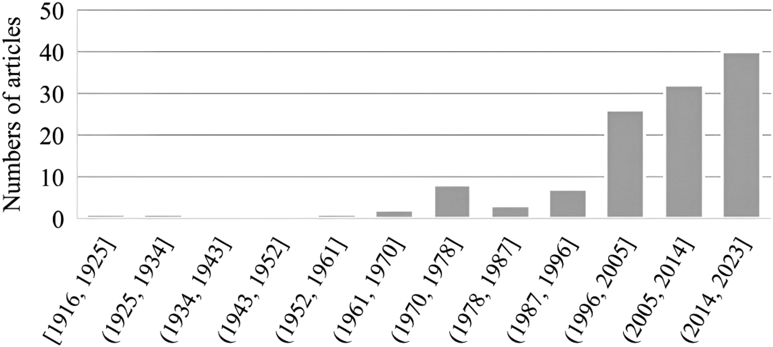
Reactive silencers
Helmholtz resonator
A Helmholtz resonator,37–40 whose history dates back to ancient Greece, usually consists of a cavity and one or more tubes connected to the outside (Figure 4(a)) and is a common structure for absorbing sound waves at a specific frequency, the resonant frequency. Helmholtz resonators have a high transmission loss in a narrow resonant band, but their sound absorption performance is poor in non-resonant regions. The Figure 4(b) shows the transmission loss of a simple Helmholtz resonator. Helmholtz resonators are used as sound absorbers in various industries, such as pipelines and valves,42–48 double walls,49–51 gas turbines,52–56 internal combustion engines,57–63 and centrifugal fans.64–68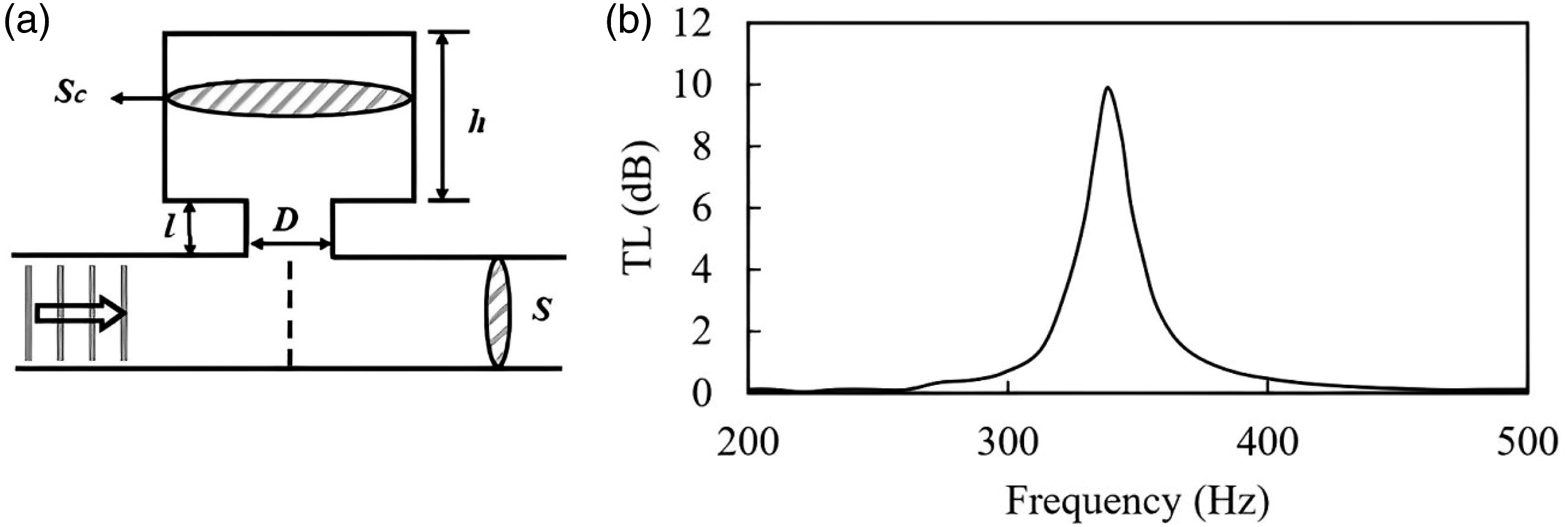
Both active and passive control can improve the performance of the Helmholtz resonator. Active control of the resonant frequency of a Helmholtz resonator is usually complex in structure and short in stability.58,67,69–72
In passive control, many studies have been conducted to increase the absorption performance and bandwidth and reduce the occupied space at low frequencies. Studies have shown that the geometry of the Helmholtz resonator affects its performance.73–76 For example, if you increase the volume of the cavity or the length of the Helmholtz resonator tube, its resonant frequency will decrease. 74 These changes require an increase in the dimensions of the Helmholtz resonator and a larger footprint. To improve the noise reduction performance of the Helmholtz resonator at low frequencies in a confined space, some ideas have been proposed such as a spiral or curved or helical neck that extends the neck as far as possible into the confined space to lower the resonant frequency.77–81
Studies have shown that multiple resonators tuned to different frequencies can be used to increase bandwidth at low frequencies. The study of different types of resonator arrangements has shown that the series and parallel arrangement of resonators generally results in better performance and wider bandwidth.82–84 Helmholtz resonators are generally used in conjunction with other sound absorbers and insulators and result in improved performance of these absorbers and insulators. As an example, we can mention the use of Helmholtz resonators alongside micro-perforated panels85–88 or various silencers.41,89
Expansion chamber
Since the birth of internal combustion engines, reactive silencers have been designed as exhaust silencers. Some valuable theoretical and experimental works have been done to optimize the design of reactive silencers.
90
Optimization and designing of the exhaust silencer are done based on the emitted sound level, determined by the net flux of energy in the exhaust trailing pipe of an internal combustion engine.
91
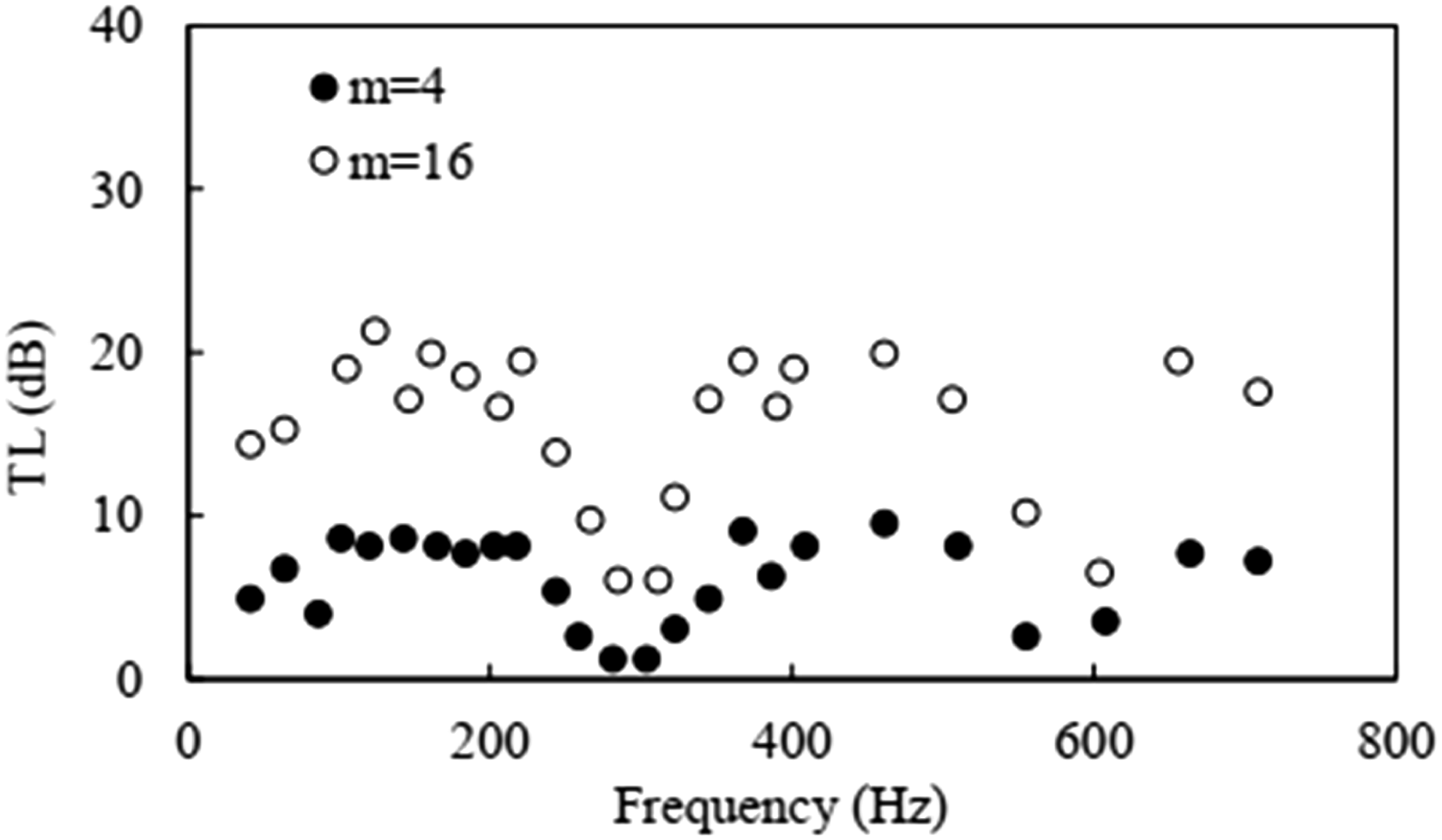
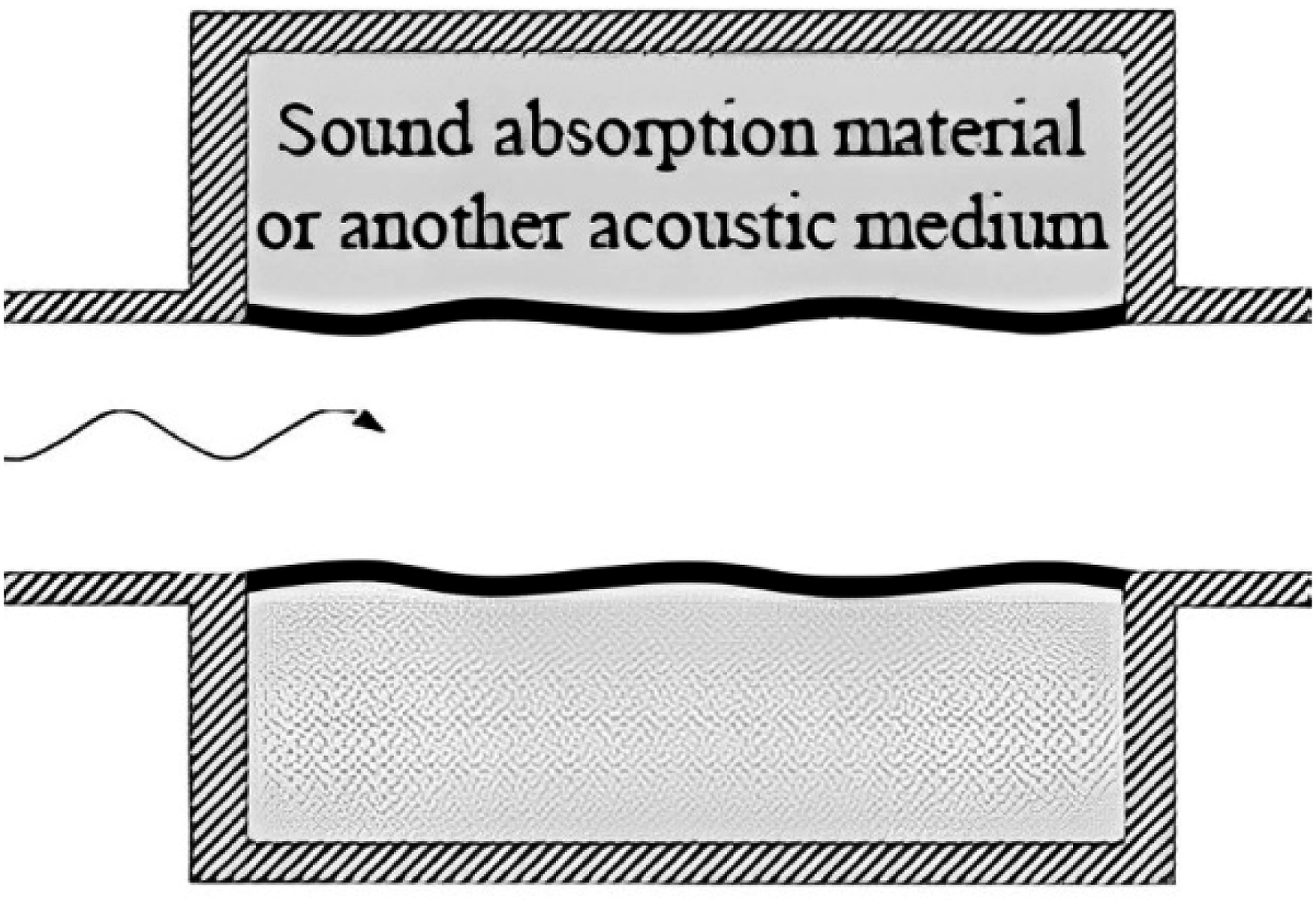
An expansion chamber, the simplest type of reactive silencer, is a simple chamber placed in the path of sound waves in a duct. It can reduce noise at low frequencies and is therefore used in the exhaust system of internal combustion engines. Its noise reduction results from the change in cross-section, the reflection of the sound waves because of the change in impedance, and the addition of the reflected waves to the subsequent destructive interference with the incoming sound. Figure 5 shows that the attenuation of low frequencies in an expansion chamber increases with the expansion ratio.92,93 The expansion ratio is the ratio of the cross-sectional area of the chamber to the cross-sectional area of the exhaust pipe. The shape of the expansion chamber was also studied and had no significant effect on the attenuation of low frequencies.
92
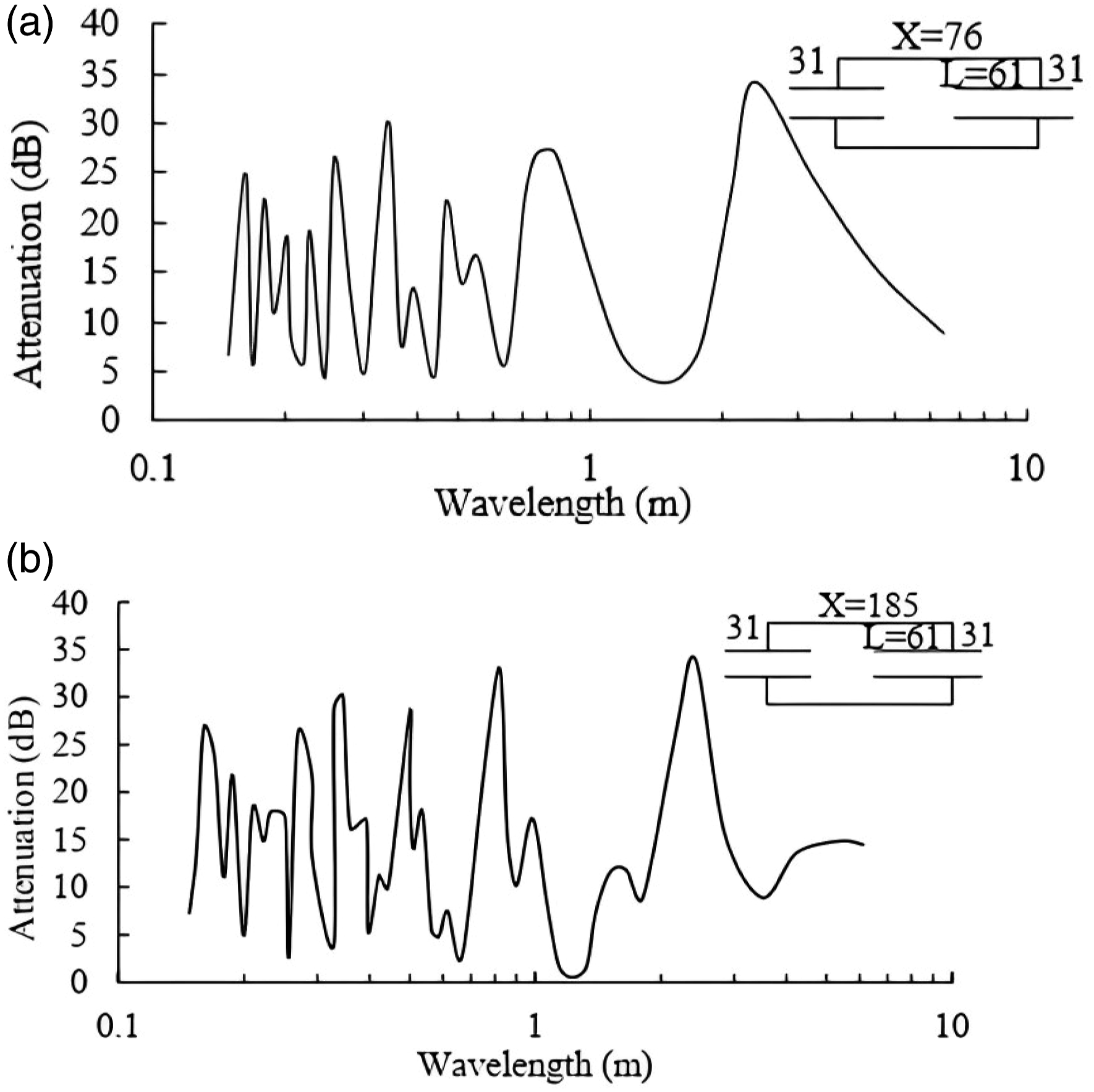
By testing on a variety of engines, it was shown that an expansion chamber comprising extensions (simple tubes protruding from the chamber) could significantly reduce exhaust noise. The studies of the performance of such silencers at low frequencies show that good low-frequency noise reduction can be achieved when the maximum attenuation wavelength of 4L is greater than the maximum amplification wavelength 2x, as shown in Figure 6. In Figure 6(a), good attenuation can be seen compared to Figure 6(b) at low frequencies. In Figure 6(a), the maximum attenuation occurs at a wavelength of 2.54 m. This is more than twice the length of the chamber and results from the length of the intrusion pipe of 0.61 m.
94
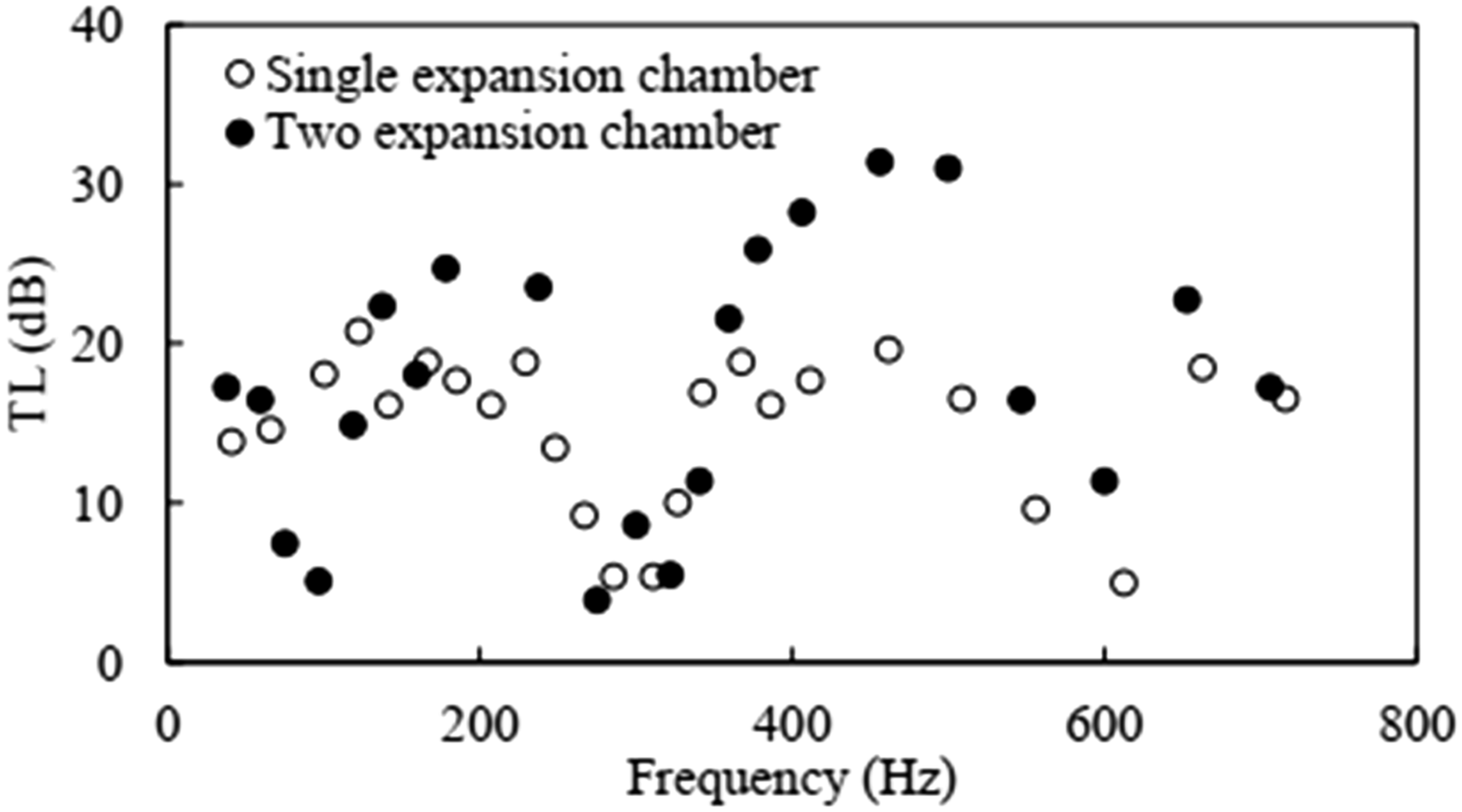
Besides a single expansion chamber, the noise reduction in multiple expansion chambers and sub-chambers has been investigated numerically, theoretically, and experimentally.92,95,96 Figure 7 compares the TL of a single chamber and a double chamber obtained from experimental results. With the increase in the number of chambers, the attenuation has increased at all frequencies except those around 100 Hz.
92
Using sub-chambers with extensions or partitions has been shown to shift the peak of TL to low frequencies, but reduce bandwidth.
97
Despite the advantages of expansion chambers, such as simple construction, low cost, and flexibility in use, the increase in chamber volume to achieve good low-frequency noise reduction and the increase in back pressure have led researchers to consider changes and modifications. For example, the use of flow guide annuluses at the inlet and outlet of the tubes or the use of a perforated tube between two neighboring coaxial tubes can significantly reduce the pressure drop of the silencer.
98
The attenuation versus frequency of expansion chamber with expansion ratio m = 4 and m = 16.
92
Effects of geometrical parameter variations on reactive exhaust silencer performance at low frequencies. Respective configurations (a), and (b) shown on inset drawings (dimensions in cm).
94
The attenuation versus frequency for one and two expansion chambers.
92
Drum-like silencer
Huang
99
is the first researcher who introduced and optimized a drum-like silencer. This silencer comprises two identical—tensioned—membranes, each membrane supported by a solid-walled cavity. When the membranes are removed, an expansion chamber remains (Figure 8). The membrane behaves like a drum skin. The incoming wave causes the membrane to vibrate, and simultaneously the sound radiation creates a reflected wave which in turn attenuates the transmitted wave. The idea for making a drum silencer comes from combining a micro-perforated plate with a backed cavity, one of the most successful low-frequency sound absorption techniques investigated by Maa.
100
The performance of the drum silencer was compared with that of a fibrous duct lining with two cavities. The fibrous duct lining is a standard method for sound and thermal insulation of ducts, but it only works well at medium and high frequencies. The results show that the optimal cavity shape of duct lining is much deeper than that of a drum silencer.
100
This means that the size of the drum silencer is smaller and, therefore takes up less space. In addition, the performance of the drum silencer improves more at low frequencies compared to the duct lining as the total volume of the cavity increases. The studies also show that filling the cavities with absorbent materials improves performance only at medium and high frequencies and has the opposite effect at low frequencies.
101
It was shown that parameters such as mass and membrane tension affect the performance of the silencer and change its stop-band frequencies.102,103 According to these studies, a heavy metal membrane with a medium tension level is the best choice to reduce low-frequency noise. Filling the shallow cavities with helium gas improves the performance of the drum-like silencer at low frequencies by increasing the bandwidth.
103
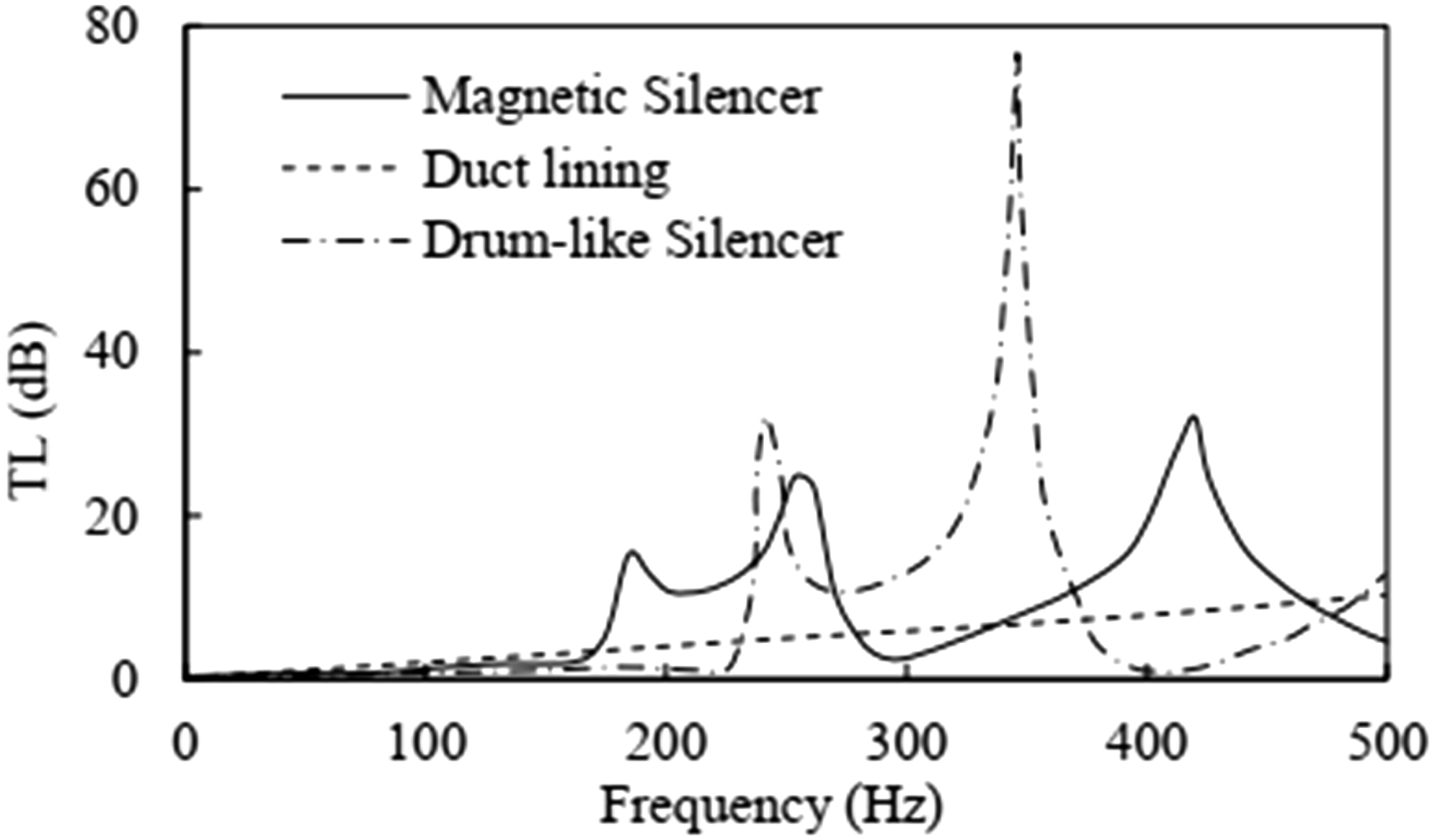
Numerical and experimental studies have been conducted to show that the magnetic force can improve the performance of the drum-like silencer at low frequencies. The comparison amongst the performance of the magnetic drum-like silencer, the simple drum-like silencer, and the duct lining in Figure 9 shows that the performance of the silencer at low frequencies can be improved by adding a magnet and adjusting the cavity pressure. This improvement only applies to frequencies above 170 Hz and, for frequencies below that, there is no change.
104
Another advantage of the drum-like silencer is that it reduces the instabilities of a thermoacoustic system by reducing its resonant frequency and increasing the phase difference between unstable heat release and pressure fluctuation. This is done by changing some properties of the drum-like silencer, such as the membrane tension, the length of the silencer, and the depth of the cavity.
105
Thermoacoustic instabilities occur in combustion systems such as rocket engines, gas turbines, and premixed pre-vaporized civil airplane engines when unstable heat release oscillations are accompanied by acoustic oscillations. However, there are some important issues regarding the actual use of drum silencers. These include the reduction of the tensile force on the membrane over time, especially when exposed to turbulent flow, and the resulting change in the TL spectrum, as well as the possibility of self-induced vibration and membrane failure at high-speed sites such as wind tunnels.
101
An experimental study of the effect of flow on drum-like silencers has been carried out, showing that there is no flow-induced flexural instability at the usual velocities of ventilation systems when high tension is applied to the membrane. In addition, the effect of flow turbulence was studied in a wind tunnel with a flow velocity of 9 m/s and 6% turbulence. It has been shown that the noise caused by the turbulence is negligible under these conditions when high tension is applied to the membrane.
106
Two-dimensional schematic of a drum-like silencer.
99
Optimal TL spectra for the drum-like silencer (long dash-dot), duct lining by filing two cavities by glass fiber (dash line), and magnetic silencer (solid line).
104
Flute-like silencer
Huang
16
has also introduced a broadband noise reflection mechanism called a flute-like silencer, whose sound reflection performance is suitable and even higher compared to the drum-like silencer, and which requires less tensile stress compared to the drum-like silencer. Figure 10(a) shows the geometry of this silencer, which contains laterally branched cavities filled with a light gas such as helium. The cavities are covered with impermeable and elastic membranes as two holes, one at the entrance and the other at the exit.16,108 The incident waves are scattered both at the central channel and at the bypass of the cavity. The higher speed of sound in the bypass leads to the resonance and consequently to a peak in the spectrum of TL. When the incident sound frequency coincides with the vibroacoustic frequency, another resonance occurs, leading to resonance and another change in the spectrum of TL (Figure 10(b)). The TL of three silencers with the same geometry is shown in Figure 10(b). These silencers are flute-like, drum-like, and drum-like with a helium-filled cavity (DSH), and duct lining. From Figure 10(b), it can be seen that the spectrum of TL for the DSH tends toward lower frequencies but has a narrower bandwidth than the flute-like silencer. Another advantage of the flute-like silencer over the drum-like silencer and the DSH is that less tensile force is required in the membrane, making it easier to use under practical conditions. In particular, in situations such as large ducts or long membranes that require high tension, the flute-like silencer is more beneficial.
107
The bandwidth of the TL spectrum can be increased by adding a third membrane to the flute-like silencer (Figure 10(c)). Here, the tension on membranes 1 and 2 will be removed and only membrane 3 will be tensioned, therefore, the tension force required on membrane 3 will be greater than the tension force on membranes 1 and 2.
107
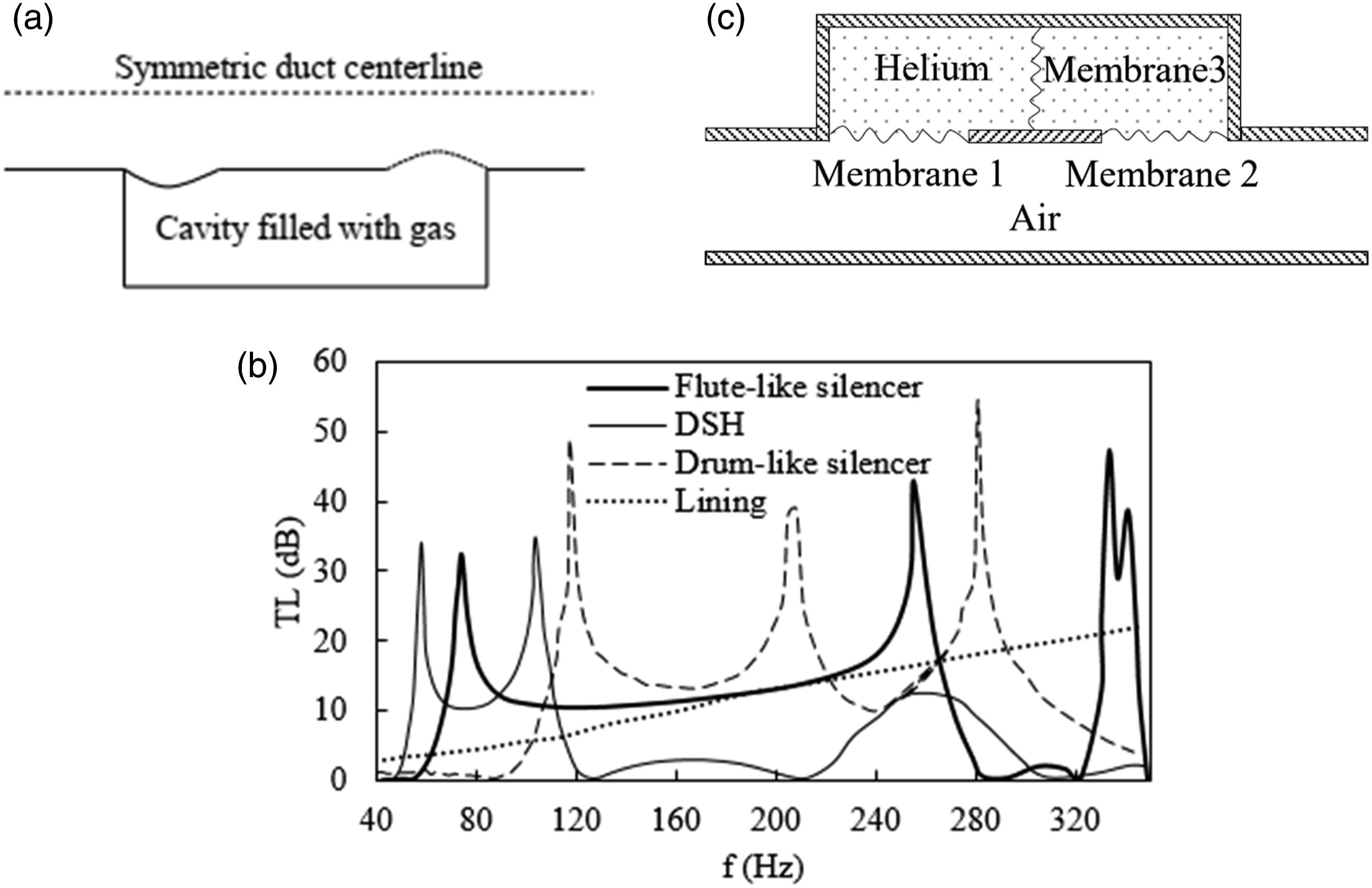
Plate silencer
The design of the plate silencer has recently been focused on attenuating low-frequency noise. A plate silencer is similar in design to a simple drum-like silencer, except the cavities are covered with a plate instead of a membrane. Therefore, owing to the smooth surface, these silencers are characterized by low flow resistance and are resistant to cold, heat, and pollution.
109
The physical geometry of a plate silencer is like the geometry shown in Figure 8.
110
This silencer comprises two plates secured to the top and bottom walls of the duct, with an air-filled chamber existing behind each plate. The pressure of the sound waves entering the silencer causes the plates to vibrate due to the difference in sound pressure on their sides. This vibration creates a sound field in each air cavity. Part of the sound energy generated returns to the inlet and causes transmission loss.
111
Huang
112
first presented the plate silencer’s initial design; then others tried to optimize it. Studies show that the density and bending stiffness of the plate affect the performance of the silencer.
113
The most favorable performance is obtained with a high stiffness and a low plate density, resulting in a low resonant frequency. A study was carried out to produce a lightweight composite plate with high bending stiffness, enabling a silencer with more compact dimensions and better performance. This plate had a stop band ranging from 229 to 618 Hz and a total TL beyond 10 dB.
114
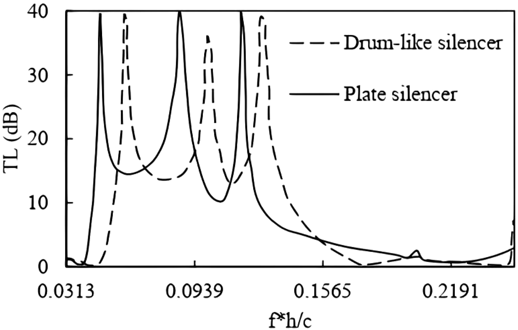
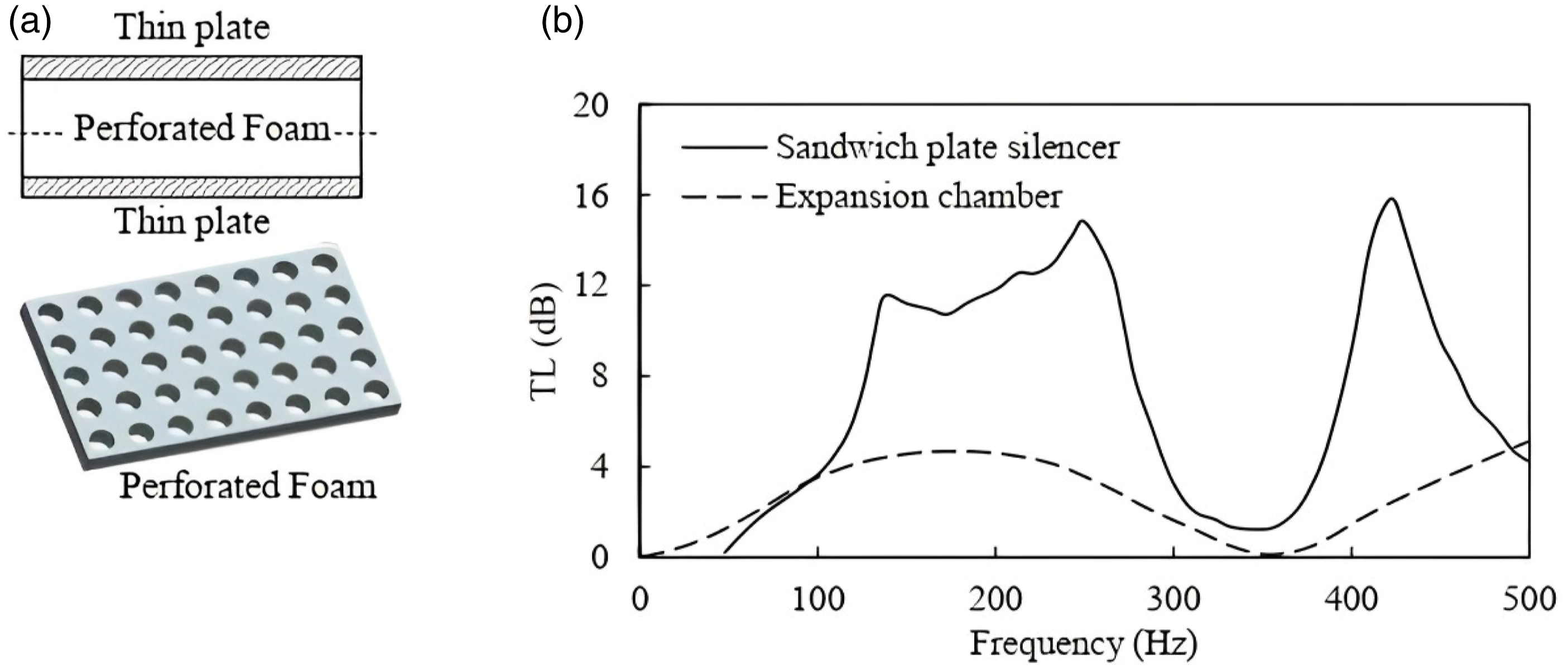
Figure 11 compares the TL of a clamped plate silencer with a drum-like silencer with the same mass ratio and cavity geometry. The plate silencer has a remarkable performance and a wider bandwidth at lower frequencies compared to the drum-like silencer. Compared to simple support, the boundary condition of the clamped end used here is more practical.111,115 Figure 12(a) and (b) demonstrates a plate silencer with sandwich plates, each plate comprising two thin aluminum sheets and a perforated foam core of Rohacell IG-31, and the TL of the silencer compared with that of an expansion chamber with the same geometry, respectively. The new plate silencer performs well at low frequencies.
110
Comparison of TL of drum-like silencer with plate silencer versus frequency f, duct height h, and free space sound speed c. (a) Schematic representation of the sandwich construction, (b) comparison of TL of sandwich plate silencer and expansion chamber.
110
Perforated reactive silencer
Figure 13
116
shows a simple geometry of a reactive perforated silencer. This silencer comprises a combination of a simple expansion chamber and a perforated tube connecting the entrance of the chamber to the exit. The gases pass through the perforated tube, which are usually lined with sound-absorbing materials. As the gases pass through the perforations, high-frequency noise is absorbed by the sound-absorbing material, which converts it into heat energy. At the same time, low-frequency noise is reflected back towards an expansion chamber. This expansion chamber cancels out some of the low-frequency noise through a destructive interference process, resulting in an overall reduction in exhaust noise. (a) A picture of the perforated reactive silencer, (b) The transmission loss of a perforated reactive silencer (porosity 8.4% and dh = 0.498 cm).
116
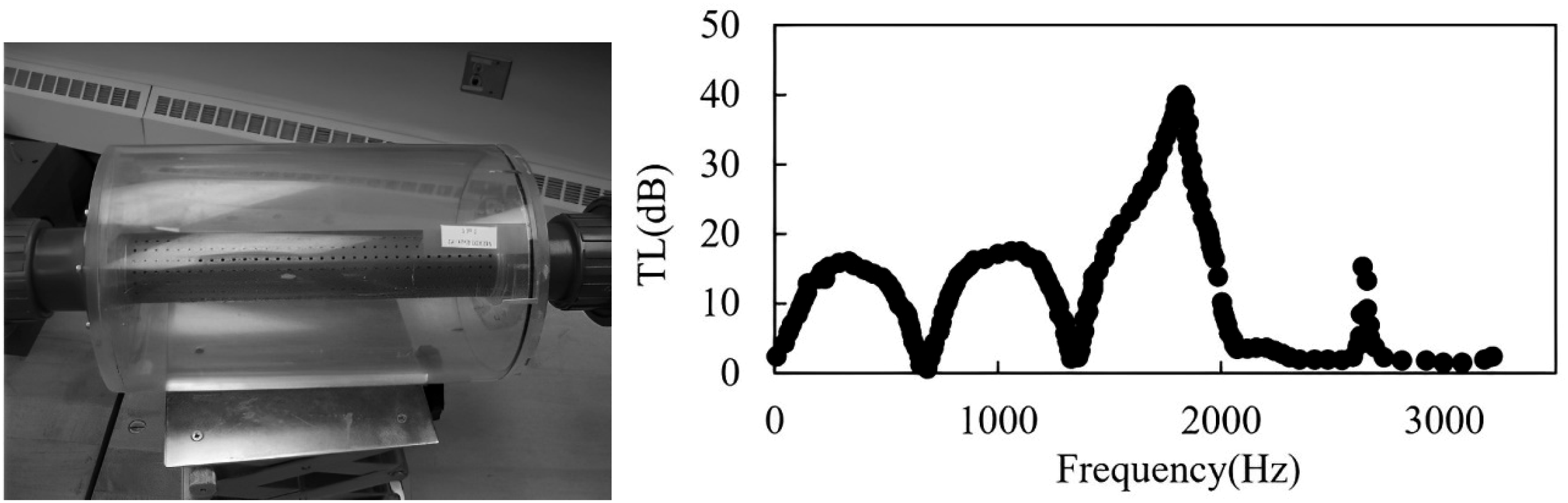
The experimental results show that the TL of this silencer is equal to that of the expansion chamber at low frequencies, and the TL is higher than that of the expansion chamber only at some high frequencies. Studies have also shown that the diameter of holes, porosity, and the addition of absorbent material around the perforated tube (dissipative perforated silencer) do not have a significant effect on the TL at low frequencies (below 200 Hz).116,117 However, there are many studies on these silencers and how to improve their performance. Since this article focuses on the performance of the passive silencers at low frequencies, it will be limited to them here.
Other low-frequency attenuator
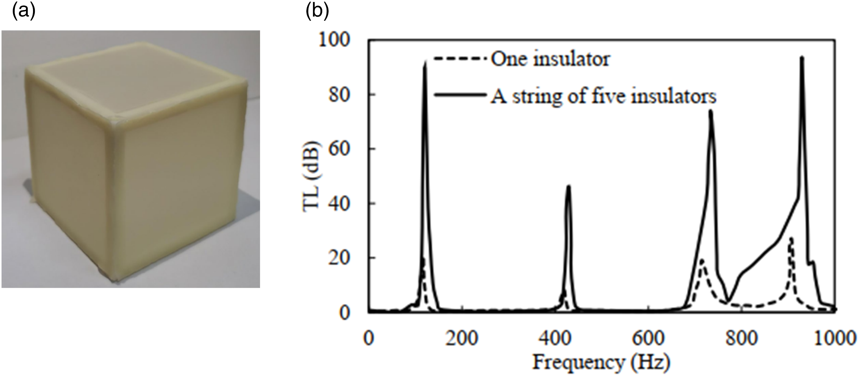
Membranes are often used in resonance-based silencers because their resonant frequency can be reduced by simply making them less elastic. This way, low-frequency noise can be reduced with a lightweight and small-volume silencer.118,119 The membrane-faced cubic box shown in Figure 14(a) is another case of a resonance-based insulator. It is a low-frequency multi-band insulator that has a significant TL of 21 dB at several low frequencies from 200 to 800 Hz. This insulation can be used as a string of multiples in a ventilation duct or pipe. Another advantage of the insulation is that it does not block the duct because its cross-section is smaller than that of the duct. Figure 14(b) shows the TL of one and a string of five insulators at different frequencies.
120
As seen in Figure 14(b), the TL value at frequencies below 500 Hz is significant only at two curve peaks and insignificant otherwise. (a) A photo of the membrane-based cubic sound insulator, (b) a comparison of TL of one insulator and a string of five insulators.
120
Hybrid silencers
In addition to reactive silencers, hybrid silencers have been developed to improve noise attenuation at low frequencies. Vent silencers are a common variety of hybrid silencers, comprising a diffuser at the input and a dissipative silencer (e.g., a parallel baffle or round rod baffle) at the output. The diffuser, a perforated tube, plays the role of a dispersive silencer and helps to reduce low-frequency noise. The mid and high frequencies are usually reduced by a dissipative silencer at the outlet.121–123 Vent silencers are used where steam or gas is vented into the atmosphere, and usually, the required attenuation in these locations is significant. As a result, the combination of diffuser pipe and baffles is heavy and occupies a large volume.
The combination of expansion chambers with dissipative silencers is another example of hybrid silencers. Figure 15(a)
124
shows the combination of two dissipative perforated silencers with one expansion chamber. The experimental results show an improvement in the performance of the hybrid silencer compared to an expansion chamber at low frequencies, especially on both sides of the resonance frequency (Figure 15(b)).
124
Reducing the length of the connecting tubes between the dissipative silencers and the expansion chamber is an influential factor in changing TL behavior at low frequencies.92,124 A similar result was observed with a hybrid silencer, which is a combination of a dissipative silencer and a Helmholtz resonator (Figure 15(c)).
116
Although the value of TL is significant at frequencies below 200 Hz in this silencer, another parameter that is important because of the structure of the silencer and the expansion chamber in such silencers is the flow pressure drop, which should be checked.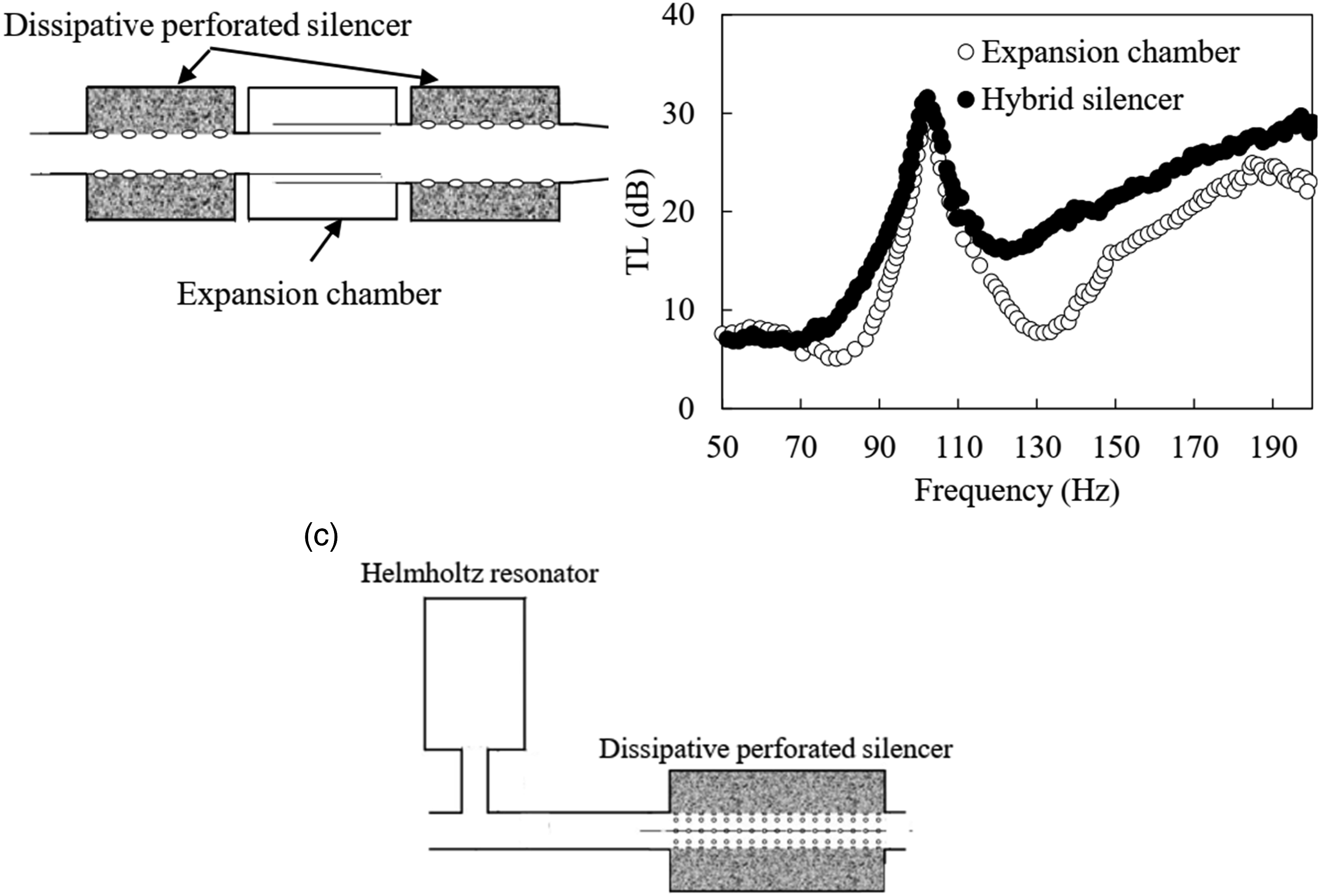
However, hybrid silencers are not limited to this. Williams et al.
125
introduced a new silencer comprising hybrid baffles that can replace parallel baffle silencers. As shown in Figure 16(a), the hybrid silencers consist of reactive and dissipative elements. Since the low-frequency noise is mainly attenuated by the reactive element and the mid-to high-frequency noise is mainly attenuated by the dissipative element, the length of the dissipative element is shorter than that of the equivalent simple dissipative silencer. The insertion loss of a silencer with hybrid baffles (Type *) is compared with the insertion loss of a dissipative silencer (without reactive element) in Figure 16(b). For the silencer with hybrid baffles, an average increase of 4.2 dB is observed at frequencies below 128 Hz and an 8.8 dB increase at the target frequency of 125 Hz. Similar observations were obtained for silencers with the type** and type*** baffles. The application in large ducts, easier to manufacture, installation, and maintenance are the advantages of this silencer compared to other hybrid silencers. However, the flow pressure drop in this design should be checked similarly to the previous designs because of the presence of the resonance chamber.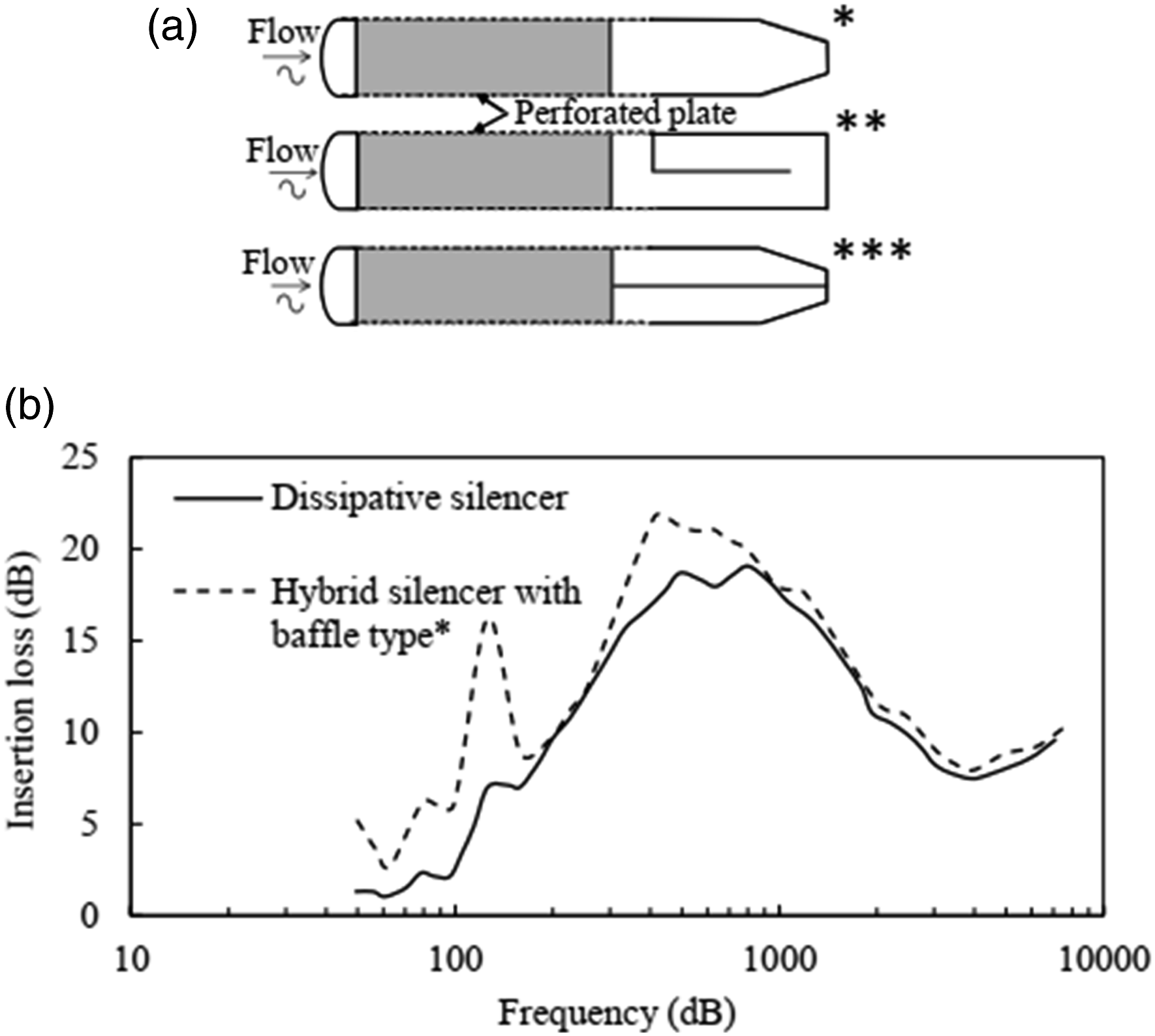
Conclusion
This article is a review of 126 journal and conference articles dealing with the topic of low-frequency noise reduction in passive silencers. Among passive silencers, reactive silencers have higher noise reduction at low frequencies. Helmholtz resonators with their simple structure are very effective in reducing noise at low frequencies, but their main problem is their very narrow frequency band. To solve this problem, some solutions have been proposed, including the use of series and parallel structures of several resonators with different resonant frequencies, which can significantly increase the bandwidth. The expansion chamber, a very simple example of a reactive silencer, was originally developed with the goal of reducing low-frequency noise in the exhaust of internal combustion engines. Geometric modifications to this type of silencer, such as increasing the expansion ratio or adding extensions, partitions, or combining multiple chambers, can improve the performance of this type of silencer at low frequencies. On the other hand, geometric changes can alter not only the peak attenuation value but also the bandwidth of low frequencies. However, since noise reduction in expansion chambers depends on the expansion ratio and cavity volume, problems such as lack of space and increased pressure drop make the use of such silencers limited or even impossible in large industrial applications such as wind tunnels and test facilities.
The use of two identical membranes with moderate tension on the expansion chamber cavity can provide better performance with a smaller space requirement than the expansion chamber. In this type of silencer, which is called a drum-like silencer, the frequency bands can be changed by changing the mass and tension of the membrane, depending on the design conditions. It is also possible to reduce the thermoacoustic instabilities of combustion systems by changing the resonant frequency, which depends on the tension of the membrane, the length of the silencer, and the depth of the cavities. The addition of helium gas or magnets in the cavities improves the performance of the silencer at low frequencies. The reduction of the tension of the membrane over time or at high velocities and in turbulent flow is one of the practical problems of this silencer, especially in large dimensions. The problem was solved in the flute-like silencer by reducing the length of the membrane. Compared to expansion chamber and drum-like silencers, this silencer has better performance at low frequencies. The addition of helium gas to the cavities of this silencer shifts the peak of the TL spectrum to lower frequencies, but significantly reduces the bandwidth.
Plate silencers with lightweight and high-stiffness plates are a suitable option for reducing low-frequency noise and low-pressure drop, especially in ventilation ducts, and the use of sandwich plates improves their performance. However, the practical use of this silencer in large ducts should be examined. In such a situation, where the length of the plate increases, the connection of the plate with the walls and the vibration of the plate should be checked.
Among hybrid silencers, which consist of the combination of two or more reactive or dissipative silencers, some silencers are practically used in industry today, including vent silencers, which are a combination of a diffuser and a dissipative silencer or a combination of a diffuser, a dissipative perforated silencer and a dissipative silencer. These silencers are versatile but bulky. The second category of hybrid silencers are silencers that consist of a combination of one or more expansion chambers or Helmholtz resonators with one or more dissipative perforated silencers. These silencers have good performance at low frequencies compared to reactive silencers, but due to their structure and the existence of the reactive part, the pressure drop in them should be calculated and considered as a fundamental factor in the design, especially when the dimensions of the silencer become larger. The third category is silencers with combined baffles in which a baffle consists of two dissipative and reactive parts. Because of the presence of the dissipative part, these silencers have a high ability to reduce noise at high frequencies, and because of the reactive part, they can reduce noise at low frequencies. Therefore it seems that such silencers can be widely used in industries that need to reduce noise in a wide frequency range.
Footnotes
Declaration of conflicting interests
The author(s) declared no potential conflicts of interest with respect to the research, authorship, and/or publication of this article.
Funding
The author(s) received no financial support for the research, authorship, and/or publication of this article.