
Abstract
In this paper, a semi-active nonlinear artificial intelligence compound controller for marine engines was developed to improve vibration reduction characteristics across a wide frequency range. A mathematical model was developed and investigated for two-stage vibration isolation systems (Virgin IslandsS) considering vertical, roll, and pitch motion. The passive mathematical model of the magnetorheological damper was also developed and integrated with the two-stage VIS. The passive numerical analysis was validated through the experimental investigation. Force transmitted from the engine to the base was evaluated on the validated model using four different strategies, that is, conventional passive, semi-active low, semi-active high, and semi-active controlled damper. In a semi-active–controlled damper, a mathematical model is developed for controlling the force by developing a nonlinear artificial intelligent compound controller (NAICC) using the algorithm of chaotic fruit fly and fuzzy logic control. The results show that the application of NAICC has a better isolating effect than the passive VIS over a broad spectrum of frequencies. By strengthening the control effect in the low-frequency resonance zone, marine engine vibration reduction performance was significantly enhanced.
Introduction
Safety and reliability are the primary considerations in the design and development of a ship. 1 Marine engines are the core of overall design and operation and play a vital role as the ship’s heart. Vibration generated by the marine engine, propellers, gearboxes, propulsion shafts, and auxiliary machinery are the five main groups of radiated vibration sources in ships. Structure-borne noise is caused by vibrations propagating through the structure. 2 To reduce vibration transmission, passive vibration isolators are often used to suspend several vibration sources. The effectiveness of passive isolators depends on their ability to reduce low-frequency vibrations while ensuring that the machinery is appropriately aligned.
The damping requirements vary at different levels of high and low frequencies. Low damping is often essential for high-frequency isolation, while high damping is essential for low-frequency isolation. During navigation, ships are typically affected by wind, waves, and various exciting forces, resulting in vibration occurring in the loading direction. As a result, associated vibration can be triggered in many directions simultaneously. Transverse, longitudinal, torsional vibration, and coupled vibration, that is, torsional-longitudinal, torsional-transverse, and torsional-transverse, are examples of common coupled vibration forms of propulsion shafting. Deformations and rotational angles are formed when associated vibration occurs.3–5
However, the pulsing of cycle work in the main marine engine and the non-uniformity of the propeller working area might result in an exceedingly complicated exciting force. These external and internal incentives interact and directly impact the dependability of marine engines, posing a significant concern to ship safety. Today, mainly used passive dampers have limits and can no longer solve new problems. A semi-active (SA) or active system can minimize vibration. 6 Actuators complement springs and dampers in the active system. The actuator can precisely create the force required to dampen the sprung mass. The significant disadvantage of active systems is the relative complexity, high cost, energy consumption, and difficulties in implementing a fail-safe system. Hence, a vibration isolator can be investigated to reduce the vibration to reach the marine engine.
Vibration isolation uses an isolator between a platform and a base to limit vibration transmission among them. The force exerted by the isolator on the platform is commonly referred to as the control force. Three approaches are available depending on how the force was generated, that is, passive, SA and active vibration isolation.7–9 The consideration of more advanced approaches, such as semi-active or active techniques, has been driven by unpredictable factors that may not have been taken into account during the design process, changes in working circumstances, and the aim to increase low-frequency performance. By allowing the isolator’s dynamic properties (stiffness and damping) to be changed in real-time, semi-active VIS enables some degree of flexibility to change circumstances. Active isolators have several advantages, including the capacity to shift position, give zero static deflection, and implement adaptive control approaches.10,11 As a result, active VIS is ideal for a wide range of applications. Active vibration isolation presents specific extra difficulties that must be overcome, including signal processing in real-time, dynamics isolator, control system instability, and control force impact on the structural support. When the isolator’s impact on the base structure response is negligible, it is frequently assumed in many applications where the base structure does not interact with the isolator. There are additional applications, such as certain maritime ones, where the isolation problem must consider the displacement of a flexible base structure as one of its components.
Recently, semi-active vibration isolation, as a compromise between passive and active vibration isolation, has become a research hotspot for domestic and foreign researchers.12,13 In comparison to a passive vibration isolation system, a semi-active vibration isolation system has better vibration isolation performance, especially in a low-frequency range. Compared with an active vibration isolation system, a semi-active vibration isolation system does not require a lot of energy and weight. 14 Secondary vibration sources (MR dampers) produce control forces to stop the primary vibration transmission. The passive resilient isolators are frequently arranged in series or parallel with them. An SVIS is the composite of the MR dampers, sensors, and controller. The semi-active damper can change the damping characteristic based on data from various sensors. The fail-safe system of the MR damper can be secured with a permanent magnet. Various authors verified the performance of semi-active control of MR dampers. But they do not deal with the influence of the MR damper dynamic behaviors with respect to response time and range. 15 The algorithms like, Skyhook, Skyhook linear, acceleration-driven damper, Mixed Skyhook and ADD, Mix-1-sensor and Power-Driven Damper algorithms can increase comfort. Semi-active damping is usually developed in purely virtual simulation or simplified physical models. The advantages of a virtual simulation are short computing time, price, and an easily editable dynamic model.
Several control applications for suspension systems have used LQ Controllers, Genetic Algorithms, Fuzzy Logic Controllers, and PID tuning to improve vehicle stability. PID controllers are commonly used in industry because they rely solely on the evaluated variables of a dynamical system.16,17 On the other hand, fuzzy controllers provide a flexible method to account for the impact of the interaction of the various system inputs by applying rule sets based on the occurrences of different events in the system. Given the benefits of PID and rule-based controllers, two ways have been developed for implementing Fuzzy-PID hybrids in a suspension system: (1) Utilizing fuzzy controllers to tune the PID parameters or (2) using the control techniques separately in the system to provide better vibration reduction. Jinzhi et al. 18 developed a control technique for suspension systems that combined a GA-based PID tuning with a fuzzy controller, with the PID minimizing vertical body acceleration and the fuzzy controller minimizing pitch acceleration. Jianwei et al. 19 devised a switching control technique for use in a SASS using a PID and a fuzzy system. The Fuzzy-PID control approach provided robust performance and minimized vertical acceleration compared to the individual Fuzzy control systems. Therefore, in this paper, a semi-active nonlinear artificial intelligence compound controller for marine engines was developed to improve vibration reduction characteristics across a wide frequency range. A mathematical model was developed and investigated for two-stage VIS considering vertical, roll, and pitch motion. The passive mathematical model of the magnetorheological damper was also developed and integrated with the two-stage VIS. The passive numerical analysis was validated through the experimental investigation. Force transmitted from the engine to the base was evaluated on the validated model using four different strategies, that is, conventional passive, semi-active low, high, and controlled damper. In a semi-active–controlled damper, a mathematical model is developed for controlling the force of NAICC.
Mathematical modeling of two-stage semi-active vibration isolation system
Mathematical modeling of the vibration isolation system
The mathematical model is developed by considering the pitch, roll, and vertical motion around the engine’s output shaft. The mass of the engine and intermediate mass are me and mm. The Ix and Iy are the MOI around the X and Y axes. Figure 1 depicts a two-stage vibration isolation system with coordinate axes. Compared to a single-stage vibration isolator, the intermediate masses provide more DOFs to the system and improve the frequency characteristics. In general, the initial natural frequencies are above tens of Hertz for the intermediate mass and engine implying that they are rigid bodies with six DoF. (a) Two-stage vibration isolation system; (b) coordinate axes located at the CoG of the supported mass; (c) principal elastic axes associated with isolator i located at the point of action of the isolator on the supported mass; (d) principal elastic axes and local coordinate axes associated with isolator i (rotations are not shown for clarity).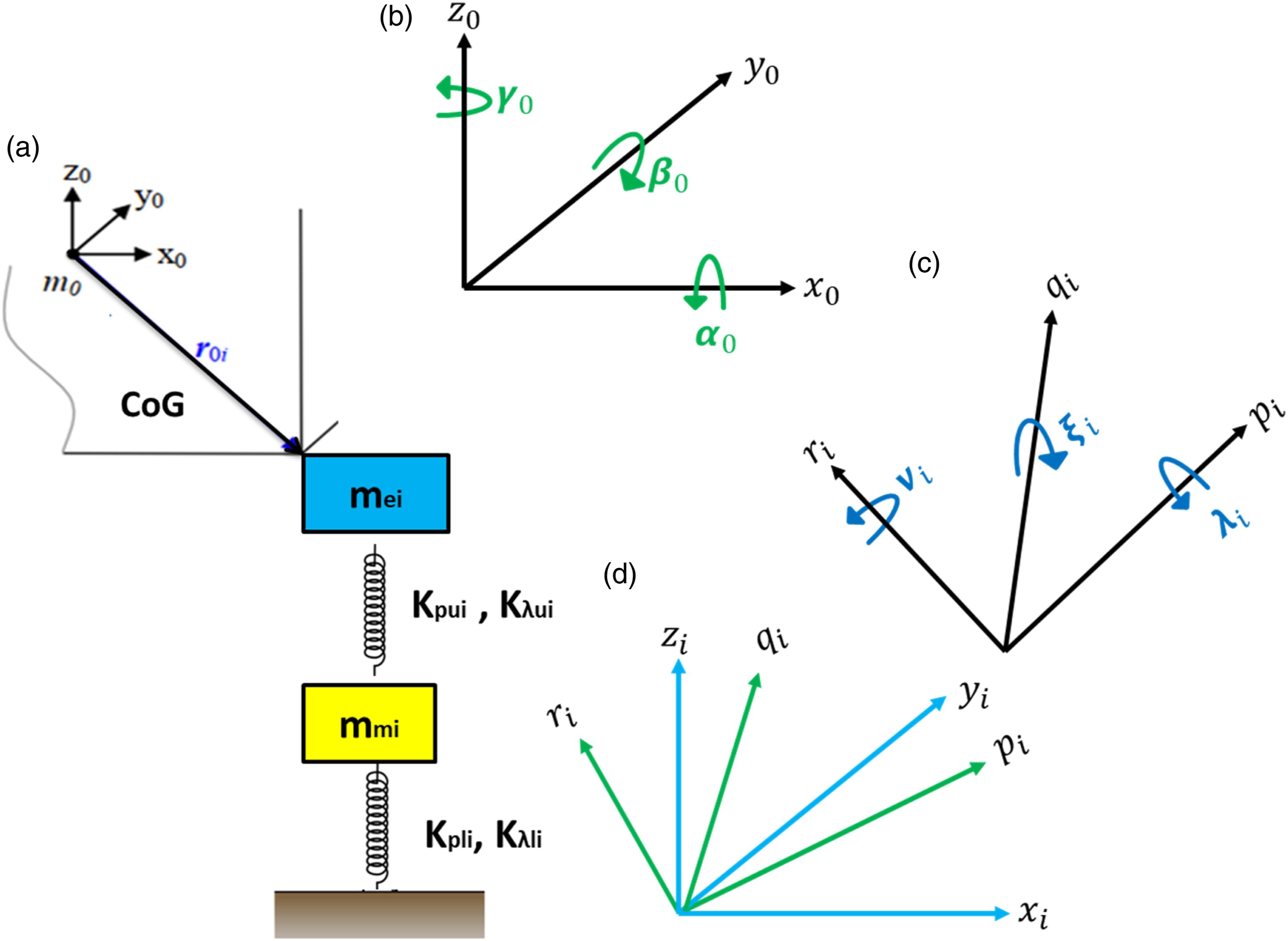
The primary purpose of semi-active control for the two-stage VIS with horizontal configuration is to suppress the engine’s vertical and coupled vibration mode in three dimensions. Matrix approaches may be used to generate the equations of motion of a general two-stage VIS.
20
Figure 1 depicts a mass m0 supported by a two-stage vibration isolator at a position r0i = {r0x, r0y, r0z}
i
T concerning a coordinate system at the supported mass CoG.21–23 The intermediate mass separates two collinear springs in the two-stage isolator. The upper spring has translational Kpui and rotational stiffness Kλui, and u for l represents the subscript of the spring’s lower stiffness. The intermediate masses are of mass mi and have inertial properties Ipi. The intermediate mass’s height might be reduced to reduce coupling among lateral forces and rotating displacements, and vice versa. Equations (1)–(5) describe the motion of the intermediate mass (


Forces exerted to supported mass
The forces exerted by a single isolator to the supported mass are given in equations (6) and (7)


Moments exerted to supported mass
Moments (

Adding the moments concerning the supported mass’s CoG


Further manipulation yields


is the rotational-translational stiffness
Forces exerted to the intermediate mass
The forces exerted to the intermediate mass are given by

Therefore


Moments exerted to the intermediate mass
The moments exerted to the intermediate mass are given by

Therefore

Matrix equations of an isolator
Equations (7), (17), (20), and (24) can be assembled into a matrix equation with stiffness matrix elements given by equations (21)–(24)


Excitation characteristics of the engine
For the two-stage semi-active VIS to be vibration controlled, simulation analysis of the vibration source is essential. In the low-frequency band, torque variations around the crankshaft (x-axis) are the main source of excitation, while reciprocating inertia forces in the vertical (Y-axis) direction are the main sources of excitation in the high-frequency band. Multi-ignition sequences are used to generate the exciting force for the entire cylinder block. Equation (26) gives the vertical second-order inertial force, and equations (27) and (28) give the longitudinal and pitch moment around the engine.
20


Design and control of magneto rheological damper
Mathematical model of MR damper
In the last decade, researchers have developed different models to predict the behavior of MR dampers. The models like Bingham, viscoelastic-plastic, and BoucWen models were found to have the most realistic features. The modified Dahl model is used in this study to characterize MR damper behavior. This model has a distinct advantage by taking into account the force-velocity relationship at low velocities (Figure 2). Equations (29)–(32) contain the equations for the MR model, and equation (29) gives the damper force F. Modified Dahl model for MR damper.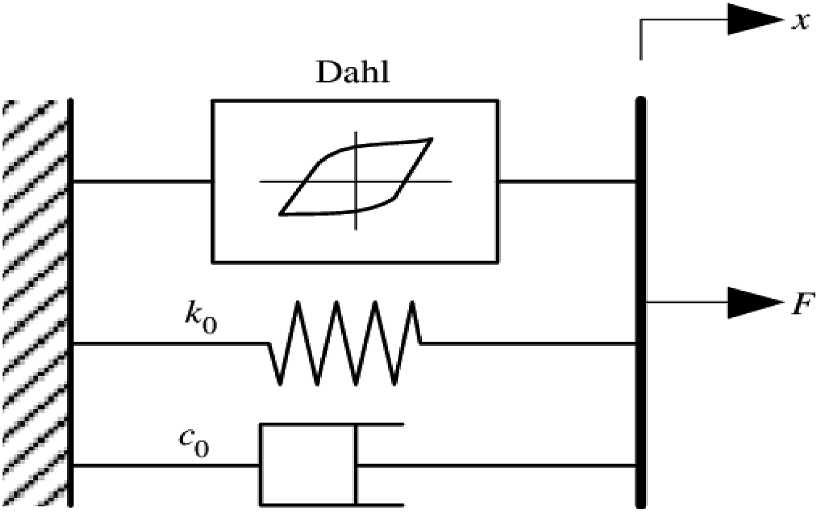

In equation (29), damping coefficient (C0) and stiffness coefficient (K0) are given with x as a displacement. Fd is the Coulomb force, and f0 is the damper force. Equation (30) expresses Z as a non-dimensional hysteretic variable

σ describes the hysteretic loop form. Experiment results show a relationship among C
0
and F
d
and exerted voltage, which is stated as

MR dampers have a damping coefficient of C
0s
and a Coulomb force of F
d
at zero voltage, respectively. The parameter u represents the function of the voltage applied to the parameters

Z denotes the MR damper’s response time. Higher Z results in a faster response time. Voltage is exerted as V. More information may be found in Zhou et al. 24
Strategies for a marine engine system’s semi-active isolation system
Large vibrations are generated as lateral, vertical, and bounce motions are coupled in different degrees of motion. As a consequence of this, there are four distinct categories of secondary isolation systems that are taken into consideration. 25 These categories are as follows: (a) passive with conventional dampers, (b) SA-low (Sa-L at 0.25 A), (c) SA-high (Sa-H at 0.5 A), and (d) SA controlled (Sa-C) including fuzzy logic and CFFC. 26
Controls for semi-active isolation systems
Figure 3 illustrates the control mechanism for the semi-active isolation system concepts. The system controller uses the present state of the engine to generate fuzzy logic control. This control is then used by the system. There is a disparity between the amount of damping force that is readily accessible and the quantity of damping force that is specified by the damper controller. In continuous operation, the damper controller reduces uncertainty by using the available damping force. MR dampers replace secondary vertical passive dampers. To commence, a simulation of the passive system is run with the secondary vertical passive damper forces set to zero. After that, a simulation of the MR damper control model is run with no secondary vertical passive damper forces. Control scheme of semi-active isolation system strategies with Fuzzy logic controller and chaotic fruit fly controller.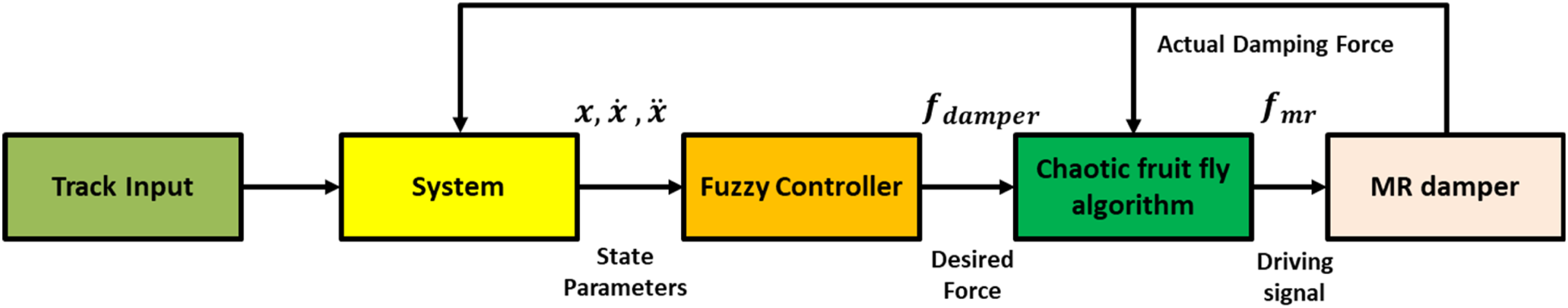
Fuzzy controller
The fuzzy logic controller governs the damping force necessary to reduce instabilities by assessing the status of the engine. It is utilized in conjunction with a skyhook control method in which a fictitious damper is connected between the engine mass and the fictitious sky. It operates on an “on-off” basis. The Skyhook control algorithm is denoted by equation (33) Logic control scheme used in the fuzzy algorithm.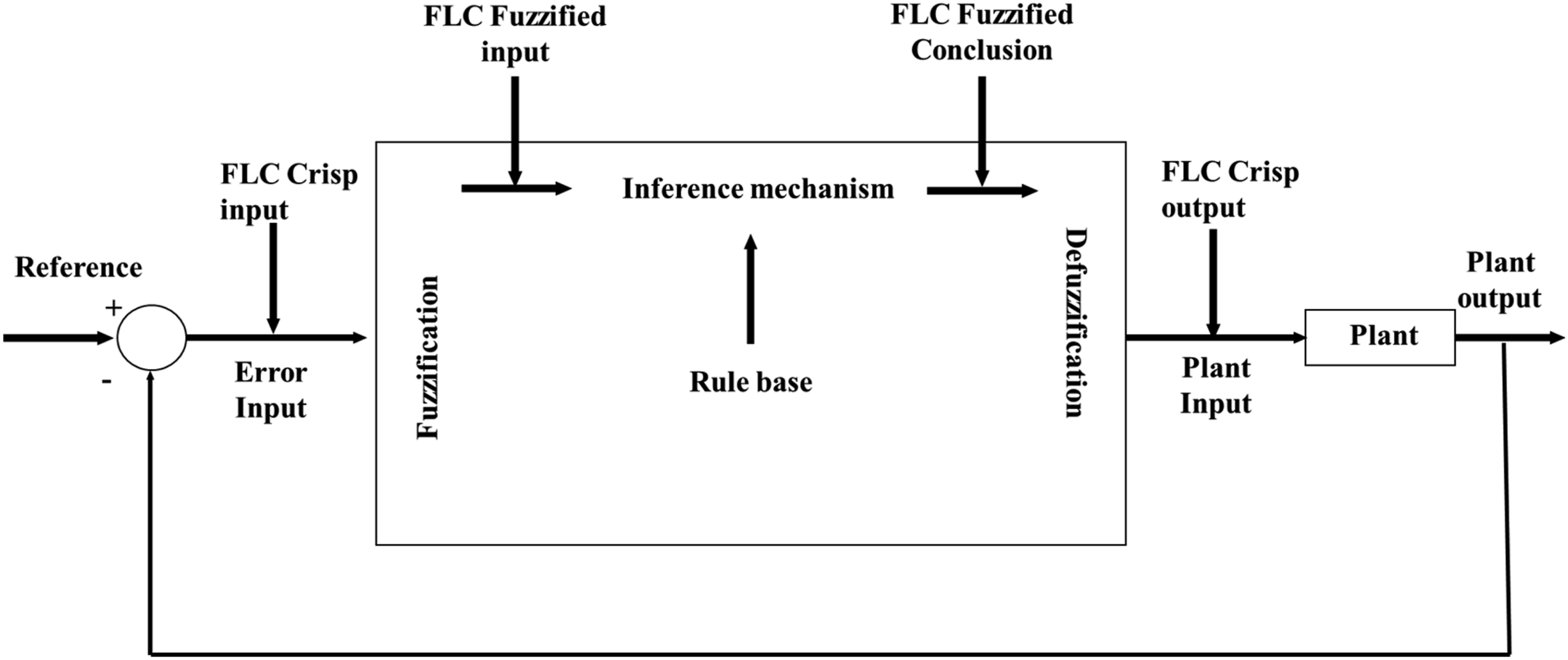

Fuzzy rule set for suspension distortion, acceleration, and velocity.
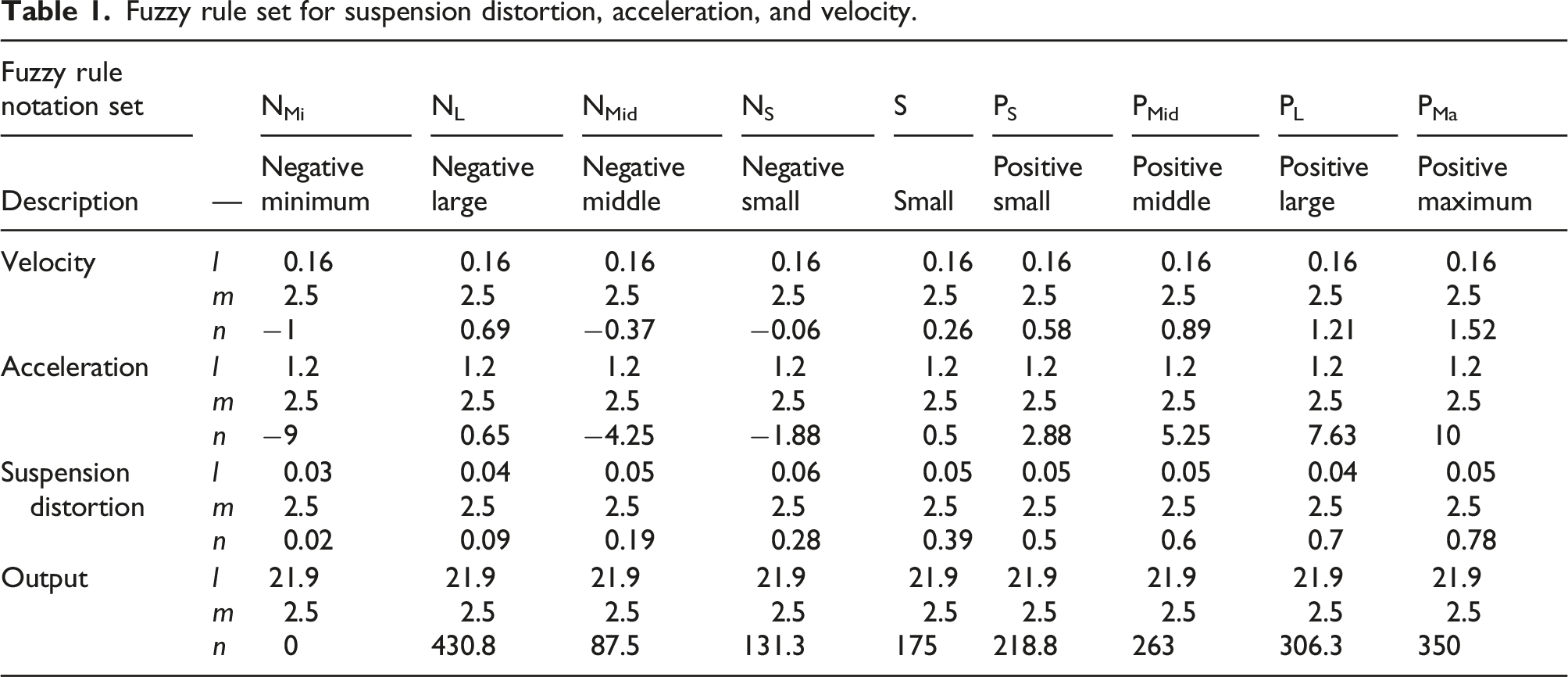
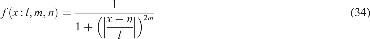
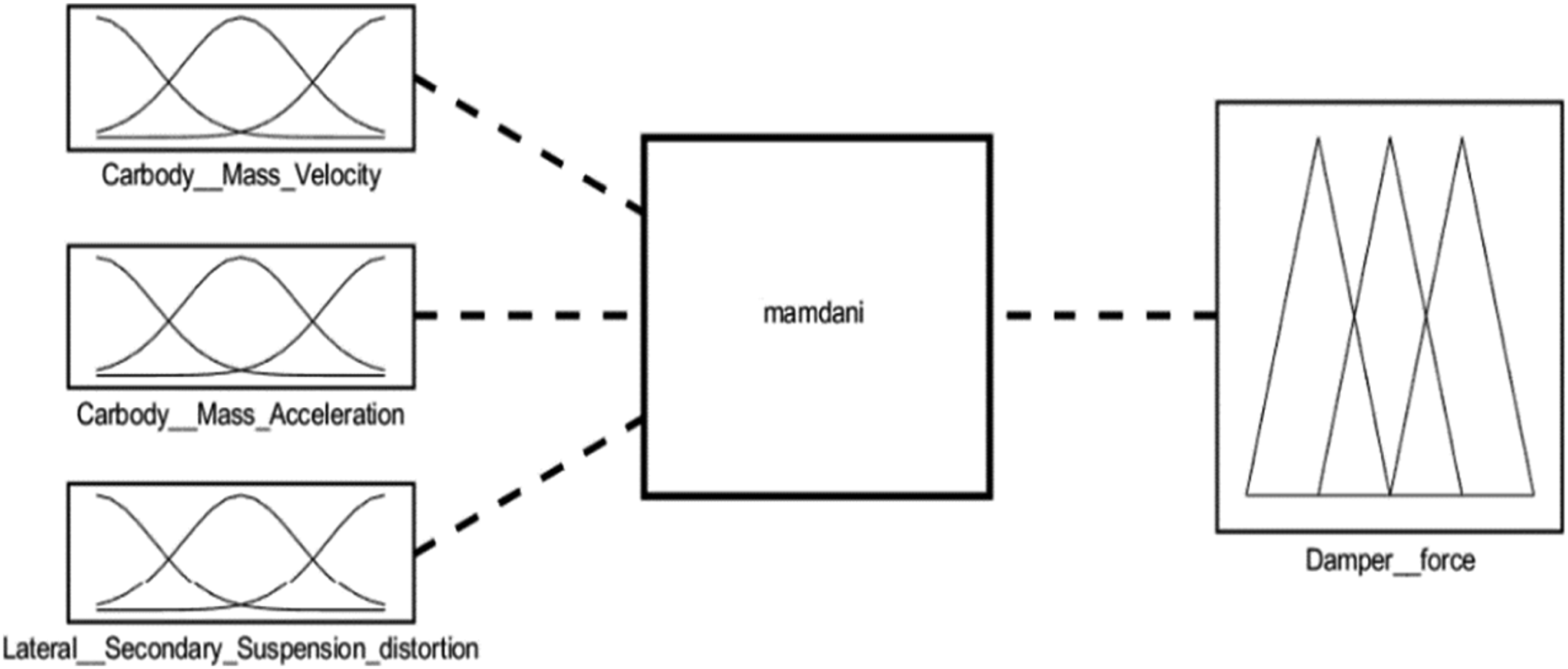
Figure 5 defines the membership for the inputs' MFs, which have a similar bell-shaped pattern but a different range of values than the inputs' MFs. The MF’s curvature is determined by the variables l and m in the equation for MF with variable x, and the curve’s center is established by the constant n. The range of numerical values and the nine linguistic notations listed in Table 2 made up the fuzzy rule set. Mamdani’s fuzzy inference approach is used to create the rule base for (9 × 9 × 9) input levels or 729 rule sets (see Figure 6). Control output of membership function. Fuzzy logic controller rule base. Control mechanism of fuzzy logic.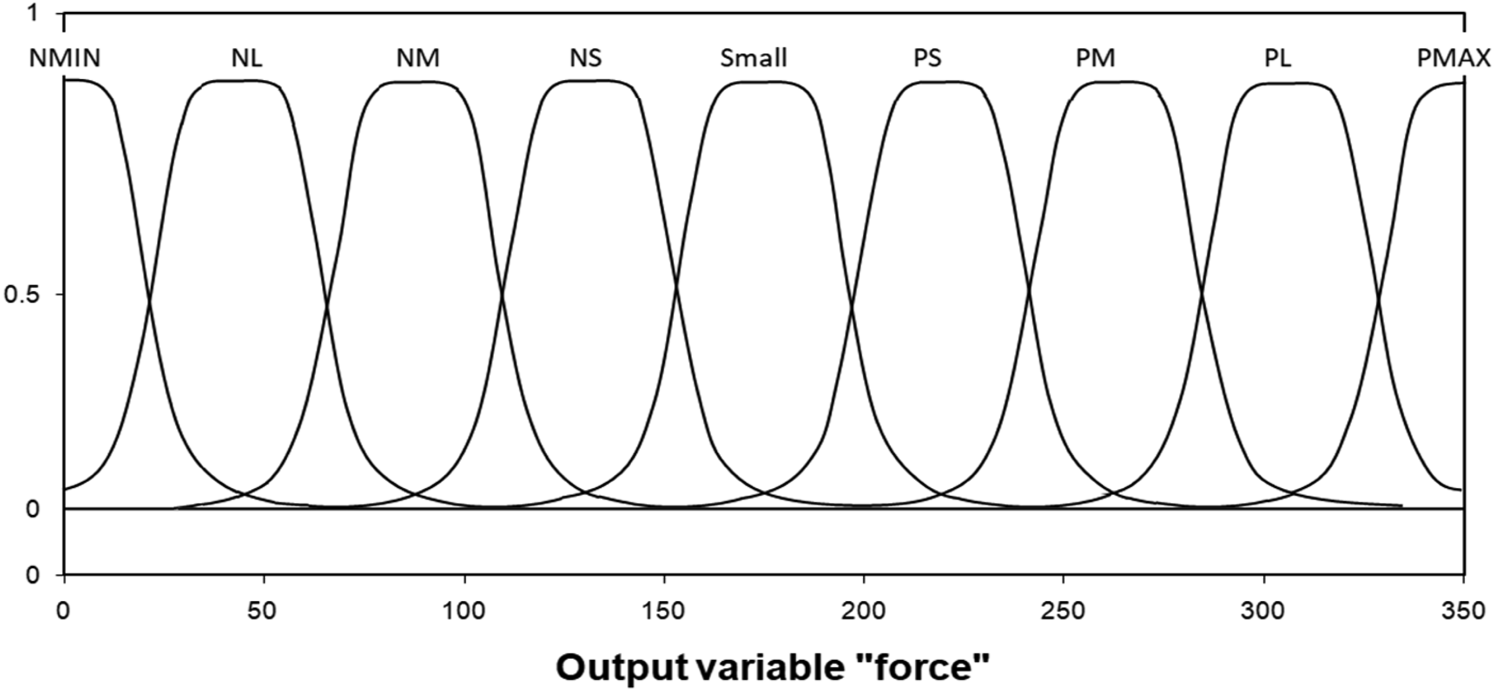
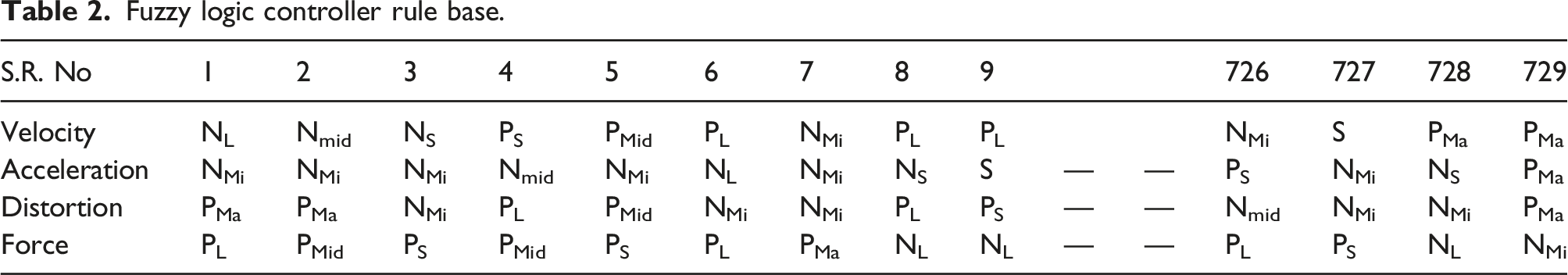
It has been determined that the control force, independent of the wide range attained by the other two inputs, is inversely proportional to the sprung mass acceleration, indicated by [Nmid∪NL∪NMi] ∪ [PMid∪PL∪PMa]. In the region denoted by [NS∪S ∪PS], the distortion and the sprung mass velocity become strong functions of the control force, and the output is evaluated depending on whose magnitude is more important. The rule foundation is summarized in 3.2.3, and Table 2 shows the range of parameter values and their implications.
Chaotic fruit fly algorithm applied to PID tuning
The behavior of fruit flies discovered in nature served as the basis for the development of the fruit fly optimization method. The fruit fly, which gets its name from the Latin word for it, Drosophila, excels in comparison to other species that are comparable, particularly in terms of food seeking employing osphresis and eyesight features. During the period of scent foraging, an individual is able to hunt for and discover potential sources of food surrounding the fruit fly swarm. The next stage is to determine, among all of the possible sources of food, the concentration of odor that most closely corresponds to the worth of fitness. 25 During the phase of vision foraging, the maximum value for the concentration of scent is assigned, and the swarm is subsequently steered towards it. The terms of agreement (FOA) may be summed up using six separate processes, that is, initiation, planning, execution, control, optimal, and generation of maximum number of generations. 27
Hence, to investigate the global objective functions, the Chaotic Fruit Fly Algorithm (CFFA) is a refinement of the Fruit Fly Algorithm which includes chaos in creating random information used to modernize the locations during optimization. The Fruit Fly algorithm is an optimization strategy that makes use of the behaviors of fruit flies in search of food. In this work, the PID controller receives the error function e(t) = r(t)-y(t) and the controller outputs O(t). The signal that triggers PID control is regarded as,
The performance of the PID is frequently described by the judgment function, which considers the factors of reducing the inaccuracy with the least amount of effort. The piecewise-defined function is given by equation (36) and comprises terms that represent the output, overshoot, and error in the PID controller. The total weights are g
1
, g
2
, g
3
, and g
4
, and tp is the rising moment when the plant output satisfies the PID’s reference input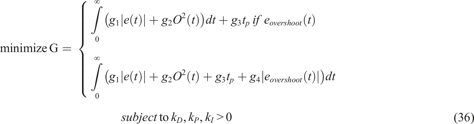
The optimized parameters were derived using the minimal judgment value. Equation (37) gives the updated position of the parameters constructed on chaotic logistic mapping in the CFFA.

Whenever the smell concentration increases, the new value of the attention is updated by calculating the minimum of the smell function. The position of the swarm shifts as a result, and the updated collection of information establishes the function’s minimum. To determine the best PID gain for the MR damper, a three-dimensional version of the CFFA is created, where equation (39) represents the location of the updated parameter determined by logistic chaotic mapping; x, y, and z denote the search space coordinates for the PID gain parameters; and k
P
, k
D
, and k
I
denote the key parameters.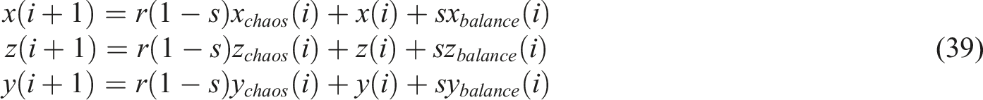
Both of the search stages are affected by the parameters, and those factors are also responsible for the creation of food sources. It is abundantly clear that the method in which they are computed in a material way has a substantial role in determining the final algorithm answer. Numerous studies have shown that random-based optimization algorithms perform better when non-standard distributions (such as the Gauss or uniform distribution) are used. In addition, the characteristics of nonrepetitional and ergodicity that chaos has may compel an algorithm to complete general searches at a faster rate. These are the primary motivations for the improvement of FOA.
28
CFFA is utilized in this study to tune the PID for controlling MR damper distortion. After random commencement for the parameter of PID, the judgment function described in equation (37) and a reduction in the dynamic performance of the isolation system strategies system was determined by its closed-loop dynamics. The improved PID parameters were returned by minimizing the judgment function. As a result, this controller follows the system controller’s force output via a series of inputs to the MR damper. The instantaneous state of the input current to the MR damper is evaluated using a continuous state technique. Figure 7 depicts the continuous state method. As a swarm is iterated, the minimum of the smell function is computed, and if the smell concentration increases, the new concentration value is updated. As a result, the swarm’s position changes, and the new data set determines the function’s minimum. A three-dimensional version of the CFFA is developed to evaluate the optimal PID gain for the MR damper, where equation (39) represents the location of the updated parameter determined by logistic chaotic mapping. An algorithm that uses chaotic fruit flies to tune PIDs in a continuous state.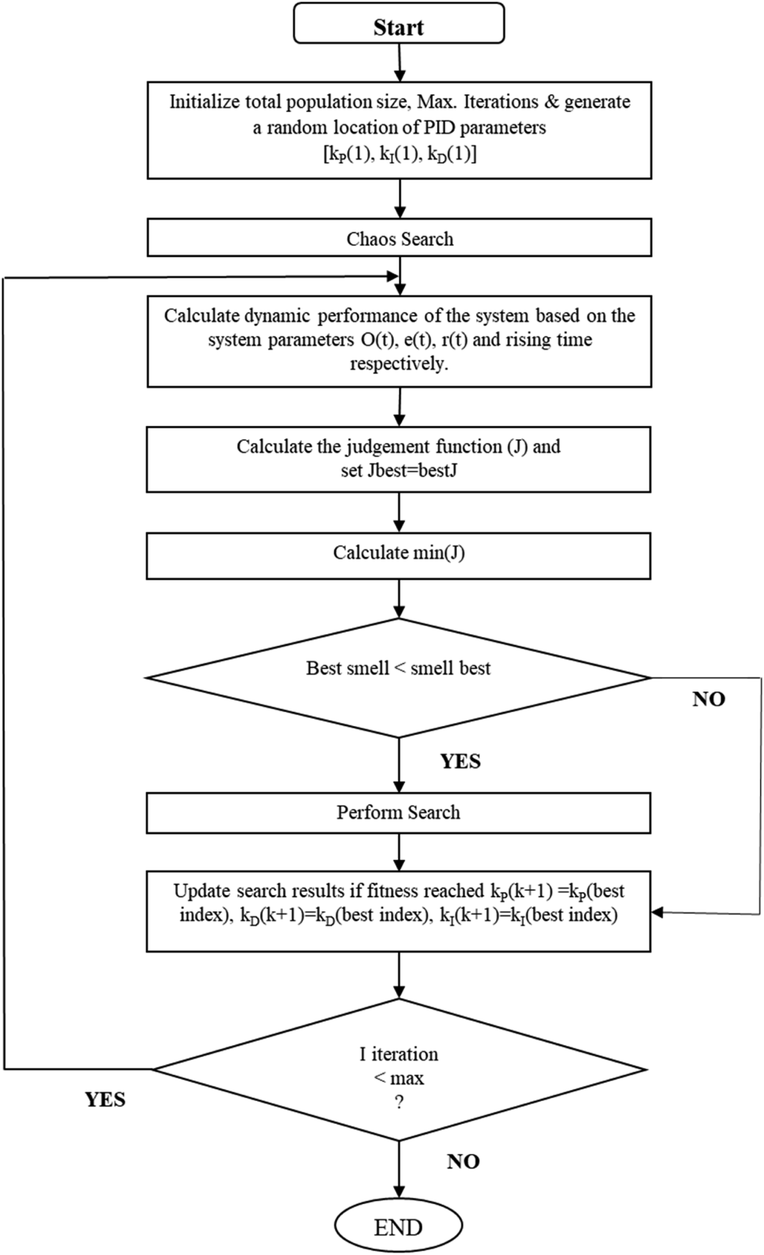
Results and discussion
Characteristics response of MR damper
The MR damper response illustrates the relationship of the hysteresis force with velocity, displacement, and time (Figure 8(a)–(c)). Based on the MR damper response, the hysteresis force is expressed as a function of velocity, displacement, and time. Based on varying current excitations of 0.25 A, 1 A, and 1.5 A at a frequency of 10 Hz, these graphs were generated in MATLAB SIMULINK with an amplitude of 6.35 mm.6,28–30 The damping force increases synchronously with increasing speed; nevertheless, the two have a certain nonlinear hysteresis. The damping force increases nonlinearly as the excitation voltage increases. Relationship of hysteresis force with (a) velocity (b) displacement (c) time.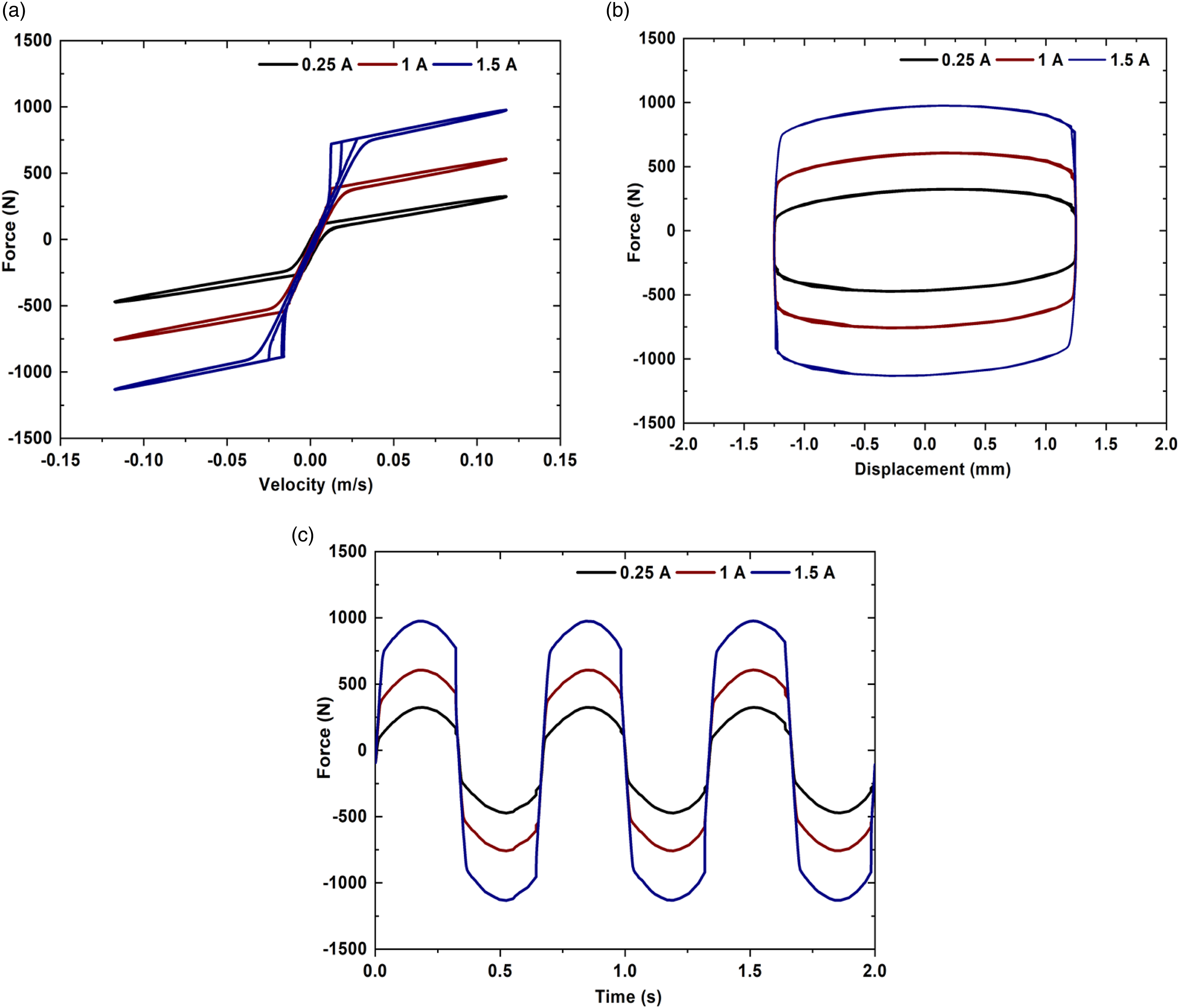
Numerical-experimental validation of MR damper
The results of the multiphysics coupling simulation of the proposed damper are compared with the experimental values at applied currents of 0.2 and 1 A to confirm the simulation’s validity. The characteristics of displacement with respect to damping force are investigated by the experiment performed by Hu et al.
31
and compared with the simulation analysis. The test setup is shown in Figure 9. Experimental apparatus for the MR damper test with linear variable-displacement transducer (LVDT) and Data Acquisition and Control (DAC) system.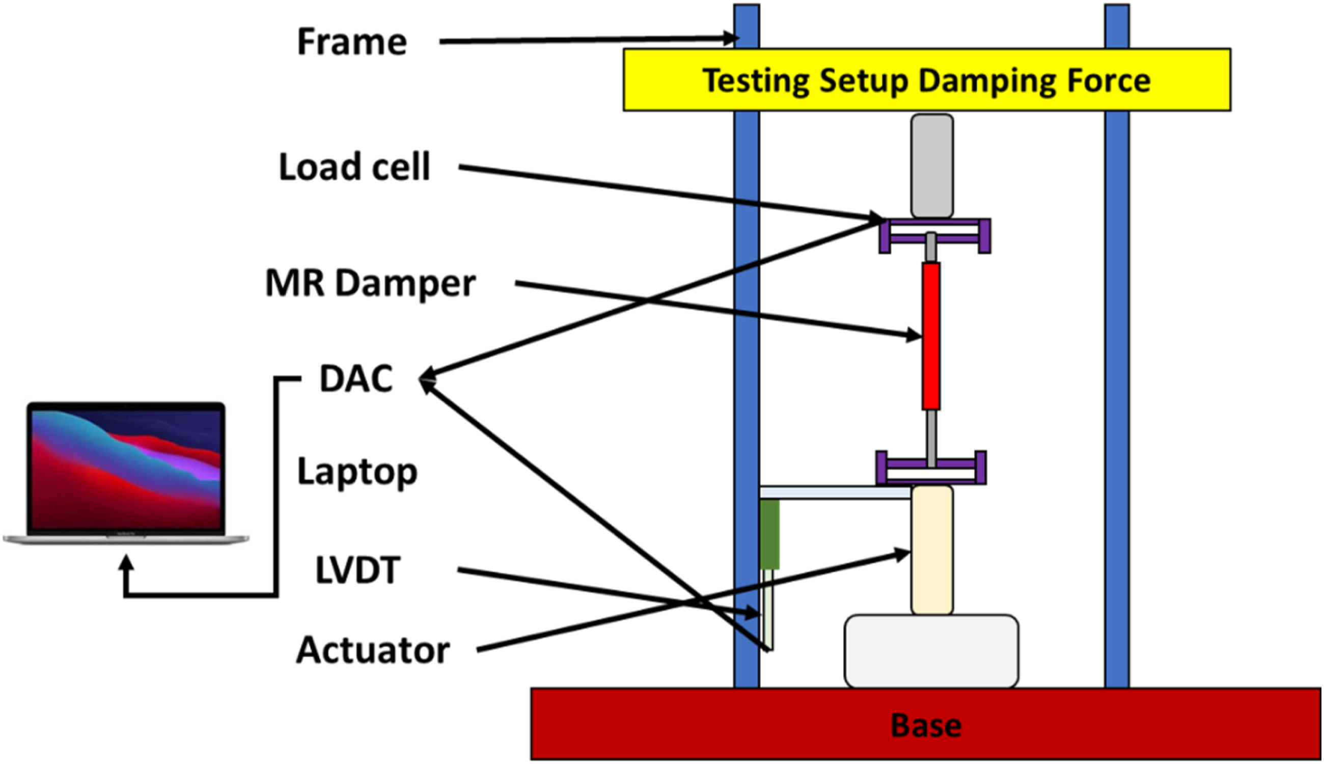
To test the influence of different currents on the output damping force of the proposed damper, the amplitude of the sinusoidal motion of the vibration excitation platform was set to 10 mm, and the frequency was 1 Hz. The damping force to displacement relationship measured in the experiment has the same variation law as that in the simulation, but the curves obtained in the experiment are not completely in the regular square distribution as in the simulation. There are different degrees of deformations at the maximum strokes of stretching and compression. The main reason lies in the fact that the MR fluid in the damper was not completely perfused during the experiment, resulting in a certain volume of air mixed into the chamber, which caused a small segment of empty path in the process of tension and compression of the damper due to the inability to compensate for the missing liquid in the chamber in time. Therefore, the displacement curves of damping force are somewhat missing. Comparing the simulation values of the output damping force with the experimental values shows that the output damping force obtained by the simulation can approximate the experiment under different currents. The comparison result verifies the accuracy of the simulation results (Figure 10). Comparison between simulated and experimental damping force versus displacement for 0.2 A and 1A of current.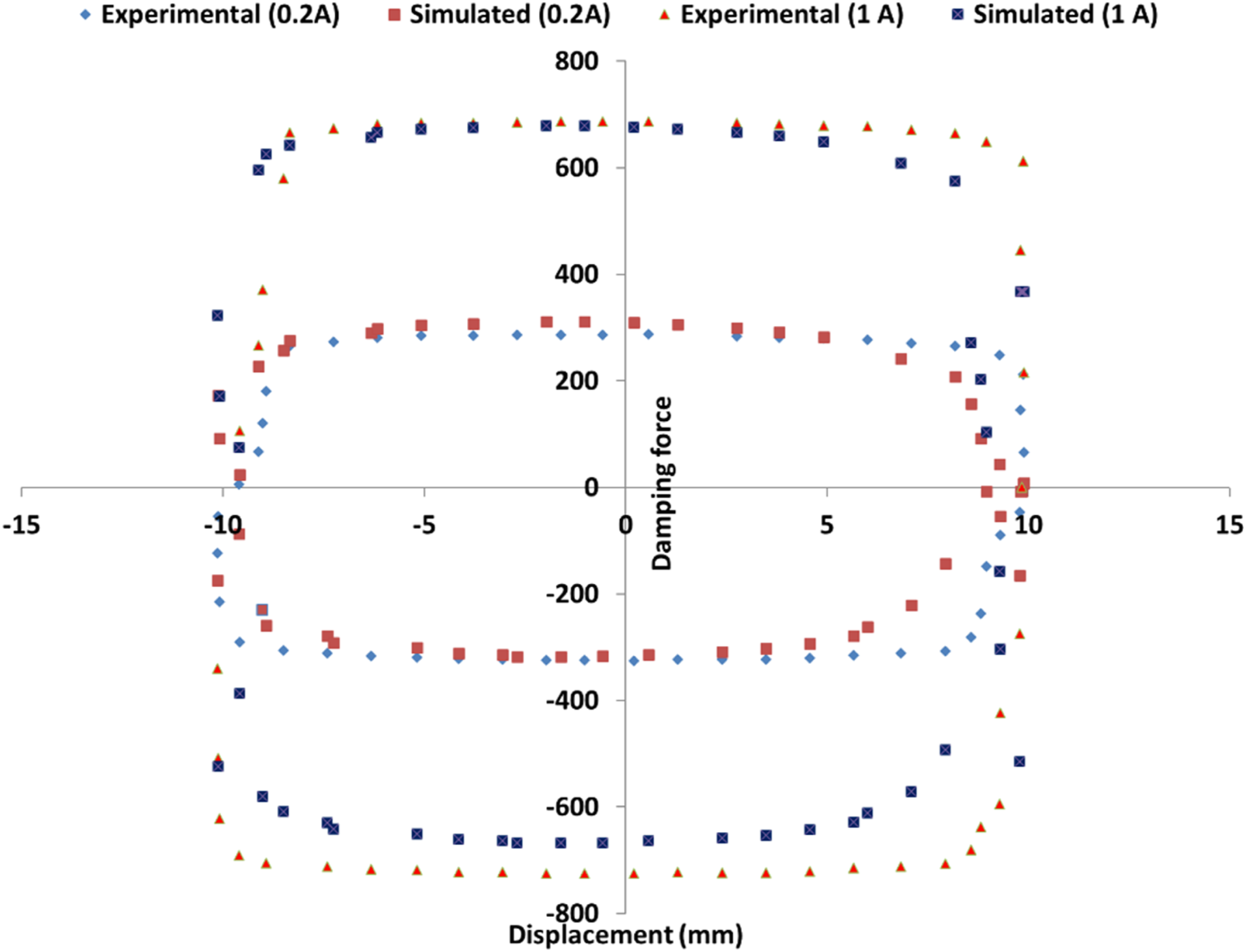
Analysis of vibration isolation systems
The vibration isolator system’s matrix equations can be expressed as
Solving the generalized eigenvalue problem yields natural frequencies and mode shapes (eigenvectors)
32


The transfer function matrix, which relates the displacement response at each DOF to the forces exerted at each DOF, is given by
A vibration isolator’s transmissibility is defined as the ratio of force transferred to the foundation to force applied on the supported mass. The force applied with the foundation is estimated by first calculating the displacements across isolators associated to the foundation caused by the force applied to the supported mass. The force exerted on the foundation is calculated by multiplying the displacements across the springs linked to it by the associated stiffness. The transmissibility of interest DOFs will vary based on the application and the extent of interaction among multiple DOFs. This is due to the location and stiffness of the isolators, as well as the supported mass’s inertial characteristics (and any intermediate masses). Reciprocating engines, for example, can be stimulated by shaking moments around the engine’s vertical and lateral axes, as well as severe torsional vibration about the engine’s longitudinal axis. In this scenario, it may be worthwhile to investigate the transmissibility of rotational DOFs on the supported mass and the resulting forces and moments on the foundation.
Steady-state response and transmission characteristics
VIS transmission characteristics and engine vibration steady-state responses are studied numerically. The engine and intermediate block weights, 220 kg and 110 kg, respectively, are the fundamental features of the VIS. Upper and lower isolator stiffness are 2400 kN/m and 3800 kN/m, crank radius is 50 mm, crank radius to connecting rod length ratio is 0.31, piston reciprocating portion mass is 0.85, and engine speed is 0–3600 r/min. Figure 11 depicts the natural frequencies for the single-stage and two-stage systems for a magnitude of forces applied to the foundation in the z (vertical) direction due to a 1 N force on the supported mass in the vertical direction. Magnitude of forces applied to the foundation in the z (vertical) direction due to a 1 N force on the supported mass in the vertical direction.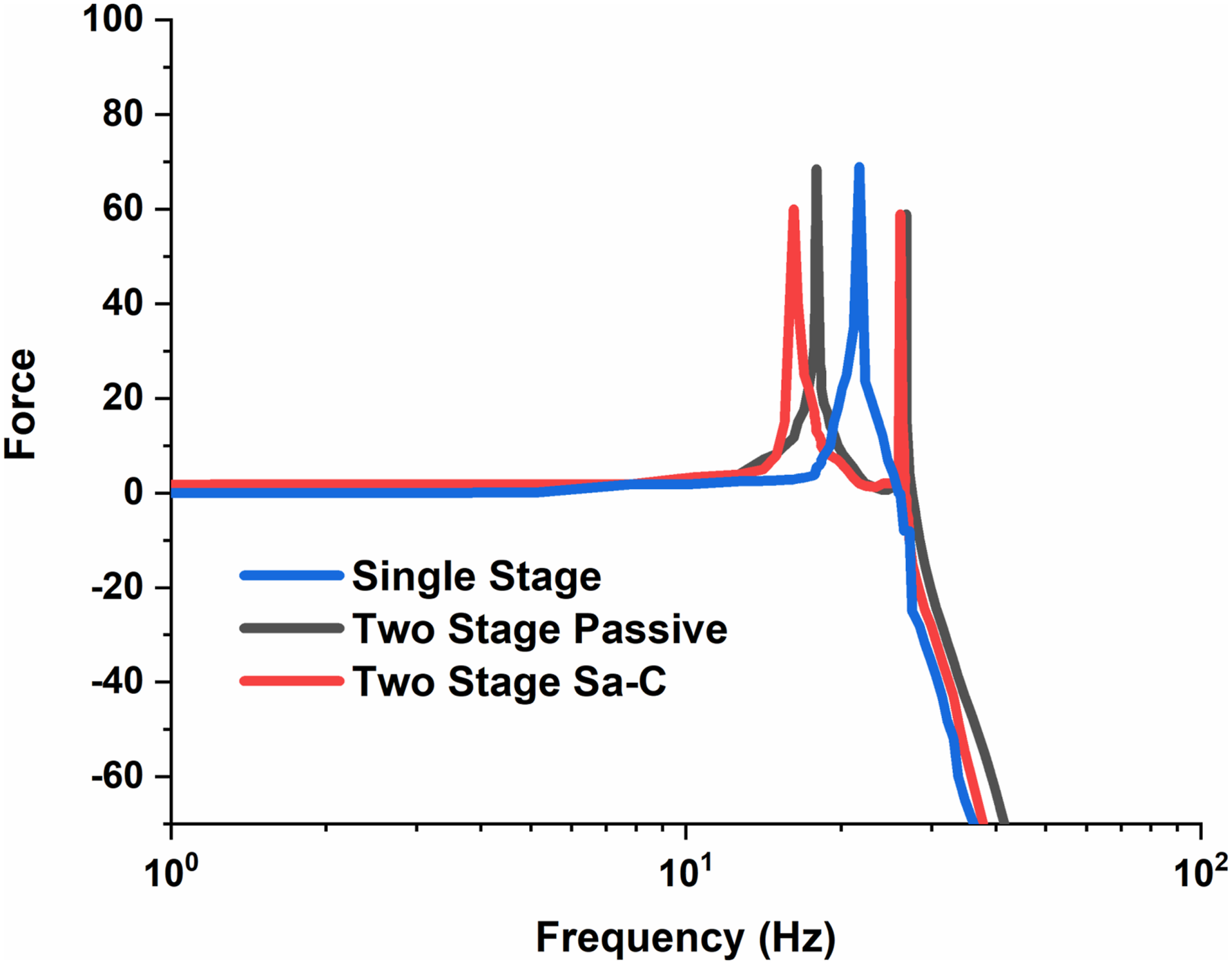
The mode forms indicate the connection among several degrees of freedom at each natural frequency. When the system damping is ignored, the inherent features of the passive two-stage VIS are estimated. The results demonstrate that the system’s vertical natural frequencies are 11.3 Hz and 18.26 Hz, respectively. The two-stage systems exhibit a sharper roll-off of transmitted force at higher frequencies than single-stage systems. However, the additional degrees of freedom in the two-stage systems result in more modes, forcing frequencies close to the natural frequencies to impact the VIS performance negatively. Therefore, care must be taken to ensure that forcing frequencies are not aligned with the natural frequencies associated with any of the isolation system’s vibration modes. The two-stage method has the drawback that modes with a considerable motion of the intermediate masses occur at high frequencies compared to modes with a motion of the supporting mass. This is due to the mass difference and can be improved by using an MR damper. Due to the presence of dampening, the natural frequencies of the semi-active control system will alter significantly when the MR damper is added.
Force transmitted characteristics from dynamic models
Figure 12 depicts the force transferred to the base under different control techniques at different r/min speeds of 400, 800, 1200, 1600, 2000, 2400, 2800, and 3600 in the simulation analysis. The force communicated to the base is greatly decreased when the Sa-C is used at varied speeds compared to the other isolation system strategies. The results reveal that Sa-C has a better isolating effect than passive control. Force transferred to the base under different control techniques at different r/min speeds of 400, 800, 1200, 1600, 2000, 2400, 2800, and 3600.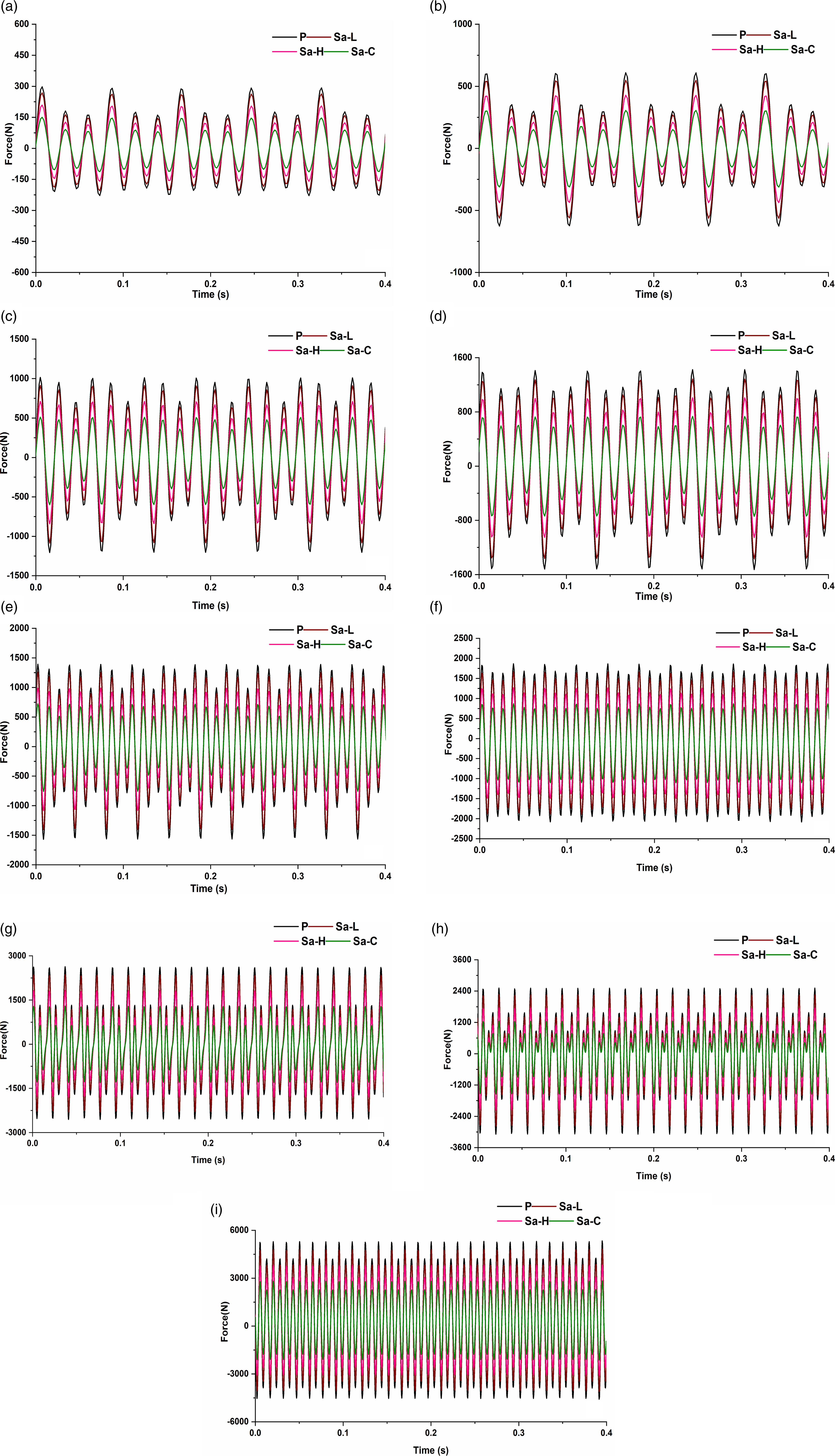
Rotation speeds exceeding 400 r/min, 800 r/min, or 1200 r/min are considered as resonance values, which means that the transmission force exceeds the excitation force, resulting in amplified system response. A Sa-C isolation system reduces transmitted force in the resonant frequency range. Both vibration isolation techniques have a great effect when the speed increases. The comparative performances as shown in Figure 12, the force Root mean square, and percentage reduction between the reduction strategies at different speeds are investigated. It can be seen from these graphs that there is an improvement in the performance after the implementation of a semi-active suspension strategy. The semi-active suspension strategies have better reduction than the passive system in all the cases. An improvement about 0.8–6.16% for Sa-L, 2.4–8.28% for Sa-H, and 5.6–15.174% for Sa-C can be observed. Therefore, the semi-active–controlled system is far more superior in performance as compared to the other strategies.
Force transmission ratio characteristics
Figure 13 depicts the force transmissibility at various speeds and control techniques and the ratio of the force transferred to the base to the excitation force. The semi-active isolation system with Sa-C outperforms the passive isolation system regarding vibration reduction over the whole frequency range. Force transmissibility at various speeds with different isolation system strategies.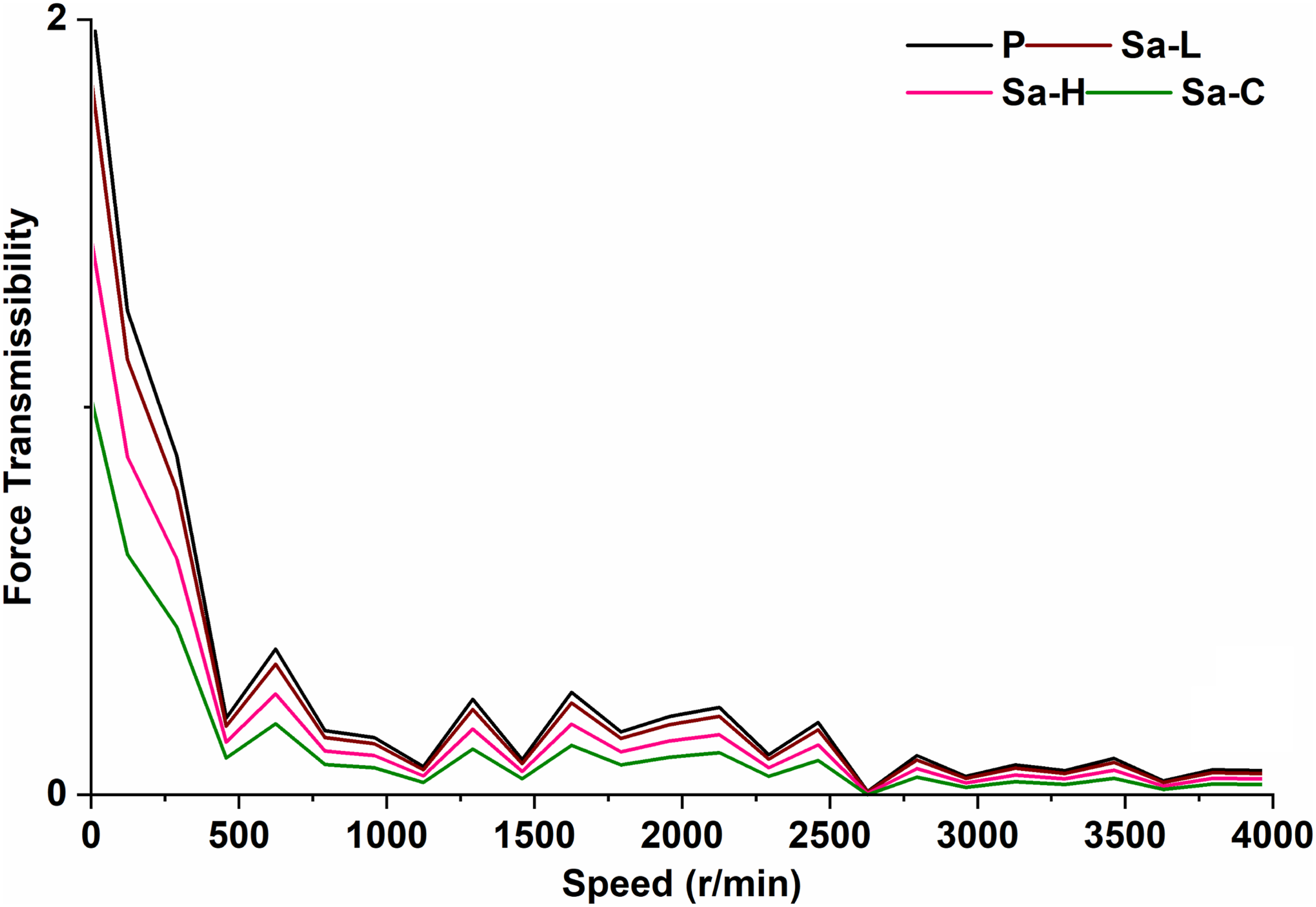
If resonance exists, the semi-active adjustment of the MR damper may effectively suppress the resonance peak. The force transmissibility at different speeds is shown in Figure 13, which is the ratio of the force transmitted to the base to the excitation force. It can be seen that the vibration reduction performance of the semi-active isolation system with optimal control is better than that of the passive isolation system in the whole frequency band. Especially in the case of resonance, the semi-active control of the MR damper can suppress the resonance peak obviously. At the second resonance frequency, the force transmitted to base by optimal control is less than the excitation force. Near the first resonance frequency in the low-frequency region, the transmitted force is more than the excitation force. Generally speaking, the excitation force of the first natural frequency in low-frequency band is relatively small, so the system response will not be excessive.
Conclusion
In this paper, a semi-active nonlinear artificial intelligence compound controller for marine engines was mathematically developed to improve vibration reduction characteristics across a wide frequency range. Moreover, a mathematical model was developed and investigated for two-stage VIS. The force versus displacement responses are validated using the experimental analysis. Force transmitted from the engine to the base was evaluated on the validated model using four different strategies, that is, conventional passive, semi-active low, semi-active high, and semi-active controlled damper. In a semi-active–controlled damper, a mathematical model is developed for controlling the force by developing NAICC using the CFFA and fuzzy logic control. The results show that the application of NAICC has a better isolating effect than the passive VIS over a wide spectrum of frequencies. By establishment of the control effect in the low-frequency resonance zone, marine engine vibration reduction performance was significantly enhanced.
Footnotes
Declaration of conflicting interests
The author(s) declared no potential conflicts of interest with respect to the research, authorship, and/or publication of this article.
Funding
The author(s) disclosed receipt of the following financial support for the research, authorship, and/or publication of this article: This work was supported by a grant from Brain Korea 21 Program for Leading Universities and Students (BK21 FOUR) MADEC Marine Designeering Education Research Group.