
Abstract
As an important component of inlet and exhaust mufflers, the acoustic characteristics of perforated components are inevitably affected by the flow of air. Therefore, obtaining the acoustic impedance of the perforated element under airflow conditions is a prerequisite for accurate calculation of the muffler’s muffling performance. In this work, the frequency domain linear Navier–Stokes (L-NS) method is used to extract the acoustic impedance of perforated plates under grazing flow. The predicted perforated acoustic impedance is consistent with the calculation results of published acoustic impedance expression, and the impedance boundary condition is defined to calculate the transmission loss (TL) of the perforated muffler, which agrees well with the experimental results and verifies the accuracy of the method. The effect of perforation angles on the transmission loss of mufflers in different Mach numbers (Ma) and aperture plate thickness ratio (dh/tp) is analyzed by the frequency domain L-NS method. The results show that when 1≤dh/tp<2 and Ma≤2, the effect of perforation angles on the muffler performance is obvious, and the angle tilted upstream shifts the resonant frequency to a lower frequency while its corresponding peak value is also increased. As an engineering application, it has certain significance for the prediction of muffler muffling performance and the regulation of the muffling frequency band.
Keywords
Introduction
Perforated elements are widely used in inlet and exhaust mufflers1–3 and combustion systems4,5 to improve the muffling performance in a specific frequency range, reduce flow resistance 1 and prevent thermoacoustic oscillations.6,7 The application context of this paper is to analyse the effect of grazing over-flow on the muffling performance of perforated mufflers at room temperature, so the acoustic impedance of perforated elements8–10 is necessarily influenced by the flow factors near the perforated plate and the resulting eddy currents7,8 are the main mechanism affecting sound dissipation.
In recent decades, the perforated acoustic impedance under grazing flow has attracted the attention of many scholars. The research methods mainly include: theoretical analysis, experimental measurements and numerical calculations. Howe 11 theoretically investigated the effect of swept flow on the acoustic conductivity of small holes and gave an analytical solution for the acoustic conductivity, but made more assumptions in the derivation process, resulting in a large difference from the experimental values. Jing 12 et al. used the relevant theory of Howe 11 and used the displacement continuum condition to study the acoustic impedance of perforations at a specific Mach number. The theoretical calculations were in good agreement with the experimental measurements, but the distribution of acoustic impedance with frequency was not given. Based on Jing, 12 Peat 13 summarised the variation of acoustic impedance with the Strohal number (St) under the action of grazing flow by setting up displacement continuity conditions and velocity continuity conditions, it is not reasonable that the perforated acoustic impedance as a whole but requires different continuity conditions. Recently, Meng 14 derived a semi-empirical formulation for perforation using a linearised potential flow model, but the model predictions only agreed well with experimental measurements at low St. Zhao 15 developed a one-dimensional theoretical model of the pneumatic-acoustic damping effect of a perforated plate in the case of biased flow by modifying the Cummings equation for non-constant flow with the Cargill equation for acoustic open boundary conditions at the end of the pipe. Guan16,17 studied the acoustic damping performance of single and double coaxial perforated plates and double off-axis perforated plates at low Mach number and Helmholtz number based on acoustic theory and experiments, and summarised the influence of structural parameters of double perforated plates on their acoustic damping performance, but there are some differences between the theoretical model and experimental values of double perforated plates, mainly because it is difficult to consider the vortex effect. Yang 18 developed an impedance model for the lining of elongated pipes under the action of grazing flow based on the transfer matrix method, which provides better accuracy in predicting transmission loss. In practice, mathematical models that can fully account for the effect of flow-acoustic coupling on the acoustic impedance of grazing flow are difficult to develop. Rao, 19 Gummings 20 and Kirby 21 experimentally measured the acoustic impedance of perforations under grazing flow conditions and obtained a variety of empirical formulae for acoustic impedance, but different impedance extraction strategies and flow boundary conditions led to significant differences in the acoustic impedance of small holes calculated by these empirical formulae. With the development of computer technology and simulation software, numerical methods are able to characterise the above conditions very well. Tam 2 calculated the effect of slit resonator acoustic performance by direct numerical modelling (DNS) to study the reflection coefficients of slits at different tilt angles, and their calculated results agreed well with experimental test values, demonstrating that DNS is a useful and accurate tool for linear aerodynamic acoustic prediction. Zhang 3 calculated the interaction of the laminar and turbulent boundary layer states with the liner bore by DNS at different incident sound field parameters and with the laminar and turbulent boundary layer states, and showed that the bushing increases the drag with increasing incident sound pressure amplitude for all conditions studied. For practical applications, Zhong and Zhao 22 developed a one-dimensional time-domain numerical model to simulate the propagation and dissipation of acoustic plane waves in a cylindrical lined pipe, and the results of the model agreed well with previous experimental and frequency domain results. Ji and Zhao 23 applied the lattice Boltzmann method (LBM) to study the acoustic damping effect of circular holes in pipes, which not only has higher accuracy but also improved computational efficiency compared with the conventional NS solver. Ji, 24 Liu 25 and Zhu 26 predicted the transmission loss of perforated muffler in the presence of airflow using the time-domain CFD method, and the calculated results agreed well with the experimental measurements, which confirms the accuracy of the time-domain CFD method, but the time-domain CFD method has low computational efficiency, so its application in the actual design of muffler is limited. As a result, some researchers27–29 have fitted acoustic impedance expressions by time-domain CFD methods to improve computational efficiency, Zhang 27 used the time-domain CFD method to study the linear relationship between the internal flow parameters and the flow-related terms in the acoustic impedance formula, and established the acoustic impedance expression within a certain flow range. Chen28,29 used the time-domain CFD method to study the effect of structural parameters and vortex velocity in the hole on the acoustic impedance, calculated the contribution of the perforated plate to the acoustic impedance of the bias-flow and grazing flow conditions, and fitted an exact expression for the perforated acoustic impedance, and the calculated muffler transmission loss agreed well with the experimental value in most cases, but because of the limitation of the extraction method, it is not suitable for the case above 0.2 Mach number. Therefore, this paper will use the L-NS equation to solve the perforation acoustic impedance in the frequency domain, Chu 30 and Ullrich 31 proved that the L-NS equation can characterise the linear propagation process of acoustic wave, vortex wave and entropy wave, and the interaction between the three acoustic modes and the mean flow. Xin 32 found that turbulent viscosity is an important effect on the coupling of flow and acoustics when solving the L-NS equation in the frequency domain. Zhao 33 and Huang 34 predicted the transmission loss of the muffler using the L-NS equation, and the calculated results were in good agreement with the experimental values. Toulorge 35 used the frequency domain L-NS equation to calculate the incident and radiated acoustic impedance of a square perforation at low flow rates, and studied the influence of the width, thickness and edge shape of the square perforation on the dimensionless acoustic impedance. However, Toulorge 35 selected a more complex acoustic impedance extraction method, the calculation method occupied a higher computer memory. Ou 36 developed the impedance boundary Navier–Stokes equation (IBNSE) method to predict the absorption characteristics of acoustic ducts with grazing flow.
In this work, the perforation acoustic impedance is calculated using a frequency domain approach under grazing flow. The main structure is as follows: The second section describes the theory and extraction method of the perforated acoustic impedance under grazing flow. The third section introduces the establishment and meshing of the perforation flow field model under grazing flow, analyzes the velocity distribution and shear rate near the perforation and maps the flow field information to the acoustic field model. The fourth section introduces the calculation method of the perforated acoustic field model under grazing flow, compares the calculated perforated acoustic impedance with the theoretical value, and compares the transmission loss of the muffler with the experimental value. The fifth section summarises the effect of perforation angle on transmission loss under grazing flow.
The extraction method of perforation acoustic impedance
For the circular perforation shown in Figure 1, the acoustic impedance
8
is defined as Acoustic quantities on both sides of perforation.

In the formula,
To obtain the sound pressure at the inlet and outlet of the perforated plate and the volume velocity in the hole under grazing flow in COMSOL, it is necessary to establish a suitable model of the flow field and the acoustic field, and the non-local coupled integration of the sound pressure in the sound field and the boundary where the volume velocity of the central section of the perforation is located. The volume velocity in the perforation is expressed as The boundary of inlet, outlet and hole of perforated plate.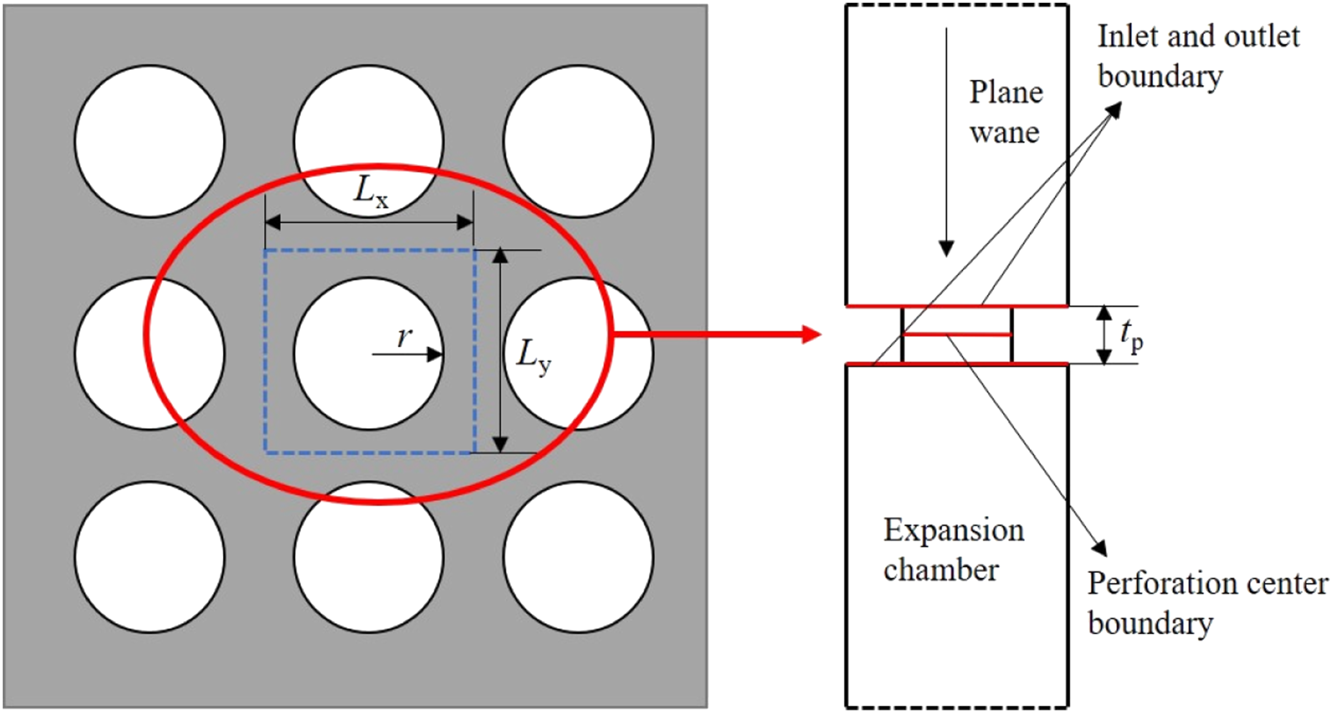
Among them, r is the perforation radius, tp is the plate thickness and Lx and Ly are the x-direction spacing and y-direction spacing of the centre line between the perforations, respectively. The plane wave is incident from the perforated inlet section and simulated by the ‘background sound field’ feature in the ‘linear Navier-Stokes, frequency’ interface. When extracting in the three-dimensional frequency domain L-NS, it is necessary to define the perforation acoustic impedance extraction formula, that is


In the formula,
Flow characteristics analysis and information mapping
Computation module
In this section, the velocity distribution and shear rate distribution at the perforation are analyzed in detail. The structural parameters of the perforated plate used in the section are as follows: perforation diameter dh = 6 mm, plate thickness tp = 2 mm and porosity φ = 15%.
The flow field calculation model includes the main pipe, perforations and side branch pipes, the perforations are placed at the bottom of the main pipe, the airflow flows through the upper side of the perforations, the flow medium is an ideal gas at room temperature, the stress tensor and linearised equation of state
37
is expressed as


The upstream pipe of the main is 150 mm long and the inlet is set to fully developed flow to allow the turbulent boundary layer to fully develop and the downstream pipe is 50 mm to allow the shedding vortex to be fully depleted. The fluid calculations are modelled using SST RANS in the CFD module of COMSOL, which has a greater advantage in solving for free shear flow and boundary layers, and the velocity boundary conditions for the inlet can be written as

In order to skim the effect of over-flow on the acoustic impedance of the perforation, it is necessary to define the background mean flow temperature T0, the absolute pressure p0 and the velocity field

The use of hexahedral structural grids can obtain accurate calculation results and reduce calculation time. Figure 3 shows the flow field grid model of the perforated plate acoustic impedance calculation model. The mesh size of the main pipeline is 1 ∼ 2 mm. The thickness of the first layer of the boundary layer on the upper side of the perforation is divided according to the principle of y+≈2. The thickness is between 0.05 ∼ 0.1 mm, and the boundary layer is at least 15 layers. The minimum mesh size in the X-axis direction is 0.07 mm, and the mesh size in the Y-axis direction is 0.33 mm. Due to the symmetry of the perforated model, symmetric surface boundary conditions can be used to reduce the degrees of freedom of the calculation in order to improve computational efficiency. Based on the above meshing principles, the total number of meshes is 103,334. The following comparison with the experimental data
29
from the references demonstrates that the number of meshes is sufficient. Flow field grid model.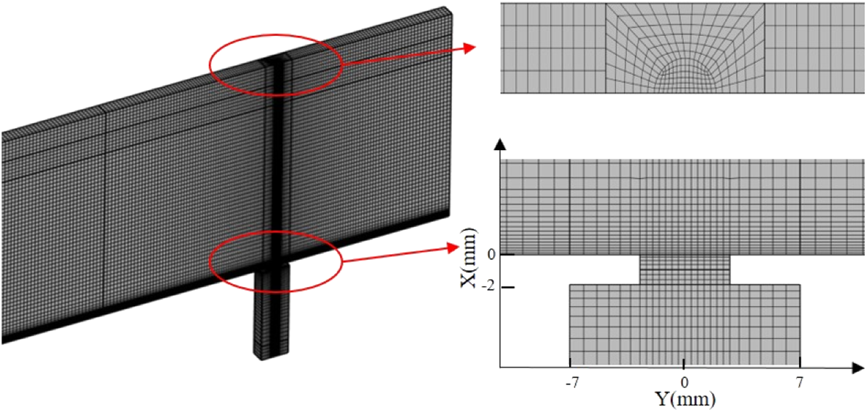
Flow field information at the perforated plate
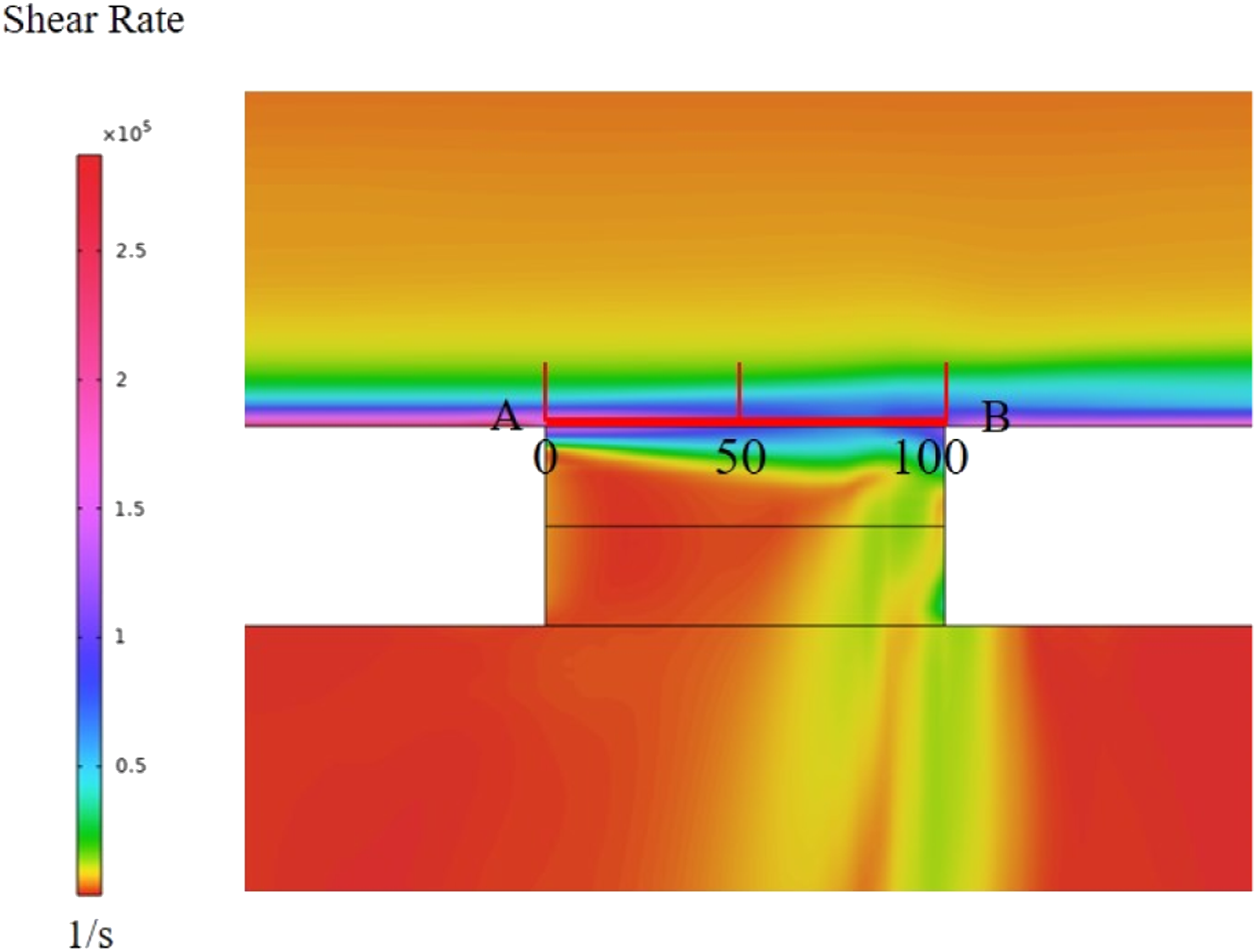
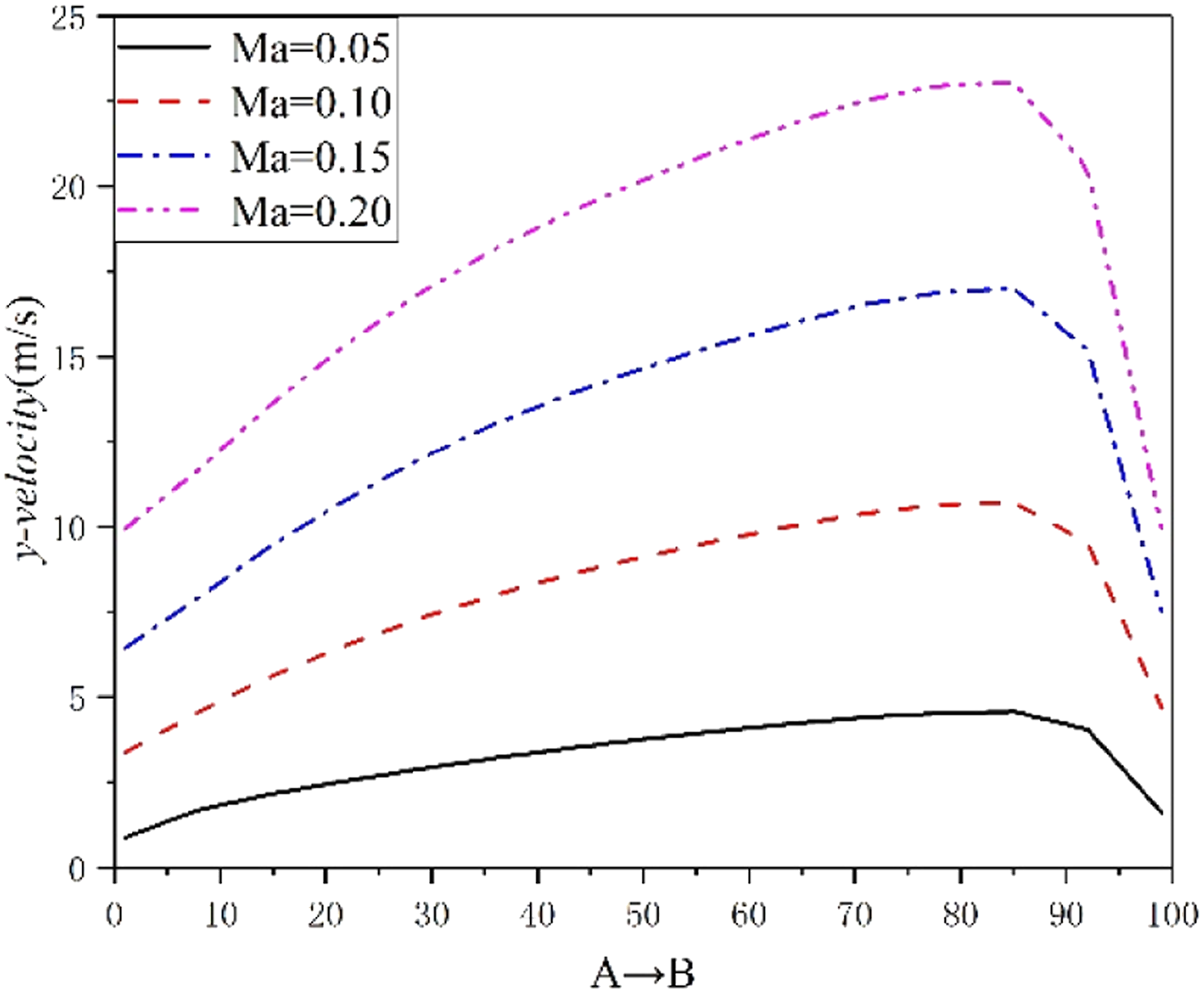
This section investigates the gas flow phenomenon at the perforation in terms of both the surface velocity and shear rate on the perforation, respectively. Figure 4 shows a cloud of the steady state flow velocity distribution near the perforated plate for a grazing flow Mach number of 0.1. It can be seen from the diagram that almost all of the air flows sideways from the perforated plate, forming a velocity buffer zone in the downstream region of the perforation, while a small amount of gas enters the side branch pipe through the perforation, and the airflow in the side branch pipe is very small. As shown in Figure 5, the airflow forms a clearly layered shear layer on the upper surface of the perforation, which has a large effect on the perforation acoustic impedance due to the perturbing effect of the shear layer and the acoustic waves. To study the shear layer flow phenomenon near the perforated plate in detail, the distribution of y-velocity in y-direction is studied at the line segment AB on the upper surface of the perforation. According to the research of some scholars, the eddy current is usually distributed in the shear layer of the upper surface of the perforation. The velocity of the eddy current is the fluid velocity in the shear layer of the upper surface of the perforation, which gradually increases with the increase of the grazing flow Mach number. (Figure 6) Velocity cloud near the perforated plate. Distribution of shear rate near the perforated plate. Velocity distribution on line segment AB at the perforation.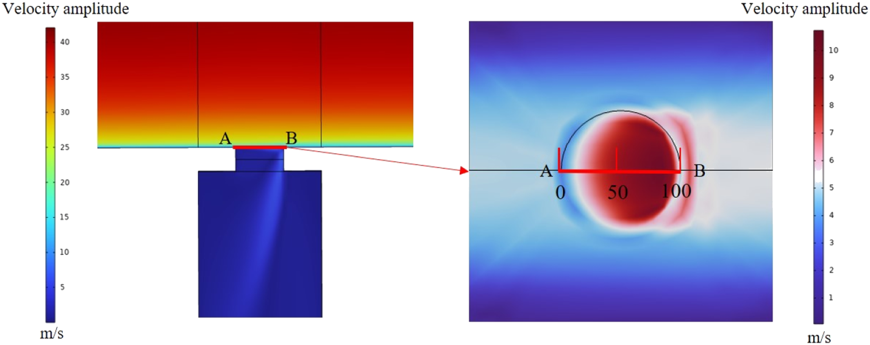
Flow field information mapping
The flow field information is mapped to the acoustic mesh by multi-physics field coupling
38
in COMSOL, and the solution of the flow field information in the CFD mesh is compared with the mapped solution on the acoustic mesh below. A three-dimensional section line is selected along the perforation centre in the y-direction of the main pipeline. The mapping results on the section line are transformed into a one-dimensional chart form, which can intuitively judge the accuracy of the mapping results. Figure 7 shows the comparison between the axial (cross-section direction) internal velocity calculated on the CFD grid and the mapping results on the acoustic grid. The flow field information solution is almost consistent with the mapping solution curve. In the flow field information, the turbulent viscosity is an important factor in the interaction between the reaction flow and the acoustics. Therefore, the map shows that the turbulent viscosity distribution calculated on the CFD grid is compared with the mapping results on the acoustic grid. The change of the flow field information solution and the mapping solution curve is almost the same. Comparison of mapping results. (a) Axial velocity; (b) Turbulent viscosity.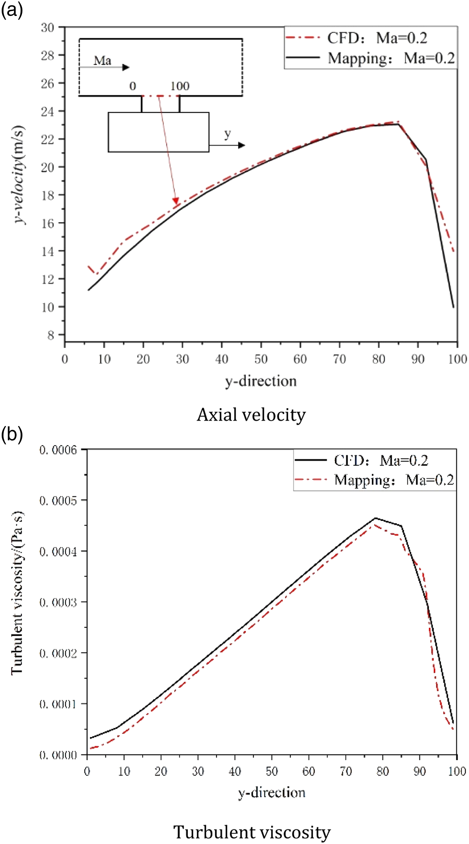
Sound field calculation and model verification
The equations solved in acoustic calculations are the linearised Navier–Stokes equations
39
given in the frequency domain, as follows


The acoustic calculations are made in 10Hz frequency steps and include all of the following. The acoustic calculation model does not require the overall flow field model. As shown in Figure 8, a part of the main pipeline is intercepted with the size of the side branch pipeline as the constraint. The flow field information is automatically mapped to the interception part. A non-reflective end is added at the end of the interception model to avoid the reflection of sound waves in the pipeline and affect the accuracy of the extraction results. A background sound field is applied near the end of the perforation to generate a plane wave signal. The plane wave variable40,41 is defined as follows Acoustic calculation model.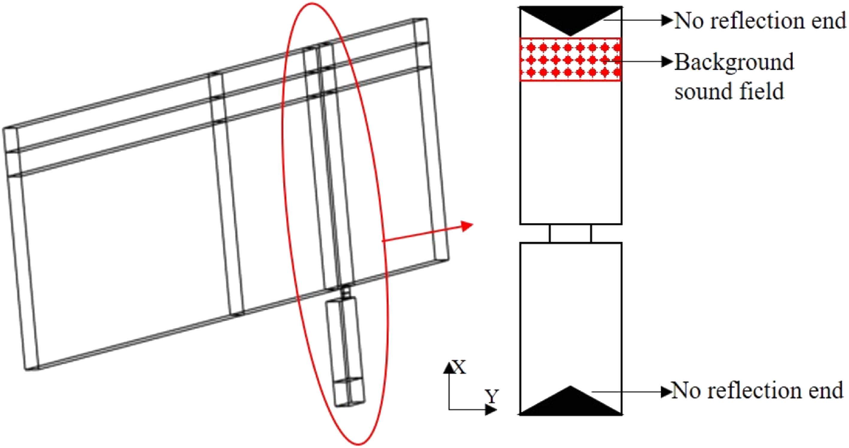


To verify the accuracy of the acoustic impedance extracted by the L-NS equation in the frequency domain, the calculated results are compared with the acoustic impedance fitting equation given by Chen
29
under grazing flow. Figure 9 shows the curve of acoustic impedance and acoustic impedance changing with the Strohal number St for Mach number is 0.1 and 0.2. It can be seen from the figure that when St is small, the grazing flow increases the acoustic resistance of the perforation and the acoustic energy absorbed by the perforated plate increases, and when St exceeds 0.7, the acoustic resistance drops to a negative value, indicating that flow noise is generated at the small perforation; when St is small, the grazing flow reduces the acoustic resistance of the perforation, and as St increases, the acoustic resistance increases sharply. The model of perforated plate (L-NS) and Chen
29
calculate the results of the change of trend and numerical match well, but there is a numerical error at high St, which is acceptable. The following will indirectly prove the accuracy of the model of this paper (L-NS) by calculating the transmission loss of perforated muffler. (Table 1) Comparison of acoustic impedance and acoustic reactance. (a) Ma = 0.1; (b) Ma = 0.2. Structure size parameters of perforated tube muffler (unit: mm).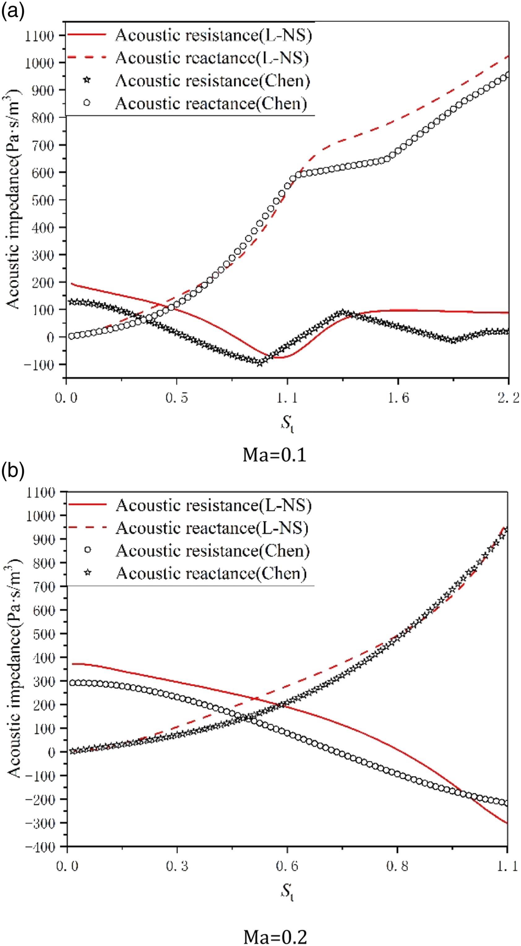
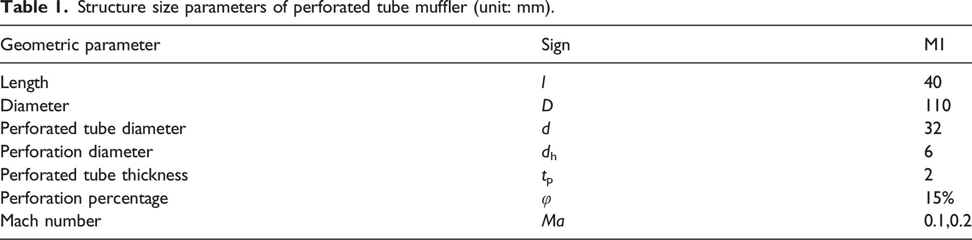
To further verify the accuracy of the perforation acoustic impedance extraction method in this study, the transmission loss of the perforated pipe muffler will be calculated by applying the obtained acoustic impedance to the perforated plate through the finite element method and comparing it with the experimental test value. (Figure 10) Structure diagram of the perforated muffler.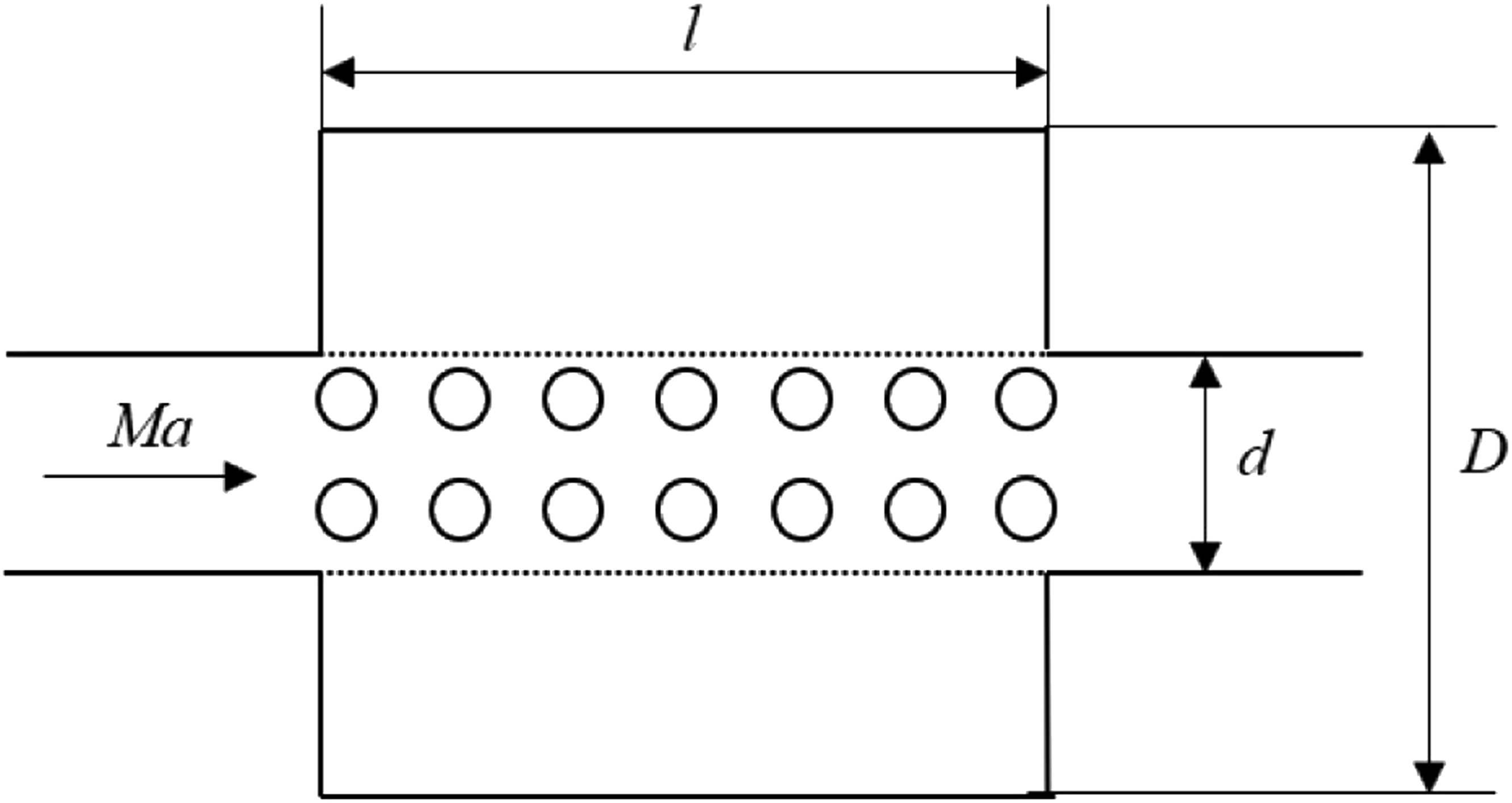
Figure 11 shows the model (L-NS) and Chen
29
compared to experimental measurements for Mach numbers of 0.1 and 0.2. The muffler M1 has a small aspect ratio, and the transmission loss curve shows only one resonance peak in the range of 0–4000Hz. As can be seen from Figure 11(a), the model agrees well with the experimental values of Chen,
18
but at a Mach number of 0.2, there is a deviation in the resonance frequency between the two models, which may be caused by the high acoustic impedance of Chen0. It can be seen that the transmission loss obtained from the acoustic impedance of the model in this paper agrees well with the experimentally measured values in most cases, thus verifying the accuracy of the model in this paper. The transmission loss of down muffler under swept flow. (a) Ma = 0.1; (b) Ma = 0.2.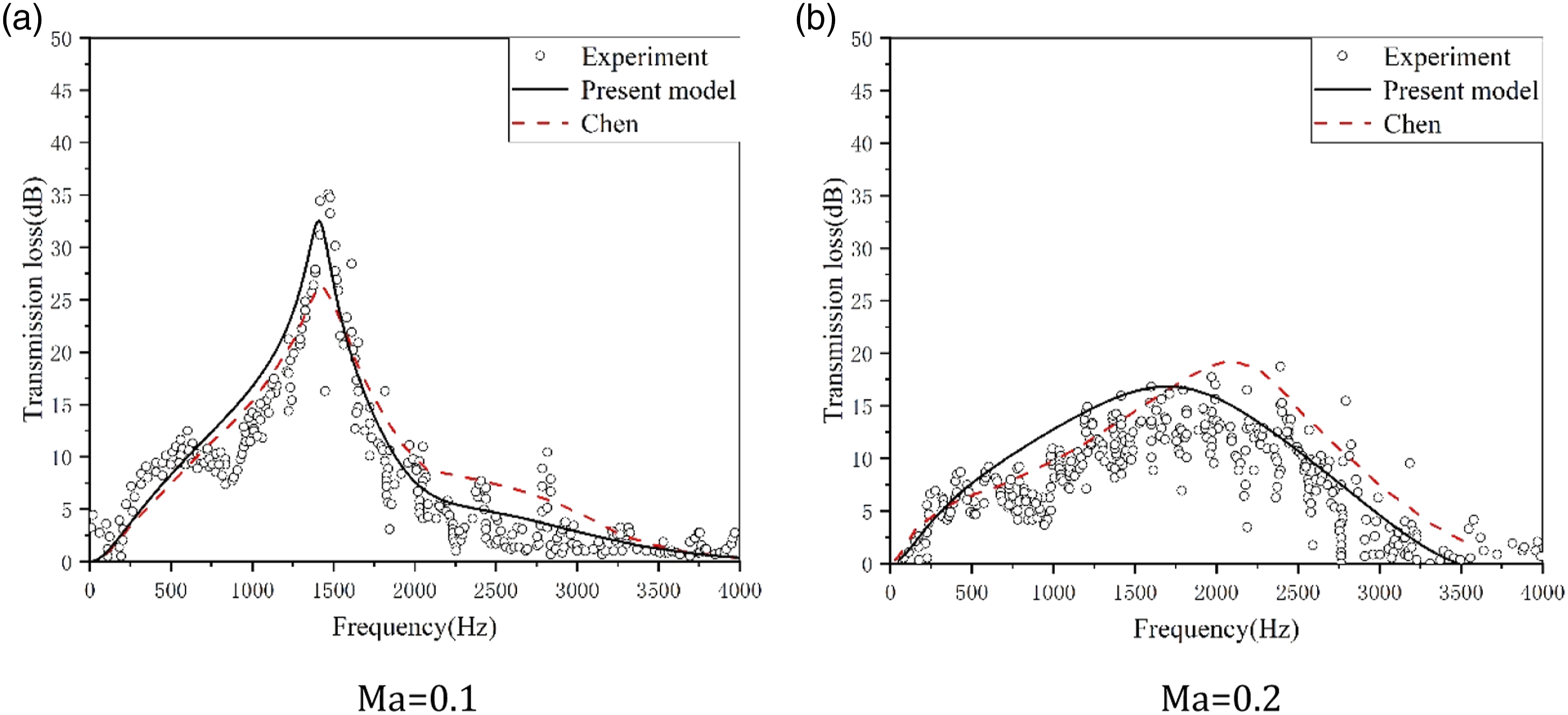
Effect of perforation angle on transmission loss
According to Zhao,
42
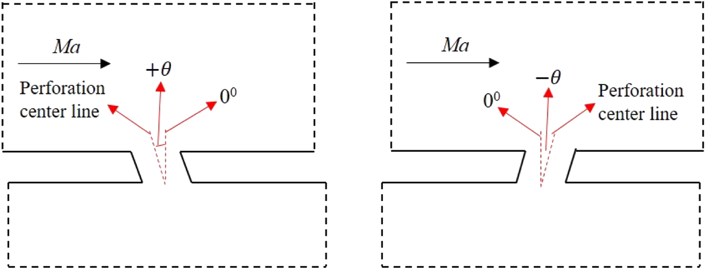
it was found that the geometry of the perforation has a non-negligible effect on the acoustic performance of perforated plates in the flow state. This paper will extend to the effect of perforation angle on the acoustic impedance of perforations under the action of swept flow. The perforation angle is defined as the angle between the central axis of the perforation and the vertical direction, As shown in Figure 12, the tilt of the axis upward is denoted as ‘+θ’, and the tilt of the axis downward is denoted as ‘– θ’. The effect of the perforation angle on the acoustic resistance R0o and acoustic reactance X0o of the vertical perforation (0°) is investigated by numerical calculations at different grazing flow Mach numbers Ma Perforation angle model diagram.

Effect of perforation angle on transmission loss at different Ma
The size of the muffler model used in this section is l = 50 mm, D = 90 mm, dh = 3 mm, tp = 3 mm, φ = 12% and Ma = 0.05, 0.1, 0.2. To study the flow characteristics of the keyhole at different perforation angles, the distribution of turbulent viscosity in the y direction is studied at the line segment CD of the lower surface of the keyhole. Figure 13 shows the turbulent viscosity of the transverse line at the centre of the perforation outlet at different perforation angles when the Mach number is 0.1. The abscissa is the average distribution point in the y direction from the inner wall near the incoming flow direction as the starting point (point C) to the endpoint (D). As shown in Figure 13, the larger the angle of inclination from upstream to downstream, the more the turbulent viscosity profile expands towards the inner wall in the incoming direction, and the stronger the spread of turbulent vortex clusters, and the expansion becomes more pronounced as the Mach number increases, indicating that the angle of inclination to the downstream under the effect of the swept flow will enhance the sound perturbation effect of the flow, which may lead to the deterioration of the muffler’s muffling performance. Turbulent viscosity distribution.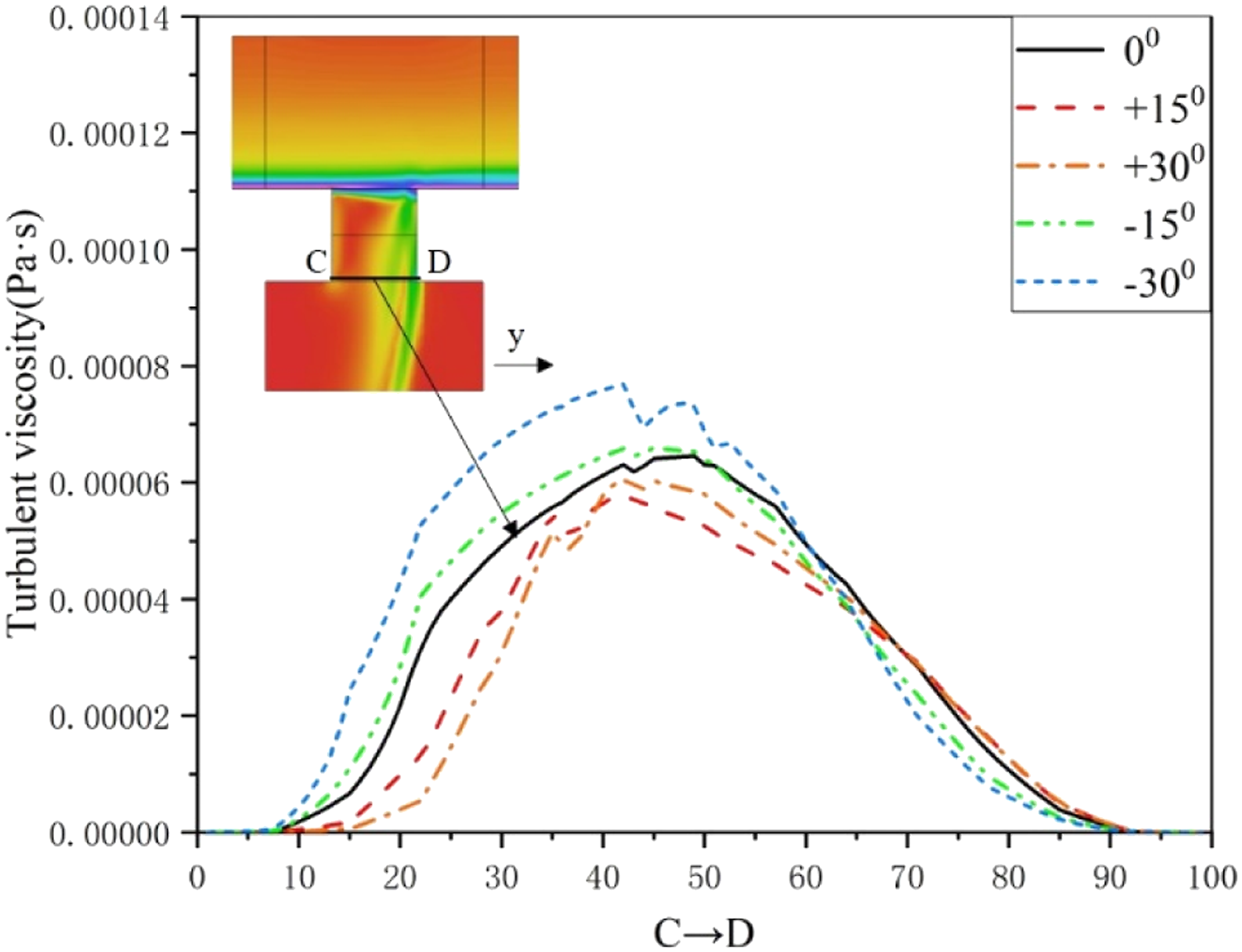
Figure 14 shows the effect of perforation angle on acoustic impedance at different Mach numbers. It can be seen from the figure that the dimensionless acoustics resistance r0 is positive when the perforation angle is tilted downstream, and the positive value becomes larger as St and Mach number increase, indicating that the angle tilted upstream enhances the acoustics resistance r0, resulting in enhanced sound absorption performance of the perforated plate; The dimensionless acoustics reactance x0 is positive and increases as St rises, indicating that the angle of inclination upstream will weaken the acoustics reactance x0, resulting in more sound energy being radiated by the perforated plate. When the perforation angle is tilted upstream, the dimensionless acoustics resistance r0 is negative and increases with St and Mach number, indicating that the angle tilted downstream weakens the acoustics resistance r0 and leads to a weakening of the perforated panel’s sound absorption performance; The dimensionless acoustics reactance x0 is positive and increases as St rises, indicating that the angle of inclination downstream will enhance the acoustics resistance x0, resulting in more sound energy being radiated by the perforated plate. Overall, the degree of variation of the dimensionless acoustics reactance x0 is greater than the dimensionless sound resistance r0, which may lead to the acoustics reactance x0 being the main factor in the variation of perforated plate acoustic properties due to the angle of perforation. Effect of perforation angle on acoustic impedance at different Mach numbers. (a) Ma = 0.05; (b) Ma = 0.10; (c) Ma = 0.20.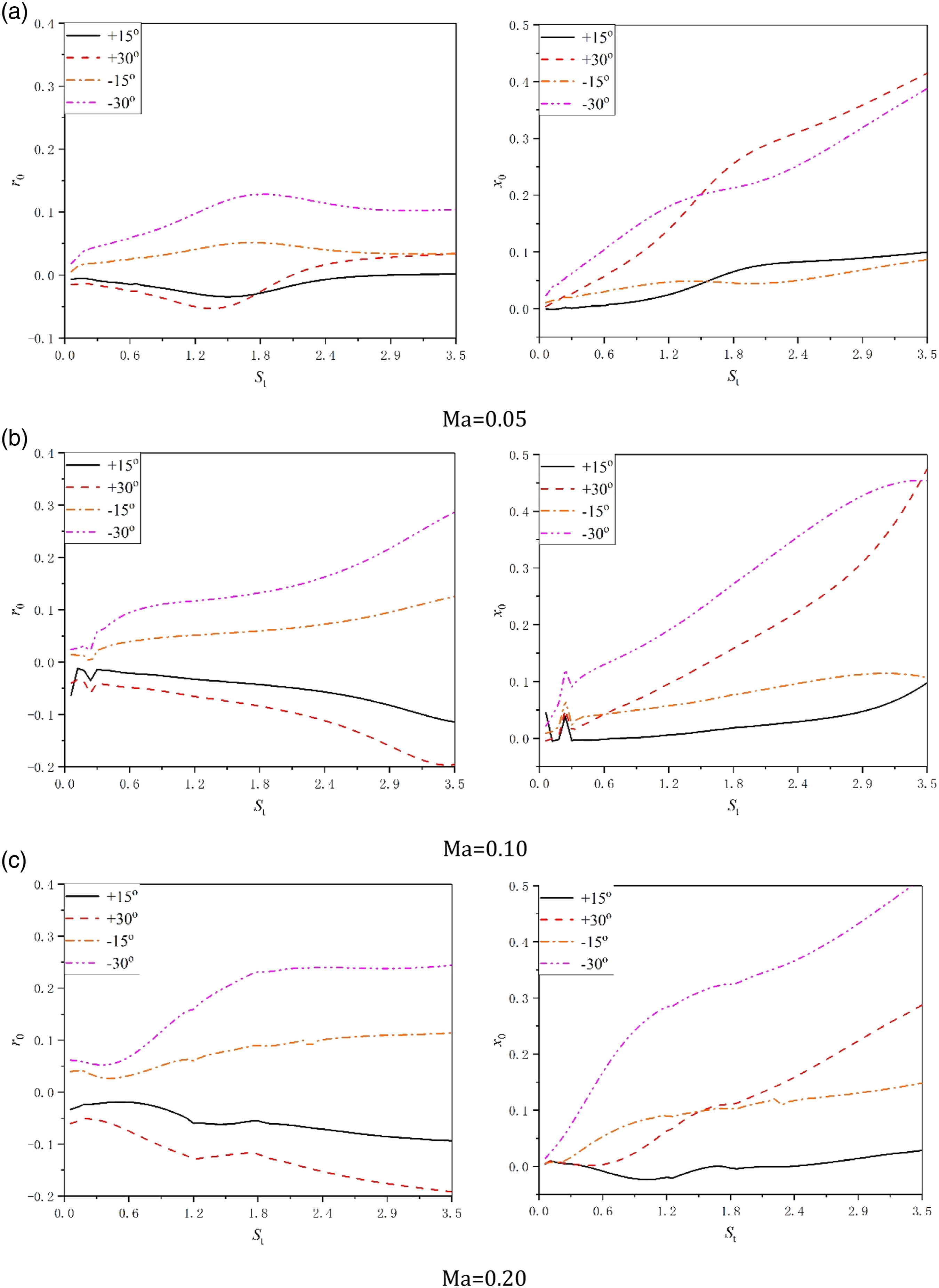
Figure 15 shows the transmission loss comparison of each perforation angle at different Mach numbers. As shown in the figure, when the Mach number is 0.05, the larger the perforation angle, the higher the offset of the resonant frequency of the muffler to the lower frequency, and as the Mach number increases, the offset of the perforation angle tilted downstream is gradually larger than that tilted downstream, while the peak value of the transmission loss tilted upstream is obviously larger than that corresponding to the peak value tilted downstream, mainly because the tilted angle increases the equivalent thickness of the perforated plate and the effect of the grazing flow The angle of inclination to the downstream will enhance the perturbing effect of the flow on the sound, enhancing the acoustics reactance value and weakening the muffling performance of the muffler, which is in line with the description in Figure 14. As the Mach number increases, the effect of the perforation angle on the transmission loss is limited, mainly because the structural micro-variations at high flow rates affect the anechoic performance to a limited extent and the transmission loss curve becomes increasingly smoother. Effect of perforation angle on transmission loss at different Mach numbers. (a) Ma = 0.05; (b) Ma = 0.1; (c) Ma = 0.20.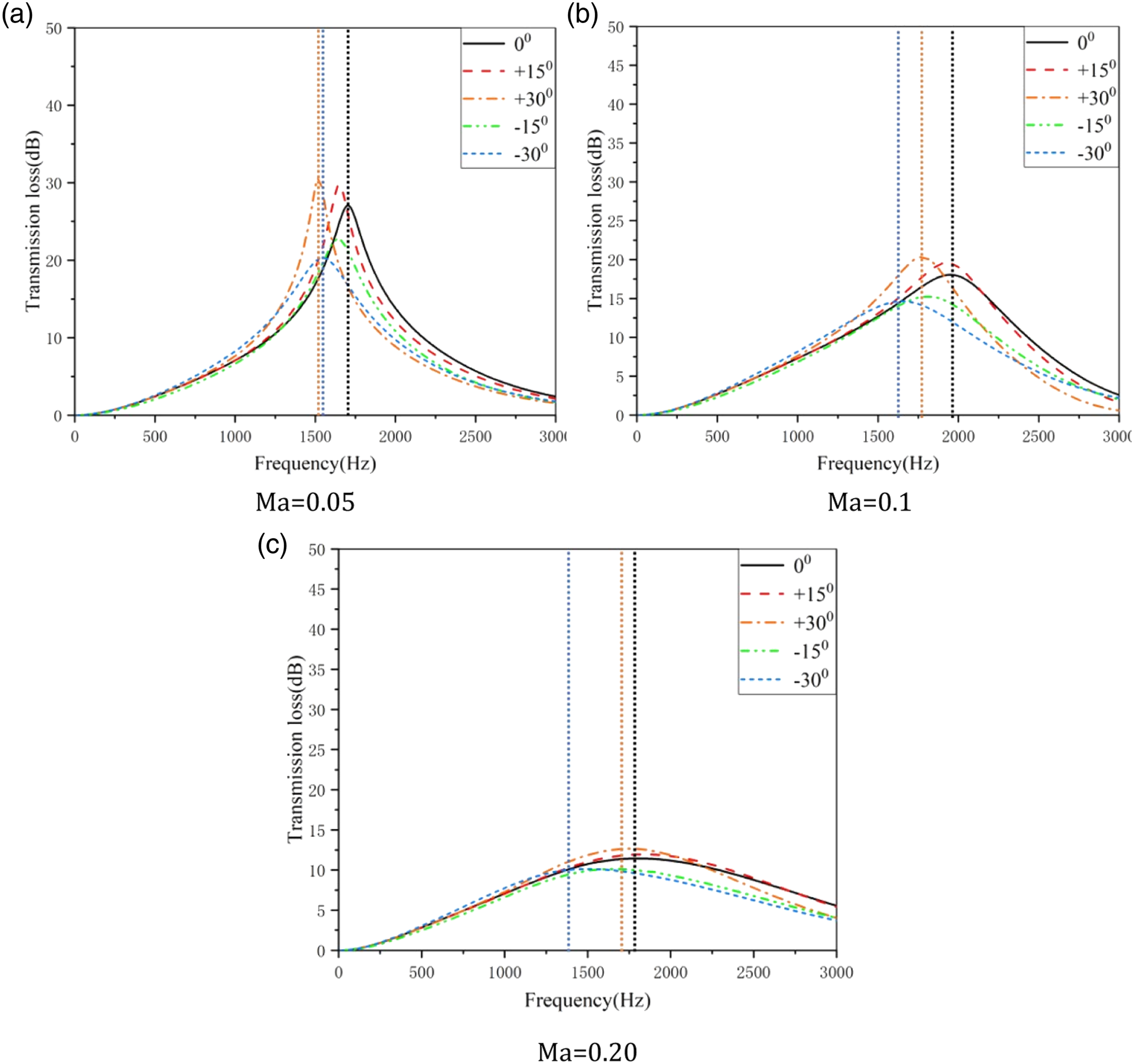
Effect of perforation angle on transmission loss at different dh/tp
The model used is a muffler with length l = 50 mm, diameter D = 90 mm, perforation rate φ = 12%, Mach number Ma = 0.1 and aperture plate thickness ratios of dh/tp = 1, 1.5, 2 and 3. The main reason for not considering the scheme of dh/tp>2 is that the structural characteristics of perforation angle cannot be highlighted. Figure 16 shows the effect law of perforation angle on acoustic impedance when the aperture plate thickness ratio is 2. As can be seen from the figure, when St is small, the variation of dimensionless sound resistance and sound resistance is not great. When St = 2.9, the dimensionless acoustics resistance r0 and acoustics reactance x0 will show a trough and crest variation, which will cause the muffler’s muffling performance to deteriorate at high frequencies. The effect of perforation angle on acoustic impedance for an aperture plate thickness ratio of two.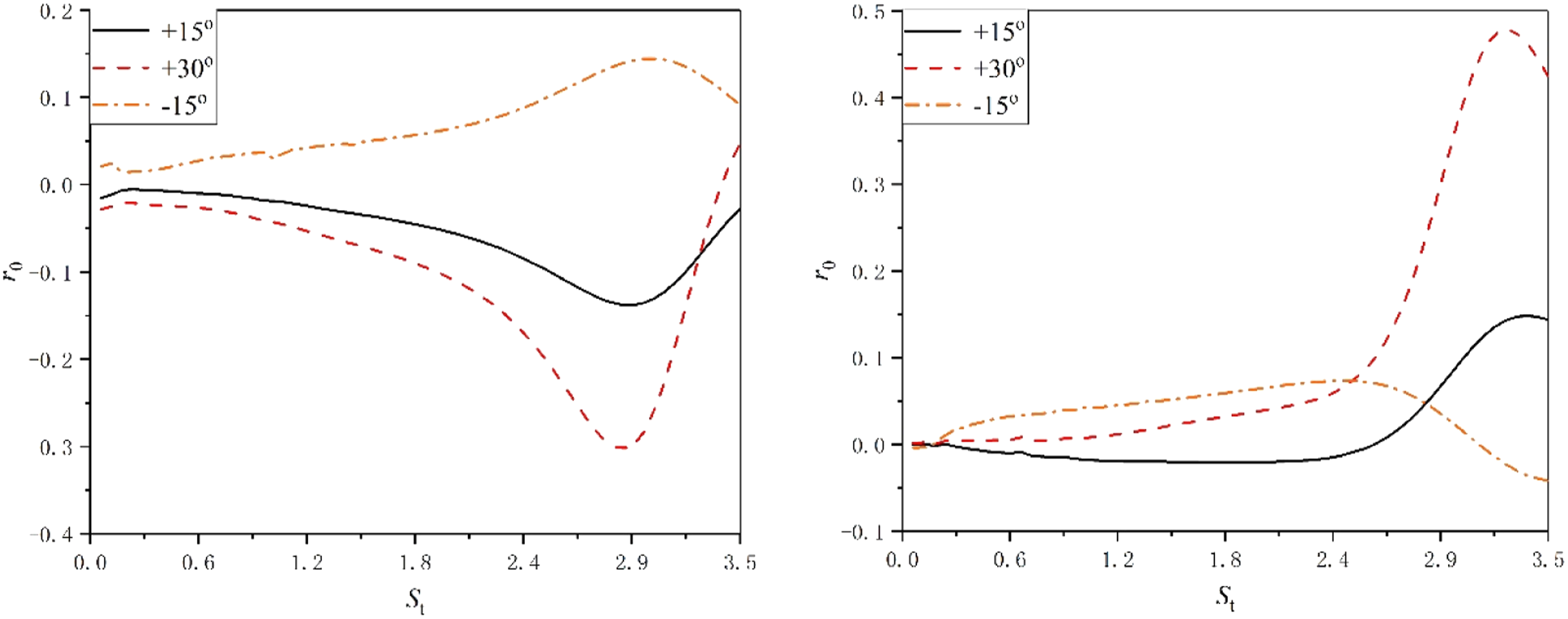
As shown in the Figure 17, when dh/tp = 1 and 1.5, the effect of the perforation angle on the transmission loss of the muffler is more obvious, and the angle of the upstream tilt will still enhance the peak value of the resonance frequency. However, when dh/tp = 2, the existence of the perforation angle weakens the muffler performance, and the larger the perforation angle, the more obvious the weakening, this coincides with the depiction in Figure 16. Effect of perforation angle on transmission loss at different aperture plate thickness ratios. (a) dh/tp = 1; (b) dh/tp = 1.5; (c) dh/tp = 2.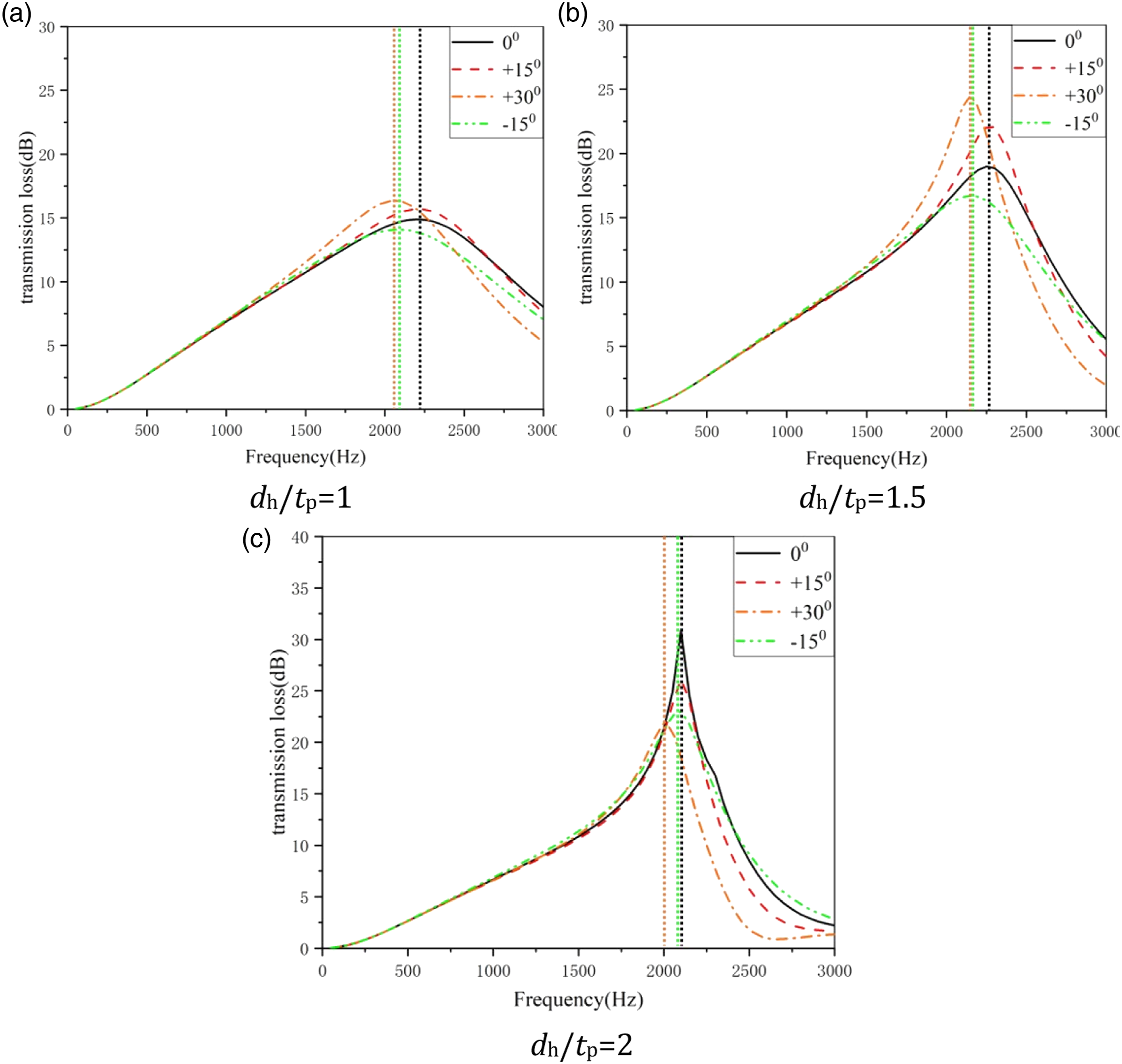
Discussion and conclusions
The purpose of this work is to obtain the accurate acoustic impedance of the perforated plate under grazing flow, to calculate the transmission loss of the muffler, and to investigate the effect of the perforation angle on the transmission loss of the muffler under different Mach number (Ma) and aperture plate thickness ratio (dh/tp). The main conclusions of the study are as follows: 1. The perforated plate acoustic impedance is extracted by defining the perforated plate inlet and outlet sound pressure and the volume velocity in the hole, respectively, in the frequency domain linear Navier–Stokes equation. The extracted perforated acoustic impedance is defined in the framework of the finite element method to calculate the transmission loss of the perforated muffler, and the calculation method has a high prediction accuracy in most cases by comparison with experimental data. 2. The presence of the perforation angle disguisedly increases the equivalent thickness of the perforated plate and acoustics reactance, shifting the resonant frequency of the muffler towards lower frequencies. Under grazing flow, when 0<Ma≤2, the peak value of the transmission loss tilted upstream is greater than that tilted downstream with vertical perforation, while the angle of perforation tilted downstream enhances the perturbation effect of flow on acoustics, leading to an increase in sound reactance and a decrease in the muffler’s muffling performance. When Ma>2, the presence of perforation angle has less effect on the transmission loss. 3. Under grazing flow, when 1≤dh/tp<2, the angle of inclination upstream still has a relatively positive effect on the transmission loss, but when dh/tp ≥2, the presence of the perforation angle weakens the muffler’s muffling performance, and the larger the perforation angle, the more obvious the weakening.
Footnotes
Declaration of conflicting interests
The author(s) declared no potential conflicts of interest with respect to the research, authorship, and/or publication of this article.
Funding
The author(s) received no financial support for the research, authorship, and/or publication of this article.