
Abstract
With the development of machinery toward high speed, high power, and high reliability, the vibration and noise problems of gearboxes become more prominent. The vibro-acoustic characteristics of gear-rotor-bearing coupled system are difficult to be characterized by the simple gear transmission system. This paper concentrated on modeling an improved dynamic model of gear-rotor-bearing system under multi-source excitation. The initial bending of shaft, precession effect, and gear eccentricity were included in the model to calculate the dynamic response. An extended computational method for predicting the radiation noise of a gearbox was developed. The distribution of the sound pressure around the gearbox was obtained by combining the finite element vibration analysis and boundary element noise analysis. Experimental vibration and noise measurements from a simplified gearbox confirmed the simulation results. The influences of precession effect on dynamic response and radiated noise of the gearbox were investigated. Results show that with the increase of input speed, the peak speeds of the system dynamic load increase and the resonance region shifts. The resonance regions of each field point of the gearbox are enlarged, and the noise is enhanced obviously. The results provide a theoretical basis for the further development of high-quality silent gearboxes.
Introduction
Gearboxes are one of the main components of various mechanical equipment. The forces generated at the gear meshing are transmitted through shafts and bearings to the housing, which excites the housing to radiate noise. Due to manufacturing and assembly errors, the initial bending of shaft, mass imbalance, and gear eccentricity occur inevitably in the actual gearbox. To design low-noise gearboxes, an improved computational method for precisely analyzing the vibration and noise of the gear-rotor-bearing coupled system is needed.
Previous studies have yielded a variety of models for the geared rotor system dynamics. A large number of experiments and numerical simulations were carried out on the dynamic characteristics. In earlier studies, Kahraman et al. 1 firstly used the finite element method to analyze the dynamic characteristics of the spur gear coupled rotor system, and established a bending-torsional coupled dynamic model considering the elastic contact of the gear. Under the assumption of various vibration conditions, the unbalanced response and gear eccentricity error response of the rotor system were analyzed. Similarly, Neriya et al. 2 also used the same method to study the bending-torsional coupled vibration of the rotor in a geared rotor system. Kubur et al. 3 discretized the gear shaft into multiple flexible elements, introduced the axial translation degree of freedom of the gear to establish the dynamic model of the multi-stage helical gear transmission system, and analyzed the influence of shaft dimensions and shaft angles on the dynamic transmission error. For the geared rotor system, the dynamic characteristics are very complex and the factors are various.4–11 Among them, shaft bending,8,9 gear eccentricity,10,11 and mass imbalance 12 are important factors for the geared rotor system. Subsequently, Yuan et al. 13 proposed a dynamic model of a wide-faced gear-rotor system based on nonlinear contact algorithm, which takes into account the mesh misalignment caused by shaft deflection. Kong 14 established geared rotor system model with and without housing by the finite element method and illustrated that the housing flexibility reduces the natural frequencies and the amplitudes of the resonance peaks. Zhao 15 proposed an improved loaded tooth contact analysis method considering geometric eccentricity and discussed the dynamic characteristics under different initial eccentric phase.
In the early research on gear noise, many empirical formulas for estimating noise intensity were obtained through experiments.16–18 However, the shape of the housing is one of the main factors in the radiated noise of the gearbox, so these empirical formulas may not be suitable for other gearboxes because the radiated noise is strongly dependent on the shape of the housing. Subsequently, the vibration and noise of gearbox is mainly studied by numerical simulation, among which the finite element method/boundary element method (FEM/BEM) is the most widely used. Abbes et al. 19 established a three-dimensional finite element model considering the influence of the fluid inside the gearbox housing and calculated the radiated structure-borne noise from a gearbox by the Rayleigh integral method. Later, Theodossiades et al. 20 presented an analytical methodology that can predict the airborne noise level and dynamic behavior of gear pairs under different operating conditions. Guo et al. 21 proposed a computational process to predict radiation noise of the gearbox based on the finite element model and lumped parameter model, and analyzed the influence of housing flexibility on bearing load and radiation noise. Zhao et al.22,23 investigated the damping performances of perforated liners with different open area ratios. It was found that the double-layer liner is more effective on damping acoustic noise in terms of increased global maximum power absorption and effective frequency ranges. Then, Chen et al. 24 developed a simulation method combining the coupled dynamics model of the gear system and the acoustic finite element model of the housing for predicting the noise of the reducer. The effects of pressure angle and helical angle on dynamic behavior and radiated noise under the rated working condition were investigated. Wang et al. 25 proposed an improved calculation method to predict the vibration and noise of the gearbox, and found that after considering the flexibility of the shaft, the fluctuation amplitude of the dynamic load of the bearing was reduced and the main resonance mode of the gearbox changed. Han et al. 26 established a nonlinear dynamic model of a gearbox considering time-varying friction and dynamic backlash, and discussed the effects of meshing excitation on vibration and noise of the gearbox.
Previous studies establish a simple gear system model to calculate the radiation noise of the gearbox. However, the vibration characteristics of a gear-rotor-bearing coupled system are much more complex than that of the simple gear system. On the one hand, there are complex coupled bending and torsional vibrations between the shafts of the system. On the other hand, the precession effect and geometric eccentricity have obvious effects on the vibration and noise of the gearbox under high-speed conditions. Most of the literature mainly focuses on the dynamic characteristics of the geared rotor system. Few studies are interested in the influence of multi-source excitation on vibration and radiation noise of the gear-rotor-bearing coupled system under high-speed conditions, such as the geometric eccentricity, initial bending, and precession effect.
The objective of this study is to develop an extended computational method for the prediction of the vibration and radiation noise of a gearbox. As the focus is not only on the effects of the transmission error but also on the effects of multi-source excitation. Firstly, considering the transmission error, initial bending, geometric eccentricity, and precession effect, an improved dynamic model of the gear-rotor-bearing coupled system was established. Then, the vibration and radiation noise of a two-stage gearbox was simulated by combining finite element vibration analysis and acoustic boundary element noise analysis. Furthermore, experimental measurements are used to validate the numerical predictions. Finally, the effects of precession on the vibration and radiation noise of the gearbox are systematically discussed.
Gearbox vibro-acoustic propagation analysis
Gearbox parameters and method
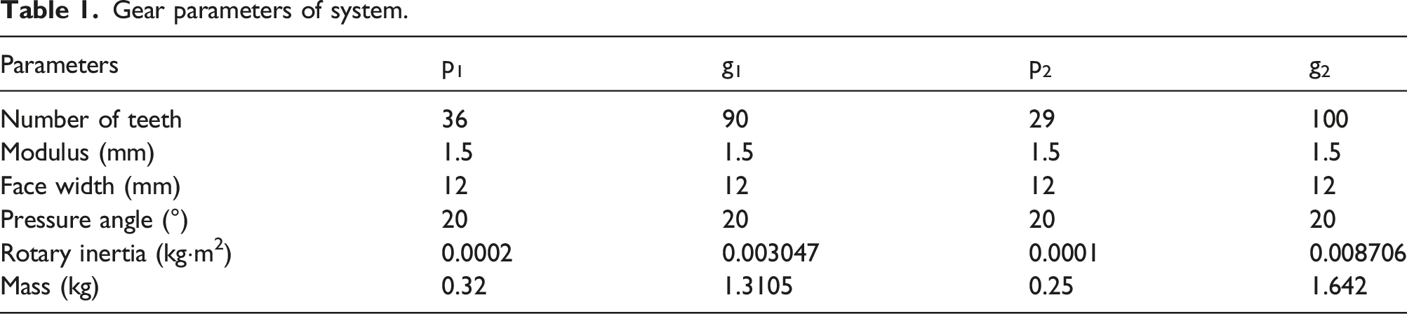
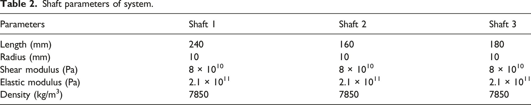
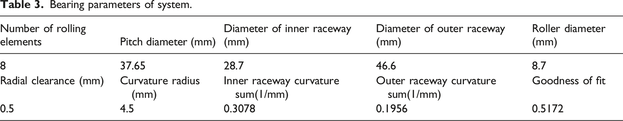
Take the two-stage three-parallel shaft gearbox of the wind turbine gear transmission test bench produced by SQI Company as an example for vibration and noise analysis, and its internal and external structures are shown in Figure 1. The gearbox consists of three shafts, two pairs of spur gears, six deep groove ball bearings, and a housing. The first-stage gear transmission is high-speed gear transmission, and the second-stage gear transmission is low-speed gear transmission. Shaft 1, shaft 2, and shaft 3 are the input shaft, the intermediate shaft, and the output shaft, respectively. According to the test bench instructions and the measurement of the gearbox, the gear parameters, shaft parameters, and bearing parameters of the system are listed in Table 1, Table 2, and Table 3. Two-stage gearbox. (a) Outside and (b) inside of the gearbox from real photos. Gear parameters of system. Shaft parameters of system. Bearing parameters of system.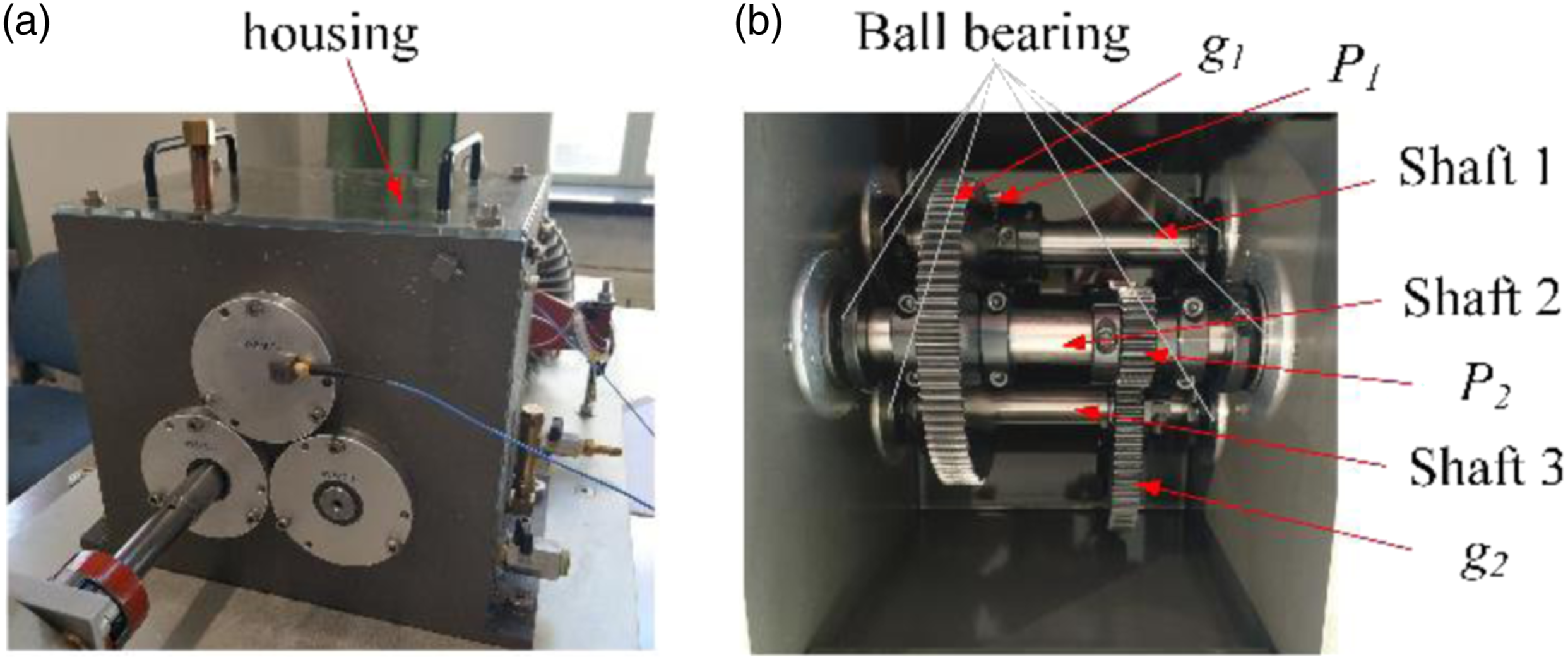
The flow chart of the extended computational method for the prediction of radiation noise of a gearbox is shown in Figure 2. First, a coupled dynamic model of the geared rotor system is established by using the finite element method. The time-varying stiffness, geometric eccentricity, initial bending, and precession effect are considered. The dynamic model of the geared rotor system is verified and corrected by experiments. The dynamic load of the bearing and the natural characteristics of the geared rotor system are obtained by solving the dynamic model. Second, according to the assembly relationship of the gearbox, the boundary conditions are applied to the finite element model of the housing, and the structural mode of the housing is extracted. Then, the dynamic load of each bearing is applied to the corresponding bearing position, and the dynamic response of the gearbox is calculated by the modal superposition method to obtain the surface vibration velocity of the gearbox. The surface elements of the finite element model of the housing are extracted, and the acoustic boundary element model of the housing is established by means of surface patching and mesh coarsening. The fluid properties and sound field characteristics are defined to establish the acoustic transfer vector between the structural vibration and the sound field. Finally, the noise radiation of the gearbox is calculated with the normal velocity as the boundary condition, and the acoustic response of each field point of the gearbox is obtained. The computational process of noise radiation from gearbox.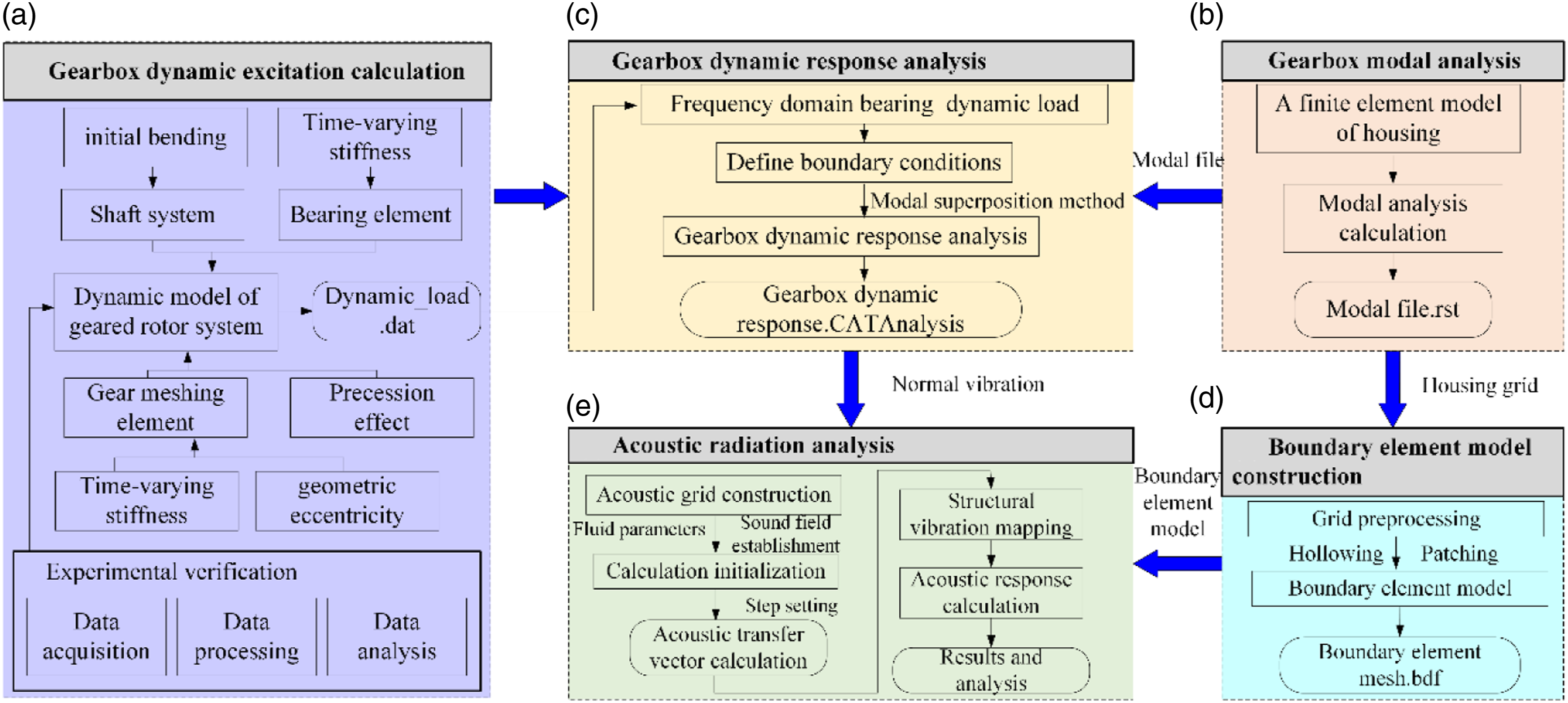
Model of the geared rotor system
Model of shafts system
The three shafts of the shafts system are, respectively, divided into 12 shaft elements, 8 shaft elements, and 9 shaft elements, as shown in Figure 3. There are two common beam elements, Euler–Bernoulli beam element and Timoshenko beam element. In order to better simulate the dynamic characteristics of the geared rotor system, the shafts are modeled using the Timoshenko beam element with six degrees of freedom. Model of the shafts system.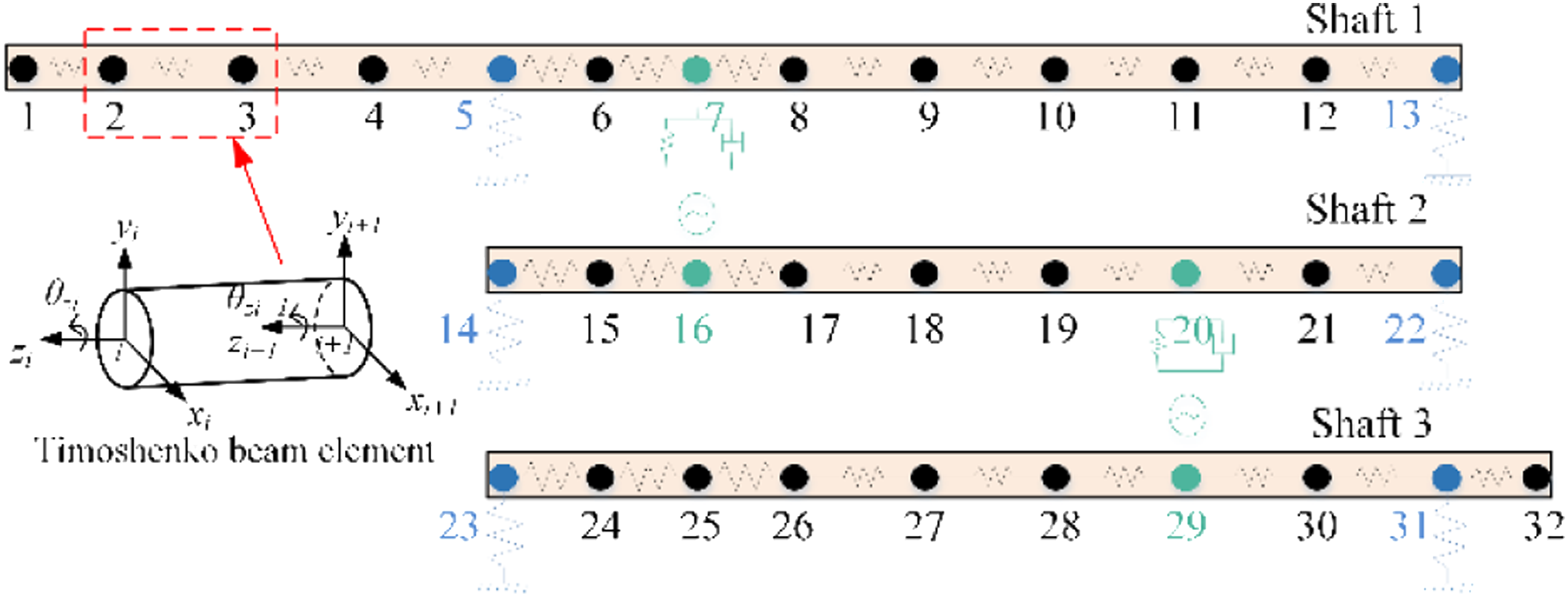
The generalized displacement vector of the ith shaft element is defined as
The stiffness and mass matrices of each shaft element are determined and assembled to form stiffness matrix 

Due to the factors such as uneven material and manufacture error, the shaft has the initial bending. The shaft bending is equivalent to adding an imbalance on the rotor. The bending of the shaft element varies with the position. The first-order mode shape of the geared rotor system can be used to characterize the bending of the shaft. Ignoring the influence of rotation angle, the first-order mode shape of the geared rotor system is
The initial bending of the shaft can be given as
The initial bending force vector of the shaft is given as


When the geared rotor rotates at angular velocity Whirl diagram of the geared rotor system.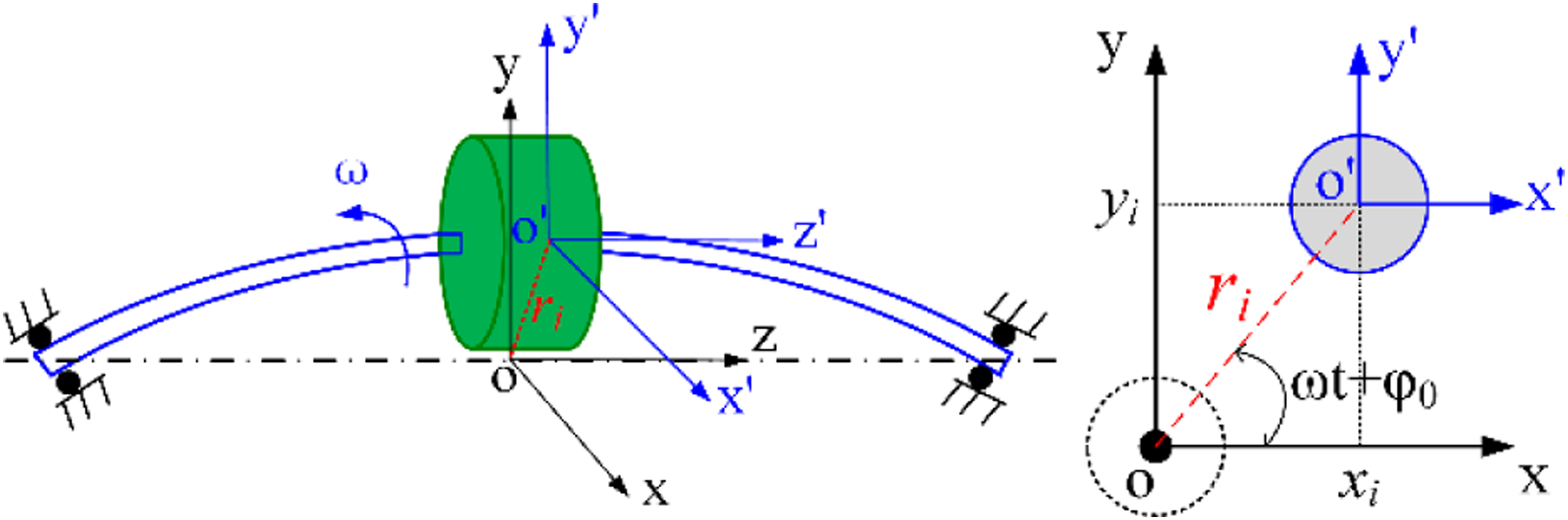
The mass unbalance force acting on the rotor system element is given as
The generalized displacement vector generated by precession of each element of the rotor system is given as
The precession matrix is given as
The mass unbalance force of each element is given as
Model of gear pair with the geometric eccentricity
Considering the geometric eccentricity of the spur gear pair, the three-dimensional dynamic model of the gear pair is shown in Figure 5. Op, Og are the rotation centers of the pinion and the gear. Op’, Og’ are the geometric centers of the pinion and the gear. Op”, Og” are the mass centers of the pinion and the gear. ep, eg are the eccentricity of the pinion and the gear. kpg, cpg, epg denote the time-varying mesh stiffness, mesh damping, mesh error of gear meshing element, respectively. xp, yp, xg, yg are the translational degrees of freedom of the pinion and the gear, respectively. θzp and θzg are the rotational angles degrees of freedom of the pinion and the gear, respectively. Dynamic model of a spur gear pair (a) Three-dimensional model (b) Axial projection.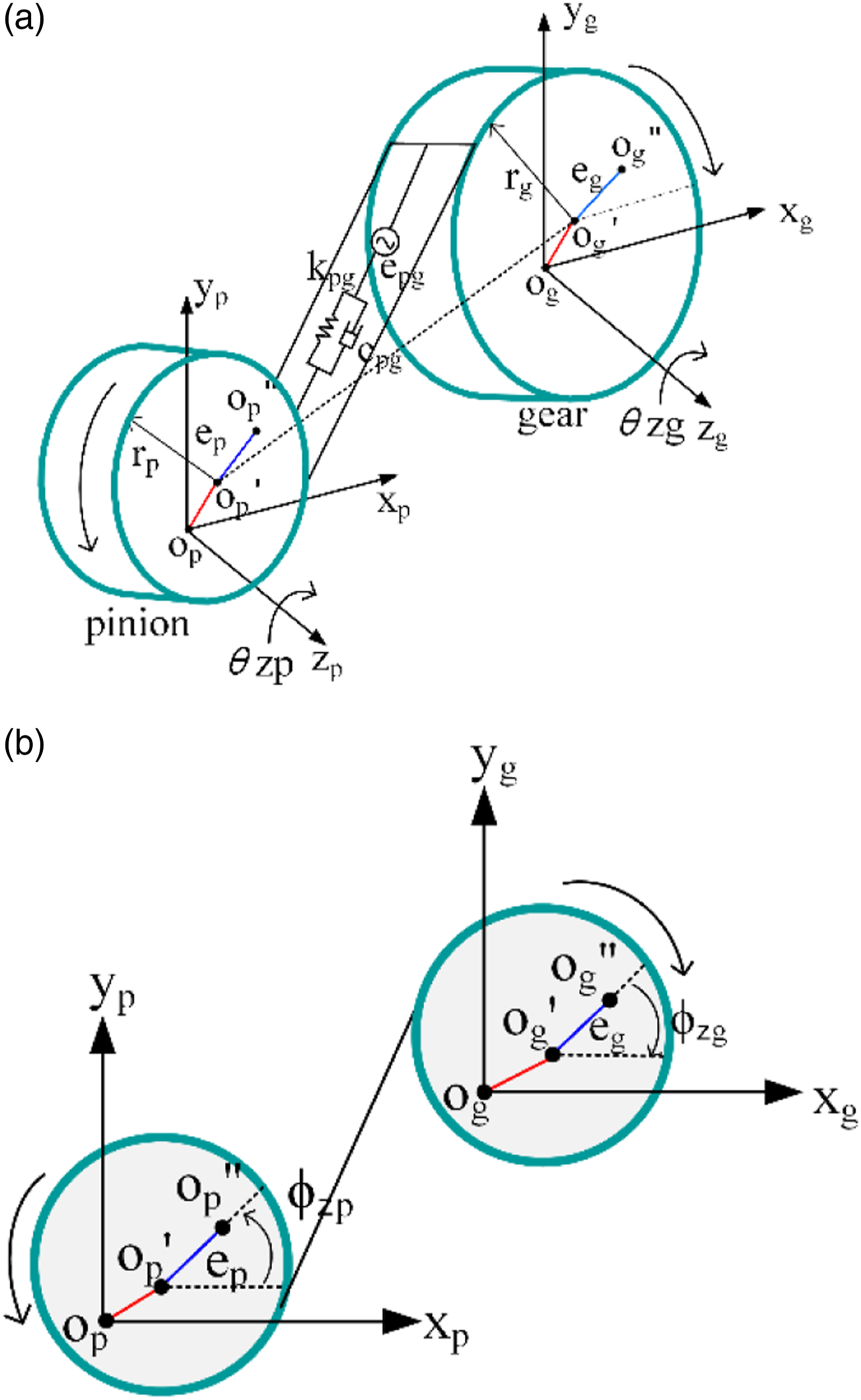
The generalized coordinate vector of the mass center of the gear pair is defined as
The displacement relation between the mass center and rotation center is derived as follows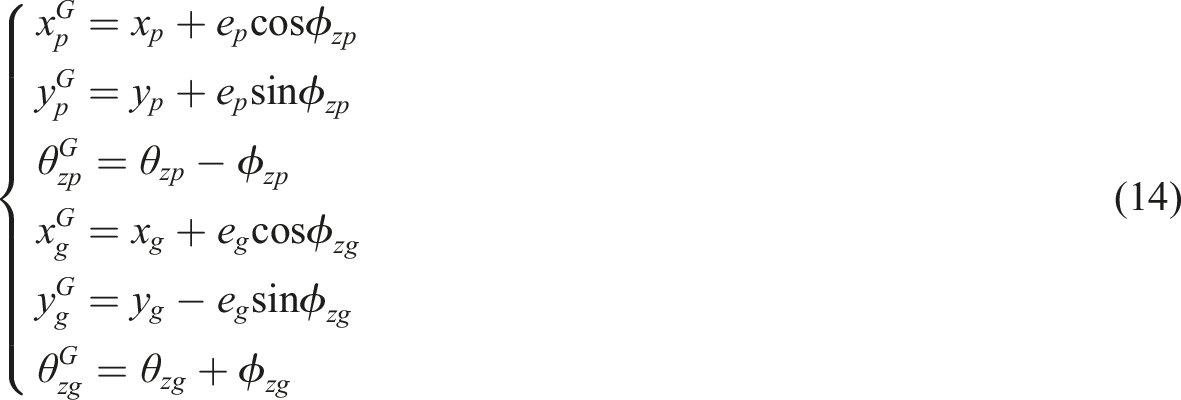
The relative displacement of the pinion and gear along normal line of action can be given as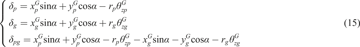
Introducing the time-varying mesh stiffness, the motion equation of the gear mesh element can be written as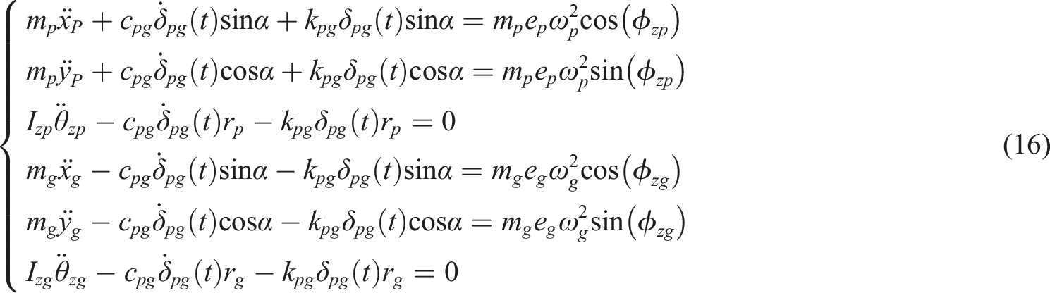
The matrix form of the motion equation of gear mesh element can be written as
Model of bearing
The shafts and the housing are connected by six bearings. The bearing inner ring and outer ring realize load transfer through rollers. Due to elastic contact deformation, the change of bearing load leads to dynamic fluctuation of displacement. Figure 6 shows the model of deep groove ball bearing and two situations of the bearing. Model of the bearing.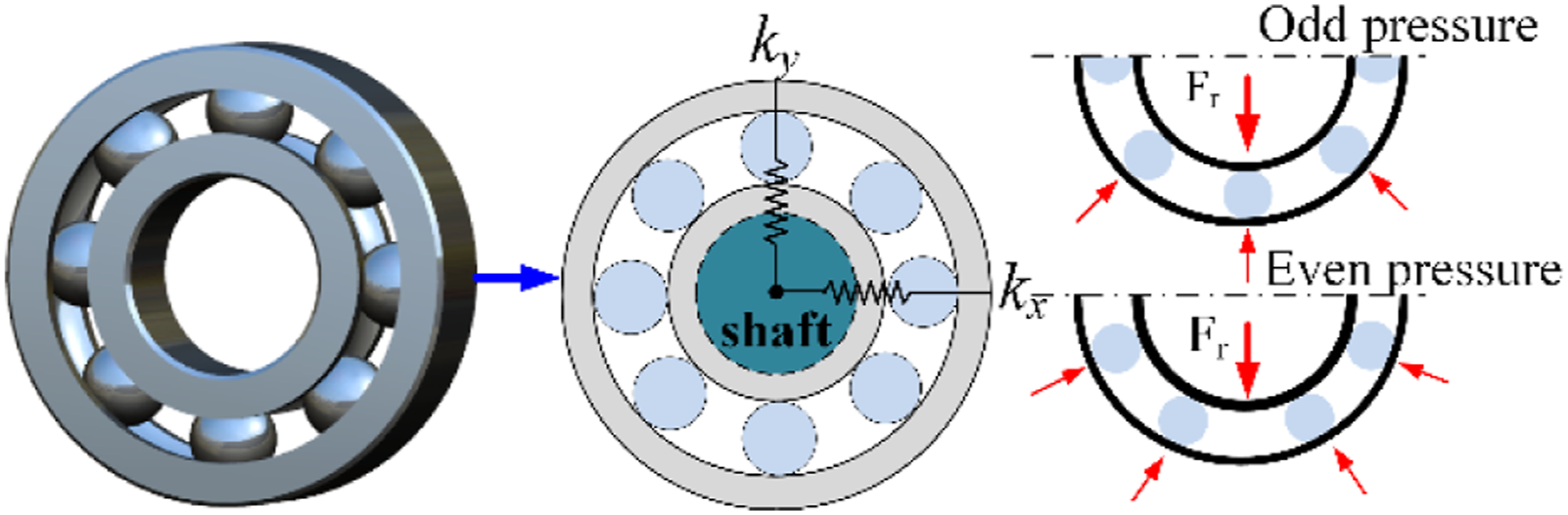
The radial displacement can be given as
The stiffness of bearing is given as
The time-varying bearing stiffness is expressed in equation (20)
Model of the geared rotor system
When the dynamic model of each element is well defined, the overall model of the geared rotor system can be determined through assembling the element dynamic models, as shown in Figure 7. Schematic diagram of overall system stiffness.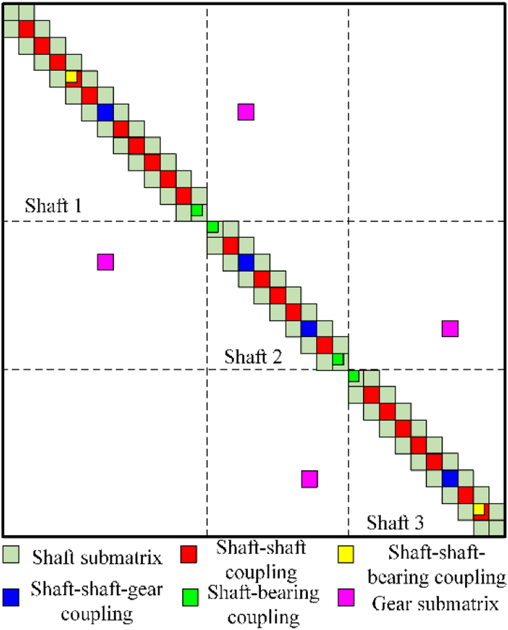
The matrix form of motion equations of the overall system can be written as
Dynamic experiment
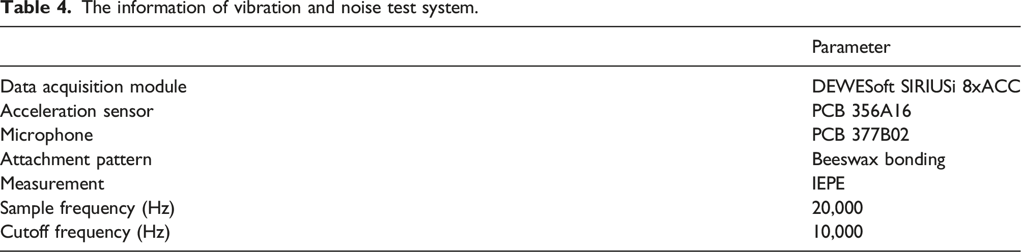
The wind turbine gear transmission test bench produced by SQI company is used to validate the mathematical model and vibration response, as shown in the Figure 8(a). The test bench is mainly composed of drive motor, controller, two-stage spur gearbox, and magnetic powder brake. The two-stage spur gearbox is driven by the drive motor. The controller controls the start and stop of the motor and displays the input speed in real time. The magnetic powder brake provides the load torque for the gear transmission system. The DEWEsoft data acquisition system was used to collect and analyze the vibration signal, as shown in the Figure 8(c). The detailed information of the experimental system is shown in Table 4. There are two kinds of first-stage pinions, a good gear and an eccentric gear, as shown in the Figure 8(d). The acceleration sensors and microphone used for measurement are shown in Figure 8(e) and (f). The acceleration sensor is used to measure the acceleration signal at the end cover of the gearbox bearing, and the installation position of the sensor is shown in the Figure 8(b). The sampling frequency is set to 20,000 Hz. Eccentricity of gears is inevitable due to manufacturing and assembly errors. The eccentricity of the first-stage pinion in the experiment is 100 μm. The SQI wind turbine transmission system test bench. The information of vibration and noise test system.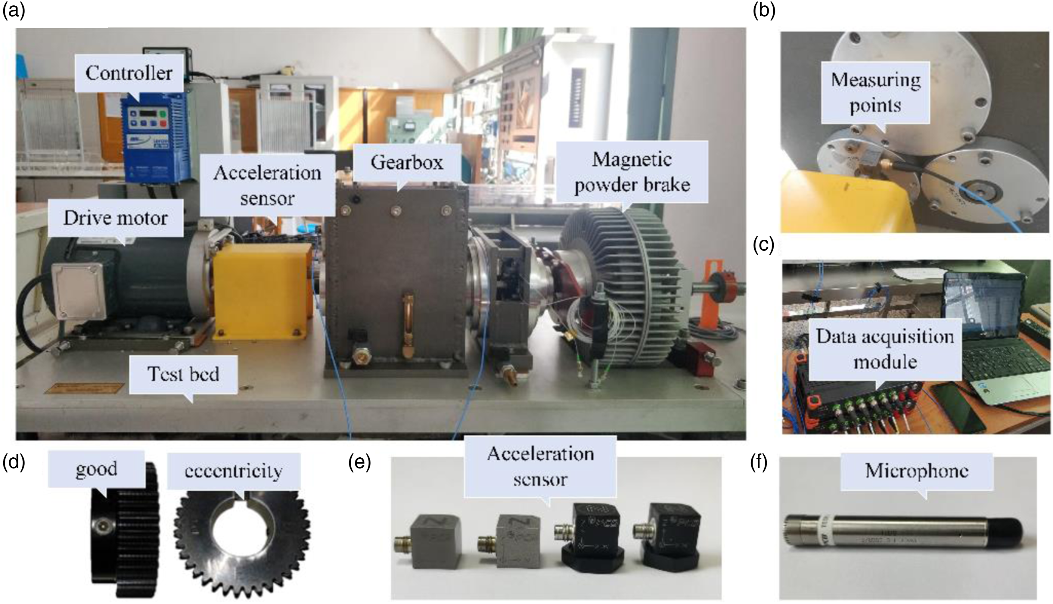
The speed of the input shaft increases in increments of 60 r/min, and the root-mean-square (RMS) values of the vibration acceleration signals are obtained under steady conditions. Figure 9 presents the comparison of the simulated and measured RMS values. The simulated results are different from the measured results in amplitude, but the variation trend of vibration response is basically the same, and the speed corresponding to the peak of vibration response is relatively close. Comparison of the simulated and measured results.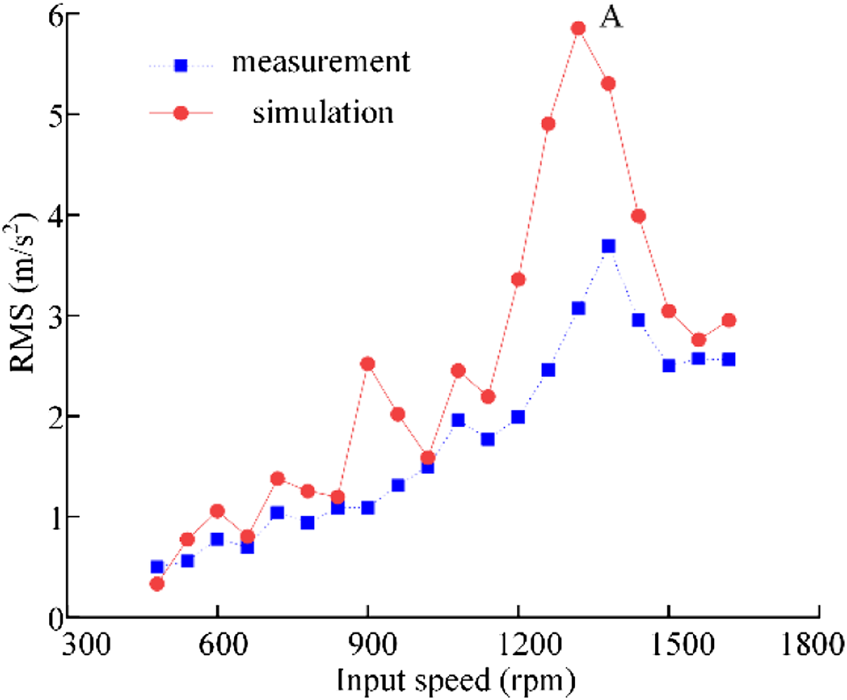
The speed corresponding to point A is 1320 r/min. Since the main excitation frequency components (2fm1) are close to the fourth-order natural frequency (1082.4 Hz) of the gear system, the RMS value increases sharply. The simulated value is slightly larger than the measured value. Analyzing the experimental data, these errors mainly come from: (1) The parameters such as mass, stiffness, damping, and eccentricity in the model are equivalent to the real system, which largely depends on the modeling experience. In particular, the damping parameters such as bending damping, torsional damping, and meshing damping of the system are generally difficult to determine, and there is a certain gap with the real parameters of the system. (2) The simulation ignores the attenuation of acceleration from the bearing to the end cover, and the model ignores the lubricating oil.
However, it is obvious that the two curves both have same variation trend and resonance peaks. The validity of the model is verified by experiments.
Gearbox acoustic analysis and experiment
Due to the correlation between the acoustic boundary element model and the finite element model, a boundary element model of housing is established through patching and regrid on the basis of the finite element model.
In order to improve the computational efficiency, the ATV (Acoustic Transfer Vector) is introduced. The ATV is to establish the correspondence between the sound pressure of the field point and the vibration surface of the structure. If the gearbox structure is changed, only the vibration response of the structure needs to be calculated, and there is no need to recalculate the ATV, which greatly reduces the calculation time. With the gearbox as the center and 1 m as the radius, a hemispherical sound field is established as shown in Figure 10. When calculating, set the speed of sound as 341 m/s, the air density as 1.21 kg/m3, and the step size as 10 Hz. Gearbox field point distribution.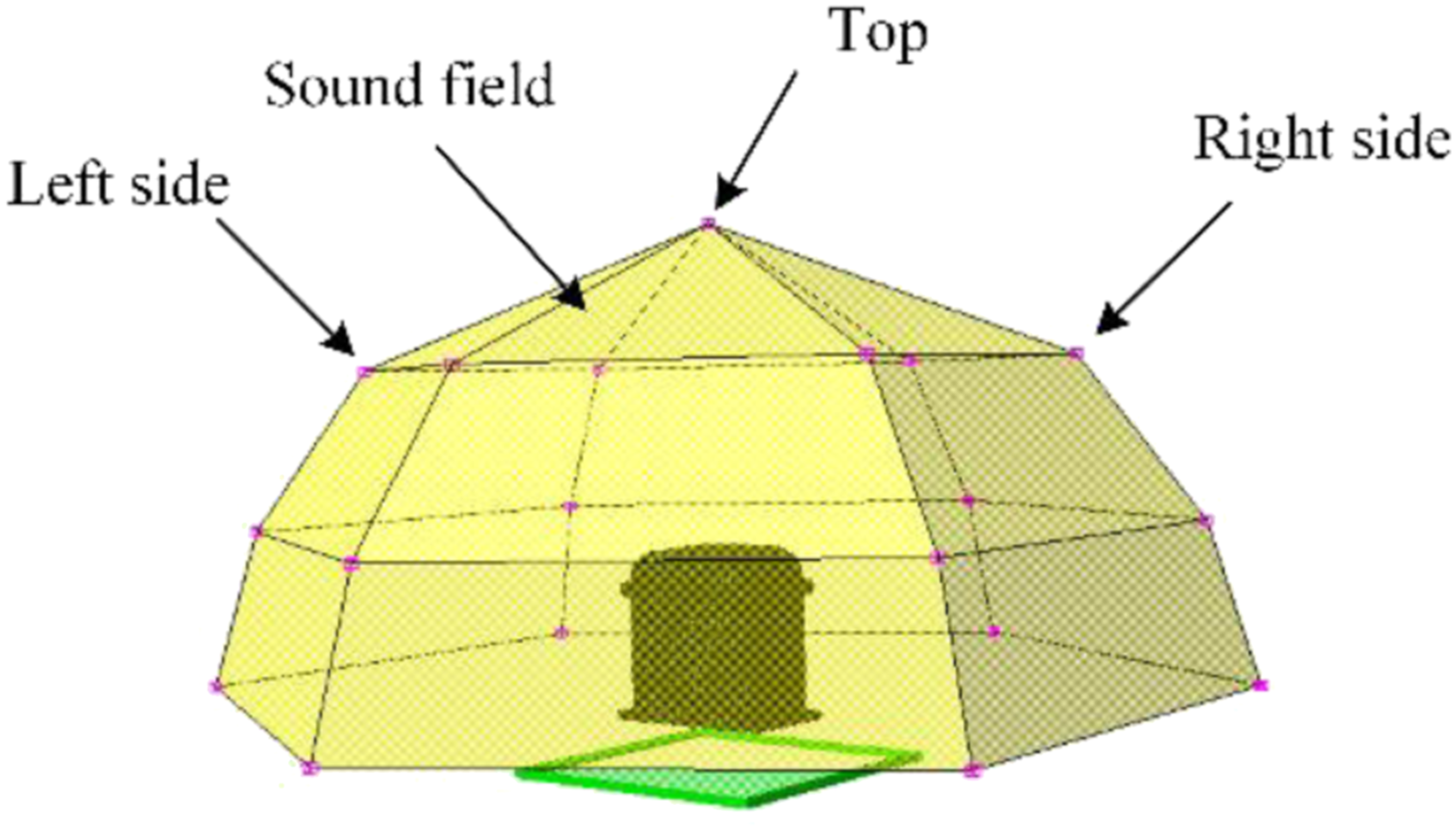
The dynamic loads of bearings are applied to the mass nodes in the center of the bearing holes, and the modal superposition method is used to solve the surface vibration velocity of the gearbox. The surface vibration velocity of gearbox is used as the boundary condition to obtain the field point noise combined with ATV.
An acoustic experiment is performed on the gearbox using the microphone shown in Figure 11(a). Two microphones are, respectively, placed on the left and right sides 1 m away from the gearbox. In the acoustic experiment, the input speed is 1800 r/min. Figure 11(b) shows the comparison of the A-weighted 1/3-octave sound pressure level (SPL) at the field point on the left side of the gearbox. This simulation and the experiment sound pressure levels have similar trends. At low frequency, the experimental sound pressure level is relatively large. This is because the eccentric vibration caused by the manufacturing and installation error of the gearbox is large. In addition, the experimental data are also affected by load noise and other factors, resulting in some other frequency components that cannot be analyzed. There are errors between the simulation results and the experimental results. When the frequency is 500–4000 Hz, the error of simulation and experiment results is relatively small. The validity of the gearbox calculation method is verified by experiments. Any parametric studies can be performed with confidence. (a) Acoustic experiment (b) Comparison of the simulated and measured SPL.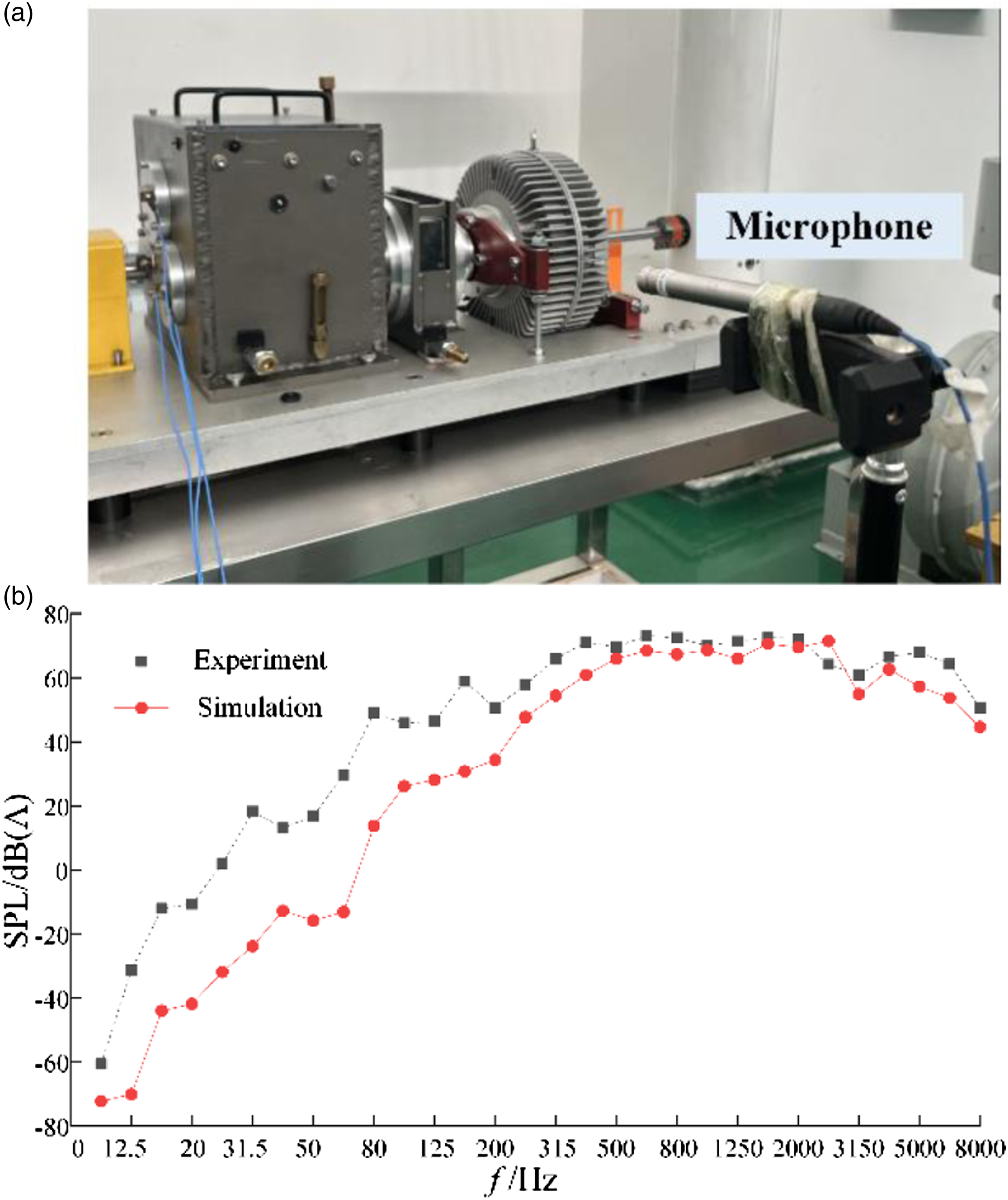
Effect of precession on vibration and radiation noise of gearbox
Natural characteristics of the system
To analyze the influence of the precession on the natural characteristics of the geared rotor system, the Campbell diagram of the geared rotor system is presented in Figure 12. Because of the precession, the natural frequencies of the geared rotor system increase with the increases of input speed. When the input speed is 10,000 r/min, the increase of the first-order and second-order natural frequencies is only 0.3% and 0.1%, which can be ignored. The fifth-order, sixth-order, and eighth-order natural frequencies of the system are more sensitive to the change of speed. The eighth-order natural frequency of the system increases from 2883 Hz to 4522 Hz, with an increase of 56.8%. It means that the precession has a great influence on the high-order natural frequencies of the geared rotor system, and the influence of precession becomes obvious gradually with the increase of input speed. The Campbell diagram of the geared rotor system.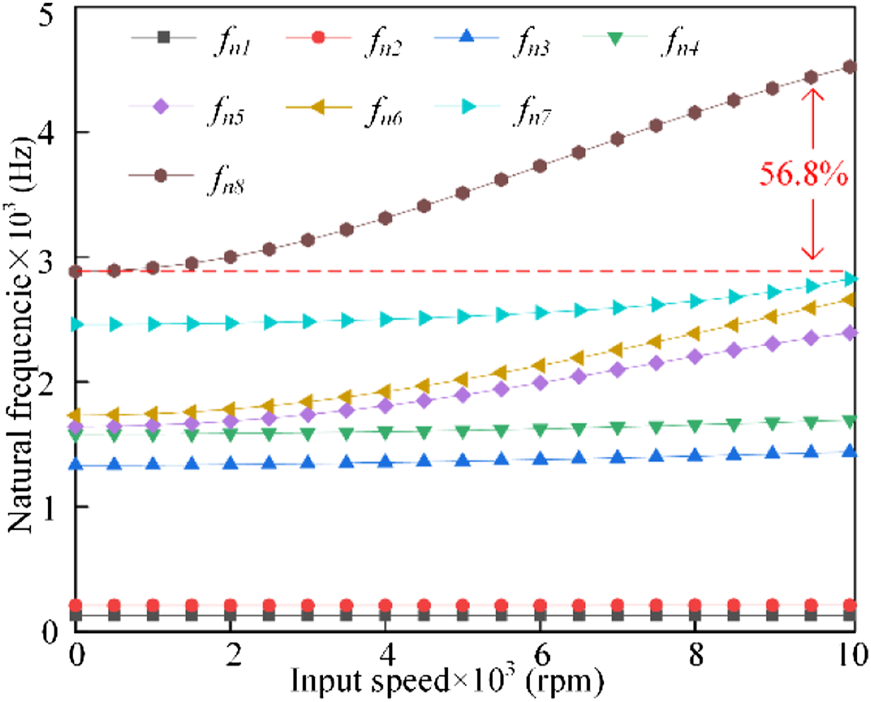
Figure 13 presents the typical mode shapes of the geared rotor system. Within the range from 0 r/min to 10,000 r/min, the fifth-order dominant mode shape changes from the torsional vibration of the first-stage pinion to the torsional vibration of the second-stage pinion at the speed of 10,000 r/min. The eighth-order dominant mode shape changes from the bending vibration of the shaft 1 to the torsional vibration of the first-stage pinion at the speed of 6000 r/min. The tenth-order dominant mode shape changes from the torsional vibration of the first-stage pinion to the bending vibration of the shaft 2 at the speed of 5000 r/min. It is evident that the dominant mode shapes of the geared rotor system changes obviously at high speed. The precession should be considered for obtaining accurate mode shapes at high-speed conditions. Model shapes of the geared rotor system (a) fifth mode (without precession) (b) fifth mode (10,000 r/min) (c) eighth mode (without precession) (d) eighth mode (6000 r/min) (e) tenth mode (without precession) (f) tenth mode (5000 r/min).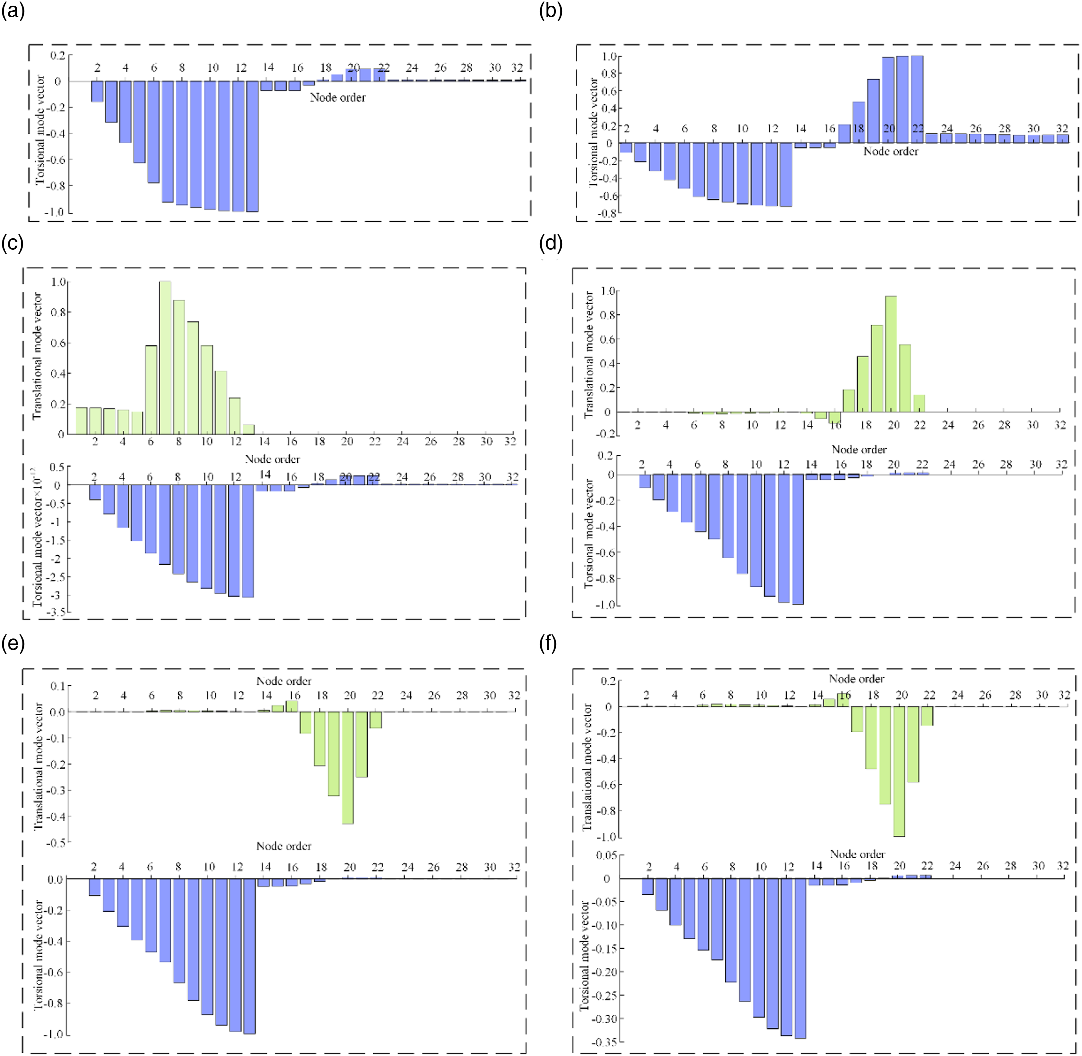
Natural characteristics of the housing
The finite element model of the gearbox housing is shown in Figure 14(a). Since the dynamic excitation of the gear transmission system is transmitted to the housing through the bearings, the dynamic response can be calculated by applying concentrated loads to the housing. In order to apply the bearing loads, the centralized mass nodes are established in the center of the bearing holes, and the coupling relationship of each degree of freedom between the inner surface nodes of the bearing holes and the mass nodes are defined. Then, the bottom of the gearbox housing is fully restrained. Finally, the modal analysis of the gearbox housing is carried out using the Lanczos method. Figure 12(b)–(f) show the first five order mode shapes and natural frequencies of the gearbox housing. (a) Finite element model (b) first mode (c) second mode (d) third mode (e) fourth mode (f) fifth mode.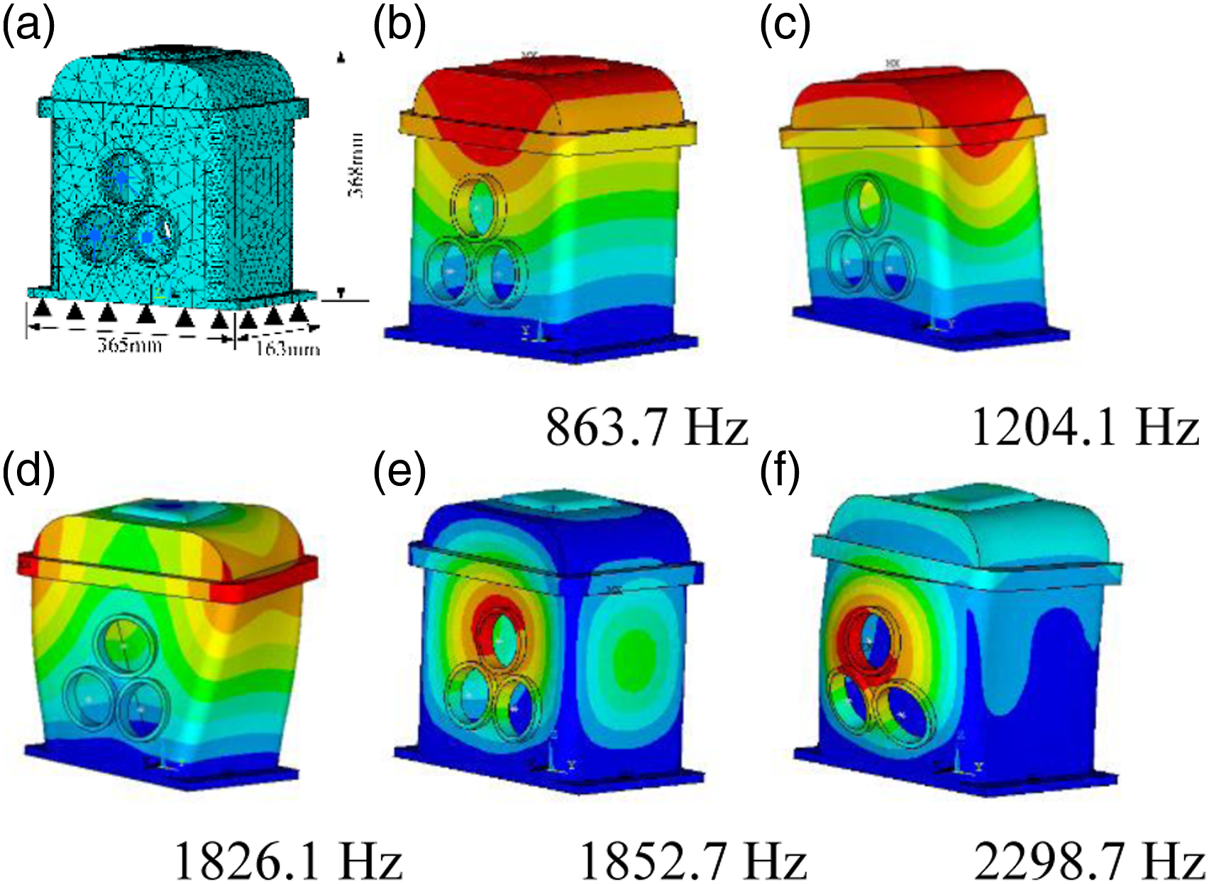
Gear dynamic load
The precession not only affects the natural characteristics of the geared rotor system, but also further affects the vibration and radiation noise of the gearbox. To illustrate the effect of the precession on the dynamic characteristics of the gearbox, the system dynamic loads with and without the precession are calculated.
The gear dynamic loads at different input speeds are calculated under the torque of 100 N·m. The eccentricities of the four gears are same (ep1 = eg1 = ep2 = eg2 = 0 μm). The comparison of gear load fluctuation amplitude (GLFA) at different input speeds is presented in Figure 15(a) and (b). It can be determined that before and after considering the precession, the GLFA and peak values of the first and second-stage gear transmission change little, and the curve is basically the same under low-speed condition. With the increases of input speed, the peak speeds of the gear dynamic load increase and the resonance region shifts. This is because the precession causes the natural frequencies of the geared rotor system to increase with the increases of input speed. Since the first-stage gear pair is high-speed gear transmission and the second-stage gear pair is low-speed gear transmission, it can be seen clearly that the precession has a greater impact on the dynamic load of the first-stage gear than that of the second-stage gear. When the input speed is 3100 r/min, considering the precession effect, the main excitation frequency components (5fm2) are close to the eighth-order natural frequency of the gear system, and the system has greater vibration energy. The peak speeds of the first-stage gear transmission increase from 4150 r/min to 4200 r/min, 5400 r/min to 5450 r/min, and the vibration of the system increases. The resonance region of gear dynamic load is obviously shifted, and the main resonance speed increases from 6500 r/min to 6550 r/min. The results demonstrate that the precession has great influence on the vibration of the geared rotor system at high speed. The high-speed gear transmission is more sensitive to the precession effect than the low-speed gear transmission. Gear dynamic load (a) GLFA of the first-stage gear transmission at different speeds (b) GLFA of the second-stage gear transmission at different speeds (c) Waterfall of the first-stage gear load (without the precession) (d) Waterfall of the first-stage gear load (with the precession).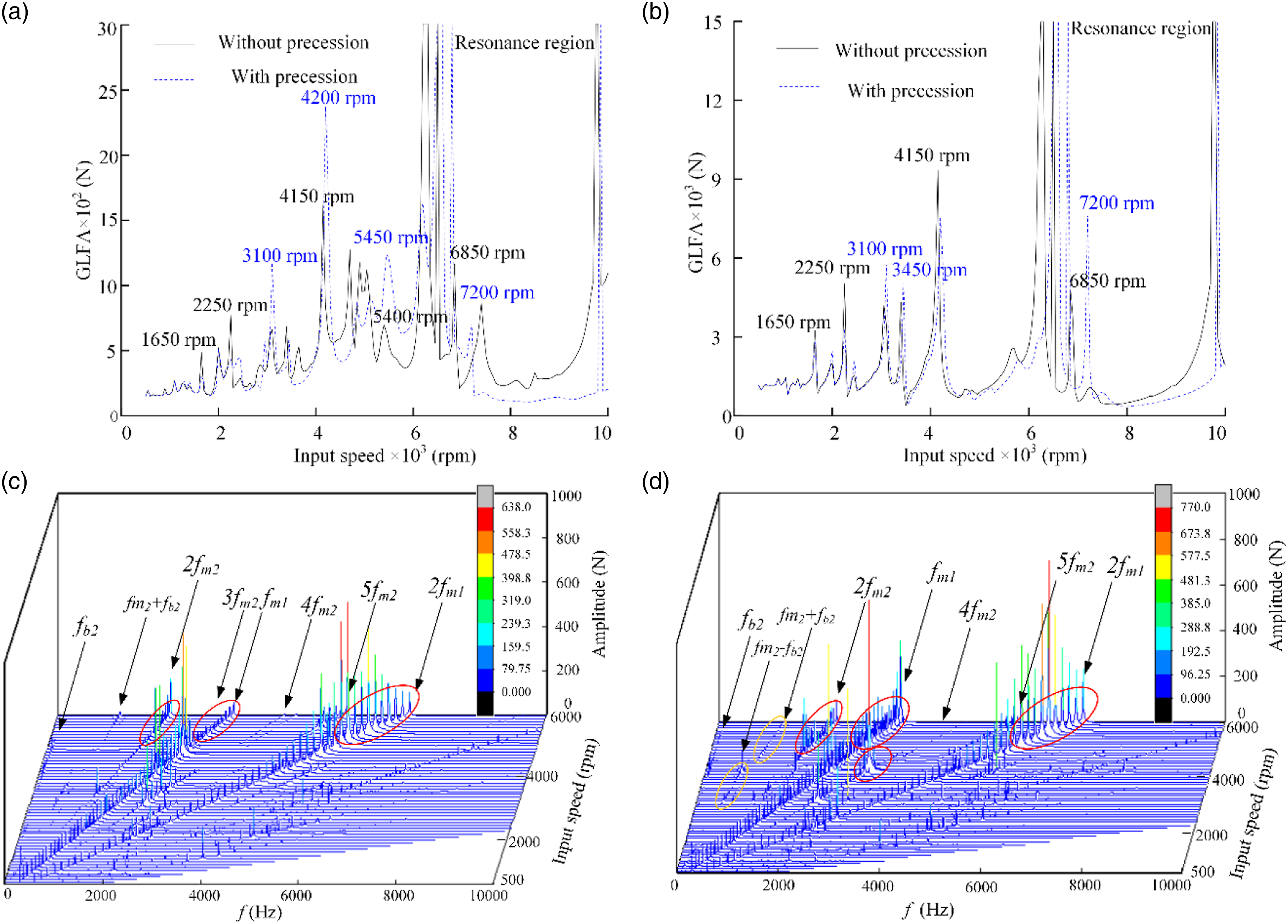
In order to further analyze the reasons for the change of the gear dynamic load, the waterfall of the first-stage gear load with and without the precession is obtained, as shown in Figure 15(c) and (d). It can be determined that with the increases of input speed, the frequency components are complex, the vibration energy in multiple regions increases, and new resonance peaks appear. At the low-frequency position, the modulation of the bearing passing frequency on the second-stage meshing frequency is obvious, and there are some obvious modulation frequencies (fm2 - fb2, fm2 + fb2). The first-stage gear transmission is affected by the precession effect, and the amplitudes of the first-stage meshing frequency and the second harmonic frequency region increase significantly under high speed condition.
Bearing dynamic load
Figure 16(a) and (b) present the curves of the bearing load fluctuation amplitude (BLFA) of the shaft 1 end (high-speed shaft) and the shaft 3 end (low-speed shaft) at different input speeds. It can be determined that the BLFA of the high-speed shaft changes greatly and the BLFA of the low-speed shaft changes less due to the precession effect. The change of the BLFA under low-speed condition is small, and the change of BLFA under high-speed condition is large. With the increases of speed, the influence of precession on bearing dynamic load becomes more and more obvious. Due to the influence of precession, the peak speeds of the bearing dynamic load increase and the resonance region shifts, which is basically consistent with the law of gear dynamic load. After the precession is included in the geared rotor system, the natural characteristics of the system change with the increases of speed. Because the natural frequencies of the system are far away from the excitation frequency components, there are no obvious peaks at 2250 r/min, 4700 r/min, 4900 r/min, and 7400 r/min. Therefore, for the geared rotor system at high speed, the influence of precession on the dynamic response of the system should be fully considered in the design stage. Bearing dynamic load (a) BLFA at different speeds (high-speed shaft end) (b) BLFA at different speeds (low-speed shaft end) (c) Waterfall of bearing load (without the precession) (d) Waterfall of bearing load (with the precession).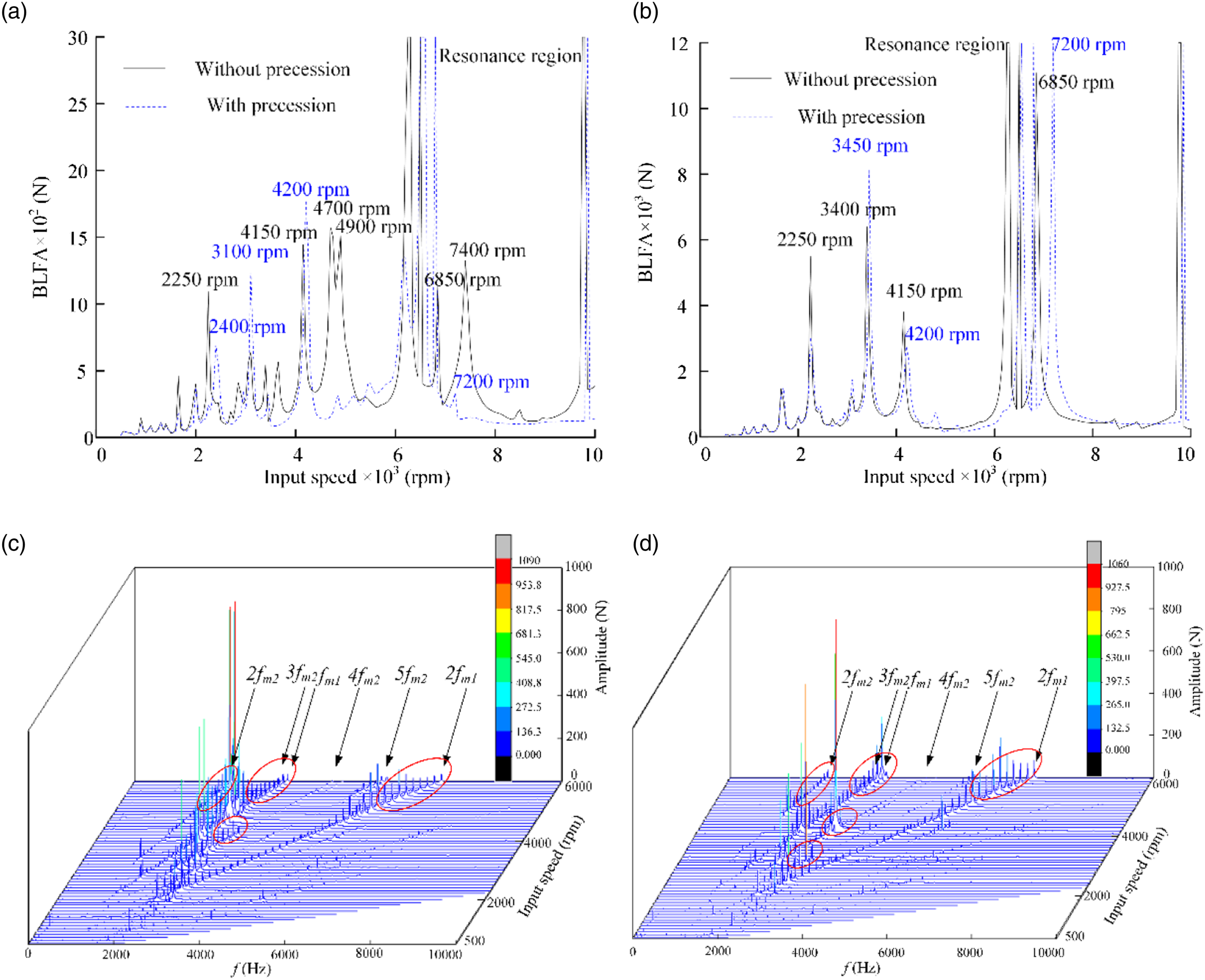
In order to further analyze the reasons for the change of the bearing dynamic load, the waterfall diagram of bearing dynamic load of the high-speed shaft with and without the precession is obtained, as shown in Figure 16(c) and (d). It can be determined that the frequency components of the bearing dynamic load changes under high-speed condition. Because the first-stage gear transmission is high-speed gear transmission, the precession effect has a great impact on the first-stage meshing frequency and its double frequency. There are obvious peak speeds deviation under high-speed condition. Compared with gear dynamic load, bearing dynamic load is less affected by precession effect. When the input speed is 4200 r/min, the main frequency components of the bearing dynamic load are 2fm2, 3fm2, and 4fm2, of which the energy of 3fm2 is the highest. Due to the influence of precession, the main frequency components become 3fm2 and 4fm2, of which the energy of 4fm2 is the highest.
Radiation noise
To quantify the effect of the input speed on the radiation noise of the gearbox, the effective sound pressure level (ESPL) is calculated to show the noise levels at different input speeds, as shown in equation (22)
The ESPL of the field points on the top and both sides of the gearbox is calculated at different input speeds, as presented in Figure 17. It can be determined that the ESPL has an increasing trend with the increases of input speed, and many peaks are clearly visible. However, considering the precession effect, the ESPL is affected by precession, and the peak position also shifts. Under the high-speed condition, the radiated noise of each field point of the gearbox increases obviously. This is because the peak speeds of the gear and bearing dynamic load increase and the resonance region shifts with the increases of input speed. When the precession effect is not considered in the gear system, the noise at the field points on both sides peak at the speeds of 3100 r/min, 3400 r/min, 4100 r/min, 4700 r/min, and 4900 r/min. This is because the dynamic load of the bearing vibrates violently at the same speeds. When the precession effect is considered in the gear system, due to the change of bearing dynamic load, the noise only has obvious peaks at 3100 r/min, 4200 r/min, and 4800 r/min. ESPL of field points on the top and both sides.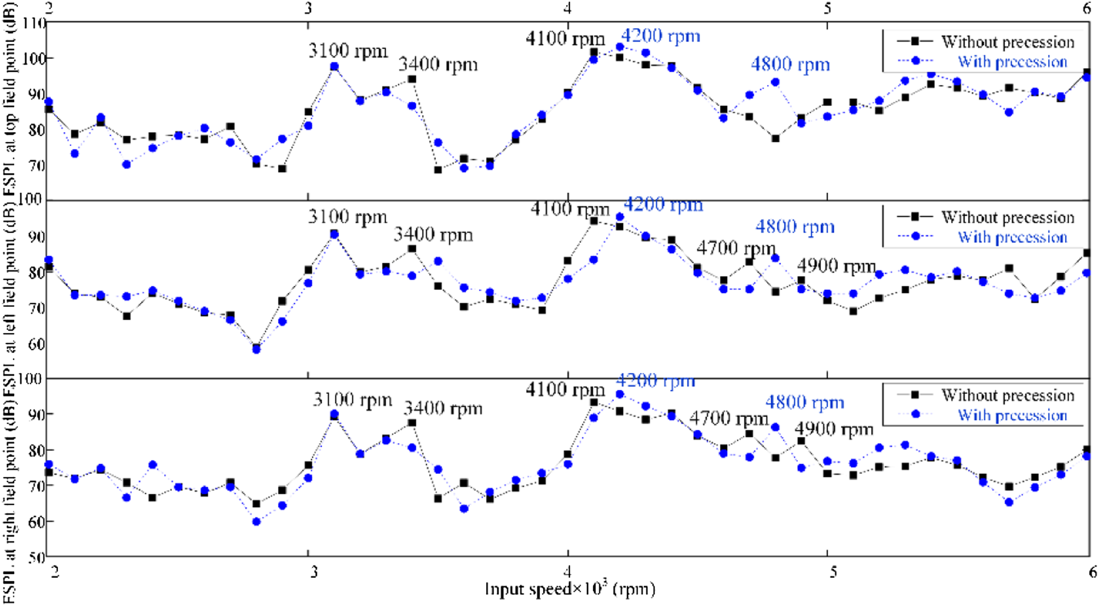
The waterfall of each field point of the gearbox with and without precession effect is shown in Figure 18. The radiated noise level is represented by the depth of color. It can be seen that the radial dark areas occur at the meshing frequency and its multiples, and resonance regions are generated near the third-order and fourth-order natural frequencies (1800 Hz–1900 Hz), the fifth-order, sixth-order, and seventh-order natural frequencies (2200 Hz–2600 Hz) and the eighth-order and ninth-order natural frequencies (3100 Hz–3200 Hz) of the housing. When considering the effect of precession, the waterfall changes obviously. With the increases of input speed, the resonance regions of each field point of the gearbox are enlarged and the color is deepened, and the noise is obviously enhanced. Compared with the noise on both sides of the gearbox, the noise on the top of the gearbox is greatly affected by the precession effect. Waterfall of gearbox at different field points (a) Right field point (without precession) (b) Right field point (with precession) (c) Left field point (without precession) (d) Left field point (with precession) (e) Top field point (without precession) (f) Top field point (with precession).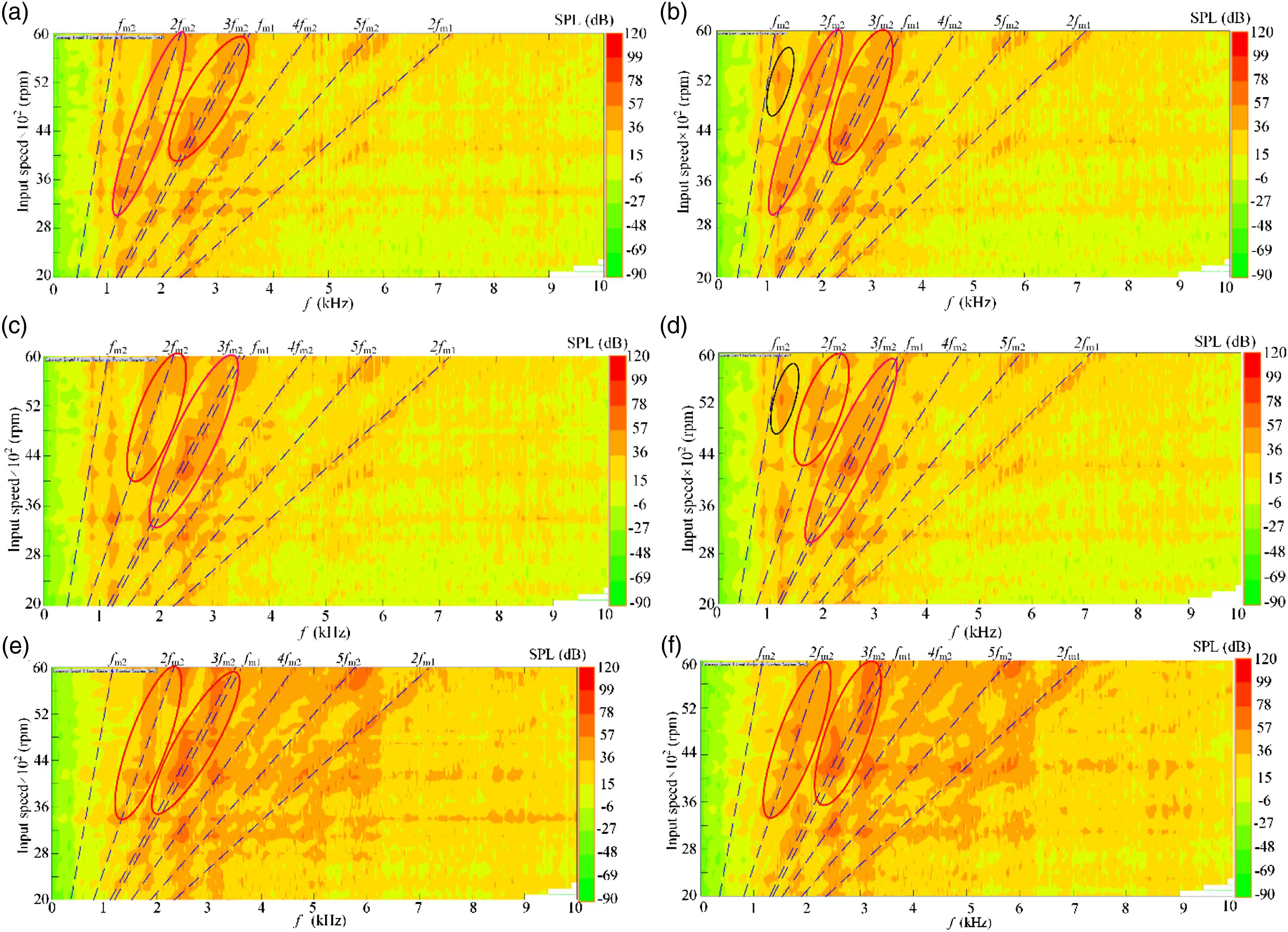
Conclusions
In this paper, an improved dynamic model of a gear-rotor-bearing system that considers the transmission error, initial bending, geometric eccentricity, and precession effect is developed. An extended computational method for a two-stage gearbox is proposed to address the vibro-acoustic propagation of the gearbox. The numerical predictions show good agreement with the experimental measurements. The influences of the precession on the vibration response and radiation noise of a two-stage gearbox are investigated. The main conclusions of this research can be summarized as follows. 1. With the increases of the input speed, the natural frequencies of the geared rotor system increase. When the input speed is 10,000 r/min, the eighth-order natural frequency of the system increases from 2883 Hz to 4522 Hz, with an increase of 56.8%. The dominant mode shapes of the geared rotor system changes obviously at high speed. The precession has a great influence on the high-order natural characteristics of the geared rotor system under high-speed condition. The precession should be considered for obtaining accurate mode shapes at high-speed conditions. 2. The influence of precession on the vibration and noise of the gearbox can be ignored at low speed. With the increases of input speed, the peak speeds of the first-stage gear transmission increase from 4150 r/min to 4200 r/min, 5400 r/min to 5450 r/min, and the vibration of the system increases. The main resonance speed increases from 6500 r/min to 6550 r/min. The peak speeds of the gear and bearing dynamic load increase and the resonance region shifts. The effect of precession on the dynamic load of the high-speed gear transmission is greater than that of the low-speed gear transmission. 3. Under the high-speed condition, the resonance regions of each field point of the gearbox are enlarged, and the noise is enhanced obviously. The noise on the top of the gearbox is greatly affected by the precession effect.
In summary, precession effect, which cannot be neglected, greatly affects the vibration and noise of the gearbox under high-speed condition. The initial bending of the shafts and the geometric eccentricity of the gears should be reduced. The precession effect should be attenuated or avoided in the gearbox design stage. The dynamic balance accuracy of the rotor system is improved to improve the stability of the system.
Future work will investigate the low-noise optimization of gearbox based on the proposed parametric model and numerical calculation method.
Footnotes
Declaration of conflicting interests
The author(s) declared no potential conflicts of interest with respect to the research, authorship, and/or publication of this article.
Funding
The author(s) disclosed receipt of the following financial support for the research, authorship, and/or publication of this article: This work supported by Research and Development Foundation of Xinjiang Province (grant numbers 2021B01003-1), Natural Science Foundation of Xinjiang Province (grant numbers 2021D01C050), National Natural Science Foundation of China (grant numbers 51665054).