
Abstract
The impulsive vibration induced by human running and jumping, object falling, striking during decoration, etc., significantly disturbs the learning, work, and life of people through building structure transmission. To study the influence of impulsive vibration in buildings, a vacant frame building was selected as a tested building. The vibration at each floor besides hitting spot would be measured when a solid metal ball falling freely hit the first floor of this building. The vibration response at each floor caused by the excitation above was simulated through a finite element method. The parameters of the simulation model were optimized according to measured results. Furthermore, the influence of building structure, the total amount of stories, and slab dimension on the transmission of vibration from 1 Hz to 80 Hz which can be perceived by human bodies was quantitatively studied. Results showed that the vertical weighted vibration acceleration level at each floor linearly decreased with the increase of the logarithm of the distance between each floor and the hitting spot. A prediction model of vertical weighted vibration acceleration level from 1 Hz to 80 Hz induced by the impulsive vibration in buildings was developed according to simulation results. The corrections relating to the number of story, building structure, slab span, slab length-to-width ratio, and slab thickness were respectively introduced in the model which can predict the vertical weighted vibration acceleration level at each floor above the hitting spot. The results of this study can provide a basis for the prediction and control of impulsive vibration caused by an impact source with great stiffness in buildings.
Keywords
Introduction
Vibration is an important factor affecting indoor environment. Only the vibration from 1 Hz to 80 Hz can be perceived by human bodies. 1 The impulsive vibration induced by human running and jumping, object falling, striking during decoration, and so on, is common in buildings. It significantly disturbs the learning, work, and life of people through building structure transmission. Disclosing transmission characteristics of impulsive vibration in buildings can provide a basis for the prediction and control of impulsive vibration.
Structural vibration responses are closely related to the frequency characteristics of excitation forces. 2 The impact forces from human walking, running, and jumping involve strong components of low frequency. The energy of floor vibration caused by these impact forces mainly distributes below 15 Hz.3,4 In the measurement of vibration and structure-borne sound transmission, a standard tapping machine is used to simulate light-weight impact sources such as footsteps with shoes. 5 The tapping machine drops five equally spaced force hammers of 0.5 kg from a height of 40 mm. The bang machine which can drop a 7.3 kg tire from a height of 85 cm or a 2.5 kg rubber ball which falls freely from a height of 100 cm is used to simulate heavy-weight impact sources such as human running and jumping.6,7 Impact sources such as fallen rigid objects and hammers used in building decoration have great stiffness and the duration of these impacts on structures is shorter. Compared with that induced by human walking, running, and jumping, the energy of structural vibration caused by these impact sources mainly distributes in a higher frequency range. 8 The vibration from a bang machine or rubber ball cannot simulate the vibration effects caused by stiffer impact sources. Auersch and Said 9 measured the floor vibration excited by a force hammer with a rigid tip and found that the vibration energy mostly distributed above 10 Hz and contained strong components of medium and high frequency.
The vibration responses of building structures are related to building configurations. Accurate vibration responses can be obtained through field tests and test results are only applicable for tested buildings. Thus, the influences of building structural parameters on vibration transmission cannot be studied quantitatively through tests. Numerical calculation methods, such as the finite element method, boundary element method, and finite difference method,10–12 can more accurately simulate the vibration responses of structures in buildings. Under an exciting force, such as human walking and running, long span or slender floors would be more susceptible to vibration. 13 Adding nonstructural elements such as partition walls could reduce floor vibration, but it would lead to a rise of vibration transmission between two adjacent stories. 14
Few studies have reported the transmission characteristics of vibration induced by indoor impact sources in high-rise buildings. When a receiver point is far from the vibration source, the vibration responses with a high signal-to-noise ratio will be not easy to obtain in high-rise buildings unless sufficient vibration energy from an excitation source is input into building structures. Asakura et al.
15
use a force hammer of 6.7 kg as the impact source to measure the vibration response at each floor in a frame building with five stories. Based on the field tests, Auersch and Said
9
proposed an empirical model on the attenuation of floor vibration caused by a hammer impact. The relation between the amplitude of vibration velocity A and the transmission distance r could be described by equation (1). On the basis of the impedance theory and the dynamic stiffness matrix method, several analytical models which could predict vibration responses in frequency domain were developed.16,17

For different frequencies of vibration, the sensitivity of human bodies is different. The frequency weighted acceleration from 1 Hz to 80 Hz is used in ISO 2631-1 18 for the evaluation of vibration influence on humans. Because the attenuation of horizontal vibration is faster than that of vertical vibration and human bodies are not sensitive to horizontal vibration, only vertical vibration is usually considered in the evaluation of environmental vibration influence. So far, few models specifically predict vertical vibration from 1 Hz to 80 Hz induced by an impact source in buildings.
In this study, the transmission characteristics of impulsive vibration caused by a solid metal ball impact in buildings were quantitatively studied through field tests and numerical simulations. A prediction model of vertical vibration induced by the solid metal ball impact was established.
Methods
Test methods
To study the transmission characteristics of impulsive vibration in buildings, a vacant frame building with 15 stories was selected as a tested object. The vibration at each floor besides hitting spot would be measured when a solid metal ball falling freely hit the first floor of this building.
The tested building is in the shape of a cuboid (32.8 m × 27.8 m × 57.2 m). The horizontal and vertical layouts of this building are presented in Figure 1. The cross-sectional dimensions of concrete frame columns on the 1st–2nd floors, 3rd–6th floors, 7th–9th floors, and 10th–15th floors are 0.75 × 0.75 m, 0.7 × 0.7 m, 0.65 × 0.65 m, and 0.6 × 0.6 m, respectively. The cross-sectional dimensions of the girders and beams are 0.35 × 0.7 m and 0.25 × 0.6 m, respectively. The slab thickness is 0.12 m. The layouts of tested building and sampling points: (a) horizontal layout and (b) vertical layout.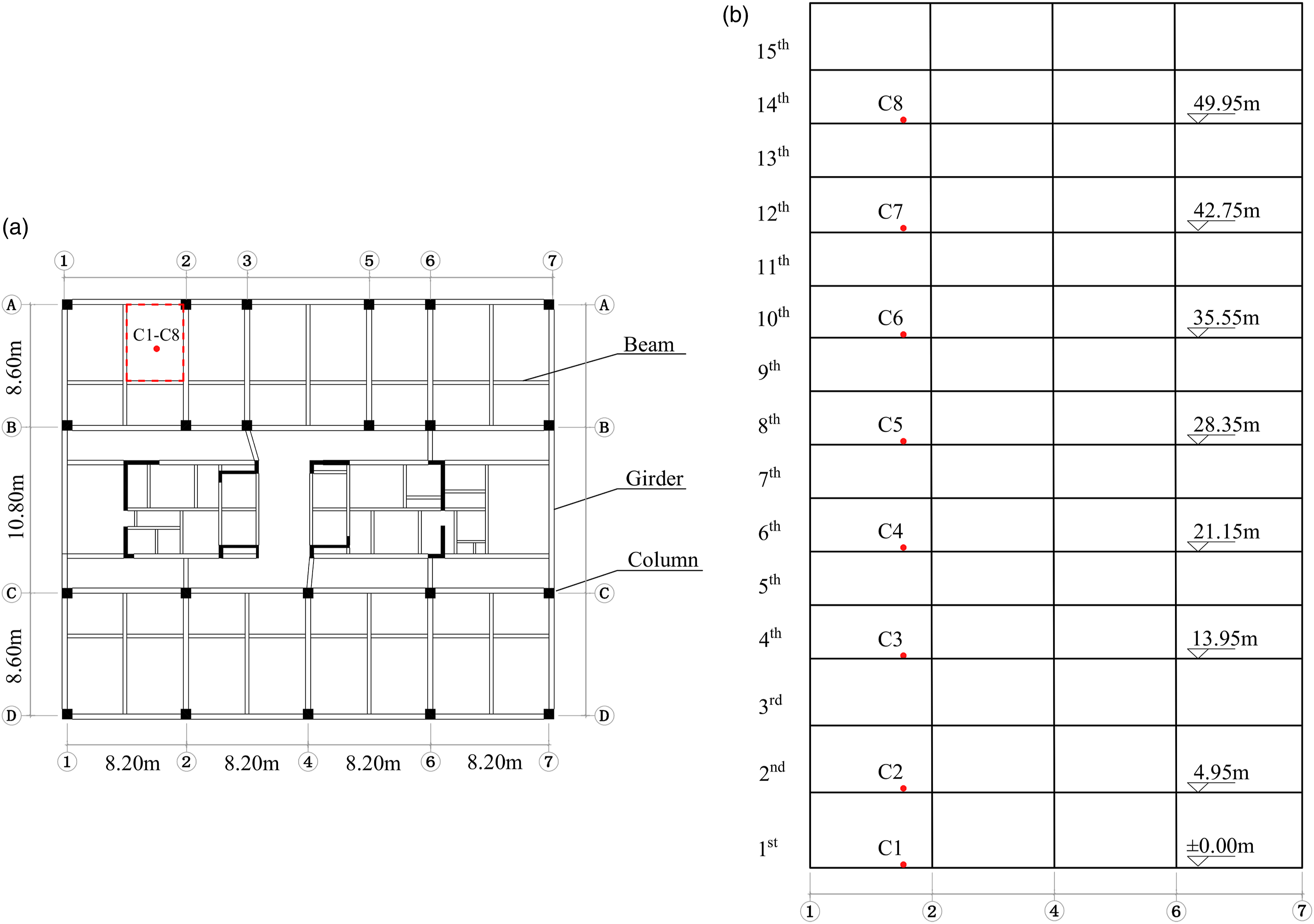
A solid metal ball with a great stiffness (0.15 m in diameter and 13.77 kg in weight) was used as the impact source. It fell freely from the height of 0.6 m above the first floor and hit the floor. The hitting spot (i.e., sampling point C1) was located at the central point of the area enclosed by a dashed line as shown in Figure 1(a). The sampling points C2–C8 were set at the 2nd, 4th, 6th, 8th, 10th, 12th, and 14th floor, respectively, in the vertical direction of the hitting spot. The vibration acceleration data at each sampling point was obtained and the model of the accelerometer used was PCB 356B07.
Based on vibration sampling data, the maximum of vertical weighted vibration acceleration level from 1 Hz to 80 Hz (VLZ) at each sampling point was calculated according to equations (2)–(3)
18


Simulation methods
A finite element model of tested building was established through the finite element analysis software ABAQUS (version 6.14). The vibration response at each floor would be simulated when the solid metal ball hit the first floor of the building. The parameters of the simulation model were optimized according to measured results. Furthermore, the finite element models of typical concrete buildings were set up. The vibration response at each floor caused by the impact of solid metal ball was simulated under different parameters of building structure.
The finite element model of tested building
The finite element model of tested building was established according to the actual structure and dimensions specified in 2.1. The beams and columns were modeled by a beam element. The slabs and infill walls were modeled by a shell element. All nodes at the bottom of building in the model were fixed. The elastic modulus, Poison’s ratio, and density of concrete materials in beams, columns, and slabs were 32.5 Gpa, 0.2, and 2500 kg/m3, respectively. The elastic modulus, Poison’s ratio, and density of materials in infill walls were 2 Gpa, 0.15, and 600 kg/m3, respectively. Energy dissipation was modeled by Rayleigh damping and the damping ratio was set as 0.02. 19 The grid size in the model was 0.5 m which was less than 1/12 of the minimum wavelength in the frequency range of interest (1 Hz–80 Hz). 20 The time step was set as 0.00625 s in simulation. An impulsive vibration whose vertical vibration acceleration values were from the sampled data at C1 under the impact of metal ball was loaded at C1 of simulation model.
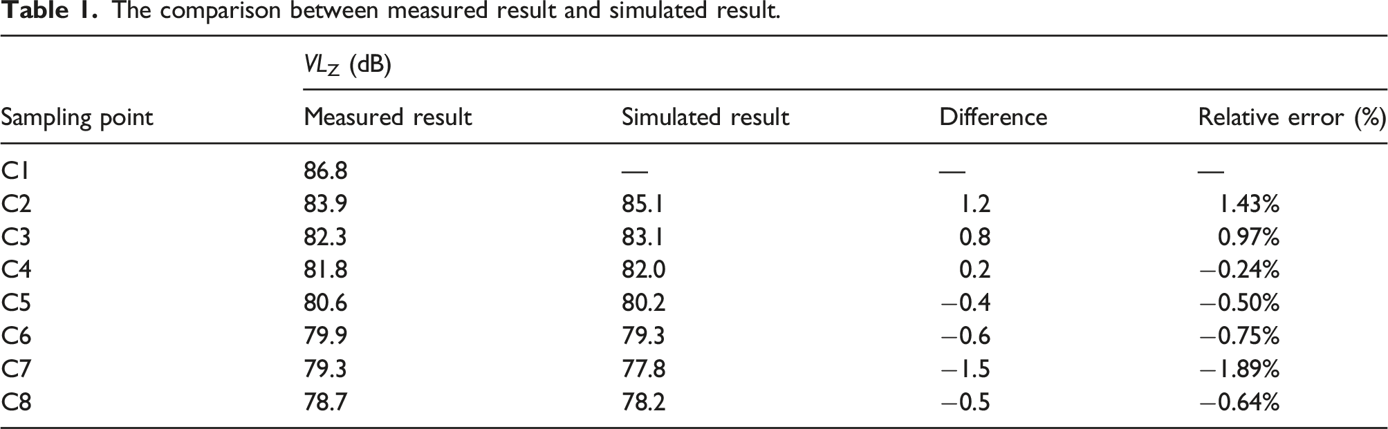
The comparison between measured result and simulated result.
The model of typical buildings
Frame structure and shear wall structure are typical two types of structures in concrete buildings. The typical structural parameters of these two types of buildings were selected according to the Code for Design of Concrete Structures (GB 50010-2010, China)
21
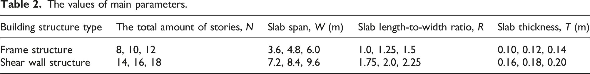
and the finite element models of these buildings were established. The horizontal layout of buildings is presented in Figure 2. The height of each story was 3.0 m in building. The parameters of building structure type, the total amount of stories (N), and the slab dimensions including span (W), length-to-width ratio (R), and thickness (T) were chosen as shown in Table 2. The span of slab was represented as a, the slab width in Figure 2. In the building with a frame structure, the cross-sectional dimensions for columns and beams were 0.5 × 0.5 m and 0.3 × 0.6 m, respectively. In the building with a shear wall structure, the thickness of load-bearing wall was 0.2 m. The damping ratio in building models took 0.02. The results from modal analysis indicated that the fundamental natural periods of frame buildings and shear wall buildings were 0.37–1.17 s and 0.30–0.98 s, respectively. Marked by a cross in Figure 2, the hitting spot of metal ball lied on the first floor of building. An impulsive vibration whose vertical vibration acceleration values were from the sampled data at C1 under the impact of metal ball was loaded at the hitting spot of simulation model. The vibration response at each floor in the vertical direction of the hitting spot was calculated. The horizontal layout in (a) frame buildings and (b) shear wall buildings. The values of main parameters.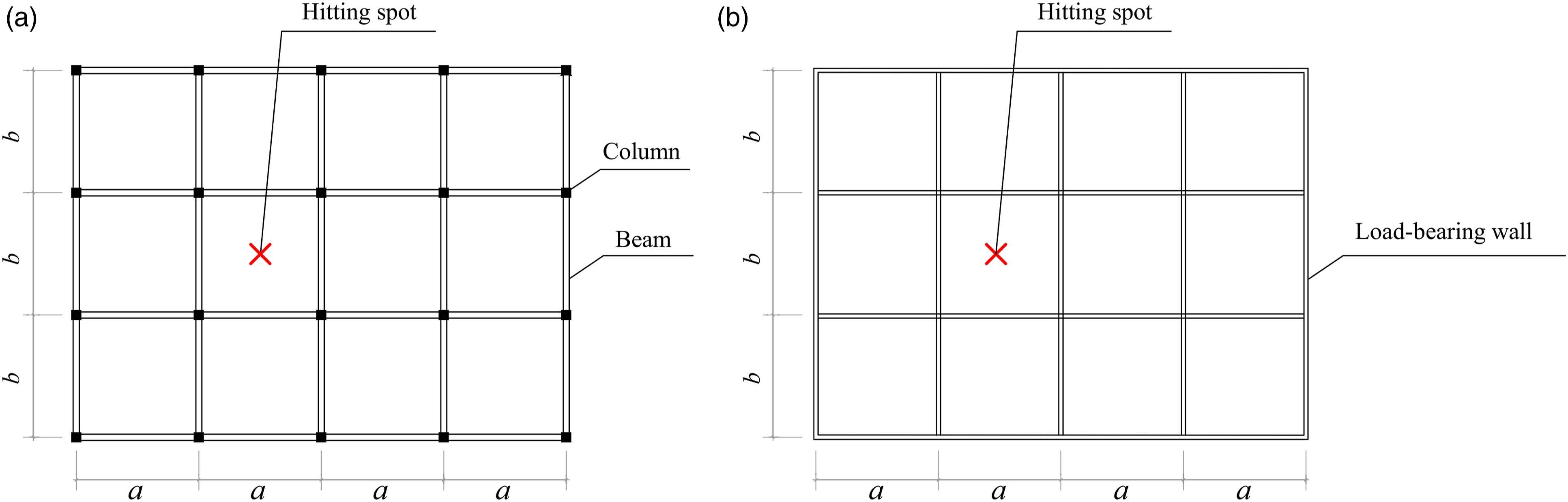
Statistical analysis
The attenuation of vertical weighted vibration acceleration level (ΔVLZ) at each floor was calculated by equation (4). A previous study showed that the vibration attenuation per story decreased with the rise of story.
9
In this study, the ΔVLZ at each floor and the logarithm of the distance between each floor and the hitting spot, log10(d), were fitted by equation (5)

Results and discussion
Test results and analysis
The vibration response at the hitting spot C1 under the impact of metal ball is shown in Figure 3. Since the metal ball bounced several times on the floor, several peaks of vibration acceleration occurred in Figure 3. The VLZ at each floor is shown in Table 1. ISO 2631
18
noted that the median perception threshold of a vertical frequency weighted vibration for a fit person is approximately 0.015 m/s2 (83.5 dB) and the minimum perception level can be down to around 0.010 m/s2 (80 dB). Occupants in residential buildings will be uncomfortable when the vibration magnitudes are only slightly in excess of the perception level mentioned above.
1
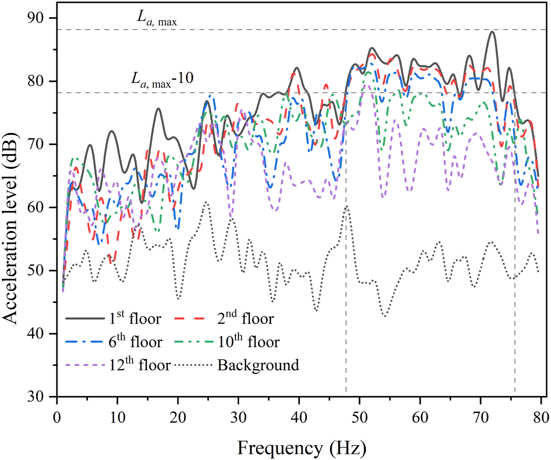
The spectra of vibration acceleration level at different floors are presented in Figure 4 where La, max is the maximum vibration acceleration levels from 1 Hz to 80 Hz in tested building. As shown in Figure 4, the dominant frequency components of impulsive vibration ranged from 48 Hz to 76 Hz. The measured vibration acceleration at hitting spot C1. The measured spectra of vibration acceleration levels at different floors.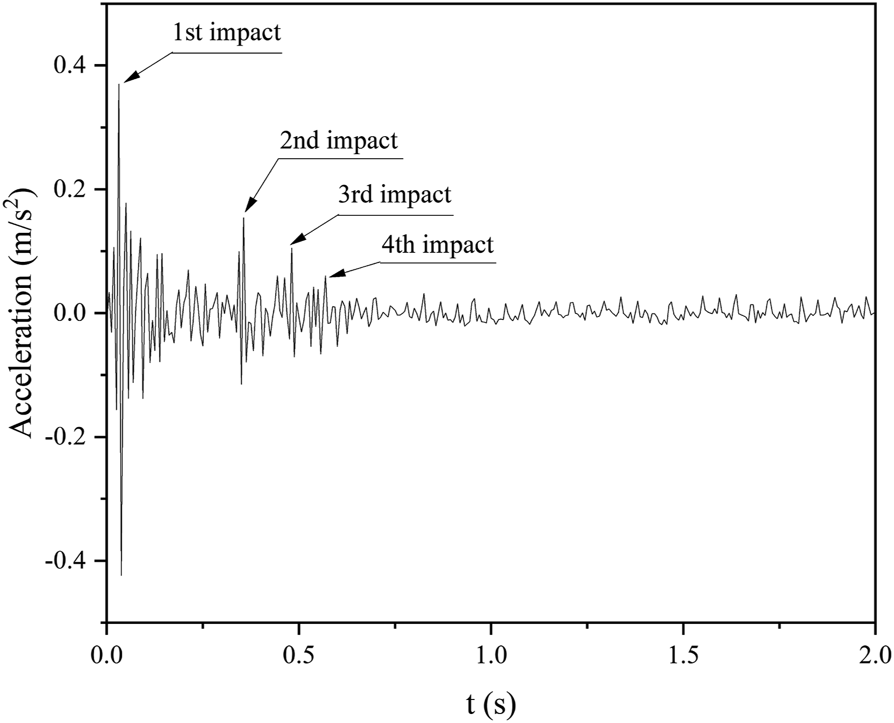
The fitting result of the ΔVLZ at each floor and the logarithm of the distance between each floor and the hitting spot, log10(d), is presented in Figure 5. As shown in Figure 5, the ΔVLZ at each floor increased with the increase of the number of story. ΔVLZ was linearly correlative with log10(d) and the coefficient of determination (R2) was 0.945. The measured ΔVLZ at each floor.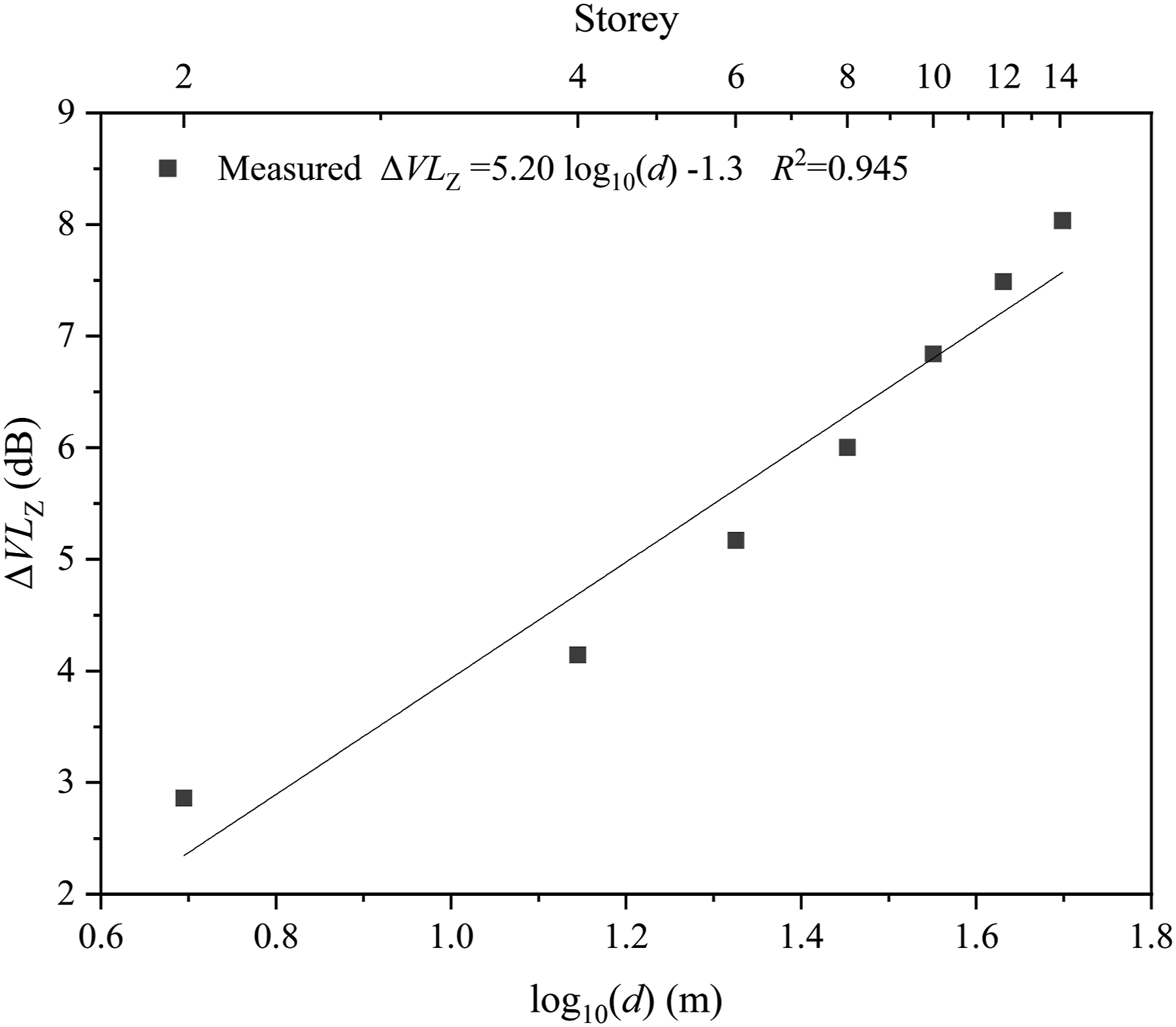
Simulation results and analysis
The influence of building structure and the total amount of stories on vibration transmission
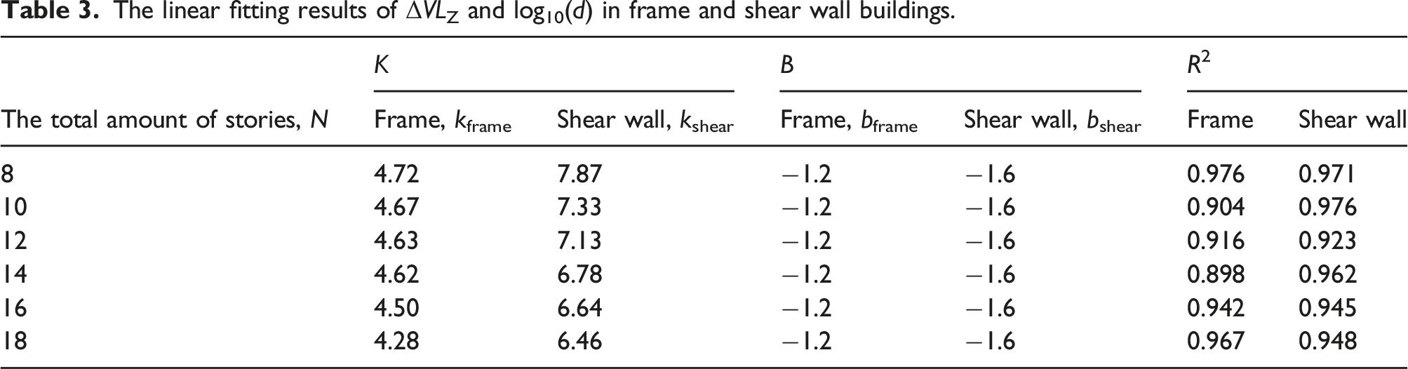
The linear fitting results of ΔVLZ and log10(d) in frame and shear wall buildings.
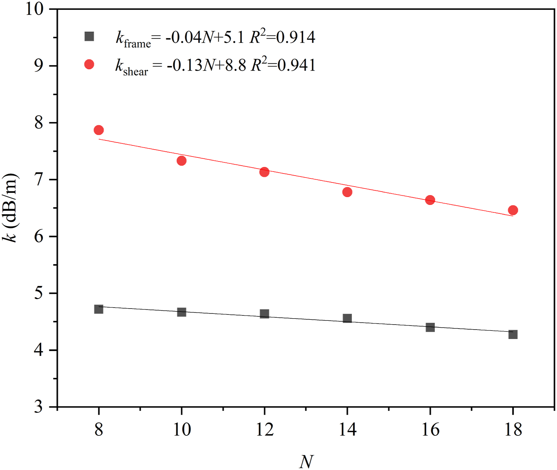
The vibration attenuation rate, k, in frame buildings and shear wall buildings of 8–18 stories.
The vibration attenuation rate, k, in shear wall building was greater than that in frame buildings. It was related to the fact that vertical vibration transmits mainly through load-bearing walls in shear wall buildings or through load-bearing columns in frame buildings. The impedance of load-bearing walls is greater than that of load-bearing columns. 22 The vibration attenuation rate, k, would decrease when the total amount of stories increased, which was similar with the result from Kwak et al. 23 When the total amount of stories increases, the vertical load from building itself will increase. Thus, the vertical vibration amplitude of each mass point in building will decrease when the exciting force is identical. Correspondingly, the dissipation of vibration energy induced by the friction in the process of relative motion of mass points decreases, which will lead to a decrease of k.
The influence of slab dimension on vibration transmission
The influence of slab dimension on the vibration transmission in frame buildings and shear wall buildings are presented in Figures 7 and 8, respectively. As shown in Figures 7 and 8, when the slab span increased from 3.6 m to 9.6 m, the vibration attenuation rate, k, would increase from 4.24 dB/m to 6.94 dB/m in frame buildings and from 6.46 dB/m to 12.03 dB/m in shear wall buildings. When the slab length-to-width ratio increased from 1.0 to 2.25, the vibration attenuation rate, k, would increase from 4.24 dB/m to 8.17 dB/m in frame buildings and from 6.46 dB/m to 13.72 dB/m in shear wall buildings. It indicated that the vibration attenuation rate, k, in frame buildings and shear wall buildings increased with the increase of slab span or length-to-width ratio. This result can be elucidated by the fact that when the slab span or length-to-width ratio increases, the vertical stiffness of slab will decrease and the vertical vibration amplitude of each mass point in slab will increase when the exciting force is identical. Correspondingly, the dissipation of vibration energy induced by the friction in the process of relative motion of mass points increases. The influence of slab dimensions on the vibration transmission in frame buildings: (a) W = 3.6–9.6 m, R = 1.0, T = 0.10 m; (b) W = 3.6 m, R = 1.0–2.25, T = 0.10 m; and (c) W = 3.6 m, R = 1.0, T = 0.10–0.20 m. The influence of slab dimensions on vibration transmission in shear wall buildings: (a) W = 3.6–9.6 m, R = 1.0, T = 0.10 m; (b) W = 3.6 m, R = 1.0–2.25, T = 0.10 m; and (c) W = 3.6 m, R = 1.0, T = 0.10–0.20 m.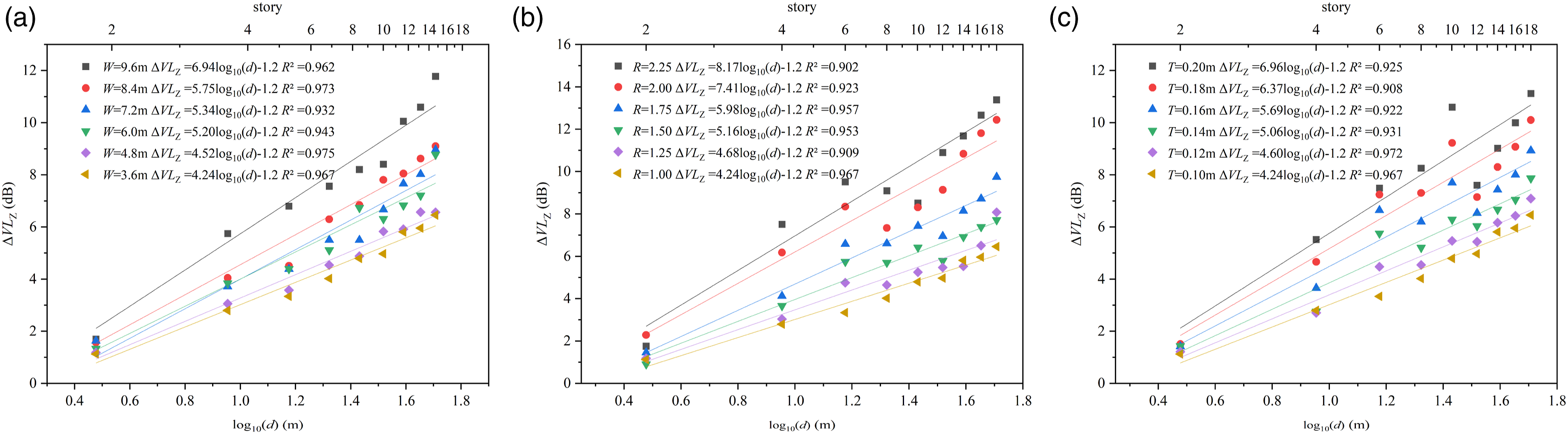
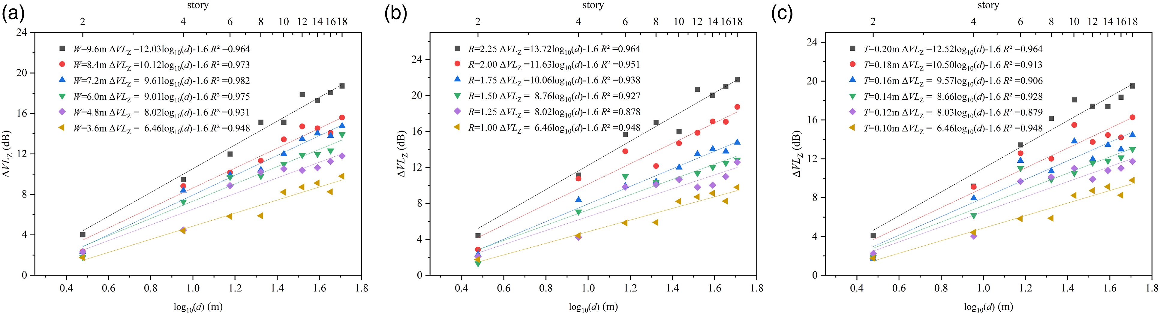
It could also be seen from Figures 7 and 8 that when the slab thickness increased from 0.10 m to 0.20 m, the vibration attenuation rate, k, would increase from 4.24 dB/m to 6.96 dB/m in frame buildings and from 6.46 dB/m to 12.52 dB/m in shear wall buildings. It indicated that the vibration attenuation rate, k, would increase in two types of buildings when the slab thickness increased, which was similar with the result from Sanayei et al. 24 The slab impedance would increase when the slab became thicker, which resulted in faster attenuation of vertical vibration in building.
The relationships between the vibration attenuation rate (k) and the slab dimensions including slab span, slab length-to-width, and slab thickness are presented in Figure 9. As shown in Figure 9, k was linearly correlative with slab span, slab length-to-width, and slab thickness in two types of buildings and the coefficients of determination (R2) were all greater than 0.9. The vibration attenuation rate, k, in frame and shear wall buildings with different slab dimensions: (a) with a different slab span, W; (b) with a different slab length-to-width ratio, R; and (c) with a different slab thickness, T.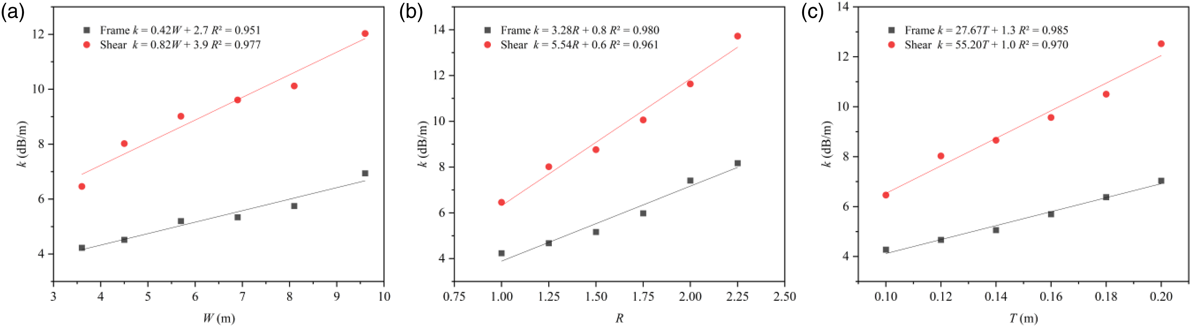
According to simulation results, increasing the slab span, slab length-to-width ratio, and slab thickness is conductive to reducing the transmission of impulsive vibration in buildings. Furthermore, an alternative to mitigate the impulsive vibration in buildings is to install damping devices within the buildings or connect them to the adjacent buildings through dampers.25,26
A prediction model of VLZ induced by the impulsive vibration in building and its verification
A prediction model of VLZ
Based on simulation results, a prediction model of VLZ induced by the impulsive vibration from a solid metal ball impact in building was developed (see equation (6)). The model can predict the VLZ at each floor above the hitting spot on the basis of the vibration at a hitting spot. This model is only applicable for frame buildings and shear wall buildings. (1) The correction term of the number of story, C
F

To predict the vibration influence at each floor caused by the impulsive vibration in building, a correction term, C
F
, relating to the number of a story was introduced. C
F
is the ΔVLZ at the nth floor in a frame building where the slab span, length-to-width ratio, and thickness were 3.6 m, 1.0, and 0.10 m, respectively. According to the linear fitting results in Table 3 and Figure 6, C
F
can be determined by equations (7)–(8) (2) The correction term of building structure, C
S


To predict the vibration influence at each floor in shear wall buildings, a correction term, (3) The correction term of slab span, C
W


A correction term, C
W
, relating to the slab span was introduced to consider the influence of slab span on vibration transmission. C
W
is the difference of ΔVLZs at the nth floor in frame buildings or shear wall buildings when the slab span is W and when the slab span is 3.6 m. According to the linear fitting results in Figures 7–9, ΔVLZ can be calculated by equations (11)–(13) (4) The correction term of slab length-to-width ratio, C
R


A correction term, C
R
, relating to the slab length-to-width ratio was introduced to consider the influence of slab length-to-width ratio on vibration transmission. C
R
is the difference of ΔVLZs at the nth floor in frame buildings or shear wall buildings when the slab length-to-width ratio is R and when the slab length-to-width ratio is 1.0. According to the linear fitting results in Figures 7–9, C
R
can be calculated by equations (14)–(16) (5) The correction term of slab thickness, C
T


A correction term, C
T
, relating to the slab thickness was introduced to consider the influence of slab thickness on vibration transmission. C
T
is the difference of ΔVLZs at the nth floor in frame buildings or shear wall buildings when the slab thickness is T and when the slab thickness is 0.10 m. According to the linear fitting results in Figures 7–9, C
T
can be calculated by equations (17)–(19)


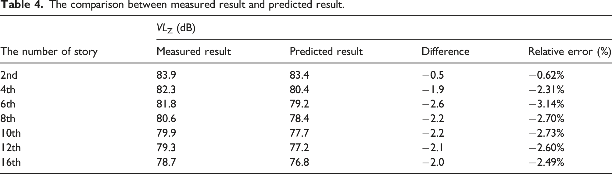
The verification of the prediction model of VLZ
The comparison between measured result and predicted result.
Conclusions
The transmission characteristics of vertical vibration caused by a solid metal ball impact in buildings were studied. The VLZ at each floor linearly decreased with the increase of the logarithm of the distance between each floor and a hitting spot (log10 d). The vibration attenuation rate (k), defined as the attenuation of VLZ per log10(d), was 2.18–3.15 dB/m greater in shear wall buildings than that in frame buildings. The k in frame buildings and shear wall buildings would decrease by 0.04 dB/m and 0.13 dB/m, respectively, when the total amount of stories increased by one story. When the slab span, slab length-to-width ratio, or slab thickness increased by one unit, k in frame building would increase by 0.42 dB/m, 3.28 dB/m, or 27.67 dB/m and k in shear wall building would increase by 0.82 dB/m, 5.54 dB/m, or 55.20 dB/m. Based on simulation results, a prediction model of VLZ induced by the impulsive vibration in buildings was developed. The corrections relating to the number of story, building structure, slab span, slab length-to-width ratio, and slab thickness were respectively introduced in the model to predict the VLZ at each floor above the hitting spot. The results of this study can provide a basis for the prediction and control of impulsive vibration from an impact source with great stiffness in buildings.
Footnotes
Declaration of conflicting interests
The author(s) declared no potential conflicts of interest with respect to the research, authorship, and/or publication of this article.
Funding
The author(s) received no financial support for the research, authorship, and/or publication of this article.