
Abstract
In this paper, the modulus prediction of NP-C/C is completed by establishing a multiscale finite element model, and the influence weight analysis of the modulus is carried out by using the analytical homogenization method. Firstly, three Micro-RVE, including unidirectional composites, short fiber reinforced composites and porous matrix, are established to characterize the layers of NP-C/C. Then, the finite element model is used for homogenization and passed upward into Meso-RVE, and the modulus prediction is completed. Finally, the analytical homogenization method is used combined with the MATLAB® script to analyze the influence weight of the modulus by adjusting the parameters. The results show that the average errors of stiffness coefficient prediction values obtained based on the analytical homogenization method are only 6.0% relative to the experimental values, which are lower than 25.3% of the finite element model. The modulus prediction method given in this study does not need to establish a micromechanical model with complex structure, and can be directly completed by computer script when the prediction accuracy is met, which is simple and feasible.
Keywords
Introduction
Carbon/Carbon (C/C) composite are considered to be one of the most promising high temperature materials 1 due to their high specific strength and specific modulus, excellent ablation resistance and thermal insulation properties. 2 Needle-punched carbon fiber preforms are made by laying short-chopped fiber felt between layers of unidirectional fiber bundles and then densely needling; 3 the purpose of the needle-punched is to hook the short fibers in the fiber felt into the thickness direction, 4 thereby increasing the strength of the preform thickness direction. Chemical Vapor Infiltration (CVI) is used for the densification of preforms, which refers to the placement of needle-punched carbon fiber preforms in hydrocarbon gases and vapor deposition until the inter-fiber pores are filled; 5 Liquid-phase impregnation refers to the preform impregnated in the resin and heated to generate a pyrolytic carbon matrix;6 The two processes are combined to form Needle-Punched Carbon/Carbon (NP-C/C) composite with some strength in the thickness direction. The needling process improves the interlaminar strength of 2D composites, and 2.5D NP-C/C is simpler to process, cheaper to produce, and easier to batch produce than 3D woven composites. 7
Needle-punched Carbon/Carbon composites require multiscale analysis because of their properties that combine fiber arrangement, needling process, matrix, interface and pore distribution. In terms of experimental observations: Roy et al. 8 observed the effects of needling density and needling depth on microscale fiber orientation, and analyzed the effect of needling process on tensile strength. Drach et al. 9 determined the shape distribution and porosity of pores in the pyrolysis carbon matrix according to the specimens made by CVI, and gave the influence of pores on elastic properties. Bradley et al. 10 provided shear failure experimental measurements in three ply forms, with shear failure stresses ranging from 30–45 MPa in-plane and 8–22 MPa out-of-plane, and shear modulus ranging from 6–16 GPa in-plane and 1–3 GPa out-of-plane. Based on the results of X-ray scan, Piat et al. 11 simplified the layered form and material properties, established a micromechanical model to describe the elastic behavior, and determined the elastic modulus of each layer and the stiffness coefficient ofNP-C/C. Cao et al. 12 studied the failure mode of the composite, and observed that the interface disbonding under shear load was one of the main failure modes. Microscopic toughening was also analyzed, 13 and after using carbon nanotubes to toughen the interface, the shear strength measured by nanoindentation characterization experiments increased by 80%; Macro-Sample have also been tested, 14 and the failure mode of sandwich composite blades depends on core stiffness and surface texture.
In terms of Finite Element (FE) model: Yu et al. 15 based on the discrete grayscale image of Micro-CT, established a three-dimensional model that can accurately reflect the needling effects and microstructure, which can better reveal the failure mechanism under tensile and compressive loads; however, shape reconstruction is only for specific specimens, and the generalizability of prediction method is poor. Xie et al. 16 and 17 selected and established four typical RVEs for predicting the effective performance of single needling regions and overlapping needling region by observing the microstructure of NP-C/C, taking into account local geometric features such as fiber fracture and deflection. Due to the increased complexity of the finite element model due to the high needling density and the presence of overlapping needled fibers, it is not possible to further analyze the influence of geometric parameters on macroscopic properties. Xu et al. 18 and Zhang et al. 19 used RVE to establish a micromechanical layered model to express the elastic properties of NP-C/C. In order to accurately calculate the material properties, the model needs to express the combined action results of fiber, matrix and porosity at the same time, but the calculation process is more complicated. Based on Micro-CT scan results, Meng et al. 20 established Meso-RVE and predicted the elastic modulus of NP-C/C by hierarchical modeling that took into account material changes caused by needle-punch, including fiber dislocation, fiber distribution, and matrix effects.
Through the above literature review, it is found that the modulus prediction of NP-C/C can be accurately completed by establishing multiscale models combined with finite element analysis. However, due to the complexity of the microstructure, it is necessary to repeatedly check the finite element model to improve the prediction accuracy. In addition, analytical homogenization methods 21 are used to predict modulus with the help of a series of numerical formula, including the Mori-Tanaka method, 22 the Halpin-Tsai formula, 23 the Chamis empirical formula, 24 and the classical laminate theory. 25 The analytical homogenization method used in this paper does not require complex meshing and impose the periodic boundary conditions, which can reduce the complexity of model construction, and can provides an effective method for predicting the modulus and improves the applicability of the method. At the same time, while using this method for predicting modulus, we further evaluate the influence of each parameter on the modulus in combination with the MATLAB® script, which can be further used for model structure optimization.
Model construction of needle-punched carbon/carbon composites
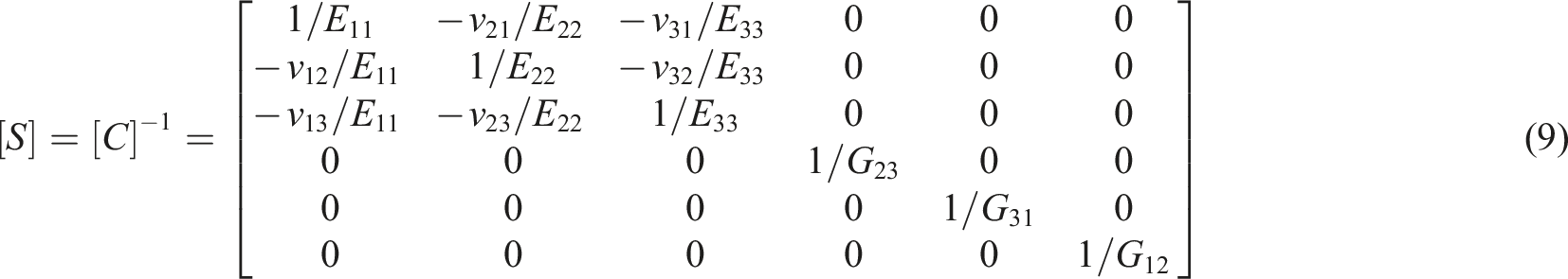
Construction of representative volume elements
Referring to the Micro-CT scan of Meng et al., 20 it can be seen that NP-C/C has obvious layered structure and periodic reproducibility, which can be divided into three sub-regions: unidirectional fiber bundle (or called non-woven cloth), short-chopped fiber felt and needling fiber. Unidirectional fiber bundles are regarded as Unidirectional (UD) composite, short-chopped fiber felt is regarded as Short Fiber Reinforced Composite (SFRP), the properties of needling fibers are simplified to be same as unidirectional fiber bundles.
The multiscale finite element model established in this paper includes three cubic Micro-RVE and one laminate Meso-RVE. When the edge length of the micromechanical model is in the range of 100–500 μm, the influence of porosity on the matrix can be effectively analyzed;
9
Based on this, a Micro-RVE with a side length of 100 μm is established to describe the porous matrix. The preliminary analysis of the RVE size by Melro et al.
26
proposed that the results of the finite element model tend to converge when the RVE side length is greater than 10 times the fiber radius. Since the fiber diameter is considered to be a constant 7 μm, a Micro-RVE with a side length of 35 μm is established to describe UD Composite, and a Micro-RVE with a side length of 100 μm is established to describe SFRP. When the thickness of NP-C/C is less than 10 mm, the needle puncture characteristics of each layer are basically uniform and similar;
27
from this, Meso-RVE containing a needling fiber is established, the side length of which is defined as 9.08 mm,
18
which was sufficient to capture the characteristics produced by the needle and could reduce the computational cost. Using the sequential multiscale method, the mechanical properties of Mico-RVE are transferred upward to Meso-RVE and to Macro-Sample, as shown in Figure 1. Multiscale model construction and analytical homogenization methods of NP-C/C (Reprinted from [20]. with copyright permission from Elsevier).
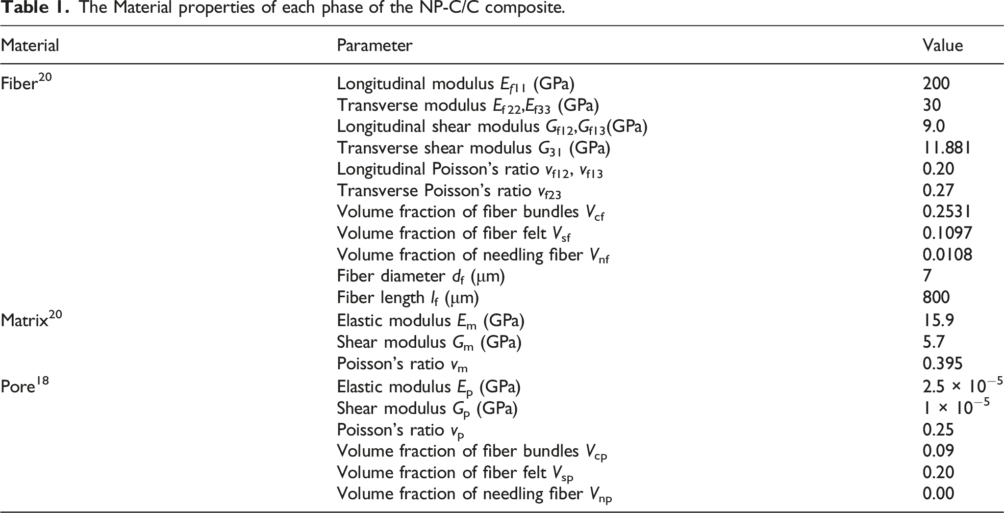
The Material properties of each phase of the NP-C/C composite.
Micro-RVE homogenization of porous matrix
The porous matrix can be regarded as ellipsoid inclusion problem after simplification,
9
where the pores are arbitrarily oriented in spatial position and angle, so the equivalent matrix can be considered as an isotropic material. This section also calculates the modulus of equivalent matrix referring to the Mori-Tanaka method
22
shown by formula (1).
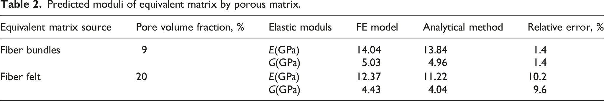
Predicted moduli of equivalent matrix by porous matrix.
Micro-RVE homogenization of unidirectional fiber bundles
The homogenization of the fiber bundle lies in its equivalence with the transverse isotropic material. According to the stiffness matrix form, the periodic strain is first applied to the Micro-RVE to calculate its stress situation. Then, the stress-strain equation is solved, the equivalent stiffness coefficient is obtained, and the stiffness matrix calculation of the homogenized layer is completed. Finally, the stress and strain differential elements of a single fiber or matrix can be derived by formula (2):
Continue to homogenize the fiber bundles using the Chamis empirical formula,
24
shown as formula (3). The properties of UD composites are affected by fiber shape, arrangement and load form, that is, there is a Hashin-Shtrikman boundary
21
in the elastic modulus; the principle of minimum potential energy gives the upper limit of Voigt and the principle of minimum residual energy gives the lower limit of Reuss. The accuracy of predicting the longitudinal modulus (E11 and G12) of UD composites by using the Chamis empirical formula is high, but the prediction accuracy of the transverse modulus (E33 and G23) needs to be further judged according to Micro-RVE.
Referring to random UD composites,
28
regular UD composites is established for comparison. The finite element models under different fiber arrangement and load form are established, and the internal stress distribution under lateral load of UD composites can be obtained, as shown in Figure 2. Stress field diagram of UD composites: (a) Regular;(b)Random; (c)-(d) Transverse tension; (e)-(f) Transverse shear.
Prediced moduli of fiber bundles with literature values.

Micro-RVE homogenization of short-chopped fiber felt
In this section, Halpin-Tsai formula
23
is used to complete the modulus prediction of fiber felt. When giving the fiber length, slenderness ratio and volume fraction, the modulus prediction of unidirectional short fiber composite can be derived using the following:
For fiber felt composed of random short fibers (Considered SFRP), Young’s modulus Es and shear modulus Gs are calculated as formula (5).
Prediced moduli of short-chopped fiber felt with literature values.

The fiber felt is equivalent to the isotropic material to obtain the predicted elastic modulus. Except for the large relative error of the in-plane shear modulus (caused by the different forms of short fiber generation), the relative error of the predicted value of the modulus of fiber felt is within 4%. Since fiber felt is not used as a reinforced phase, the distribution mode of short fiber has little influence on the overall modulus of NP-C/C. The result of Table 4 also shows that, the proposed analytical homogenization method can be used to predict the modulus of fiber felt.
Meso-RVE modulus calculation
Modulus calculation based on finite element model
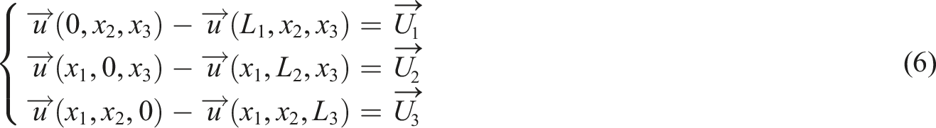
Establishing Meso-RVE with symmetry of structure and load reduces model size and analysis time. However, Meso-RVE is a layered structure, the material properties are not continuous, and the problems of stress discontinuity and strain incoordination are prone to occur during loading, which will lead to deviation when solving the stiffness matrix. To ensure the coordination of deformation under load, we define and apply the periodic boundary conditions.
19
First, periodic strain is applied to the finite element model, equating it with a homogeneous elastomer. Meso-RVE can be regarded as an orthotropic material after homogenization, thus we can derive the stiffness matrix by formula (7).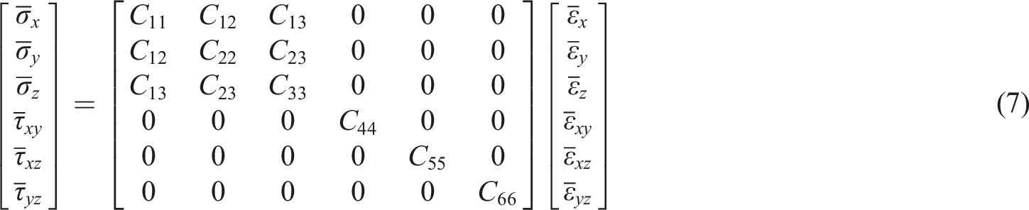
Secondly, the equivalent stiffness coefficient in the loading direction is calculated according to formula (8), and the loading is carried out multiple times according to the number of independent stiffness coefficients until the stiffness matrix is solved. Loads several times according to the strain number to solve all the stiffness coefficients.
Strain case and stiffness coefficient calculations.

According to Figure 3, it can be observed that the model has obvious stress stratification under the in-plane tensile strain(εx and εy), and the fiber bundle in the same direction as the load is used as the reinforced phase. Under shear strain, the stress of each layer is relatively continuous, and there is no obvious reinforced phase. Deformation field and stress field diagram of FE model.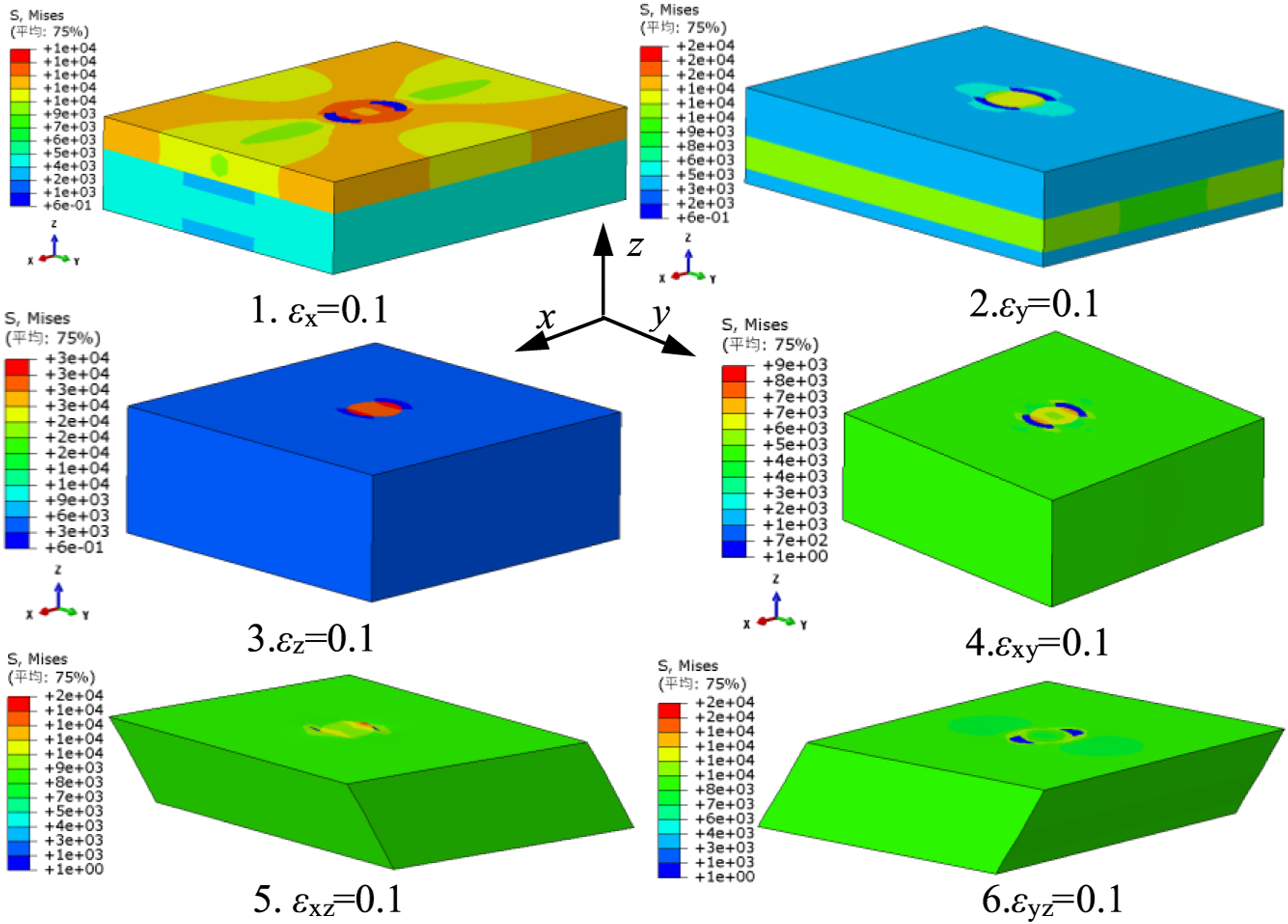
Comparison of measured and predicted values of composite specimens.

Finally, we can draw some important conclusions about the internal stress distribution of the FE model. Taking the x-direction tensile strain (εx = 0.1) as an example, there is an obvious stress concentration at needling fiber, and the xy plane stress field diagram shows a symmetrical distribution at the center, shown in Figure 4(a). The 0° fiber bundle with the same load is used as the reinforced phase, and the 90° fiber bundle carries most of the remaining stresses, and the average stress value σ11 in the fiber direction is three times the average stress value σ22 in the matrix direction (σ11/σ22 = 3.17), as shown in Figure 4(b). Stress field diagram of FE model: (a) In plane direction; (b) Out of face direction. Stress field diagram of interface: (a) Numbering form; (b) Interface-1; (c) Interface-2; (d) Interface-3.

The interface is alternately distributed between the fiber felt and fiber bundle, with three layers and numbered sequentially. The interface is mainly used to describe damage at the contact between two-phase materials, and stiffness values need to be given to ensure deformation coordination and prevent material embedding. This section focuses on predicting the effective modulus of elasticity of NP-C/C, without considering interlaminar damage, so only the interfacial stiffness is assigned to analyze the stress field. According to the research of Vaughan et al., 31 the displacement continuity can be maintained when the interface stiffness is greater than 105 N/mm2. Continue to analyze the interfacial stress of each layer using the x-direction tensile strain as an example (εx = 0.1).
Figure 5 indicates that the maximum stress values of the three interfaces are: Interface 1 is 5.3 MPa, Interface 2 is 1.4 MPa, while Interface 3 is 1.5 MPa; since the 0° fiber bundle is used as the reinforced phase, interface 1 carries the highest stress value. The interfacial stress field diagram is still symmetrically distributed along the center, and the stress concentration area is basically consistent with the direction of the continuous fibers in the fiber bundle. The stress concentration at the interface occurs at the contact between the needling fiber and the fiber bundle, which is consistent with the work of Nie et al., 32 who found that the needle-punched damages caused the failure of the composite.
Modulus calculation based on analytical homogenization method
This section continues to complete the calculation of the modulus based on the analytical homogenization method. Based on the above analysis, three Micro-RVE are established to characterize unidirectional fiber bundles, short-chopped fiber felts, and needling fibers in NP-C/C. Using Meso-RVE as the smallest hierarchical unit of NP-C/C, the layered form shown in Figure 6 is obtained. At the same time, according to the direction and distribution of fiber phase, matrix phase and pore phase, the respective homogenization process is completed. Meso-RVE model: (a) Layered form; (b) Geometric parameters.
where ln is the side length of Meso-RVE, ts is the thickness of the short-chopped fiber felt, tu is the thickness of the unidirectional fiber bundles, and ϕn is the diameter of the needling fiber.
Since the thickness of each layer of NP-C/C is constant, Meso-RVE without needling fibers can be considered laminates. According to the classical laminate theory,
25
the calculation formula for the total stiffness matrix [C]u of fiber bundles under different laying sequences is:
The stiffness matrix of fiber bundle and fiber felt is linearly superimposed according to the layer thickness ratio, and the laminates stiffness matrix [C]L (where [C]L = [S]−1L) is calculated. Because the needling fibers follow the z direction, the laminate flexibility matrix is used to stack linearly with the needling fiber flexibility matrix based on the area ratio. The Meso-RVE flexibility matrix [S]R is calculated, shown as in the Formula (11). The modulus of NP-C/C can be calculated by the classical laminate theory, and the analysis results are shown in Table 6.
Modulus comparison and analysis of needle-punched carbon/carbon composites
Modulus comparison based on analytical method and finite element model
As mentioned earlier, a multiscale finite element model is established and the modulus of NP-C/C is predicted using the analytical homogenization method. According to the distribution mode of fiber, matrix and pores, Micro-RVE and Meso-RVE were selected to establish a multiscale model; and through a series of numerical formula, we complete the analytical homogenization of the micromechanical model.
Geometric parameters of needle-punched carbon/carbon composites.
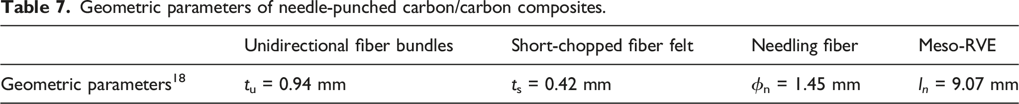
Table 7 indicates that the average errors of the predicted values of stiffness coefficients of the two specimens obtained based on the analytical method are 6.0% and 7.0%, which are lower than the average relative errors of 25.3% and 25.6% of finite element model. The results show that the predicted values of the three stiffness coefficients of the two specimens under the analytical method are in good agreement with the experimental values.
The weight analysis of the influence of each parameter on the modulus
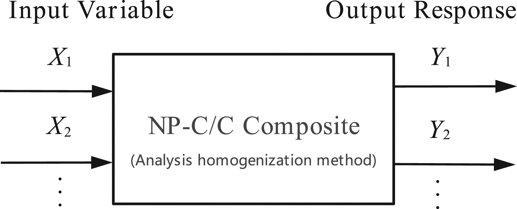
In the previous section, the prediction of NP-C/C modulus was realized based on the analysis homogenization method. In this section, the influence weight of each parameter on the modulus was analyzed by adjusting the structural parameters with the help of MATLAB script. Generally speaking, the parameters that can be adjusted in the manufacturing process are: thickness ratio of fiber felt and fiber bundles (ts/tu), fiber volume content (including Vcf and Vsf), and needling density ρn. In this section, we focus on analyzing the Young’s modulus (E11 and E33) and shear modulus (G12 and G23) of NP-C/C, by characterizing the influence weight of each parameter on the modulus (the total influence is 100%), to provide a reference for the optimization of mechanical properties.
Relying on the Monte Carlo simulation
33
shown in Figure 7, the geometric parameters are used as input variables and entered into the established analytical homogenization method to obtain the output response (modulus of NP-C/C). According to the Ref.
34
, the initial input variable is mutated in a proportion of 10% and re-input to obtain a new output response value; then normalizing the input variables to [-1,1], the model is fitted by the ordinary least squares estimation to obtain the regression coefficient aij, which can be derived using the following estimation formula (12). Schematic diagram of Monte Carlo simulation.

Finally, according to formula (13), each linear regression coefficient aij is converted into the contribution rate Nk of the input variable to the output response, which characterizes the sensitivity of each parameter to the structural response.
Take the traditional [0/w/90/w]n layered specimen 1 as an example, and its structural parameters are shown in Table 7. The initial structural parameters (including: ts/tu, Vcf, Vsf, and ρn) were each subjected to 10% mutation using MATLAB, the contribution rate of each parameter to the NP-C/C modulus is shown in Figure 8. Analysis of the contribution rate of each parameter to the modulus.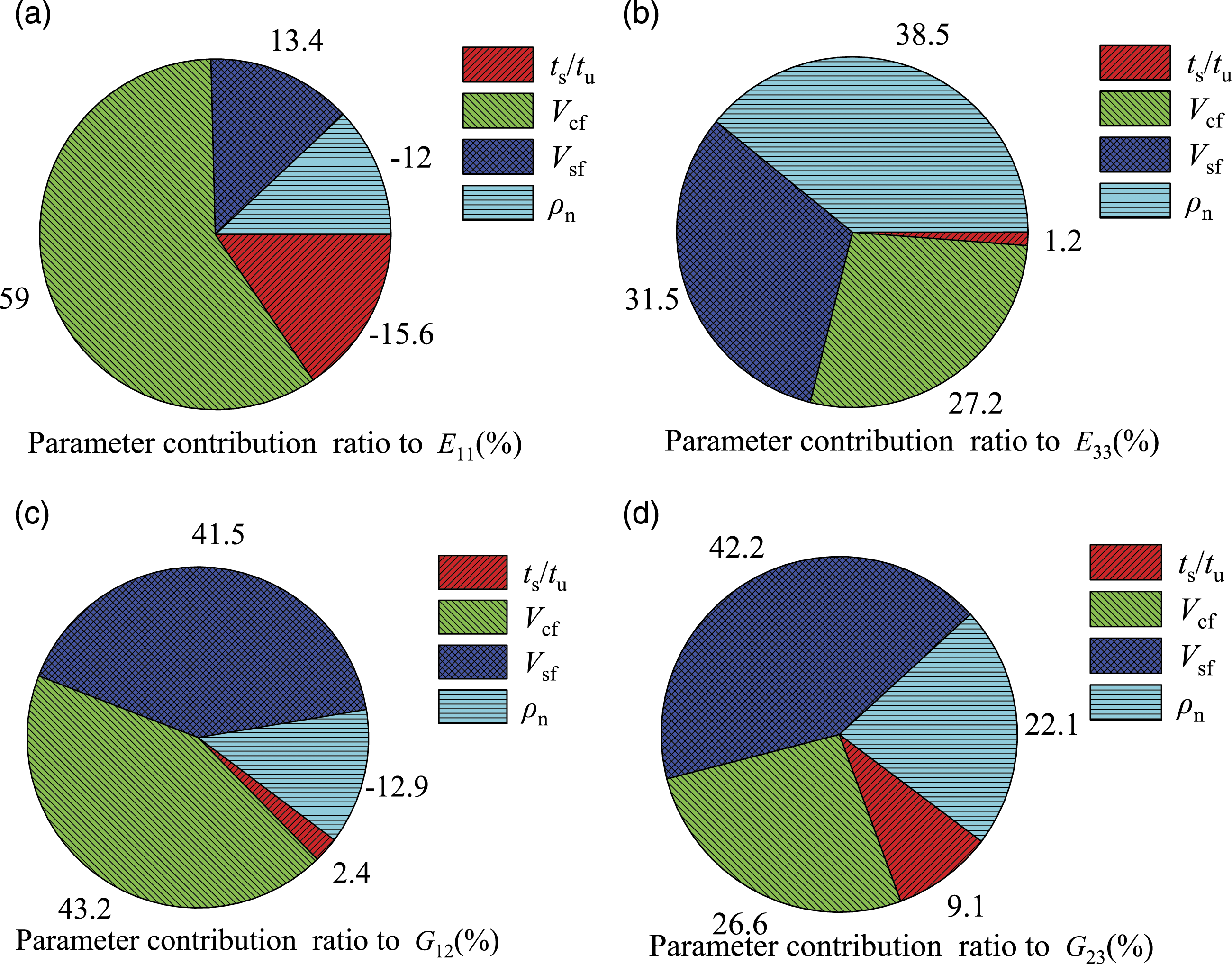
The results show that, increasing the needling density ρn favors the out-of-plane properties (E33 and G23) of NP-C/C, but reduces the in-plane properties (E11 and G12). Fiber volume fractions (including Vcf and Vsf) has the greatest influence weight on the modulus, but the impact is different: Vcf mainly affects the in-plane properties, and Vsf mainly affects the out-of-plane properties. Increasing the fiber volume fraction can significantly improve the modulus in all directions. At the same time, it can be found that the increase of the layer thickness ratio (ts/tu) will reduce the in-plane modulus E11, but the influence weight on the remaining modulus is less than 10%.
Conclusion
In order to better predict the modulus of Needle-punched Carbon/Carbon composites, this paper complete modulus prediction based on the multiscale finite element model, and carefully analyze the influence of each parameter on the modulus by employing the analytical homogenization method and the MATLAB script. The research shows that, the analysis homogenization method used in this paper can directly program all numerical equations into a single computer script without modeling, and we can realize geometric parameter adjustment through Monte Carlo simulation, which simplifies the complexity of model construction and even enables structural optimization. The relevant conclusions of the study are as follows: (1) The modulus prediction value of NP-C/C based on the analytical homogenization method is in good agreement with the experimental value; the average errors of the predicted values of stiffness coefficient and the experimental values are 6.0%, which are lower than 25.3% of the finite element model. (2) Increasing the needling density ρn is beneficial to improve the (positively correlated) out-of-plane properties of NP-C/C (E33 and G23), but will reduce the (negatively correlated) in-plane properties of NP-C/C (E11 and G12). (3) Fiber volume fraction (including Vcf and Vsf) has the greatest influence weight on NP-C/C modulus, but Vcf mainly affects the in-plane properties, and Vsf mainly affects the out-of-plane properties. Increasing the fiber volume fraction can significantly improve the modulus of NP-C/C in all directions.
Footnotes
Declaration of conflicting interests
The author(s) declared no potential conflicts of interest with respect to the research, authorship, and/or publication of this article.
Funding
The author(s) received no financial support for the research, authorship, and/or publication of this article.