
Abstract
Acoustic radiation through a system of double-walled shells, lined with porous foams, and stiffened by annular plates simultaneously is studied. Based on modeling, the porous foams as absorbent fluid property, acoustic characteristics of structure are presented for various sandwich construction by means of vibro-acoustic finite element method with automatic matching layer technology. It is noted that equipping porous foams and annular plates simultaneously enhances the acoustic insulation of structure in the entire frequency domain. The overall sound power level is modified by the density of shell. Moreover, the increase of structural stiffness is shown to effectively reduce the acoustic radiation via rising the thickness of inner shell and the number of annular plates. The foam cores decrease the peak value of structural sound power level through using polyurethane foam cores and increasing filling ratio.
Introduction
Interior noise and vibration abatement have become one of the main concerns in many fields of industry involving aerospace, submarine, machinery, etc. Noise and vibration can induce negative effects both on person and precision instruments.1,2 Indeed, the utilization of sandwich systems with stiffeners such as annular plates is recognized as one of the procedures, while the major aim is to reduce structural vibration that radiates the acoustic. Besides, the addition of high damping power cores or absorbing foam cores into the system modifies the loss factor and dynamic specifications of the construction. Therefore, reliable prediction of acoustic properties for double-walled shell is of great necessity. Accordingly, the sound power level (SWL) and overall sound power level (OSWL) of a sandwich shell system equipped with annular plates and porous foam cores simultaneously, are investigated in this study.
Much attention has been paid to the vibro-acoustic analysis of sandwich shell structures by means of numerical analysis, experiment, and simulated analysis. Laulagnet and Guyader 3 investigated acoustic radiation from a finite stiffened cylindrical shell by means of the modal superposition. The effects of the stiffeners on vibro-acoustic behavior of cylindrical shells are discussed that ring stiffeners will have a strong influence on phenomena controlled by high circumferential order modes and a weak influence on those controlled by low circumferential order modes. Lee et al. 4 investigated the sound transmission through single and double-walled cylindrical shells by combining the solutions of two different models of the system which is described by acoustic wave equations and Lover’s theory of the thin shell vibration. Differently, Chen et al.,5–8 on the basis of Flügge equation of thin shell and Helmholtz equation, inspected the radiated power and radiation efficiency of finite stiffened double cylindrical shells. It is concluded that the inner shell is the main path to transfer vibration and radiate sound. Efimtsov and Lazarev9,10 developed an effective method on the basis of the space harmonic expansion to predict the vibro-acoustic characteristic of an orthogonally stiffened cylindrical shell. By employing shear deformation shallow shell theory, Rahmatnezhad et al. 11 proposed an analytical strategy to acoustically determine the vibration response of a doubly curved composite shell in a thermal environment while Zarastvand et al. 12 studied the acoustic performance of doubly curved composite shells with stiffeners. Moreover, considering the main aim of enhancing the structural acoustic characteristic by decreasing the vibration and noise of the construction, some damping materials and sound absorption materials are embedded into the double-walled cylindrical shells. Chen et al. 13 employed three-dimensional Navier equations to describe the viscoelastic layer while Hasan et al. 14 used Zener mathematical model. Liu et al. 15 conducted an experiment to study the effect of damping material on vibro-acoustic performance of doubly shell. With porous material, Wu et al., 16 using a combination of the wave number domain approach and the transfer matrix method, developed a theoretical model to predict the far field sound radiation from a finite fluid-filled/submerged cylindrical thin shell. Zhou et al. adopted Biot’s theory to investigate the sound transmission through double-walled cylindrical shells lined with porous material when the structures are excited by an external plane wave 17 or the turbulent boundary layer. 18 Based on the first-order shear deformation theory, Darvish et al. 19 adopted the Biot’s theory to depict the porous core while Li et al. 20 considered the equivalent Young’s, shear moduli and density. Zarstvand et al. 21 introduced Hamilton’s principle with Biot’s study to analyze wave propagation through a porous core. Thongchom et al. 22 conjugated with nonlocal strain gradient theory (NSGT) with the aid of Hamilton’s variational principle to analyze the sound transmission loss of functionally graded sandwich cylindrical nanoshell.
The literatures above theoretically present the improvement of acoustic insulation via various structural materials, employing stiffeners and filling with damping or sound-absorbing materials. Nevertheless, there is no published paper on sound insulation of a doubly cylindrical shells equipped with annular plates and sound-absorbing materials simultaneously. It is still attractive that how does the double-walled shells radiate acoustic both with stiffeners and sound-absorbing materials. Admittedly, theoretical analysis is available for the relatively simple geometrical structure with some ideal assumptions but when it comes to realistic problems with complicated structure and condition, as the considered construction, the analytical solutions will be extremely difficult to obtain. In this framework, various numerical techniques have been proposed to cope with the problems of acoustic radiation in the context of the rapid development of computer science. Among them, the classical boundary element method (BEM)
23
and finite element method (FEM)
24
are two most powerful and versatile numerical approaches to tackle the acoustic problems. Compared to FEM requiring the discretization of the whole zone of the problem, only the boundary of the problem needs to be discretized in BEM, causing the reduction of model sizes and subsequent computational efforts. Nevertheless, the system matrices generated by the BEM model are usually non-symmetric and dense. Besides, the BEM impose restrictions on the ability of handling the exterior acoustic problem in nonisotropic and nonhomogeneous media. In these cases, a novel singular boundary method (SBM)25,26 was proposed to handle the acoustic problems while Fahmy et al.27–35 optimized the algorithm to reduce the computational complexity and computational time and to overcome some nonlinear problems. These methods contribute to solving singular or hypersingular integrals, but much of the research is focused on future-proofing the method and higher resolutions of elements is continually desired, particularly as this is necessary for modeling high frequency problems.
36
As an effective alternative discretization technique, FEM is derived from the variational principle and the weighted residual concept. It can perform the coupling with complicated structures naturally and can handle the problems in the nonisotropic and nonhomogeneous media.37–39 Rawat et al.
40
employed a coupled acoustic-structural FEM for fluid-structure interaction (FSI). Additionally, the exterior acoustic problems are well solved by using FEM with artificial boundary surface involving Dirichlet-to-Neumann (DtN) map,
41
the perfect matched layer (PML),
42
the absorbing boundary conditions,
43
and so on. Due to the huge model size and cumbersome solution steps, the automatically matched layer (AML)44–47 is proposed to obtain accurate layer retaining the ease of implementation in existing codes. Therefore, based on these discretization techniques, various mature software such as ANSYS, COMSOL, Abaqus, and LMS SYSNOISE have been developed to study the sound radiation responses of mechanically excited isotropic flat panels with uniform
48
and varying thickness
49
and cylindrical shells with porous foam.50, 51 Noteworthily, LMS SYSNOISE, an advanced software for vibro-acoustic design and structure optimization, is capable of analyzing the acoustic radiation from vibration source and computing radiation sound field of structural surface or any point requested. In addition to employing sound pressure (SP), sound power (SW) is adopted to inspect the acoustic radiation performance of structure. SW with the following formula is the total acoustic energy emitted by a source which produces sound pressure at some distance per unit time.

To intuitively reflect the acoustic radiation performance of the structure, sound power level (SWL) is employed.

The SWL of a source is fixed while the SPL depends upon the distance from the source and the acoustic characteristics of the area in which it is located. Therefore, it is more appropriated to describe the structural acoustic radiation performance with SWL rather than sound pressure level (SPL). Besides, for the purpose of investigating the overall acoustic feature of considered structure in the entire frequency domain, overall sound power level (OSWL) is introduced in LMS SYSNOISE. Meanwhile, the simulation accuracy and computational efficiency are improved via a constant introduction of advanced mathematical methods. Hence, it is probable to develop an accurate and efficient model for investigating the acoustic performance of a double-walled shell employed annular plates and foam cores contemporaneously.
This article is structured as follows. Coupling theory of FE model with AML technique and the effect of structural parameters on acoustic insulation are proposed in the section of Numerical results and discussion. The discussions of various parameters are concluded in the section of Conclusions. Besides, geometry dimensions and simulation coefficient for FE model are provided in appendix 1 and appendix 2.
Numerical results and discussion
Formulation of the problem
This work is trying to overcome the acoustic radiation problem of a doubly cylindrical shell system in practical engineering when vibrated by a harmonic force in the air. As illustrated in Figure 1(a), the considered structure in this study is composed of a free double-walled cylindrical shell manufactured of aluminum material, which equips the annular plates and is subjected to several polyurethane foam cores. Besides, the cylindrical shell is closed by wooden plates at two ends to satisfy the practical engineering condition and excited by a unit harmonic force in the middle of the inner shell to indicate the excitation at the cylindrical shell by machines inside the shell. Furthermore, the interior acoustic field and the exterior acoustic filed is given in Figure 1(a) to represent the air domains. (a) Configurations of double-walled cylindrical shells equipped with annular plates and polyurethane foam cores in acoustic field. (b) Computational domains both for interior and exterior acoustic problems. (c) Schematic comparison of PML method and AML method.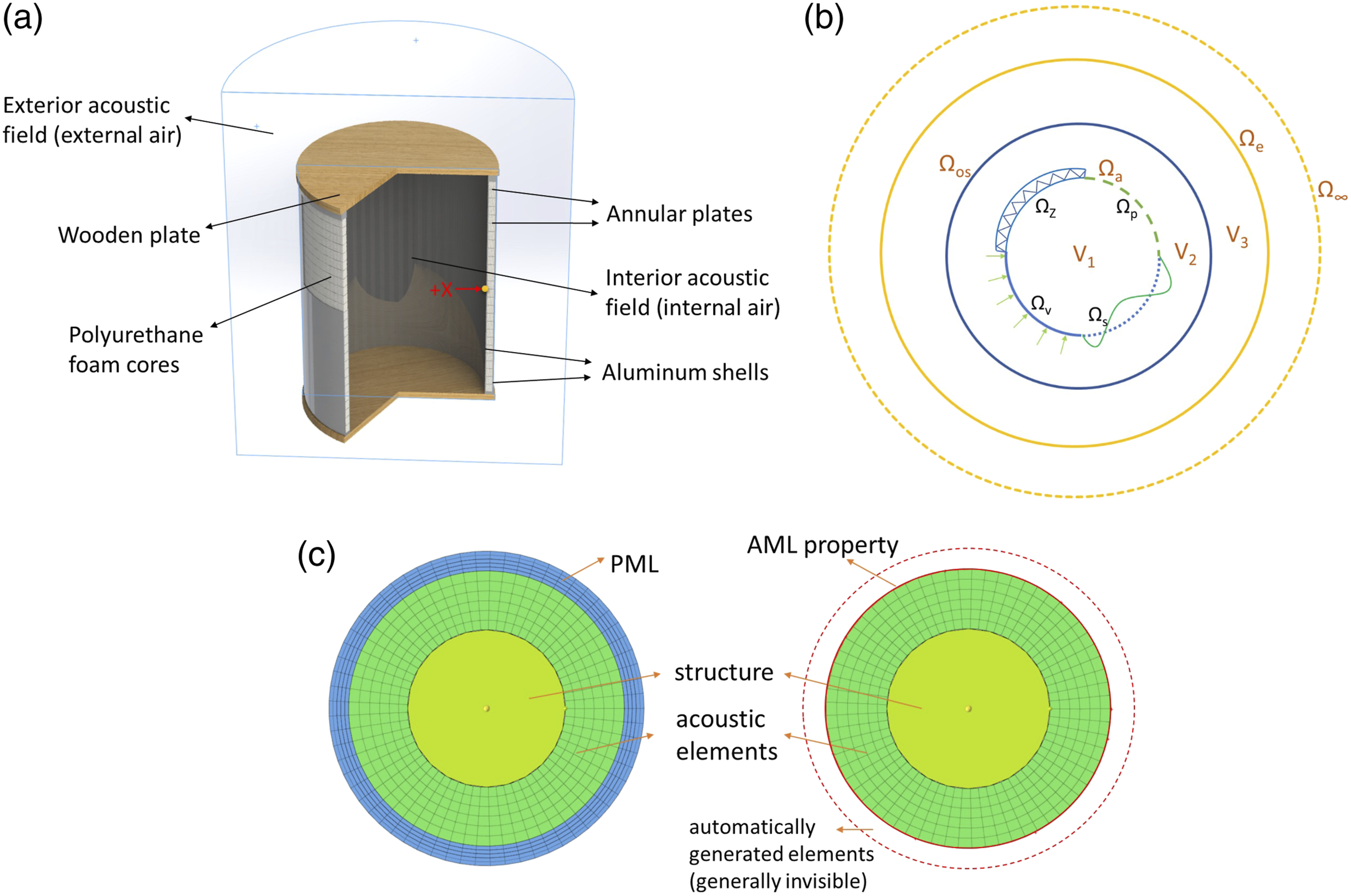
Numerical implementation of the FE model
For coupled vibro-acoustic problems, an acoustic and a structural problem must be solved simultaneously to include the mutual coupling interaction between the fluid pressure and the structural deformation.
Interior coupled vibro-acoustic system
In an interior coupled vibro-acoustic system, the fluid is comprised in a bounded acoustic domain V1, of which the boundary surface Ωa contains an elastic structural surface Ωs, an acoustic pressure boundary Ωp, a normal velocity boundary Ωv and a normal impedance boundary ΩZ (Ωa = Ωs ∪ Ωp ∪ Ωv ∪ ΩZ), as shown in Figure 1(b). One acoustic boundary condition is specified at each position on the closed boundary surface Ωa:
Imposed pressure

Imposed normal velocity

Imposed normal impedance

Normal velocity continuity

The last boundary condition expresses the vibro-acoustic coupling condition, in that the normal velocity must equal the normal structural velocity along the fluid-structure coupling interface Ωs.
Acoustic FE model
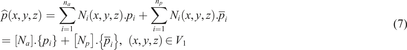
The finite element approximation of the steady-state pressure p in the bounded fluid domain V1 is an expansion

The (nax1) vector {F
a
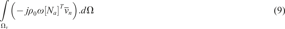
} contains the terms in the constrained degrees of freedom, the contributions from the external acoustic sources in the fluid domain V1, and the contributions from the prescribed velocity input, imposed on part Ωv of the boundary surface (equation (2)). The latter contributions are expressed as
Structural FE model
The finite element approximations of the steady-state dynamic displacement components of the middle surface Ωs of an elastic shell structure in the x-, y-, and z-direction of a global Cartesian co-ordinate system are
53
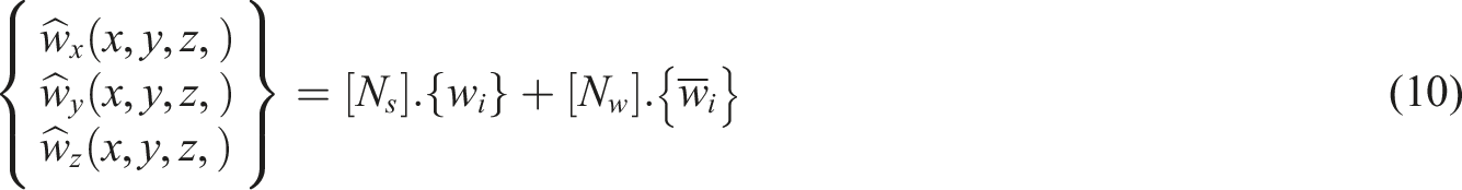
Similar to the acoustic finite element model for unconstrained degrees of freedom, the structural one takes the form


Coupling of both models
The force loading of the acoustic pressure on the elastic shell structure along the fluid-structure coupling interface in an interior coupled vibro-acoustic system may be regarded as an additional normal load. As a result, an additional term of type (equation (10)), using the acoustic pressure approximation (equation (5)), must be added to the structural FE model (equation (9)). When it is assumed that the elastic shell structure is completely comprised in the boundary surface of the fluid domain, the structural FE model (equation (9)) modifies to

The (nsxna) coupling matrix
and the (nsx1) excitation vector

The continuity of the normal shell velocities and the normal fluid velocities at the fluid-structure coupling interface may be regarded as an additional velocity input on the part Ωs of the boundary surface of the acoustic domain. As a result, an additional term of type (equation (7)), using the shell displacement approximations (equation (8)), must be added to the acoustic FE model (equation (6)). This modified acoustic FE model becomes

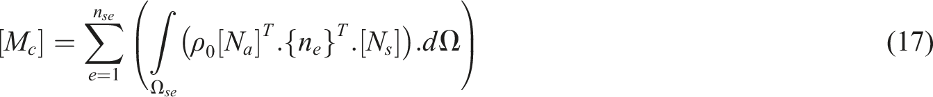
The (naxns) coupling matrix [Mc] is
and the (nax1) excitation vector

A comparison between the coupling matrices equation (12) and equation (15) indicates that

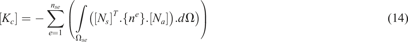
Combining the modified structural FE model (equation (11)) and the modified acoustic FE model (equation (14)) yields the Eulerian FE/FE model for an interior coupled vibro-acoustic system

Exterior acoustic radiation system
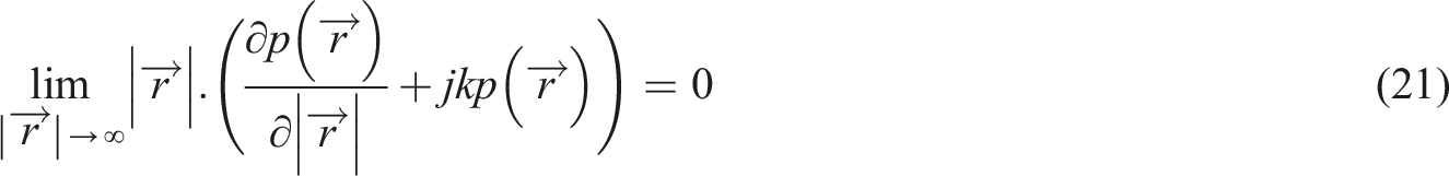
For exterior acoustic problems, the Sommerfeld radiation condition must be satisfied at the boundary surface Ω∞ to ensure that all acoustic waves propagate freely towards infinity and that no reflections occur at this boundary
In principle, the finite element method can only be used for interior acoustic problems, which have a bounded acoustic domain, since the numerical implementation requires a finite number of finite elements. In this framework, in order to solve such problems involving spatially unbounded domains in FEM, an artificial absorbing boundary or layer, which is called the perfectly matched layer (PML), is introduced at some distance from the outer shell Ωos achieving a bounded computational domain V3 between Ωos and Ωe (see Figure 1(b)). The perfectly matched layer (PML) approach is an advanced approach which consists of using “damping” elements at the artificial boundary surface of the finite element discretization of domain V3 in order to approximately model the absorption of outgoing acoustic waves regardless of their frequency and angle of incidence (see Figure 1(c)). Note that the prediction accuracy obtained from the PML approach, depends on the thickness of artificial-meshed “damping” elements, so that the PML is supposed to contain 4–5 layers of “damping” elements, of which the total thickness satisfies

In this framework, with the same principle as PML approach, the acoustic institution of LMS SNSNOISE develops the automatic matching layer (AML) technology where the absorbing layers and absorbing coefficient are mechanically defined by the physical model and the computational frequency (see Figure 1(c)). Thus, the prediction accuracy depended on the absorbing elements improves with the reduction of computational efforts. By employing SYSNOISE with the coupling FEM, FE models for the considered structures are developed in a similar mode where the cylindrical shells and the annular plates are set as structural mesh part with the description of shell elements while the air fields represented by solid elements, that is, inner acoustic field and exterior acoustic field, are considered as acoustic mesh part. Besides, the porous forms cores with absorbent fluid property are also set as acoustical mesh part. The coupling surface is specified at the interaction boundary between structure parts and acoustical parts accounting for the vibro-acoustic coupling.
Validation of FE model
As a matter of fact, this FE approach has been adopted in investigating the acoustic performance of single cylindrical shell with melamine foam
54
in mid-low frequency zone. Figure 2(a) and (b) illustrate that the differences of overall SPL between simulation and test are only 1.9% and 1.6%, respectively, which verifies the correctness of the finite element model. Moreover, in order to check the computational accuracy of FE model further, the sound pressure level spectrum is employed to propose the comparison with the same material and geometrical properties of the work studied by Jiang,
55
as presented in Figure 2(e). In his investigation, the acoustic radiation of an underwater double-walled cylindrical shells closed by plates at two ends to ensure the water tightness of the model is analyzed, where the inner shell is welded with its outer shell by annular plates. The specific parameters, including material properties and geometry dimensions of the model, are shown in Appendix 1. To validate the results, a FE model with structural elements and acoustic elements is presented in Figure 2(c)–(d), where the elements of inner shell are connected to the outer shell by welding nodes on the elements of annular plates. In addition, force with the magnitude of 20N is applied inside the shell to represent the excitation of shaker at the structure and the data field point is created 1.25 m away from the excitation point along the radial direction. Based on the obtained outcomes, it is observed that there are differences at some peak and dip points which may be attributed to the constraints that the underwater construction is hung during the experiment while free in numerical analysis. Besides, towards the water tightness of the model, Jiang utilized the rubber pads and bolts to seal the plates at each end while it is simplified in FE model, which may yield the disparity between numerical result and experimental data. However, in addition to the acceptably subtle deviation mentioned, the sound pressure level (SPL) spectrum curve of FE model coincides with the curve of underwater experiment which confirms the accuracy of present method. Comparisons of FE model and experiment of the cavity response without MF lining (a) and with 40 mm MF lining (b). Finite element model of structure (c) and acoustic-structure coupling (d) for Jiang. (e) Comparison of sound pressure level measured by Jiang (the purple line) and numerically computed with current method (the orange line).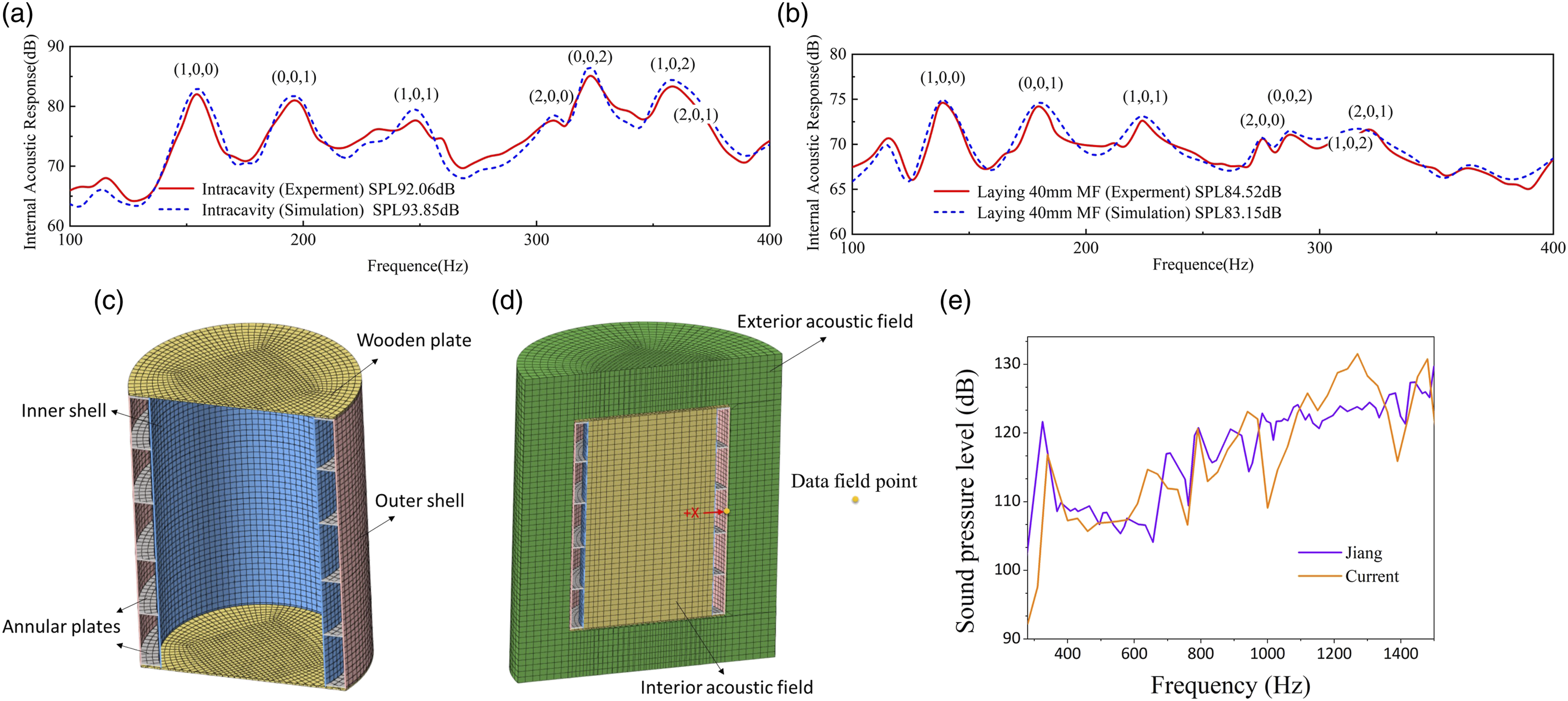
Effects of sandwich structure on SWL
The sandwich structure is a key geometry factor to specify the acoustic radiation performance of the double-walled cylindrical shells. The importance of this subject is shown in Figure 3(d). The results of this configuration can be effective in the design process of the cylindrical shell constructions. To achieve the results, as presented in Figures 3(a)–4(c), three kinds of sandwich structures including structure Sa only equipped with annular plates, structure Sb only with polyurethane foam core, and structure Sc with annular plates and foam cores in the gap of the annular plates simultaneously, are designed with the same geometrical and material parameters of the structure. The specific parameters are given in Appendix 2. According to the zoom shot at the frequency range of 1 Hz–90 Hz, the SWL of structure Sb is higher than structure Sa and structure Sc while structure Sc is equal to structure Sa, which shows the positive effect of annular plate and little effect of polyurethane foam on acoustic insulation at low frequency. Besides, it is noteworthy that comparing to the other two structures in the entire frequency zone, structure Sc wins the best acoustic feature with the lowest overall sound power level (OSWL) of 65.27 dB, which can be interpreted in two ways. On the one hand, it is due to the fact that the annular plates welding the inner shell to the outer shell stiffen the cylindrical shell, which generates the remarkable increase of flexural and torsional stiffness of structure and the reduction of acoustic radiation. This alteration yields the enhancement of natural frequency that moves from 110.5 Hz to 310 Hz, as shown in the comparison of SWL between structure Sc (purple line) and structure Sb (orange line), where the SWL peaks of structure Sc moves to higher frequency. On the other hand, polyurethane foam core is adopted to absorb the sound by converting the sound energy into heat energy instead of modifying the stiffness of the structure. Compared to the SWL spectra of structure Sa (blue line), structure Sc (purple line) appears in the same tendency with lower peak values. Structure Sa with annular plates (a), structure Sb with porous foam core (b), and structure Sc with both annular plates and porous foam core (c). (d) Comparison of sound power level among Sa (in blue), Sb (in orange), and Sc (in purple) with OSWL.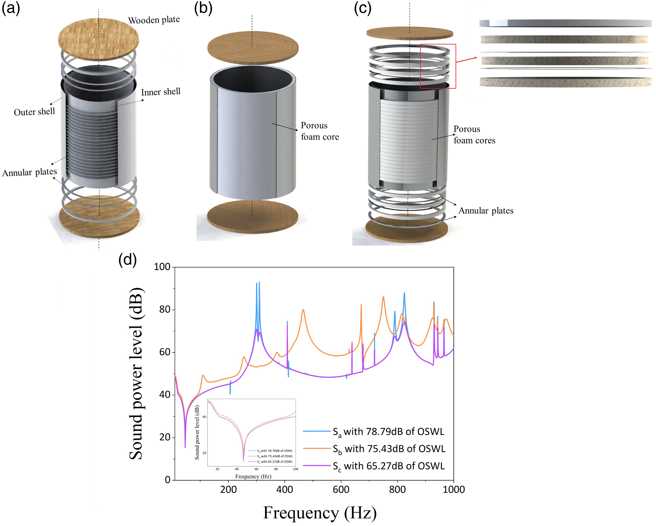
Effects of structural properties on SWL
The results in section 2.3 demonstrate that structure Sc performs the best in suppressing acoustic radiation. Based on this structure, various structural properties involving the material of shells, the thickness of shells and annular plates, and the number of annular plates are employed to explore the impact on acoustic insulation.
Figure 4(a) checks the influence of material properties including density, elastic modulus, and Poisson’s ratio. Accordingly, with the increase of density, the peak of the SWL moves to the lower frequency and the corresponding value decreases at frequency domains lower than 560 Hz while increases at higher frequency. Because the acoustic performance at low frequency zone is dominated by the quality of the structure which imports that the use of dense materials can effectively reduce the acoustic radiation of the structure at low frequency domains. Additionally, it is noteworthy that the OSWL first decrease and then increase with the enhancement of structural density, which indicates the limitation of acoustic insulation affected by structural quality. Differently, the SWL spectrum is little influenced by the Poisson’s ratio while influenced by the elastic modulus. With the increase of elastic modulus, the peaks of SWL spectra move to higher frequency at the frequency range of 200 Hz–620 Hz, which is contributed to the design process of cylindrical shell. However, it is difficult to modify one of the material properties mentioned and keep the others constant in practical experiments. In this framework, by comparing with aluminum, steel is applied to the cylindrical shell to reveal the strong impact of structural material on acoustic radiation performance. As presented in Figure 4(b), the OSWL of steel is reduced by 2.5 dB with the comparison to that of aluminum, which is due to the lager density and elastic modulus. Although adopting the steel can effectively reduce the acoustic radiation of the structure, it increases the weight which may work against to some practical applications required portability. Therefore, structural material should be employed by specific requirements to achieve the corresponding aims. The sound power level of structure Sc with the variations of material property (a) and material category (b) of the shell.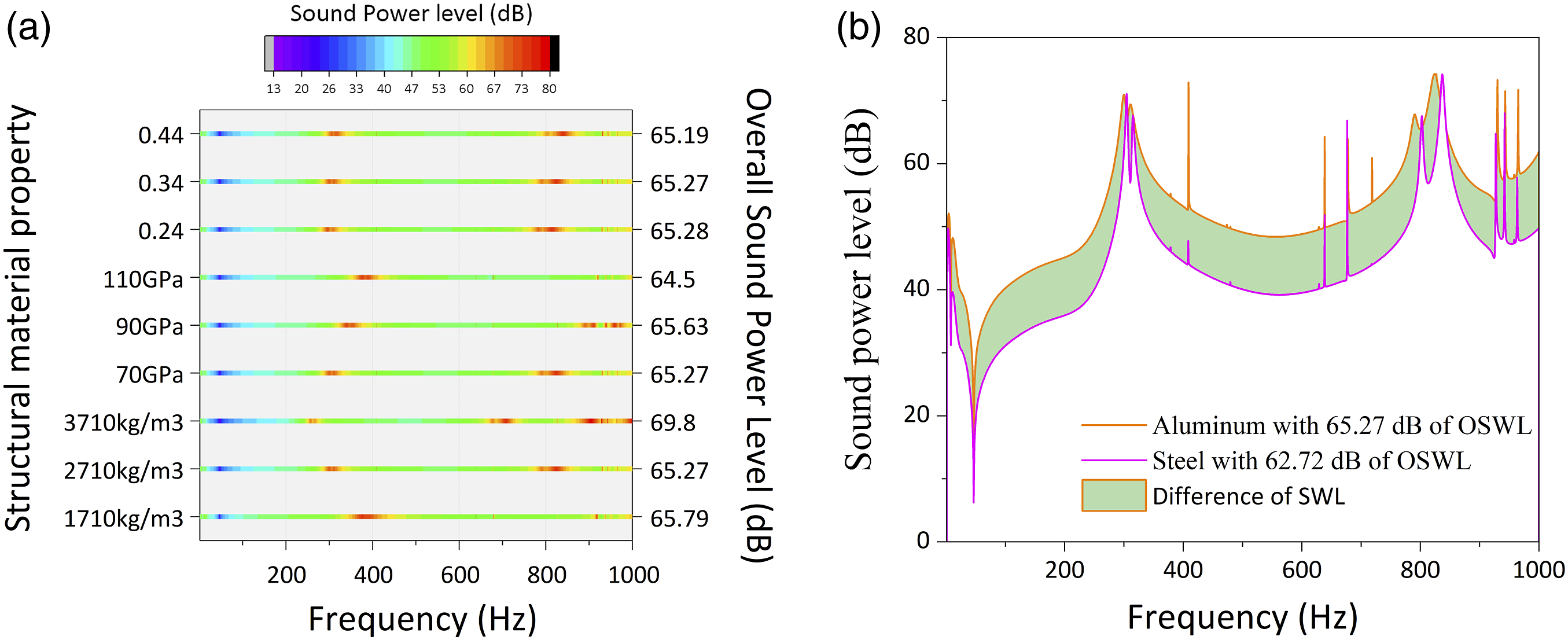
In Figure 5(a)–(c), acoustic responses of double-walled cylindrical shells are analyzed via thickness variation of the shells and annular plates. Accordingly, the SWL curves with the peaks moving to higher frequency are observed in a similar trend via comparing among the thickness variation of inner shell, outer shell and annular plates. Besides, the OSWL of structure with thicker components appears in lower level in entire range of frequency, which is attributed to the enhancement of structural mechanical impedance. Bearing a resemblance to the employment of annular plates, the increase of structural thickness improves the stiffness of structure, which brings the OSWL down and restrains the acoustic radiation. Moreover, the results in Figures 5(a)–6(c) also confirm that as the main aim to improve the acoustic characteristics, focusing on the variations of the inner shell is more effective than the variations of outer shell and annular plates. To further explore the effect of structural factor on acoustic performance, Figure 5(d) illustrates that diverse number of annular plates with 1.6 mm thick of each plate are considered in the doubly cylindrical shells. The outcomes confirm the improvement of structural acoustic performance with the growth of the number of annular plates, which can also be attributed to the increase of structural stiffness. Notably, the annular plates are used to stiffen the double-walled cylindrical shells by welding the inner shell and outer shell, so the stiffness of structure depends on the number of annular plates to some extent. This variation will contribute to the design of double-walled structure. The SPL of structure Sc with the difference in shell geometry parameters including the thickness of the inner shell (a), the thickness of the outer shell (b), the thickness of annular plates (c), and the difference in the number of annular plates (d).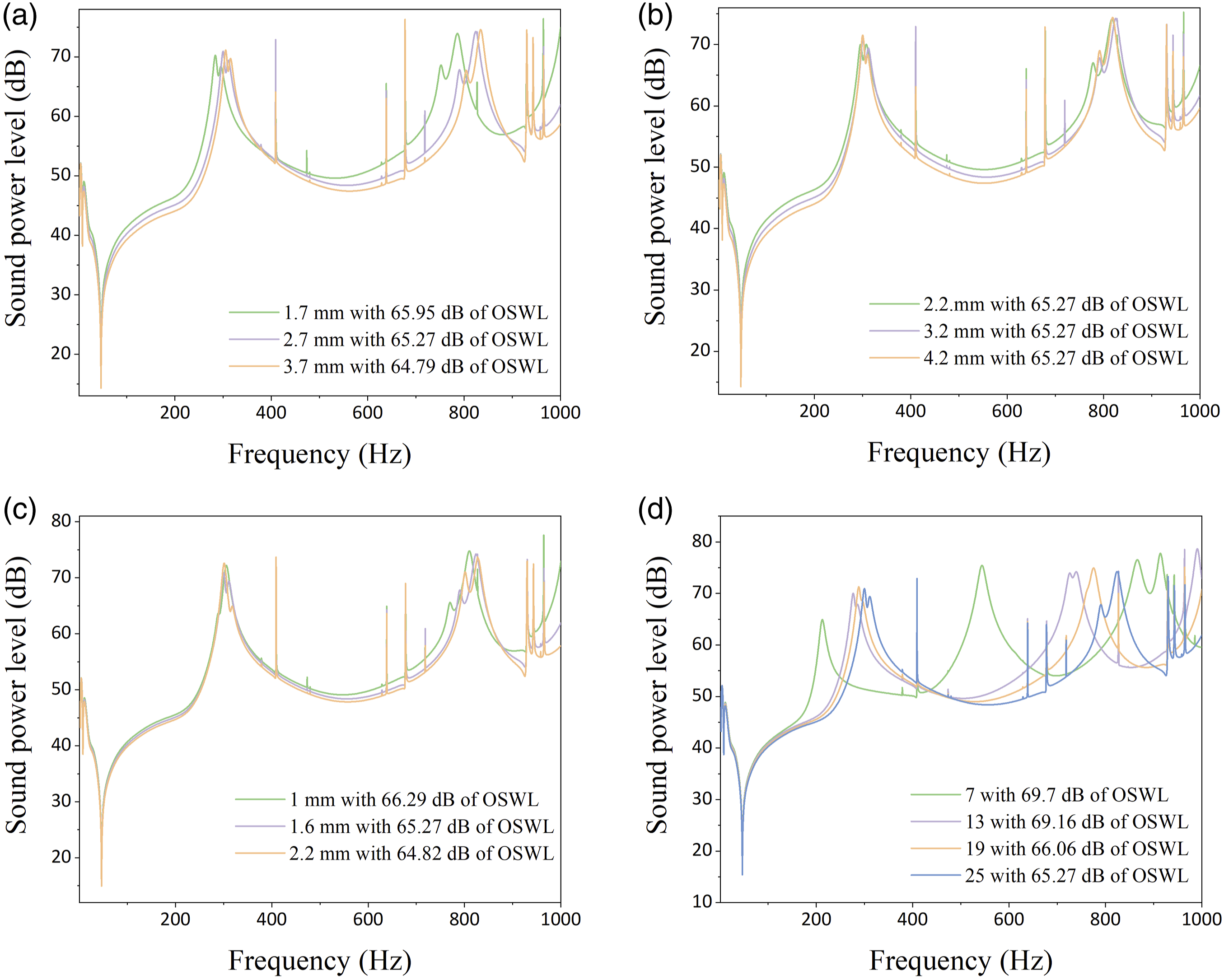
In the cause of investigating the effect of the number of annular plates on acoustic radiation thoroughly, some cloudscapes of SPL of external acoustic field and structural radial displacement of cylindrical shell are presented in Figure 6 at the frequencies corresponding to peaks of SWL. The color distribution of SPL and radial displacement is basically symmetrical, which owes to the symmetrical structure, that is, double-walled cylindrical shells. According to the consequences, the vibration displacements of the shell with amplitude decreasing obviously become relatively uniform during the rise of the number of annular plates. Although the shell with 25 pieces of annular plate acquires the highest SPL at 824 Hz, the displacement amplitude is approaching to that with 19 plates, or even smaller than that with 13 plates. The increase of the number of annular plates improves the structural stiffness, which reduces the vibration displacements of the shell. Hence, the structure could vibrate slightly even at the high level of sound pressure. Cloudscapes of the sound pressure of the external acoustic field and the radial displacement of the shell at the frequencies corresponding to peak values.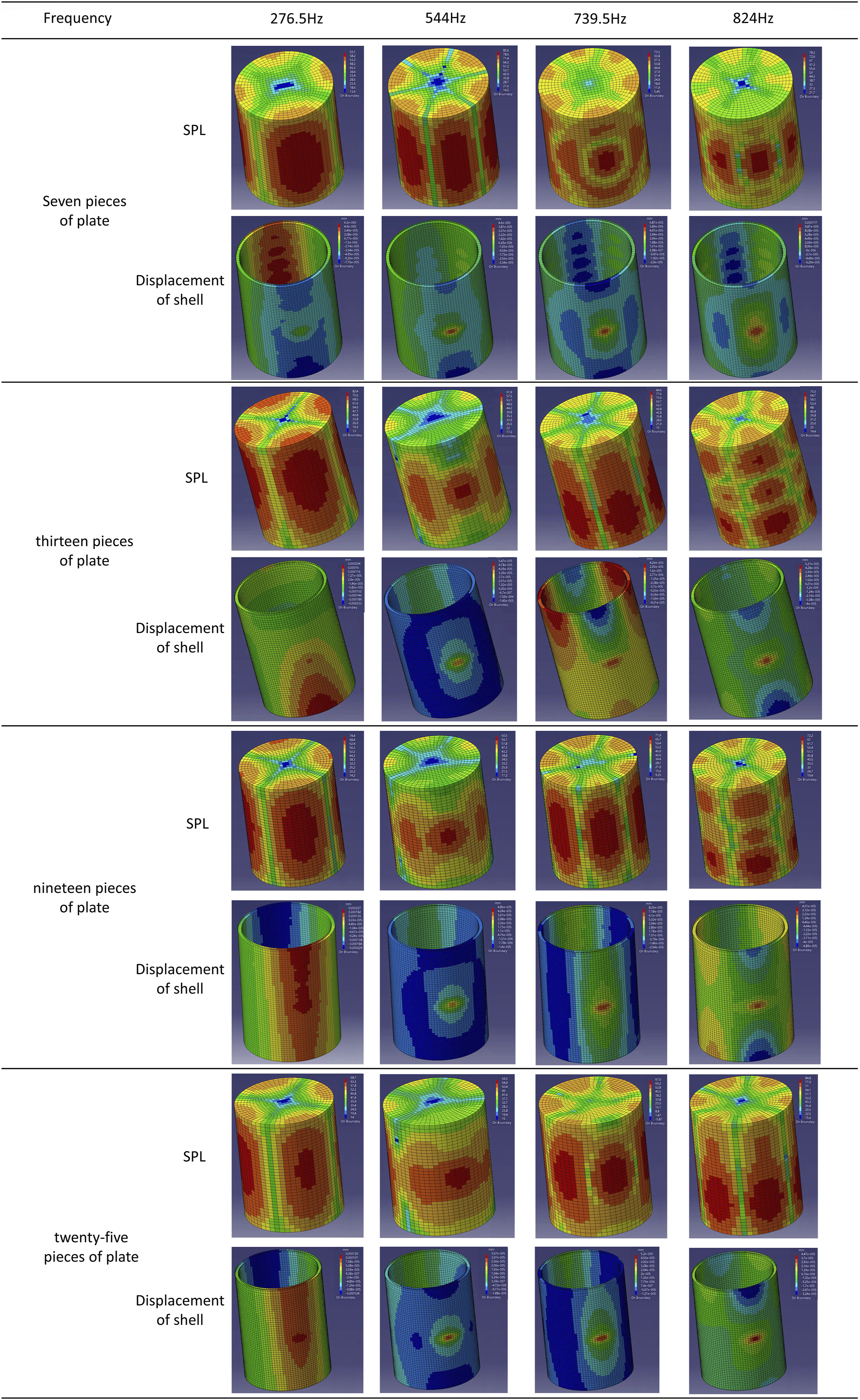
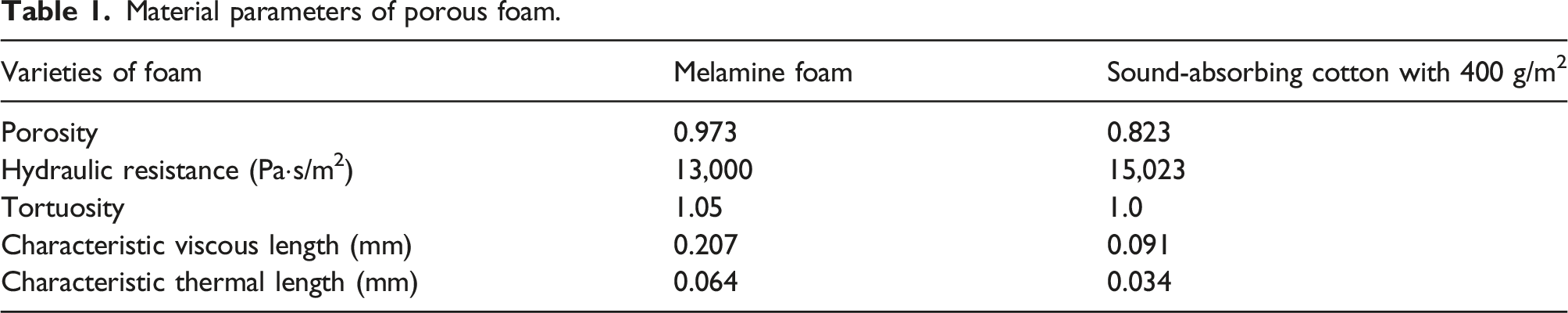
Effects of porous foam core on SWL
Material parameters of porous foam.
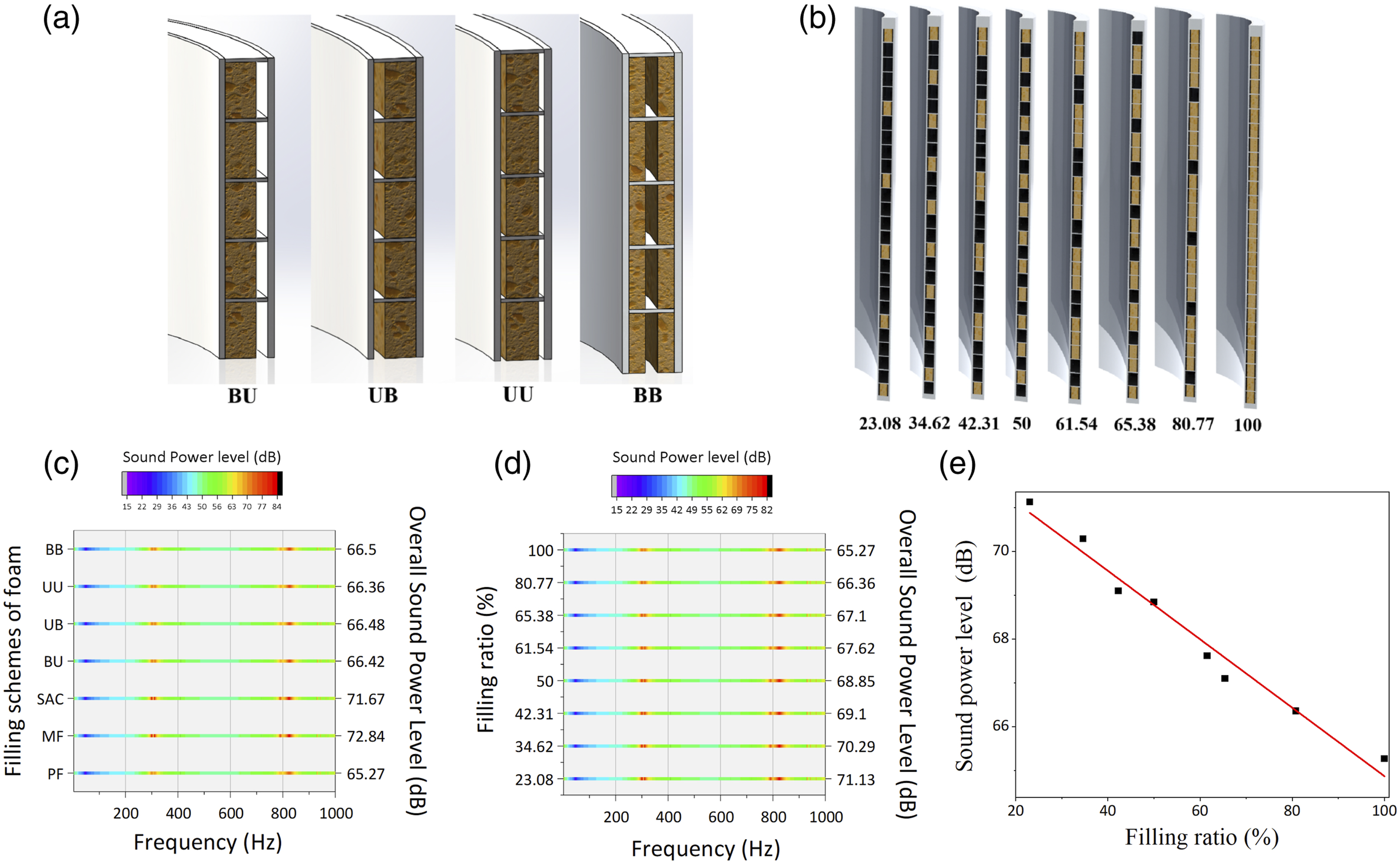
The sandwich structure with different filling schemes of the porous lining inside the cylindrical shell (a) and different porous foam filling ratios (b). The sound power level of the double-walled cylindrical shell with different filling schemes of the porous core (c) and different porous foam filling ratios (d). (e) The variation of sound power level with foam filling ratios.
Conclusions
In this study, a double-walled cylindrical shell structure with porous foam cores and annular plates was investigated by means of coupled vibro-acoustic finite element method with the perspective of acoustic radiation. To determine the SWL and obtain the OSWL of the system, a finite element model computed by a commercial software was proposed wherein the AML was employed to mechanically define the absorbing layers and absorbing coefficient to enhance the prediction accuracy of FE model. The impressive efficiency of the designed model based on annular plates and porous foam core was highlighted while the results were compared with those only equipping annular plates and porous foam cores. Therefore, a remarkable improvement of acoustic performance was seen in the entire frequency domain.
The outcomes also illustrated the effects of different effective terms on acoustic radiation of the modeled system. Herewith, it was found that the increment of the structural density leads to the decrease of SWL in exterior acoustic field. Accordingly, the acoustic feature was improved in this case. Besides, specific structural materials including steel and aluminum were applied to confirm the fact that the acoustic radiation decrease with the increase of elastic modulus while is little influenced by Poison’s ratio. The increase of elastic modulus enhances the stiffness of structure yielding the reduction of SWL. In this framework, both the thickness variation of the structure and the diverse numbers of annular plates were considered to modify the structural stiffness, which altered the acoustic performance. The results presented that the acoustic characteristic of double-walled cylindrical shells is more varied by modifying the thickness of inner shell than that of outer shell and annular plates. Moreover, based on the changing number of annular plates, it is inferred that not only this factor affects the SWL spectrum, but it is also effective in the design process of a double-walled structure. Indeed, other approaches such as changing the arrangement of annular plates to modify the stiffness of structure can also improve the acoustic feature effectively, which provides the orientation in the design of doubly shells.
Based on various foam core, it was found that the PF performs best in acoustic insulation compared to MF and SAC. Therefore, PF was employed inside the shell to investigate the effects of position and filling ratio of the foam core on acoustic radiation. The outcomes inspected that higher filling ratio achieves better acoustic feature while foam position has little influence on acoustic characteristic.
Footnotes
Acknowledgments
We gratefully acknowledge the editors, Osman Tokhi and Elias, and reviewers, who had provided valuable suggestions to improve the quality of our manuscript. We also thank the assistance of Shalini Lakhera and Smriti Saxena in our submission process.
Declaration of conflicting interests
The author(s) declared no potential conflicts of interest with respect to the research, authorship, and/or publication of this article.
Funding
The author(s) disclosed receipt of the following financial support for the research, authorship, and/or publication of this article: This work was supported by the Marine Defense Technology Innovation Center Innovation Fund (JJ-2020-719-01); Natural Science Foundation of Hubei Province (2021CFB292); Research and Innovation Initiatives of WHPU (2022J04) and 2022 Knowledge innovation Special Dawn Program project (2022010801020393).
Appendix 1
The geometric dimensions and material properties of the experimental structure conducted by Jiang are as follow.
The length of cylindrical shell L is 0.8 m, the radius of inner shell R0 is 0.25 m, the radius of outer shell R1 is 0.3 m, the thickness of both inner shell and outer shell w s are 0.002 m. The structure is closed by sealing caps and its inner shell is welded with its outer shell by annular plates. The thickness of the annular plate wr is 0.01 m with the spacing of 0.16 m. All shells and plates are made of steel with elastic modulus E0 = 210 G Pa, Poisson’s ratio μ0 = 0.3, and density ρ0 = 7850 kg/m3. The medium between the inner shell and outer shell is air with density ρa = 1.25 kg/m3 and speed of sound va = 340 m/s.
Appendix 2
The relevant parameters of structure considered in this study are shown below.
The dimensions of the double-walled cylindrical shell are: length of cylindrical shell h = 720 mm, radius of inner shell rin = 250 mm, radius of outer shell rout = 274.7 mm, thickness of inner shell win = 2.7 mm, thickness of outer shell wout = 3.2 mm. Besides, the cylindrical shell is closed by wooden plates at two ends with modulus Ew = 2 GPa, Poisson’s ratio μw = 0.4, and density ρw = 800 kg/m3. The annular plates are used to weld the inner shell with the outer one in the structure Sa and Sc. The thickness of the uppermost plate is wup = 20 mm and the lowermost one is wlow = 10 mm and the rest are wp = 1.6 mm with the spacing of 25.13 mm. Noteworthy, all shells and plates are made of aluminum with elastic modulus Es = 70 GPa, Poisson’s ratio μs = 0.3, and density ρs = 2700 kg/m3. In addition, the porous foam core in structure Sb and Sc are polyurethane foams with porosity p = 0.97, hydraulic resistance R = 87,000 Pa s/m2, tortuosity t = 2.52, characteristic viscous length lv = 0.037 mm, and characteristic thermal length lh = 0.119 mm.